JP2013127830A - Disk drive device - Google Patents
Disk drive device Download PDFInfo
- Publication number
- JP2013127830A JP2013127830A JP2011276688A JP2011276688A JP2013127830A JP 2013127830 A JP2013127830 A JP 2013127830A JP 2011276688 A JP2011276688 A JP 2011276688A JP 2011276688 A JP2011276688 A JP 2011276688A JP 2013127830 A JP2013127830 A JP 2013127830A
- Authority
- JP
- Japan
- Prior art keywords
- base
- disk drive
- drive device
- film
- hole
- Prior art date
- Legal status (The legal status is an assumption and is not a legal conclusion. Google has not performed a legal analysis and makes no representation as to the accuracy of the status listed.)
- Pending
Links
Images


Classifications
-
- G—PHYSICS
- G11—INFORMATION STORAGE
- G11B—INFORMATION STORAGE BASED ON RELATIVE MOVEMENT BETWEEN RECORD CARRIER AND TRANSDUCER
- G11B33/00—Constructional parts, details or accessories not provided for in the other groups of this subclass
- G11B33/14—Reducing influence of physical parameters, e.g. temperature change, moisture, dust
- G11B33/1446—Reducing contamination, e.g. by dust, debris
-
- G—PHYSICS
- G06—COMPUTING; CALCULATING OR COUNTING
- G06F—ELECTRIC DIGITAL DATA PROCESSING
- G06F1/00—Details not covered by groups G06F3/00 - G06F13/00 and G06F21/00
- G06F1/16—Constructional details or arrangements
-
- G—PHYSICS
- G11—INFORMATION STORAGE
- G11B—INFORMATION STORAGE BASED ON RELATIVE MOVEMENT BETWEEN RECORD CARRIER AND TRANSDUCER
- G11B25/00—Apparatus characterised by the shape of record carrier employed but not specific to the method of recording or reproducing, e.g. dictating apparatus; Combinations of such apparatus
- G11B25/04—Apparatus characterised by the shape of record carrier employed but not specific to the method of recording or reproducing, e.g. dictating apparatus; Combinations of such apparatus using flat record carriers, e.g. disc, card
- G11B25/043—Apparatus characterised by the shape of record carrier employed but not specific to the method of recording or reproducing, e.g. dictating apparatus; Combinations of such apparatus using flat record carriers, e.g. disc, card using rotating discs
-
- G—PHYSICS
- G11—INFORMATION STORAGE
- G11B—INFORMATION STORAGE BASED ON RELATIVE MOVEMENT BETWEEN RECORD CARRIER AND TRANSDUCER
- G11B33/00—Constructional parts, details or accessories not provided for in the other groups of this subclass
- G11B33/12—Disposition of constructional parts in the apparatus, e.g. of power supply, of modules
- G11B33/121—Disposition of constructional parts in the apparatus, e.g. of power supply, of modules the apparatus comprising a single recording/reproducing device
- G11B33/122—Arrangements for providing electrical connections, e.g. connectors, cables, switches
-
- H—ELECTRICITY
- H02—GENERATION; CONVERSION OR DISTRIBUTION OF ELECTRIC POWER
- H02K—DYNAMO-ELECTRIC MACHINES
- H02K3/00—Details of windings
- H02K3/46—Fastening of windings on the stator or rotor structure
- H02K3/50—Fastening of winding heads, equalising connectors, or connections thereto
-
- H—ELECTRICITY
- H02—GENERATION; CONVERSION OR DISTRIBUTION OF ELECTRIC POWER
- H02K—DYNAMO-ELECTRIC MACHINES
- H02K2203/00—Specific aspects not provided for in the other groups of this subclass relating to the windings
- H02K2203/03—Machines characterised by the wiring boards, i.e. printed circuit boards or similar structures for connecting the winding terminations
Abstract
Description
本発明は、ベース孔を覆うようにベースに貼り付けられる配線部材を備え、ディスクを回転駆動するディスク駆動装置に関する。 The present invention relates to a disk drive device that includes a wiring member that is attached to a base so as to cover a base hole, and that rotates the disk.
コンピュータの記憶装置等に使用されるメディアとしては、ハードディスクドライブが知られている。ハードディスクドライブでは、記録トラックが形成された磁気記録ディスクをブラシレスモータにより高速で回転させる。記録トラックに含まれる磁気データのリード/ライトのために、磁気記録ディスクの表面に磁気ヘッドを僅かな隙間をもって配置する。例えば、特許文献1にはモータのワイヤがベースに設けられた開口を通じてベースの下面に引き出され駆動配線に接続されるディスク駆動装置が記載されている。 A hard disk drive is known as a medium used for a storage device of a computer. In a hard disk drive, a magnetic recording disk on which recording tracks are formed is rotated at a high speed by a brushless motor. In order to read / write magnetic data contained in the recording track, a magnetic head is disposed on the surface of the magnetic recording disk with a slight gap. For example, Patent Document 1 describes a disk drive device in which a motor wire is drawn to the lower surface of a base through an opening provided in the base and connected to a drive wiring.
ハードディスクドライブのうち磁気記録ディスクが載置される領域は通常、無機物や有機物からなる細かい粒子であるパーティクル等が取り除かれた清浄な空気で満たされた上で密封される。しかしながら例えばベースに設けられるモータのリード線等のワイヤを引き出すベース孔にリークが生じると、そこから外部のパーティクルが磁気記録ディスク側の空間に侵入することがある。パーティクルが磁気記録ディスクと磁気ヘッドの間に介在するとデータのリード/ライト動作に支障を生じ、最悪ハードディスクドライブが故障に至る原因になる可能性がある。 An area on which a magnetic recording disk is placed in a hard disk drive is usually sealed after being filled with clean air from which fine particles such as inorganic or organic particles have been removed. However, for example, if a leak occurs in a base hole through which a wire such as a motor lead wire provided in the base is drawn, external particles may enter the space on the magnetic recording disk side. If the particles are interposed between the magnetic recording disk and the magnetic head, the data read / write operation may be hindered, which may cause the worst hard disk drive to fail.
ディスク駆動装置の配線部材としてはベースの下面に固着されたフレキシブル配線基板(Flexible printed circuits)を用いることができる。ワイヤはベース上面側からベース孔を通じて下面側に引き出され、フレキシブル配線基板に接続することができる。フレキシブル配線基板は配線導体を2枚の樹脂フィルムの間に積層して形成されるのが一般的で、その表面には凹凸が存在することがある。このようなフレキシブル配線基板をベースの下面に貼り付けると表面の凹凸に対応してベースとフレキシブル配線基板の間に隙間ができる。この隙間は凹凸に沿ってフレキシブル配線基板の縁に至る平面方向の通路になることがある。この通路がベース孔と重なることによって連通すると、ベース孔にフレキシブル配線基板の縁に至るリーク路が形成され、ベース孔の機密が低下しうる。凹凸による隙間を潰すように、フレキシブル配線基板をベースに強く押しつける方法も考えられるが、凹凸でのリークは完全には解消されず、ベースやフレキシブル配線基板が変形する可能性がある。 As a wiring member of the disk drive device, a flexible printed circuit fixed to the lower surface of the base can be used. The wire is drawn from the upper surface side of the base to the lower surface side through the base hole, and can be connected to the flexible wiring board. The flexible wiring board is generally formed by laminating a wiring conductor between two resin films, and there may be irregularities on the surface. When such a flexible wiring board is affixed to the lower surface of the base, a gap is formed between the base and the flexible wiring board corresponding to the unevenness of the surface. This gap may be a path in the planar direction that reaches the edge of the flexible wiring board along the unevenness. When this passage communicates with the base hole by overlapping, a leak path reaching the edge of the flexible wiring board is formed in the base hole, and the secret of the base hole can be lowered. Although a method of strongly pressing the flexible wiring board against the base so as to crush the gap due to the unevenness is also conceivable, the leak due to the unevenness is not completely eliminated, and the base and the flexible wiring substrate may be deformed.
他の態様のディスク駆動装置でも同様の課題が生じうる。 Similar problems may occur in the disk drive device of another aspect.
本発明はこうした状況に鑑みてなされたものであり、その目的はベースに設けられるモータのリード線等のワイヤを引き出すベース孔からのリークを軽減したディスク駆動装置の提供にある。 The present invention has been made in view of such circumstances, and an object thereof is to provide a disk drive device that reduces leakage from a base hole through which a wire such as a lead wire of a motor provided in the base is drawn.
本発明のある態様は、ディスク駆動装置に関する。このディスク駆動装置は、第1面とその反対側の第2面とを貫通するベース孔を有するベースと、ベースの第1面側に設けられ記録ディスクを載置すべき回転体と、第1フィルムと第2フィルムと第1フィルムと第2フィルムの間に間在する配線導体とを含み、ベースの第2面に設けられベース孔を覆う配線部材と、ベース孔を通り、配線導体のワイヤ接続部に固定されるリードワイヤと、配線部材に含まれ、配線導体の縁に対応して厚さが減少する部分であって、平面方向においてベース孔の外側に位置する厚さ減少部と、配線部材に含まれ、第1フィルムと第2フィルムの間で平面方向において配線導体によって全周を囲まれた導体が無い領域であって、ワイヤ接続部と厚さ減少部との間に介在するスロットと、を備える。 One embodiment of the present invention relates to a disk drive device. The disk drive device includes a base having a base hole penetrating the first surface and the second surface opposite to the first surface, a rotating body provided on the first surface side of the base on which the recording disk is to be placed, a first A wiring member including a film, a second film, a wiring conductor interposed between the first film and the second film, the wiring member being provided on the second surface of the base and covering the base hole; A lead wire fixed to the connecting portion, a portion that is included in the wiring member and has a thickness that decreases in correspondence with an edge of the wiring conductor, and a thickness decreasing portion that is located outside the base hole in the planar direction; A region that is included in the wiring member and has no conductor surrounded by the wiring conductor in the planar direction between the first film and the second film, and is interposed between the wire connecting portion and the thickness reducing portion. And a slot.
この態様によると、配線部材の厚さ減少部に沿った平面方向の通路が平面方向でベース孔の外側に位置するから、ベース孔の気密が低下する可能性を低減できる。 According to this aspect, since the planar passage along the thickness reducing portion of the wiring member is located outside the base hole in the planar direction, the possibility that the airtightness of the base hole is lowered can be reduced.
なお、以上の構成要素の任意の組み合わせや、本発明の構成要素や表現を方法、装置、システムなどの間で相互に置換したものもまた、本発明の態様として有効である。 Note that any combination of the above-described constituent elements, and those obtained by replacing the constituent elements and expressions of the present invention with each other among methods, apparatuses, systems, etc. are also effective as an aspect of the present invention.
本発明によれば、ベースに設けられるモータのリード線等のワイヤを引き出すベース孔からのリークを軽減できる。 ADVANTAGE OF THE INVENTION According to this invention, the leak from the base hole which pulls out wires, such as a lead wire of a motor provided in a base, can be reduced.
以下、本発明を好適な実施の形態をもとに図面を参照しながら説明する。各図面に示される同一または同等の構成要素、部材には、同一の符号を付するものとし、適宜重複した説明は省略する。また、各図面における部材の寸法は、理解を容易にするために適宜拡大、縮小して示される。また、各図面において実施の形態を説明する上で重要ではない部材の一部は省略して表示する。 The present invention will be described below based on preferred embodiments with reference to the drawings. The same or equivalent components and members shown in the drawings are denoted by the same reference numerals, and repeated descriptions are appropriately omitted. In addition, the dimensions of the members in each drawing are appropriately enlarged or reduced for easy understanding. Also, in the drawings, some of the members that are not important for describing the embodiment are omitted.
実施の形態に係るディスク駆動装置は、特に磁気的にデータを記録する記録ディスクを搭載するハードディスクドライブとして好適に用いられる。 The disk drive device according to the embodiment is particularly preferably used as a hard disk drive equipped with a recording disk for magnetically recording data.
(実施の形態)
図1は、ディスク駆動装置100を示す斜視図である。図1では、ディスク駆動装置100の内側の構成を示すため、トップカバー(不図示)を外した状態が示される。ディスク駆動装置100は、ベース4と、回転体6と、記録ディスク8と、データリード/ライト部10と、を備える。
以下、ベース4に対して回転体6が搭載される側を上側として説明する。また、回転体6の回転軸Rに沿った方向を単に軸方向または厚さ方向と、回転軸Rから回転体6の半径方向を単に半径方向と、回転体6の回転軸Rに直交する平面に沿った方向を単に平面方向と表現する。
(Embodiment)
FIG. 1 is a perspective view showing the
Hereinafter, the side on which the
記録ディスク8は、直径が65mmのガラス製の2.5インチ型記録ディスクであり、その中央の孔の直径は20mm、厚みは0.65mmである。
記録ディスク8は、回転体6に載置され、回転体6の回転に伴って回転する。回転体6は、図1では図示しない軸受ユニット12を介してベース4に対して回転可能に取り付けられる。
The recording disk 8 is a glass 2.5-inch recording disk having a diameter of 65 mm. The diameter of the hole in the center is 20 mm and the thickness is 0.65 mm.
The recording disk 8 is placed on the
ベース4は、第1面である上面4aと、上面4aの反対側の第2面である下面4bとを有する。ベース4は、ディスク駆動装置100の底部を形成する底板部と底板部の外周に沿って形成された外周壁部とを有する。外周壁部は記録ディスク8の載置領域を囲むように設けられる。外周壁部の上面には、ネジ孔が設けられる。ベース4は以下のようにして形成される。まず、アルミニウムの合金をダイカストにより所望の形状に成型する。次に、成型物の表面をエポキシ樹脂などによりコーティングする。その後、コーティングの一部を切削加工により除去される。
The
データリード/ライト部10は、記録再生ヘッド(不図示)と、スイングアーム14と、ボイスコイルモータ16と、ピボットアセンブリ18と、を含む。記録再生ヘッドは、スイングアーム14の先端部に取り付けられ、記録ディスク8にデータを記録し、記録ディスク8からデータを読み取る。ピボットアセンブリ18は、スイングアーム14をベース4に対してヘッド回転軸Sの周りに揺動自在に支持する。ボイスコイルモータ16は、スイングアーム14をヘッド回転軸Sの周りに揺動させ、記録再生ヘッドを記録ディスク8の上面上の所望の位置に移動させる。ボイスコイルモータ16およびピボットアセンブリ18は、ヘッドの位置を制御する公知の技術を用いて構成される。
The data read / write
なお、本実施形態において、記録ディスク8やリード/ライト部10を全て含むものをディスク駆動装置100と表現する場合もあるし、HDDと表現する場合もある。また、記録ディスク8を回転駆動する部分のみをディスク駆動装置100と表現する場合もある。
In the present embodiment, a device including all of the recording disk 8 and the read / write
図2は、図1のA−A線に対応する断面図である。ディスク駆動装置100は、コア40と、コイル42と、配線部材104と、をさらに備える。ベース4の上面4aには、回転体6の回転軸Rを中心とする円環状の環状壁部4eが設けられる。コア40は円環部40aとそこから半径方向外側に伸びる12本の突極40bとを有し、ベース4の上面4a側に固定される。コア40は、4枚の薄型電磁鋼板を積層しカシメにより一体化して形成される。コア40の表面には電着塗装や粉体塗装などによる絶縁塗装が施される。コア40は、円環部40aが環状壁部4eの外周面に圧入されることによってベース4に固定される。円環部40aと環状壁部4eとに接着剤が介在してもよい。
FIG. 2 is a cross-sectional view corresponding to the line AA in FIG. The
ベース4には、回転体6の回転軸Rを中心とする軸受孔4hが設けられる。軸受ユニット12は、ハウジング44と、スリーブ46と、を含み、回転体6をベース4に対して回転自在に支持する。ハウジング44は、円筒部と底部とが一体に形成された有底カップ形状を有し、その底部を下にしてベース4の軸受孔4hに接着により固定される。
The
ハウジング44の外周面は銅合金にニッケルメッキを施して形成される。スリーブ46は、ハウジング44の内側の側面に接着固定される円筒状の部材である。スリーブ46の上端には径方向外側に向けて張り出した張出部が形成されている。この張出部は、フランジ30と協働して回転体6の軸方向すなわち回転軸R方向の移動を制限する。
The outer peripheral surface of the
スリーブ46にはシャフト26が収まる。シャフト26およびハブ28およびフランジ30と軸受ユニット12との間の空間には潤滑剤48が注入される。
スリーブ46の内周面には、上下に離間した1組のヘリングボーン形状のラジアル動圧溝(不図示)が形成される。ハウジング44の上面に対向するフランジ30の下面には、ヘリングボーン形状の第1スラスト動圧溝(不図示)が形成される。スリーブ46の張出部の下面に対向するフランジ30の上面には、ヘリングボーン形状の第2スラスト動圧溝(不図示)が形成される。回転体6の回転時には、これらの動圧溝が潤滑剤48に生成する動圧によって、回転体6は半径方向および回転軸R方向に支持される。
The
On the inner peripheral surface of the
回転体6は、シャフト26と、ハブ28と、フランジ30と、円筒状マグネット32と、を含む。ハブ28のディスク載置面28a上に記録ディスク8が載置される。シャフト26の上面には回転軸Rと同軸にネジ孔26aが設けられている。クランパ36は、ネジ孔26aに螺合されるディスク固定用ネジ38によってハブ28の上面28bに圧着されると共に記録ディスク8をハブ28のディスク載置面28aに圧着させる。
The
ハブ28は、軟磁性を有する例えばSUS430F等の鉄鋼材料から形成される。ハブ28は、鉄鋼板を例えばプレス加工や切削加工することにより形成され、略カップ状の所定の形状に形成される。
The
シャフト26は、ハブ28の中心に設けられた孔であって回転体6の回転軸Rと同軸に設けられたハブ孔に圧入と接着とを併用した状態で固着される。フランジ30は円環形状を有し、フランジ30の断面は、逆L字形状を有する。フランジ30は、ハブ28の下垂部の内周面に接着により固定される。
The
円筒状マグネット32は、略カップ形状のハブ28の内側の円筒面に相当する円筒状の内周面に接着固定される。円筒状マグネット32は、ネオジウム、鉄、ホウ素などの材料によって形成される希土類磁石である。コア40の12本の突極40bと径方向に対向する。円筒状マグネット32にはその周方向に16極の駆動用磁極を有する。円筒状マグネット32の表面には電着塗装やスプレー塗装などによる防錆処理が施される。
The
コア40のそれぞれの突極40bにはコイル42が備えられる。コイル42は例えば銅線の表面にウレタン樹脂などの絶縁層を有するワイヤを巻回されて形成される。コイル42は、ワイヤをコア40の突極40bのそれぞれに巻き付けることによって形成される。ワイヤは、ある突極に対して下側から巻き始められ、3相駆動においてその突極と同じ相を担うべき突極に連続して上側から巻き付けられる。巻き終わりのワイヤは突極の下側に引き出される。
Each
ブラシレスモータ20はコア40とコイル42と円筒状マグネット32とを含んで構成される。コイル42に3相の略正弦波状の駆動電流が流れることにより突極に沿って界磁磁束が発生する。この界磁磁束と駆動用磁極との相互作用によって円筒状マグネット32にトルクが与えられ、ハブ30が回転する。
The
実施の形態に係るディスク駆動装置100は、ベース4の上面4a側に設けられたブラシレスモータ20を備える。ブラシレスモータ20は回転体6を回転させる。リードワイヤ52aはブラシレスモータ20に接続されている。より詳細に説明すると、ブラシレスモータ20のコイル42は3相Y結線の構成を有している。各相のコイルはそれぞれ巻き初めと巻き終わりのワイヤを有している。各相の3本の巻き初めのワイヤはまとめられて例えばはんだ付けにより電気的に接続されY結線の中点(不図示)を形成している。Y結線の中点部分は絶縁処理されて所定の空間に納められる。リードワイヤは、各相のコイルの3本の巻き終わりのワイヤに、このワイヤとは別個に設けて電気的に接続するようにしてもよい。本実施の形態では各相のコイルの3本の巻き終わりのワイヤを長く延長して先端側をリードワイヤ52a、52b、52c(52b、52cは図示せず。)としている。つまりコイルのワイヤとリードワイヤとは一体に形成される。ワイヤを接続する手間が不要である点で好ましい。リードワイヤ52a、52b、52cはそれぞれベース4に設けられたベース孔54a、54b、54c(54b、54cは図示せず。)を通じてベース4の第2面である下面4b側に引き出される。以下、リードワイヤ52aがベース孔54aを通じて下面4b側に引き出されて配線される構成を例に説明をする。
The
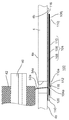
図3は、実施の形態に係るディスク駆動装置100の部分的な拡大断面図である。
ベース4の下面4bにはストリップ状のベースフィルム108とストリップ状のカバーフィルム110との間に駆動配線となるストリップ状の配線導体106が積層された配線部材104が固着される。配線部材104はベースフィルム108とベース4との間に接着部材を介して貼り付けられている。この接着部材として両面テープ116を用いると、硬化時間を殆ど必要としないため作業効率が良好である。ベースフィルム108とカバーフィルム110とは例えば厚さが12〜50μmのポリイミド(polyimide)やポリエステル(Polyester)のフィルムから公知の方法により所定の形状に形成できる。配線導体106は例えば厚さが12〜50μmの銅箔から公知の方法により所定の形状に形成できる。配線部材104はベース孔54aを覆うようにベース4の下面4bに貼り付けられる。
FIG. 3 is a partially enlarged sectional view of the
On the
配線部材104は平面方向で一方の端側にワイヤ接続部112を有し、他方の端側に別の接続部106jを有する。別の接続部106jには駆動回路(不図示)につながる配線ワイヤ(不図示)が電気的に接続される。ワイヤ接続部112と別の接続部106jとの間は配線導体106が連続しているから、駆動回路は配線導体106を通じてコイル42に駆動電流を供給できる。配線部材104は、カバーフィルム110の開口110a、110jがワイヤ接続部112と別の接続部106jに対応する位置にそれぞれ形成される。配線導体106はカバーフィルム110の開口110a、110jに対応する領域において導体が露出している。配線部材104は、その平面方向にそれぞれのベース孔54aの少なくとも一部と重複する位置に配線部材104を貫通するフィルム孔104aを含む。リードワイヤ52aはベース孔54aとフィルム孔104aとを通りカバーフィルム110の下面側に延在する。リードワイヤ52aの先端は別の接続部106jに向かってほぼ直角に折り曲げられる。リードワイヤ52aの先端はワイヤ接続部112に例えばはんだ118を用いた半田付けによって固定され電気的に接続される。
The
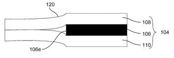
ここで本発明者は、ベース孔にリークを生じる原因を検討し、以下のような知見を得た。図6は配線部材104の断面を示す模式図である。なお、図6および以下の図7、図8は理解を容易にするため特徴部分を強調して描いている。図6で示すように、配線部材104には、ベースフィルム108とカバーフィルム110との間に、配線導体106が介在する介在領域と、配線導体106が介在しない非介在領域が存在する。非介在領域の介在領域から離れた部分の配線部材104の厚みは、介在領域より配線導体106の厚さ分だけ薄い。また非介在領域は、配線導体106の外縁106eの平面方向で外側周囲に導体の厚さ分だけ厚さが漸減する領域である厚さ減少部120が形成される。図7は配線部材104をベース4の下面4bに貼り付けた状態の断面を示す模式図である。配線部材104をベース4の下面4bに貼り付けると厚さ減少部120とベースの間には隙間120aが形成される。隙間120aとベース孔54aとが平面方向で重複すると、矢印140に示すようにベース孔54aと隙間120aは連通する。図8は配線部材をベース4の下面に貼り付けた状態における平面方向通路Pを示す下面模式図である。なお理解を容易にするため図8はカバーフィルム110は図示しない。また、ベース4はベース孔54aのみを記載している。配線導体106(ハッチング部)の縁に沿って隙間120aが平面方向の通路P(ハッチング部と破線の間)を形成している。通路Pは配線導体106の縁に沿って配線部材104の外縁104eまで連続的に形成される。このため通路Pとベース孔54aとが一部でもつながると、ベース孔54aにパーティクルのリーク路が形成されうる。つまり、配線部材104の外縁まで連続する厚さ減少部120がベース孔54aと平面方向で重複することがベース孔54aの気密が低下する原因となることが判明した。
Here, the present inventor examined the cause of leakage in the base hole and obtained the following knowledge. FIG. 6 is a schematic view showing a cross section of the
本実施の形態において、配線部材104はベースフィルム108とカバーフィルム110の厚さがそれぞれ25μmで、配線導体106の厚さが35μmに形成される。この結果、配線部材104の厚さは、配線導体106が介在する介在領域では85μmで、配線導体106が介在しない非介在領域の厚さ減少部120以外の領域は50μmである。つまり配線導体106の縁に沿って形成される厚さ減少部120には片面で約17μmの段差が生じる。このような配線部材104をベース4の下面4bに貼り付けると厚さ減少部120に沿った平面方向の通路Pが形成される。
In the present embodiment, the
上記の知見に対応して本実施の形態においては、厚さ減少部120は平面方向において前記ベース孔の外側に位置するように設けられる。このためベース孔54aが通路Pと連通して気密が低下する可能性を低減できる。
Corresponding to the above findings, in the present embodiment, the
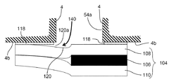
図4は図2のディスク駆動装置の配線部材104を中心とする部分的な下面図である。図4は理解を容易にするためカバーフィルム110を除いた状態とカバーフィルム110とに分離し、またはんだ118のない状態を示している。図5は、図4の配線部材104の別の一例の平面図である。図5は理解を容易にするためカバーフィルム110を除いた状態を示している。外形線はベースフィルム108の外形線を示す。ハッチングした領域は導体が存在する領域である配線導体106を示す。
FIG. 4 is a partial bottom view centering on the
まず図4に沿って説明する。配線導体106はベースフィルム108とカバーフィルム110より熱伝導率が高いので、熱は配線導体106に沿って伝わる。このため、ワイヤ接続部112の周辺の配線導体106の面積が広くなると、その面積に応じてワイヤ接続部112の熱容量が大きくなる。ワイヤ接続部112の熱容量が大きくなると、はんだゴテを接触させた際にはんだが溶ける温度に達するまでの時間が長くなる。この結果、リードワイヤ52aをワイヤ接続部112に半田付けに要する時間が長くなり作業効率が低下する。ヒータの発熱量が大きなはんだゴテを使用する方法も考えられるが、そのようなはんだゴテを用いると、その熱によりリードワイヤ52aや配線導体106を劣化させるおそれがある。この課題に対応して、本実施の形態においてはベースフィルム108とカバーフィルム110の間であって平面方向においてワイヤ接続部112と厚さ減少部120との間に導体が無い領域であるスロット114が配線部材104の外側の領域と分離して設けられる。スロット114は導体が介在していないから、スロット114の両側で熱の伝導を阻害する。スロット114はワイヤ接続部112の熱が周辺の配線導体106に伝達されること阻害する。この結果、はんだゴテをワイヤ接続部112に接触させた際にはんだが溶ける温度に達するまでの時間が短くなる。
First, a description will be given with reference to FIG. Since the
配線部材104は、スロット114に対応する部分がベースフィルム108とカバーフィルム110だけとなるので、厚み方向に凹部(不図示)を形成することがある。このような凹部が配線部材104の外側の空間と連通すると、パーティクルのリーク路が形成される懸念がある。この懸念に対応して本実施の形態においては、スロット114は配線導体106に囲まれて配線部材104の外側の領域と分離して設けられる。スロット114と配線部材104の外縁との間には配線導体106が介在するから、スロット114に対応する厚み方向の凹部が配線部材104の外側の空間と連通する可能性は大幅に低くなる。
Since the
ワイヤ接続部112の面積が狭いとリードワイヤ52aをワイヤ接続部112に半田付け作業の作業効率が低下する。この課題に対応してスロット114は、平面方向において厚さ減少部120とベース孔54a(図4において破線で示される。)との間に設けてもよい。ベース孔54aが小さい場合でもワイヤ接続部112の面積を広くできるから作業性の低下を抑えられる。図4の本実施の形態においては、スロット114は平面方向において一部がベース孔54aの縁と重複して設けている。
If the area of the
スロット114は一のワイヤ接続部112に対して複数設けてもよい。図4の本実施の形態において、スロット114は一のワイヤ接続部112に対して4つ設けている。また、スロット114は平面方向においてワイヤ接続部112を挟むように設けている。スロット114をワイヤ接続部112の一方の側にのみ設ける場合に比べて熱伝導を阻害する効果が一層高くなる。また本実施の形態において、スロット114は略弧状に形成される。直線である場合に比べてスロット114の長さを長くして熱伝導の阻害効果を高めうる。また、図4に示すように、スロット114は平面方向において1つのワイヤ接続部112を複数に分けた複数のスロット114で囲むように設けてもよい。スロット114と隣のスロット114との間に存在する導体によってワイヤ接続部112がスロット112の外側周囲の配線導体106とつながる。このためワイヤ接続部112がベースフィルム108から剥がれ難くなる点で好ましい。また図5に示すように、スロット114は平面方向において1つのワイヤ接続部112を1つのスロット114で囲むように設けてもよい。熱伝導を阻害する効果が一層向上する。
A plurality of
図4及び図5の本実施の形態においてカバーフィルム110の開口110aはスロット114と平面方向で一部が重複している。スロット114の内部の空気が密封されて外部空間と気圧差で膨張や収縮をすることが抑えられる。また図6の本実施の形態においてスロット114の少なくとも一部は、平面方向においてベース孔54aと重複している。ベース孔54aが大きい場合でもワイヤ接続部112の面積を抑えることが可能となる点で有利である。
4 and 5, the
スロット114の平面方向の幅寸法が狭すぎると、熱伝導を阻害する効果が低下して作業性が悪化する懸念がある。また、スロット114の平面方向の幅寸法が広すぎるとスロット114に対応する部分における凹部の深さ寸法が深くなり、平面方向のリーク路が形成される懸念がある。本実施の形態においては、配線導体106の厚み寸法は0.01〜0.05mmの範囲で、スロット114の平面方向の最小幅寸法は0.3〜0.7mmの範囲内である。この構成で作業性は実用上で問題なく、また十分なリーク抑制効果が得られることが確認されている。
If the width dimension of the
またリードワイヤ52b及び52cについての構成は上記リードワイヤ52aについての構成と同様であり、重複する説明は省略する。以上の構成によりベース孔からリークする可能性が軽減され気密の信頼性が向上する。その結果、ベース4の上面4a側をパーティクルの少ない清浄な状態に保つことができる。
The configuration of the
以上、実施の形態にもとづき本発明を説明したが、これらの実施の形態は例示であり、本発明の原理、応用を示しているにすぎないことはいうまでもなく、実施の形態には、請求の範囲に規定された本発明の思想を逸脱しない範囲において、多くの変形例や配置の変更が可能なこと、またそうした変形例も本発明の範囲にあることは当業者に理解されるところである。 The present invention has been described above based on the embodiments. However, these embodiments are merely examples, and it is needless to say that they merely illustrate the principle and application of the present invention. It is understood by those skilled in the art that many modifications and arrangements can be made without departing from the spirit of the present invention defined in the claims, and that such modifications are also within the scope of the present invention. is there.
本実施の形態においては、平面方向においてベース孔と重複する位置に配線部材の貫通孔を設ける例について説明したがこれに限られない。配線部材を貫通する孔はベース孔と重複を避けた位置に設ける構成であっても同様の効果を奏する。本実施の形態においては、またワイヤ接続部が配線部材の貫通孔の周辺に設けられる例について説明したがこれに限られない。ワイヤ接続部は貫通孔を避けて設ける構成であっても同様の効果を奏する。 In the present embodiment, the example in which the through hole of the wiring member is provided at a position overlapping the base hole in the planar direction has been described, but the present invention is not limited to this. Even if the hole penetrating the wiring member is provided at a position avoiding overlapping with the base hole, the same effect can be obtained. In the present embodiment, the example in which the wire connecting portion is provided around the through hole of the wiring member has been described, but the present invention is not limited thereto. Even if the wire connecting portion is configured to avoid the through hole, the same effect can be obtained.
本実施の形態においては、一般的な仕様のベースフィルム、カバーフィルム及び配線導体により構成される例について説明したがこれに限られない。別の仕様のベースフィルム、カバーフィルム及び配線導体により構成しても同様の効果を奏する。 In the present embodiment, an example of a base film having a general specification, a cover film, and a wiring conductor has been described, but is not limited thereto. Even if it is constituted by a base film, a cover film, and a wiring conductor having different specifications, the same effect can be obtained.
本実施の形態においては、ブラシレスモータの3本のリード線をそれぞれ1箇所のベース孔に1本のワイヤを通す例について説明したがこれに限られない。1箇所のベース孔に複数本のワイヤを通すように構成しても同様の効果を奏する。また、ブラシレスモータのリード線の数は3本に限られないことは当業者に理解されるところである。 In the present embodiment, the example in which one wire is passed through each of the three lead wires of the brushless motor through one base hole is not limited thereto. The same effect can be obtained even when a plurality of wires are passed through one base hole. Further, those skilled in the art understand that the number of lead wires of the brushless motor is not limited to three.
本実施の形態においては、ベース孔に接着剤を充填しない例について説明したがこれに限られない。例えばベース孔に接着剤を充填するようにしてもよい。また、ワイヤ接続部に接続したリードワイヤを覆うように接着剤を塗布してもよい。また、本実施の形態においては、配線部材は両面テープによって固着する例について説明したがこれに限られない。例えば接着剤を用いて固着する方法や複数の固着方向を併用して固着してもよい。また、ベースの下面に配線部材を収容可能な凹みを設け、配線部材を当該凹みに固着し、配線部材の縁と当該凹みとに亘ってシール材が固着されてもよい。ベース孔のリークを一層低減できる。 In the present embodiment, the example in which the base hole is not filled with the adhesive has been described, but the present invention is not limited to this. For example, the base hole may be filled with an adhesive. Moreover, you may apply | coat an adhesive agent so that the lead wire connected to the wire connection part may be covered. In the present embodiment, the example in which the wiring member is fixed by the double-sided tape has been described, but the present invention is not limited to this. For example, it may be fixed using a method of fixing using an adhesive or a plurality of fixing directions. Further, a recess that can accommodate the wiring member is provided on the lower surface of the base, the wiring member is fixed to the recess, and the sealing material is fixed to the edge of the wiring member and the recess. Base hole leakage can be further reduced.
本実施の形態においては、モータのリードワイヤの例について説明したがこれに限られない。例えばボイスコイルモータのリードワイヤであってもよい。同様の効果を奏する。本実施の形態においては、モータのリードワイヤをワイヤ接続部に半田づけする例について説明したがこれに限られない。例えばモータのリードワイヤをワイヤ接続部にその他のロウ付け方法や溶接方法によって接続してもよい。 In the present embodiment, an example of a motor lead wire has been described, but the present invention is not limited to this. For example, it may be a lead wire of a voice coil motor. The same effect is produced. In the present embodiment, the example in which the lead wire of the motor is soldered to the wire connection portion has been described, but the present invention is not limited to this. For example, the lead wire of the motor may be connected to the wire connection portion by other brazing methods or welding methods.
本実施の形態ではスリーブがベースに固定され、シャフトがスリーブに対して回転する場合について説明したが、たとえばシャフトがベースに固定され、スリーブがハブと共にシャフトに対して回転するようなシャフト固定型であってもよい。 In the present embodiment, the case where the sleeve is fixed to the base and the shaft rotates with respect to the sleeve has been described. However, for example, the shaft is fixed to the shaft so that the shaft is fixed to the base and the sleeve rotates together with the hub. There may be.
100 回転機器、4 ベース、6 回転体、8 記録ディスク、10 データリード/ライト部、12 軸受ユニット、14 スイングアーム、16 ボイスコイルモータ、18、20 ブラシレスモータ、 ピボットアセンブリ、26 シャフト、28 ハブ、30 フランジ、32 円筒状マグネット、36 クランパ、38 スクリュウ、40 コア、42 コイル、44 ハウジング、46 スリーブ、48 潤滑剤、52 リードワイヤ、54 ベース孔、104 配線部材、104a フィルム孔、106 配線導体、108 第1フィルム、110 第2フィルム、112 ワイヤ接続部、114 スロット、116 両面テープ、118 はんだ、120 厚さ減少部。 100 rotating device, 4 base, 6 rotating body, 8 recording disk, 10 data read / write unit, 12 bearing unit, 14 swing arm, 16 voice coil motor, 18, 20 brushless motor, pivot assembly, 26 shaft, 28 hub, 30 flange, 32 cylindrical magnet, 36 clamper, 38 screw, 40 core, 42 coil, 44 housing, 46 sleeve, 48 lubricant, 52 lead wire, 54 base hole, 104 wiring member, 104a film hole, 106 wiring conductor, 108 First film, 110 Second film, 112 Wire connection part, 114 slot, 116 Double-sided tape, 118 Solder, 120 Thickness reduction part.
Claims (9)
前記ベースの前記第1面側に設けられ記録ディスクを載置すべき回転体と、
第1フィルムと第2フィルムと前記第1フィルムと前記第2フィルムの間に間在する配線導体とを含み、前記ベースの第2面に設けられ前記ベース孔を覆う配線部材と、
前記ベース孔を通り、前記配線導体のワイヤ接続部に固定されるリードワイヤと、
前記配線部材に含まれ、前記配線導体の縁に対応して厚さが減少する部分であって、平面方向において前記ベース孔の外側に位置する厚さ減少部と、
前記配線部材に含まれ、前記第1フィルムと前記第2フィルムの間で平面方向において前記配線導体によって全周を囲まれた導体が無い領域であって、前記ワイヤ接続部と前記厚さ減少部との間に介在するスロットと、
を備えるディスク駆動装置。 A base having a base hole penetrating the first surface and the second surface opposite to the first surface;
A rotating body provided on the first surface side of the base and on which a recording disk is to be placed;
A wiring member that includes a first film, a second film, a wiring conductor interposed between the first film and the second film, and is provided on a second surface of the base and covers the base hole;
A lead wire that passes through the base hole and is fixed to the wire connection portion of the wiring conductor;
A thickness reducing portion that is included in the wiring member and has a thickness that decreases in correspondence with an edge of the wiring conductor, and is located outside the base hole in a planar direction;
A region that is included in the wiring member and has no conductor surrounded by the wiring conductor in the planar direction between the first film and the second film, the wire connecting portion and the thickness reducing portion A slot interposed between and
A disk drive device comprising:
前記リードワイヤは前記ベース孔と前記フィルム孔とを通り、半田付けによって前記ワイヤ接続部に固定されることを特徴とする請求項1から6のいずれかに記載のディスク駆動装置。 The wiring member further includes a film hole penetrating the wiring member at a position overlapping the base hole in a planar direction,
7. The disk drive device according to claim 1, wherein the lead wire passes through the base hole and the film hole and is fixed to the wire connecting portion by soldering.
Priority Applications (2)
| Application Number | Priority Date | Filing Date | Title |
|---|---|---|---|
| JP2011276688A JP2013127830A (en) | 2011-12-19 | 2011-12-19 | Disk drive device |
| US13/674,273 US20130154409A1 (en) | 2011-12-19 | 2012-11-12 | Disk drive device |
Applications Claiming Priority (1)
| Application Number | Priority Date | Filing Date | Title |
|---|---|---|---|
| JP2011276688A JP2013127830A (en) | 2011-12-19 | 2011-12-19 | Disk drive device |
Publications (2)
| Publication Number | Publication Date |
|---|---|
| JP2013127830A true JP2013127830A (en) | 2013-06-27 |
| JP2013127830A5 JP2013127830A5 (en) | 2014-12-04 |
Family
ID=48609413
Family Applications (1)
| Application Number | Title | Priority Date | Filing Date |
|---|---|---|---|
| JP2011276688A Pending JP2013127830A (en) | 2011-12-19 | 2011-12-19 | Disk drive device |
Country Status (2)
| Country | Link |
|---|---|
| US (1) | US20130154409A1 (en) |
| JP (1) | JP2013127830A (en) |
Families Citing this family (2)
| Publication number | Priority date | Publication date | Assignee | Title |
|---|---|---|---|---|
| CN113314158B (en) | 2020-02-27 | 2023-01-06 | 株式会社东芝 | Disk device |
| JP2023013465A (en) * | 2021-07-16 | 2023-01-26 | 日本電産株式会社 | Motor and disc driving device |
Citations (3)
| Publication number | Priority date | Publication date | Assignee | Title |
|---|---|---|---|---|
| JPH0527897U (en) * | 1991-09-19 | 1993-04-09 | セイコーエプソン株式会社 | Magnetic recording device |
| JP2006185553A (en) * | 2004-12-28 | 2006-07-13 | Nippon Densan Corp | Motor unit, recording disk driving unit, and sealing method of through-hole formed on housing member |
| JP2010153097A (en) * | 2008-12-24 | 2010-07-08 | Teikoku Tsushin Kogyo Co Ltd | Terminal plate connecting structure and connecting method to circuit board |
Family Cites Families (8)
| Publication number | Priority date | Publication date | Assignee | Title |
|---|---|---|---|---|
| JPH0624365U (en) * | 1991-11-29 | 1994-03-29 | 株式会社三協精機製作所 | Brushless motor |
| JP2008220068A (en) * | 2007-03-06 | 2008-09-18 | Matsushita Electric Ind Co Ltd | Motor |
| US8324771B2 (en) * | 2008-02-06 | 2012-12-04 | Nidec Corporation | Spindle motor and storage disk drive apparatus |
| JP2010218612A (en) * | 2009-03-16 | 2010-09-30 | Alphana Technology Co Ltd | Disk drive device |
| KR101130628B1 (en) * | 2010-04-07 | 2012-04-02 | 니혼 덴산 가부시키가이샤 | Spindle motor and storage disk drive having the same |
| JP2012165543A (en) * | 2011-02-07 | 2012-08-30 | Nippon Densan Corp | Spindle motor, disk drive, and method of manufacturing spindle motor |
| JP5903793B2 (en) * | 2011-08-03 | 2016-04-13 | 日本電産株式会社 | Spindle motor manufacturing method, spindle motor, and disk drive device |
| US8665557B1 (en) * | 2013-03-13 | 2014-03-04 | Nidec Corporation | Spindle motor and disk drive apparatus |
-
2011
- 2011-12-19 JP JP2011276688A patent/JP2013127830A/en active Pending
-
2012
- 2012-11-12 US US13/674,273 patent/US20130154409A1/en not_active Abandoned
Patent Citations (3)
| Publication number | Priority date | Publication date | Assignee | Title |
|---|---|---|---|---|
| JPH0527897U (en) * | 1991-09-19 | 1993-04-09 | セイコーエプソン株式会社 | Magnetic recording device |
| JP2006185553A (en) * | 2004-12-28 | 2006-07-13 | Nippon Densan Corp | Motor unit, recording disk driving unit, and sealing method of through-hole formed on housing member |
| JP2010153097A (en) * | 2008-12-24 | 2010-07-08 | Teikoku Tsushin Kogyo Co Ltd | Terminal plate connecting structure and connecting method to circuit board |
Also Published As
| Publication number | Publication date |
|---|---|
| US20130154409A1 (en) | 2013-06-20 |
Similar Documents
| Publication | Publication Date | Title |
|---|---|---|
| US8674570B2 (en) | Disk drive device for rotating a disk | |
| US8164851B2 (en) | Base unit for use in storage disk drive apparatus, spindle motor including the base unit, and storage disk drive apparatus including the spindle motor | |
| US8416524B2 (en) | Spindle motor having connecting mechanism connecting lead wire and circuit board, and storage disk drive having the same | |
| JP5685707B2 (en) | Spindle motor and hard disk drive equipped with the spindle motor | |
| US20120182645A1 (en) | Rotating machine comprising insulation sheet for insulating coil and base, and method of producing the rotating machine | |
| US8451558B2 (en) | Disk drive device with appropriate number of combinations of magnetic poles and salient poles to reduce thickness of the disk drive device | |
| JP5591297B2 (en) | Hard disk drive | |
| JP2014036447A (en) | Spindle motor, and disk drive | |
| JP2012005255A (en) | Rotary apparatus and method for manufacturing the same | |
| US8665557B1 (en) | Spindle motor and disk drive apparatus | |
| JP2006223062A (en) | Motor and recording disc drive device | |
| JP2013127830A (en) | Disk drive device | |
| JP2013078249A (en) | Rotary apparatus | |
| US8922944B2 (en) | Rotating device | |
| US8908323B2 (en) | Rotating device | |
| JP2016208676A (en) | Rotary apparatus and production method of rotary apparatus | |
| US20140334036A1 (en) | Rotating device | |
| US20140139949A1 (en) | Rotating device | |
| JP2016158439A (en) | Motor and disk drive device | |
| JP2009268166A (en) | Spindle motor and disk drive device | |
| JP2015152080A (en) | Rotary equipment | |
| JP2019061730A (en) | Base unit and disk drive device | |
| US20090168639A1 (en) | Spindle motor and disk drive apparatus provided with the same | |
| JP2012157164A (en) | Rotary apparatus and manufacturing method of the same | |
| US20150340058A1 (en) | Rotating device |
Legal Events
| Date | Code | Title | Description |
|---|---|---|---|
| A521 | Written amendment |
Free format text: JAPANESE INTERMEDIATE CODE: A523 Effective date: 20141017 |
|
| A621 | Written request for application examination |
Free format text: JAPANESE INTERMEDIATE CODE: A621 Effective date: 20141210 |
|
| RD03 | Notification of appointment of power of attorney |
Free format text: JAPANESE INTERMEDIATE CODE: A7423 Effective date: 20150327 |
|
| A977 | Report on retrieval |
Free format text: JAPANESE INTERMEDIATE CODE: A971007 Effective date: 20150727 |
|
| A131 | Notification of reasons for refusal |
Free format text: JAPANESE INTERMEDIATE CODE: A131 Effective date: 20150818 |
|
| A02 | Decision of refusal |
Free format text: JAPANESE INTERMEDIATE CODE: A02 Effective date: 20160105 |