JP2013117231A - Combustor and gas turbine with the same - Google Patents
Combustor and gas turbine with the same Download PDFInfo
- Publication number
- JP2013117231A JP2013117231A JP2013039522A JP2013039522A JP2013117231A JP 2013117231 A JP2013117231 A JP 2013117231A JP 2013039522 A JP2013039522 A JP 2013039522A JP 2013039522 A JP2013039522 A JP 2013039522A JP 2013117231 A JP2013117231 A JP 2013117231A
- Authority
- JP
- Japan
- Prior art keywords
- acoustic
- damper
- combustor
- cover
- resonance space
- Prior art date
- Legal status (The legal status is an assumption and is not a legal conclusion. Google has not performed a legal analysis and makes no representation as to the accuracy of the status listed.)
- Granted
Links
Images


Classifications
-
- F—MECHANICAL ENGINEERING; LIGHTING; HEATING; WEAPONS; BLASTING
- F23—COMBUSTION APPARATUS; COMBUSTION PROCESSES
- F23R—GENERATING COMBUSTION PRODUCTS OF HIGH PRESSURE OR HIGH VELOCITY, e.g. GAS-TURBINE COMBUSTION CHAMBERS
- F23R3/00—Continuous combustion chambers using liquid or gaseous fuel
- F23R3/02—Continuous combustion chambers using liquid or gaseous fuel characterised by the air-flow or gas-flow configuration
- F23R3/16—Continuous combustion chambers using liquid or gaseous fuel characterised by the air-flow or gas-flow configuration with devices inside the flame tube or the combustion chamber to influence the air or gas flow
-
- F—MECHANICAL ENGINEERING; LIGHTING; HEATING; WEAPONS; BLASTING
- F23—COMBUSTION APPARATUS; COMBUSTION PROCESSES
- F23R—GENERATING COMBUSTION PRODUCTS OF HIGH PRESSURE OR HIGH VELOCITY, e.g. GAS-TURBINE COMBUSTION CHAMBERS
- F23R3/00—Continuous combustion chambers using liquid or gaseous fuel
- F23R3/005—Combined with pressure or heat exchangers
-
- F—MECHANICAL ENGINEERING; LIGHTING; HEATING; WEAPONS; BLASTING
- F01—MACHINES OR ENGINES IN GENERAL; ENGINE PLANTS IN GENERAL; STEAM ENGINES
- F01D—NON-POSITIVE DISPLACEMENT MACHINES OR ENGINES, e.g. STEAM TURBINES
- F01D25/00—Component parts, details, or accessories, not provided for in, or of interest apart from, other groups
- F01D25/04—Antivibration arrangements
-
- F—MECHANICAL ENGINEERING; LIGHTING; HEATING; WEAPONS; BLASTING
- F01—MACHINES OR ENGINES IN GENERAL; ENGINE PLANTS IN GENERAL; STEAM ENGINES
- F01D—NON-POSITIVE DISPLACEMENT MACHINES OR ENGINES, e.g. STEAM TURBINES
- F01D9/00—Stators
- F01D9/02—Nozzles; Nozzle boxes; Stator blades; Guide conduits, e.g. individual nozzles
- F01D9/023—Transition ducts between combustor cans and first stage of the turbine in gas-turbine engines; their cooling or sealings
-
- F—MECHANICAL ENGINEERING; LIGHTING; HEATING; WEAPONS; BLASTING
- F23—COMBUSTION APPARATUS; COMBUSTION PROCESSES
- F23M—CASINGS, LININGS, WALLS OR DOORS SPECIALLY ADAPTED FOR COMBUSTION CHAMBERS, e.g. FIREBRIDGES; DEVICES FOR DEFLECTING AIR, FLAMES OR COMBUSTION PRODUCTS IN COMBUSTION CHAMBERS; SAFETY ARRANGEMENTS SPECIALLY ADAPTED FOR COMBUSTION APPARATUS; DETAILS OF COMBUSTION CHAMBERS, NOT OTHERWISE PROVIDED FOR
- F23M20/00—Details of combustion chambers, not otherwise provided for, e.g. means for storing heat from flames
- F23M20/005—Noise absorbing means
-
- F—MECHANICAL ENGINEERING; LIGHTING; HEATING; WEAPONS; BLASTING
- F23—COMBUSTION APPARATUS; COMBUSTION PROCESSES
- F23R—GENERATING COMBUSTION PRODUCTS OF HIGH PRESSURE OR HIGH VELOCITY, e.g. GAS-TURBINE COMBUSTION CHAMBERS
- F23R3/00—Continuous combustion chambers using liquid or gaseous fuel
- F23R3/02—Continuous combustion chambers using liquid or gaseous fuel characterised by the air-flow or gas-flow configuration
- F23R3/04—Air inlet arrangements
- F23R3/06—Arrangement of apertures along the flame tube
-
- F—MECHANICAL ENGINEERING; LIGHTING; HEATING; WEAPONS; BLASTING
- F23—COMBUSTION APPARATUS; COMBUSTION PROCESSES
- F23R—GENERATING COMBUSTION PRODUCTS OF HIGH PRESSURE OR HIGH VELOCITY, e.g. GAS-TURBINE COMBUSTION CHAMBERS
- F23R3/00—Continuous combustion chambers using liquid or gaseous fuel
- F23R3/42—Continuous combustion chambers using liquid or gaseous fuel characterised by the arrangement or form of the flame tubes or combustion chambers
- F23R3/46—Combustion chambers comprising an annular arrangement of several essentially tubular flame tubes within a common annular casing or within individual casings
-
- F—MECHANICAL ENGINEERING; LIGHTING; HEATING; WEAPONS; BLASTING
- F23—COMBUSTION APPARATUS; COMBUSTION PROCESSES
- F23R—GENERATING COMBUSTION PRODUCTS OF HIGH PRESSURE OR HIGH VELOCITY, e.g. GAS-TURBINE COMBUSTION CHAMBERS
- F23R2900/00—Special features of, or arrangements for continuous combustion chambers; Combustion processes therefor
- F23R2900/00014—Reducing thermo-acoustic vibrations by passive means, e.g. by Helmholtz resonators
Landscapes
- Engineering & Computer Science (AREA)
- Mechanical Engineering (AREA)
- General Engineering & Computer Science (AREA)
- Chemical & Material Sciences (AREA)
- Combustion & Propulsion (AREA)
- Soundproofing, Sound Blocking, And Sound Damping (AREA)
- Structures Of Non-Positive Displacement Pumps (AREA)
- Exhaust Silencers (AREA)
Abstract
Description
本発明は、燃焼器およびこれを備えたガスタービンに関する。 The present invention relates to a combustor and a gas turbine including the combustor.
ガスタービンは、圧縮機と、燃焼器と、タービンとを有しており、圧縮機では空気を取り込んで圧縮して高圧にし、高圧になった空気を燃焼器に送り込む。
燃焼器では、高圧の空気に対して燃料を吹き出して燃料を燃焼させる。燃料が燃焼することにより発生する高温の燃焼ガスは、タービンに送られ、この高温の燃焼ガスがタービンを駆動する。
このタービンと前記圧縮機とは同じ回転軸の回りに回転するため、タービンがこのように駆動することにより、圧縮機も駆動し、上述したように空気を取り入れて圧縮をする。
The gas turbine has a compressor, a combustor, and a turbine. The compressor takes in air, compresses it to a high pressure, and sends the high-pressure air to the combustor.
In the combustor, the fuel is blown out to the high pressure air to burn the fuel. The high-temperature combustion gas generated by the combustion of the fuel is sent to the turbine, and this high-temperature combustion gas drives the turbine.
Since the turbine and the compressor rotate around the same rotation axis, the turbine is driven in this manner, so that the compressor is also driven, and the air is taken in and compressed as described above.
このように作動するガスタービンは、燃料が燃焼する際に燃焼振動が発生する場合があり、この燃焼振動は、ガスタービン運転時の騒音や振動の原因となっていた。
特に、近年のガスタービンでは、運転時の環境への影響を考慮して排出ガスの低NOx(窒素酸化物)化が図られているが、低NOx化を図るためには燃料の希薄燃焼が多用される。
しかし、希薄燃焼は燃焼が不安定になり易く、このため燃焼振動が発生し易くなっていた。そこで、この燃焼振動に起因する音や振動を抑制するために、燃焼器に、たとえば、多孔板とその外側を覆うカバーとによって構成される比較的高周波の音を吸音する音響ライナを設けたり、大きな共鳴空間を有する比較的低周波の音を吸音する音響ダンパを設けたりしていた。
The gas turbine that operates in this manner may generate combustion vibration when the fuel burns, and this combustion vibration causes noise and vibration during the operation of the gas turbine.
In particular, in recent gas turbines, the NOx (nitrogen oxide) of exhaust gas is reduced in consideration of the influence on the environment during operation. However, in order to reduce NOx, lean combustion of fuel is required. Often used.
However, lean combustion tends to cause instability of combustion, and combustion vibration is likely to occur. Therefore, in order to suppress the noise and vibration caused by this combustion vibration, for example, an acoustic liner that absorbs relatively high-frequency sound constituted by a perforated plate and a cover that covers the outside of the combustor is provided. An acoustic damper that absorbs relatively low-frequency sound having a large resonance space has been provided.
比較的高周波の音を対象とする音響ライナでは、共鳴空間の容積が小さいので、その設置にあたり車室内のスペース上の制約は少なかった。
一方、比較的高周波の音を対象とする音響ダンパは、共鳴空間の容積が大きいので、その設置にあたり車室内のスペース上の制約を受けていた。
従来、燃焼ガスに車室内の空気を導入するバイパス流路を備えている燃焼器では、音響ダンパは、たとえば、特許文献1に示されるように、バイパス流路の周囲を用いて設置されている。
また、バイパス流路を備えていない形式の燃焼器では、たとえば、特許文献2に示されるように、燃焼器に環装する音響ライナに音響ダンパを接続し、音響ダンパの共鳴空間を形成する音響部を燃焼器の軸線方向あるいは半径方向へ延在するように設置するものが提案されている。
In acoustic liners that target relatively high-frequency sounds, the volume of the resonance space is small, so there are few restrictions on the space in the vehicle interior.
On the other hand, acoustic dampers for relatively high-frequency sounds have a large volume of resonance space, and thus are limited in space in the vehicle interior.
Conventionally, in a combustor provided with a bypass flow path for introducing air in a vehicle interior to combustion gas, the acoustic damper is installed using the periphery of the bypass flow path as shown in
Further, in a combustor of a type that does not include a bypass flow path, for example, as shown in Patent Document 2, an acoustic damper is connected to an acoustic liner that is attached to the combustor to form a resonance space of the acoustic damper. It has been proposed to install the portion so as to extend in the axial direction or radial direction of the combustor.
ところで、特許文献1に示されるものは、バイパス流路および音響ダンパを設置するために燃焼器の外側に大きな空間が必要である。また、特許文献2に示されるものでは、音響ダンパは、半径方向に延在するものでは当然ながら、軸線方向に延在するものでも共鳴空間の容積(全長)を確保するために半径方向に折り曲げられているので、バイパス流路および音響ダンパを設置するために燃焼器の外側に大きな空間が必要である。
このように、大きな車室空間が必要となるので、ハウジングが大型化し、たとえば、ガスタービンの陸上輸送が不可能となる恐れがある。この輸送コストを含め、製造コストが大きくなる。
燃焼器は定期的にメンテナンスされるが、特許文献1では、バイパス流路を取り外さないと、また、特許文献2では、音響ダンパを取り外さないと、燃焼器は引き抜けないので、このメンテナンス作業が大掛かりとなる。
By the way, what is shown by
As described above, since a large vehicle compartment space is required, the housing becomes large, and there is a possibility that, for example, land transportation of the gas turbine may be impossible. Including this transportation cost, the manufacturing cost increases.
Although the combustor is regularly maintained, in
本発明は、上記課題に鑑み、音響ダンパの取付空間を小さくし、小型化でき、かつ、メンテナンス性を向上し得る燃焼器およびこれを用いたガスタービンを提供することを目的とする。 In view of the above problems, an object of the present invention is to provide a combustor that can reduce the mounting space of an acoustic damper, reduce the size, and improve maintainability, and a gas turbine using the combustor.
上記目的を達成するために、本発明は、以下の手段を提供する。
本発明の第1態様は、内部に燃焼領域を形成する筒体と、該燃焼領域に連通する音響ダンパ共鳴空間を有する音響部を有する音響ダンパと、を備える燃焼器であって、前記音響部は、前記筒体に沿って、前記筒体の軸線方向に対して交差する方向に延在するように設置されており、前記筒体を構成し、厚さ方向に貫通する複数の貫通孔が設けられている多孔板部と該多孔板部の周囲に間隔を空けて覆うように設けられたカバー部材とによって形成される空間を、仕切り部材によって前記筒体の周方向に複数の空間に分割し、分割された前記複数の空間のうちの少なくとも一つが、前記音響ダンパ共鳴空間の一部となり、分割された前記複数の空間のうちの他の少なくとも一つが、音響ライナ共鳴空間となっている燃焼器である。
In order to achieve the above object, the present invention provides the following means.
1st aspect of this invention is a combustor provided with the cylinder which forms a combustion area inside, and an acoustic damper which has an acoustic part which has an acoustic damper resonance space connected to this combustion area, The acoustic part Is installed so as to extend along the cylindrical body in a direction intersecting the axial direction of the cylindrical body, and a plurality of through-holes constituting the cylindrical body and penetrating in the thickness direction are provided. A space formed by the perforated plate portion provided and a cover member provided so as to cover the perimeter of the perforated plate portion with an interval is divided into a plurality of spaces in the circumferential direction of the cylindrical body by a partition member Then, at least one of the divided spaces becomes a part of the acoustic damper resonance space, and at least one of the divided spaces becomes an acoustic liner resonance space. It is a combustor.
本態様によれば、音響ダンパ共鳴空間を有する音響部は、筒体に沿って、筒体の軸線方向に対して交差する方向、言い換えると、周方向に延在するように設置されているので、音響部は筒体の周方向の一定箇所に集中することなく、周方向に広く配置されることになる。これにより、音響部は筒体の外周側への突起が抑制されるので、燃焼器の外側に必要な空間を削減することができる。
したがって、車室を小さくできるので、それを形成するハウジングを小型化することができる。このため、たとえば、ガスタービンの陸上輸送が十分可能となるので、輸送コストを含め、製造コストを低減させることができる。
また、音響部の筒体外周側への突起が小さくなると、音響ダンパと一体として燃焼器を引き出すことが容易に行えるので、燃焼器のメンテナンス性を向上させることができる。
According to this aspect, the acoustic unit having the acoustic damper resonance space is installed so as to extend in the direction intersecting the axial direction of the cylindrical body along the cylindrical body, in other words, in the circumferential direction. The acoustic part is widely arranged in the circumferential direction without concentrating on a certain place in the circumferential direction of the cylindrical body. Thereby, since the protrusion to the outer peripheral side of a cylindrical body is suppressed, the space required for the outer side of a combustor can be reduced.
Therefore, since the passenger compartment can be made small, the housing forming it can be miniaturized. For this reason, for example, since the ground transportation of the gas turbine is sufficiently possible, the manufacturing cost including the transportation cost can be reduced.
Further, if the protrusion of the acoustic part toward the outer peripheral side of the cylindrical body is reduced, the combustor can be easily pulled out integrally with the acoustic damper, so that the maintainability of the combustor can be improved.
上記態様では、前記筒体を構成し、厚さ方向に貫通する複数の貫通孔が設けられている多孔板部と該多孔板部の周囲に間隔を空けて覆うように設けられたカバー部材とによって形成される音響ライナ共鳴空間を有する音響ライナを備えている構成としてもよい。 In the above aspect, the perforated plate portion constituting the cylindrical body and provided with a plurality of through holes penetrating in the thickness direction, and a cover member provided so as to cover the perforated plate portion with a space therebetween It is good also as a structure provided with the acoustic liner which has the acoustic liner resonance space formed by these.
このようにすると、音響ライナで減衰できる周波数領域の振動と、音響ダンパで減衰できる周波数領域の振動とを減衰することができる。したがって、広い範囲の周波数領域の燃焼振動を減衰させることができる。 By doing so, it is possible to attenuate the frequency domain vibration that can be attenuated by the acoustic liner and the frequency domain vibration that can be attenuated by the acoustic damper. Therefore, combustion vibrations in a wide frequency range can be attenuated.
上記構成では、前記音響部の少なくとも一部は、前記音響ライナの外周側に設置されているのが望ましい。 In the above configuration, it is desirable that at least a part of the acoustic unit is installed on the outer peripheral side of the acoustic liner.
このようにすると、音響ライナおよび音響ダンパは、筒体の軸線方向において一定箇所に集中して設置されることになるので、筒体の軸線方向における他の場所を有効に活用することができる。 If it does in this way, since an acoustic liner and an acoustic damper will be concentrated and installed in a fixed location in the axial direction of a cylinder, other places in the axial direction of a cylinder can be used effectively.
上記態様では、前記音響ダンパ共鳴空間は、少なくとも1回は折り返されて形成されているようにしてもよい。 In the above aspect, the acoustic damper resonance space may be formed to be folded at least once.
このようにすると、たとえば、筒体の全周長を用いても音響ダンパ共鳴空間の容積(全長)が確保できない場合、あるいは、音響ダンパが設置される筒体の軸線方向位置に、別の部材を設置する必要がある場合でも、十分な音響ダンパ共鳴空間の容積(全長)を確保することができる。 In this way, for example, when the volume (full length) of the acoustic damper resonance space cannot be secured even if the entire circumference of the cylinder is used, or another member is disposed at the axial position of the cylinder where the acoustic damper is installed. Even when it is necessary to install the sound damper, a sufficient volume (full length) of the acoustic damper resonance space can be secured.
上記態様では、前記音響ダンパ共鳴空間には、少なくとも1つの流体抵抗部材が備えられているようにしてもよい。 In the above aspect, at least one fluid resistance member may be provided in the acoustic damper resonance space.
このようにすると、燃焼振動に伴う振動や音は、流体抵抗部材によっても減衰できる。
また、減衰させる振動の周波数領域を調整する際に、音響ダンパ共鳴空間の容積(全長)の変更のみでなく、流体抵抗部材による抵抗値を変更することによっても調整することができる。したがって、音響ダンパによる振動の減衰性能を、より確実に向上させることができる。
If it does in this way, the vibration and sound accompanying combustion vibration can also be attenuated by a fluid resistance member.
Further, when adjusting the frequency region of the vibration to be damped, it can be adjusted not only by changing the volume (full length) of the acoustic damper resonance space but also by changing the resistance value by the fluid resistance member. Therefore, the vibration damping performance by the acoustic damper can be improved more reliably.
上記態様では、前記音響ダンパは、複数備えられているようにしてもよい。 In the above aspect, a plurality of the acoustic dampers may be provided.
このようにすると、複数の音響ダンパによって振動を減衰できるので、より確実に減衰させることができる。
この場合、複数設ける音響ダンパが有する音響ダンパ共鳴空間の容積(全長)が、互いに異なるようにしてもよい。このようにすると、それぞれの音響ダンパで異なる周波数領域の振動を減衰させることができる。
したがって、音響ダンパによる振動の減衰性能を、より確実に向上させることができる。
If it does in this way, since a vibration can be damped with a plurality of acoustic dampers, it can be damped more certainly.
In this case, the volume (full length) of the acoustic damper resonance spaces of the plurality of acoustic dampers provided may be different from each other. If it does in this way, vibration of a different frequency domain can be attenuated with each acoustic damper.
Therefore, the vibration damping performance by the acoustic damper can be improved more reliably.
本発明の第2態様は、空気圧縮機と、第1態様の燃焼器と、タービンと、を備えるガスタービンである。 The 2nd mode of the present invention is a gas turbine provided with an air compressor, the combustor of the 1st mode, and a turbine.
本態様にかかるガスタービンによれば、ハウジングを小型化することができ、製造コストを低減できるとともにメンテナンス性を向上させることができる燃焼器を備えているので、ガスタービンの運転時の燃焼による騒音を抑制することができ、メンテナンス性を向上させることができる。また、これを安価に製造することができる。 According to the gas turbine of this aspect, since the housing can be downsized, the manufacturing cost can be reduced and the maintainability can be improved, noise due to combustion during operation of the gas turbine is provided. Can be suppressed, and maintainability can be improved. Moreover, this can be manufactured at low cost.
本発明によれば、音響ダンパ共鳴空間を有する音響部は、筒体に沿って、筒体の軸線方向に対して交差する方向、言い換えると、周方向に延在するように設置されているので、燃焼器の外側に必要な空間を削減することができる。
したがって、車室を小さくできるので、それを形成するハウジングを小型化することができる。このため、たとえば、ガスタービンの陸上輸送が十分可能となるので、輸送コストを含め、製造コストを低減させることができる。
また、音響部の筒体外周側への突起が小さくなると、音響ダンパと一体として燃焼器を引き出すことが容易に行えるようにできるので、燃焼器のメンテナンス性を向上させることができる。
According to the present invention, the acoustic part having the acoustic damper resonance space is installed so as to extend along the cylinder in a direction intersecting the axial direction of the cylinder, in other words, in the circumferential direction. The space required outside the combustor can be reduced.
Therefore, since the passenger compartment can be made small, the housing forming it can be miniaturized. For this reason, for example, since the ground transportation of the gas turbine is sufficiently possible, the manufacturing cost including the transportation cost can be reduced.
Further, when the protrusion of the acoustic part toward the outer peripheral side of the cylindrical body is reduced, the combustor can be easily pulled out integrally with the acoustic damper, so that the maintainability of the combustor can be improved.
以下、本発明にかかるガスタービンの実施形態について図面に基づいて説明する。
〔第1実施形態〕
本発明の第1実施形態にかかるガスタービン1について図1〜図4を参照して説明する。
図1は、本実施形態のガスタービン1の構成を説明する模式図である。図2は、図1の燃焼器5における構成の概略を説明する模式図である。
Hereinafter, embodiments of a gas turbine according to the present invention will be described with reference to the drawings.
[First Embodiment]
A
FIG. 1 is a schematic diagram illustrating the configuration of the
ガスタービン1には、図1および図2に示すように、圧縮機3と、燃焼器5と、タービン部(タービン)7と、回転軸9と、これらを内部の所定位置に保持するハウジング11と、が備えられている。
圧縮機3は、外部の空気である大気を吸入して圧縮し、圧縮された空気を燃焼器5に供給するものである。
なお、圧縮機3としては、公知の構成を用いることができ、特にその構成を限定するものではない。
As shown in FIGS. 1 and 2, the
The compressor 3 sucks and compresses atmospheric air, which is external air, and supplies the compressed air to the combustor 5.
In addition, as a compressor 3, a well-known structure can be used and the structure in particular is not limited.
燃焼器5は、図1に示すように、圧縮機3により圧縮された空気、および、外部から供給された燃料を混合させ、混合された混合気を燃焼させることにより、燃焼ガス(高温ガス)を生成するものである。
燃焼器5は、ハウジング11に、それを貫通して車室13に至るように取り付けられ、周方向に沿って複数個(たとえば、16個)配置されている。
燃焼器5には、図2に示すように、空気供給口15と、燃料ノズル17と、燃焼筒19(筒体)と、減衰装置21と、が主に備えられている。
As shown in FIG. 1, the combustor 5 mixes the air compressed by the compressor 3 and the fuel supplied from the outside, and burns the mixed gas mixture, thereby combusting gas (hot gas). Is generated.
The combustor 5 is attached to the
As shown in FIG. 2, the combustor 5 mainly includes an
空気供給口15は、図2に示すように、圧縮機3により圧縮された空気を、燃焼筒19の内部に導くものであって、燃料ノズル17の周囲に環状に配置されたものである。
空気供給口15は、燃焼筒19の内部に流入する空気に、旋回方向の流速成分を与えるとともに、燃焼筒19の内部に循環流れを形成するものである。
なお、空気供給口15としては、公知の形状を用いることができ、特に限定するものではない。
As shown in FIG. 2, the
The
The
燃料ノズル17は、図2に示すように、外部から供給された燃料を燃焼筒19の内部に向けて噴霧するものである。燃料ノズル17から噴霧された燃料は、空気供給口15により形成された空気の流れ等により攪拌されて、燃料と空気との混合気となる。
なお、燃料ノズル17としては、公知の形状を用いることができ、特に限定するものではない。
As shown in FIG. 2, the fuel nozzle 17 sprays fuel supplied from the outside toward the inside of the
The fuel nozzle 17 may have a known shape and is not particularly limited.
燃焼筒19は、筒状の形状に形成され、図2に示すように、空気供給口15および燃料ノズル17からタービン部7の流入部に向かって延びる流路を形成するものである。言い換えると、燃焼筒19の内部は、燃料と空気の混合気や、当該混合気の燃焼により生成される燃焼ガスが流れるものであり、燃焼領域23を形成している。
燃焼筒19は、耐熱性を有する金属、たとえば、ニッケル基合金から構成されている。
The
The
燃焼筒19の壁部には、軸線方向Lに延在する複数の冷却通路25(図4参照)が、周方向Cに間隔を空けて形成されている。
冷却通路25の一端は、たとえば、図示しないボイラに接続され、冷却媒体としての蒸気が流れるようにされている。冷却通路25の他端は蒸気排出流路27に接続されている。冷却通路25を通った蒸気は蒸気排出流路27を通って系外に排出されるか、ボイラに還流するようにされている。
なお、本実施形態においては、燃焼筒19の冷却媒体として蒸気を用いる場合を示しているが、設計条件によっては空気を用いてもよい。この場合、蒸気排出流路27は不要となる。空気冷却用の構造としては公知の構造を用いることができ、特に限定されるものではない。
A plurality of cooling passages 25 (see FIG. 4) extending in the axial direction L are formed in the wall portion of the
One end of the
In the present embodiment, the case where steam is used as the cooling medium of the
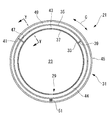
図3は、図2のX−X断面図である。図4は、図3のY−Y断面図である。
減衰装置21には、音響ライナ29と、音響ダンパ31と、が備えられている。
音響ライナ23には、燃焼筒19の一部を構成する筒状をした板部(多孔板部)33と、ライナカバー(カバー部材)35と、が備えられている。
3 is a cross-sectional view taken along the line XX of FIG. 4 is a YY cross-sectional view of FIG.
The
The
板部33には、円筒形状をした多数(複数)の貫通孔37が略全周に亘り形成されている。
貫通孔37は、軸線方向Lおよび周方向Cに、互いに間隔を開けて列をなして複数形成されている。
また、貫通孔37は全て同一形状としてもよいし、後述する第1音響ダンパ共鳴空間43と音響ライナ共鳴空間44とで、各々別形状としてもよく、特に限定されるものではない。
A large number (plural) of through
A plurality of through
The through holes 37 may all have the same shape, or may be different shapes in a first acoustic
ライナカバー35は、内周側が開放されたU字状の断面形状をしたリング状部材である。ライナカバー35は、板部33の外周側にその全周囲を囲繞するように設けられている。
ライナカバー35の開放部の軸線方向L長さは、貫通孔37が形成されている範囲よりも大きくされている。
ライナカバー35は、U字状の断面形状の開放側端部が板部33に、たとえば、ロウ付けによって接合されている。なお、ライナカバー35の取り付けは溶接を用いてもよい。
The
The length L in the axial direction of the open portion of the
The
これにより、ライナカバー35は板部33の外側の面との間に空間を形成している。この空間の周方向Cは、第1仕切板39と第2仕切板41とによって仕切られている。
図3において、板部33、ライナカバー35、第1仕切板39および第2仕切板42によって囲まれた上部の全周の約三分の一に亘る空間が第1音響ダンパ共鳴空間43となり、下部の約三分の二に亘る範囲が音響ライナ共鳴空間44となる。
Thereby, the
In FIG. 3, a space covering about one third of the entire circumference of the upper part surrounded by the
音響ダンパ31には、ダンパカバー(音響部)45とライナカバー35に設けられた開口部47とが備えられている。
ダンパカバー45は、内周側が開放されたU字状の断面形状をしたリング状部材である。ダンパカバー45は、ライナカバー35の外周側にその略全周囲を囲繞するように設けられている。
ダンパカバー45の開放部の軸線方向L長さは、図4に示されるように蒸気排出流路27およびライナカバー35が形成されている範囲よりも大きくされている。
なお、前述したように、燃焼筒19の冷却媒体として空気を用いる場合は、蒸気排出流路27は不要となり、ダンパカバー45はライナカバー35を囲繞する十分な大きさとすればよい。
ダンパカバー45は、U字状の断面形状の開放側端部が板部33(燃焼筒19)に、たとえば、ロウ付けによって接合されている。なお、ダンパカバー45の取り付けは溶接を用いてもよい。
The
The damper cover 45 is a ring-shaped member having a U-shaped cross-section with an inner peripheral side opened. The damper cover 45 is provided on the outer peripheral side of the
The length L in the axial direction of the opening portion of the
As described above, when air is used as the cooling medium for the
The damper cover 45 has a U-shaped cross-sectional open end that is joined to the plate 33 (combustion cylinder 19) by, for example, brazing. The damper cover 45 may be attached by welding.
これにより、ダンパカバー45は板部33の外側の面との間に空間を形成している。この空間の周方向Cは、第2仕切板41によって仕切られている。
板部33、ダンパカバー45、ライナカバー35の外側面、蒸気排出流路27の外側面および第2仕切板41によって囲まれた空間は、第2音響ダンパ共鳴空間49として形成される。
第2音響ダンパ共鳴空間49は全周に亘り設けられ、かつ、横断面積も大きいので、音響ライナ共鳴空間44よりも格段に大きな容積(全長)を有している。
なお、本実施形態においては、第2仕切板41は、第1音響ダンパ共鳴空間43と音響ライナ共鳴空間44とを仕切る共用部材となっているが、それぞれに必要な共鳴空間の容積(全長)を確保するために、必要に応じて第2仕切板41を別部材としてもよい。
Thereby, the damper cover 45 forms a space between the outer surface of the
A space surrounded by the
Since the second acoustic
In the present embodiment, the
開口部47は、ライナカバー35における第2仕切板41の近傍位置に設けられている。開口部47は、軸方向Lに細長い略矩形状をし、ライナカバー35を貫通するようにされている。
第2音響ダンパ共鳴空間49は、開口部47を介して第1音響ダンパ共鳴空間43と連通している。第1音響ダンパ共鳴空間43は、貫通孔37を介して燃焼領域23と連通しているので、第2音響ダンパ共鳴空間49は燃焼領域23と連通していることになり、一体の音響ダンパ31として作用する。
The
The second acoustic
このように、ダンパカバー45は、燃焼筒19に沿って、周方向Cに延在するように設置されているので、ダンパカバー45は燃焼筒19の周方向Cの一定箇所に集中することなく、周方向Cに広く配置されることになる。
これにより、ダンパカバー45は燃焼筒19の外周側への突起が抑制されるので、燃焼器5の外側に必要な空間を削減することができる。
したがって、車室13を小さくできるので、それを形成するハウジング11を小型化することができる。このため、たとえば、ガスタービン1を陸上輸送可能な寸法とすることができるので、輸送コストを含め、製造コストを低減させることができる。
また、音響ライナ29の一部を構成するライナカバー35を音響ダンパ31の構成部材と兼用して一体に形成することにより、音響ダンパ31を燃焼筒19とは別体に形成した場合と比べ、材料が少なくなるので、音響ダンパ31の製造コストを低減させることができる。
Thus, since the
Thereby, since the
Therefore, since the
In addition, by forming the
また、ダンパカバー45の燃焼筒19外周側への突起が小さくなると、たとえば、燃焼器5の取付部分を若干大きくする等によって、あるいは、そのままの状態でも音響ダンパ31と一体として燃焼器5を引き出すことできる。これにより、燃焼器5の取出作業が簡素化されるので、燃焼器5のメンテナンス性を向上させることができる。
Further, when the protrusion of the
第2音響ダンパ共鳴空間49には、多孔質金属(流体抵抗部材)51が設けられている。この多孔質金属51は、ポーラス状の金属、すなわち、小さな孔が多数形成されている金属である。多孔質金属51は、ダンパカバー45の一部に、ダンパカバー45の内部空間の形状と略同形状となって第2音響ダンパ共鳴空間49に設けられている。
なお、多孔質金属51は、必要に応じて用いられるものであり、これを省略することは可能である。
A porous metal (fluid resistance member) 51 is provided in the second acoustic
The
タービン部7は、図1に示すように、燃焼器5により生成された高温ガスの供給を受けて回転駆動力を発生させ、発生した回転駆動力を回転軸9に伝達するものである。
回転軸9は、図1に示すように、回転軸線まわりに回転可能に支持される円柱状の部材であり、タービン部7により発生された回転駆動力を圧縮機3に伝達するものである。
なお、タービン部7および回転軸9としては、公知の構成を用いることができ、特にその構成を限定するものではない。
As shown in FIG. 1, the turbine unit 7 receives the supply of the high-temperature gas generated by the combustor 5 to generate a rotational driving force, and transmits the generated rotational driving force to the rotating shaft 9.
As shown in FIG. 1, the rotating shaft 9 is a columnar member that is rotatably supported around the rotating axis, and transmits the rotational driving force generated by the turbine unit 7 to the compressor 3.
In addition, as a turbine part 7 and the rotating shaft 9, a well-known structure can be used and the structure in particular is not limited.
次に、上記のとおり構成されたガスタービン1の作用・効果について説明する。
ガスタービン1は、図1に示すように、圧縮機3が回転駆動されることにより大気(空気)を吸入する。吸入された大気は、圧縮機3により圧縮されるとともに、燃焼器5に向かって送り出される。
燃焼器5に流入された圧縮された空気は、燃焼器5において外部から供給された燃料と混合される。空気および燃料の混合気は燃焼器5において燃焼され、燃焼熱により高温の燃焼ガスが生成される。
燃焼器5において生成された燃焼ガスは、燃焼器5から下流のタービン部7に供給される。タービン部7は高温ガスにより回転駆動され、その回転駆動力は回転軸9に伝達される。回転軸9は、タービン部7において抽出された回転駆動力を圧縮機3などに伝達する。
Next, operations and effects of the
As shown in FIG. 1, the
The compressed air flowing into the combustor 5 is mixed with fuel supplied from the outside in the combustor 5. The air / fuel mixture is combusted in the combustor 5, and high-temperature combustion gas is generated by the combustion heat.
The combustion gas generated in the combustor 5 is supplied from the combustor 5 to the downstream turbine unit 7. The turbine unit 7 is rotationally driven by the high-temperature gas, and the rotational driving force is transmitted to the rotary shaft 9. The rotating shaft 9 transmits the rotational driving force extracted in the turbine unit 7 to the compressor 3 and the like.
燃焼器5で燃料が燃焼されると、その燃焼によって燃焼振動が発生する場合がある。
特に、排出ガスの低NOx化を図るため燃料を希薄燃焼させると、燃焼が不安定になり易く、燃焼振動が発生し易くなる。
このように燃焼振動が発生すると、燃焼振動による空気振動(圧力波)が板部33の貫通孔37に入る。
音響ライナ29における音響ライナ共鳴空間44内の空気と貫通孔37内の空気とは、音響ライナ共鳴空間44内の空気がバネとして機能することにより共鳴系を構成している。このため、板部33の内側で発生した燃焼振動による空気振動、あるいは音のうち、音響ライナ共鳴空間44の容積(全長)や貫通孔37の全長に応じた周波数領域の音に対して貫通孔37内の空気が激しく振動し、共鳴するので、空気と貫通孔37の表面との摩擦によって、この共鳴周波数の音が吸音される。これにより、燃焼振動の振幅が減衰されて燃焼振動による音が低減する。
When fuel is burned in the combustor 5, combustion vibration may occur due to the combustion.
In particular, when the fuel is lean burned in order to reduce the NOx emission, the combustion tends to become unstable and combustion vibrations are likely to occur.
When combustion vibration occurs in this way, air vibration (pressure wave) due to combustion vibration enters the through
The air in the acoustic
第1音響ダンパ共鳴空間43と第2音響ダンパ共鳴空間49とは、開口部47を介して接続されている。このため、燃焼領域23で発生した燃焼振動は、第1音響ダンパ共鳴空間43を介して第2音響ダンパ共鳴空間49に伝達され、一体の音響ダンパ31として作用する。
この音響ダンパ31は、音響ライナ共鳴空間44よりも大きな容積(全長)を有している。このため、音響ダンパ31の共鳴空間(第1音響ダンパ共鳴空間43および第2音響ダンパ共鳴空間49)では、音響ライナ共鳴空間44で減衰する振動の波長よりも長い波長の振動、すなわち、音響ライナ共鳴空間44で減衰することのできる振動の周波数領域よりも低い周波数領域の振動を減衰することができる。
The first acoustic
The
このように、音響ライナ29と音響ダンパ31とは、双方とも振動を減衰する作用を有するが、音響ライナ29は比較的高い周波数領域の振動を減衰し、音響ダンパ31は比較的低い周波数領域の振動を減衰する。
音響ライナ29と音響ダンパ31とをそれぞれ設置することにより、複数の周波数領域の振動を減衰することができる、あるいは、広い周波数領域の振動を減衰することができる。
したがって、燃焼器5における燃焼時に発生する騒音を効果的に低減することができる。
As described above, both the
By installing the
Therefore, noise generated during combustion in the combustor 5 can be effectively reduced.
冷却通路25内には、ボイラから蒸気が供給され、蒸気排出流路27から系外に排出される。蒸気が冷却通路25を流れる際に燃焼筒19(板部33)と熱交換が行なわれ、燃焼筒19は冷却される。これにより、ガスタービン1運転中の燃焼筒19は冷却される。
ガスタービン1運転中、貫通孔37には、燃焼ガスが侵入することがある。貫通孔37に燃焼ガスが侵入すると燃焼ガスによって加熱されるので、周囲との温度差によって熱応力が大きくなる。
板部33は、冷却通路25を通る蒸気によって冷却されているので、貫通孔37の周囲が十分に冷却される。これにより、この熱応力の上昇を抑制することができる。
Steam is supplied from the boiler into the
During operation of the
Since the
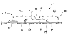
図5は、本実施形態の第1変形例にかかる減衰装置21を示す要部断面図である。本変形例の減衰装置21では、図5に示されるように、軸線方向Lに分離した2個の音響ダンパ31A,31Bが設けられている。2個のダンパカバー45A,45Bの軸線方向Lの各一端部は、それぞれライナカバー35の外表面に接合されている。ライナカバー35には、ダンパカバー45A,45Bに覆われた部分にそれぞれ開口部47A,47Bが形成されている。
ダンパカバー45A,45Bはそれぞれ周方向Cの長さ(共鳴空間の全長)を変えるか、多孔質金属51の周方向Cの取付位置を変える、あるいはその両方により、吸収できる振動の周波数を変えることができる。
FIG. 5 is a cross-sectional view of a main part showing an
The damper covers 45A and 45B each change the frequency of vibration that can be absorbed by changing the length in the circumferential direction C (the total length of the resonance space), changing the mounting position of the
このようにすると、複数の音響ダンパ31A,31Bによって振動を減衰できるので、より確実に減衰させることができる。また、2個の音響ダンパ31A,31Bはそれぞれ減衰する周波数領域が異なるので、比較的低い周波数領域における複数の周波数領域の振動を減衰することができる、あるいは、広い周波数領域の振動を減衰することができる。
したがって、音響ダンパ31A,31Bによる振動の減衰性能を、より確実に向上させることができる。
In this way, the vibration can be attenuated by the plurality of
Therefore, the vibration damping performance by the
なお、本実施形態では、第2音響ダンパ共鳴空間49は略全周に亘るように形成されているが、これに限定されない。これは、目的とする周波数領域に応じて設定される容積(全長)を有するようにすればよいので、全周でなく、途中まででもよい。
In the present embodiment, the second acoustic
〔第2実施形態〕
次に、本発明の第2実施形態について図6および図7を参照して説明する。
本実施形態のガスタービンの基本構成は、第1実施形態と同様であるが、第1実施形態とは、減衰装置21の構成が異なっている。よって、本実施形態においては、異なる減衰装置21について主として説明し、その他の構成要素等については重複した説明を省略する。
図6は、本実施形態のガスタービン1の燃焼器5における減衰装置21の構成を説明する要部断面図である。図7は、図6のZ−Z断面図である。
なお、第1実施形態と同一の構成要素には、同一の符号を付してその説明を省略する。
[Second Embodiment]
Next, a second embodiment of the present invention will be described with reference to FIGS.
The basic configuration of the gas turbine of this embodiment is the same as that of the first embodiment, but the configuration of the damping
FIG. 6 is a cross-sectional view of the main part for explaining the configuration of the damping
In addition, the same code | symbol is attached | subjected to the component same as 1st Embodiment, and the description is abbreviate | omitted.
本実施形態では、ダンパカバー(音響部)53は、略矩形状の断面形状をし、リングの一部を形成するように湾曲された箱体である。ダンパカバー53は、図6に示されるように、ライナカバー35の外周側にその周囲を覆うように設けられている。
ダンパカバー53は、周方向Cの一部が切り欠かれているが、この切欠部の少なくとも一部は第1音響ダンパ共鳴空間43の設置位置と重なるようにされている。
ダンパカバー53の内周面には、周方向Cに延在するダンパ溝55が形成されている。ダンパ溝55は、ダンパカバー53の略全長に亘り設けられている。ダンパ溝55の外周部は、外側に突出する壁部で構成されている。
In the present embodiment, the damper cover (sound part) 53 is a box that has a substantially rectangular cross-sectional shape and is curved so as to form a part of the ring. As shown in FIG. 6, the
The damper cover 53 is partly cut away in the circumferential direction C, and at least part of the cutout part overlaps with the installation position of the first acoustic
A
ダンパカバー53の軸線方向L長さ、すなわち、幅は、ライナカバー35よりも相当大きくされている。ダンパ溝55の軸線方向L長さは、図7に示されるようにライナカバー35よりも小さくされている。
ダンパカバー53は、ダンパ溝55の壁部がライナカバー35に、たとえば、ロウ付けによって接合されている。なお、ダンパカバー53の取り付けは溶接を用いてもよい。
ダンパカバー53は、図7に示されるように板部33(燃焼筒19)と接触しないように間隔が空けられて装着される。
The length L in the axial direction of the
In the
As shown in FIG. 7, the
これにより、ダンパカバー53はライナカバー35の外側の面との間に空間を形成している。この空間は、第2音響ダンパ共鳴空間57として形成される。
第2音響ダンパ共鳴空間57は略全周に亘り設けられ、かつ、横断面積も大きいので、音響ライナ共鳴空間44よりも格段に大きな容積(全長)を有している。
ダンパカバー53の周方向C長さは、目的とする周波数領域に応じて設定される容積(全長)を確保できるように設定される。
Thereby, the damper cover 53 forms a space between the outer surface of the
Since the second acoustic
The circumferential direction C length of the
ライナカバー35には、ダンパカバー53の一方の周端部の近傍位置に開口部59が設けられている。開口部59は、軸方向Lに細長い略矩形状をし、ライナカバー35を貫通するようにされている。
第2音響ダンパ共鳴空間57は、開口部59を介して第1音響ダンパ共鳴空間43と連通している。第1音響ダンパ共鳴空間43は、貫通孔37を介して燃焼領域23と連通しているので、第2音響ダンパ共鳴空間57は燃焼領域23と連通し、一体の音響ダンパ31として作用することになる。
The
The second acoustic
このように、ダンパカバー53は、ライナカバー35、すなわち、燃焼筒19に沿って、周方向Cに延在するように設置されているので、ダンパカバー53は燃焼筒19の周方向Cの一定箇所に集中することなく、周方向Cに広く配置されることになる。
これにより、ダンパカバー53は燃焼筒19の外周側への突起が抑制されるので、燃焼器5の外側に必要な空間を削減することができる。
したがって、車室13を小さくできるので、それを形成するハウジング11を小型化することができる。このため、たとえば、ガスタービン1を陸上輸送が十分可能な寸法とすることができるので、輸送コストを含め、製造コストを低減させることができる。
Thus, since the
Thereby, since the
Therefore, since the
ダンパカバー53の燃焼筒19外周側への突起が小さくなると、たとえば、燃焼器5の取付部分を若干大きくする等によって、あるいは、そのままの状態でも音響ダンパ31と一体として燃焼器5を引き出すことできる。これにより、燃焼器5の取出作業が簡素化されるので、燃焼器5のメンテナンス性を向上させることができる。
本実施形態では、ダンパカバー53は、燃焼器5の運転によって加熱される板部33(燃焼筒19)から間隔を空けるように装着されているので、第1実施形態のダンパカバー45に比べて熱応力を緩和することができる。
ダンパカバー53は、ライナカバー35の全てを覆わないように取り付けられているので、パージ空気をライナカバー35内の音響ライナ共鳴空間44に容易に供給することができる。
When the protrusion of the
In the present embodiment, the
Since the
〔第3実施形態〕
次に、本発明の第3実施形態について図8および図9を参照して説明する。
本実施形態のガスタービンの基本構成は、第1実施形態と同様であるが、第1実施形態とは、減衰装置21の構成が異なっている。よって、本実施形態においては、異なる減衰装置21について主として説明し、その他の構成要素等については重複した説明を省略する。
図8は、本実施形態のガスタービン1の燃焼器5における減衰装置21の構成を説明する要部断面図である。図9は、図8のW−W断面図である。
なお、第1実施形態と同一の構成要素には、同一の符号を付してその説明を省略する。
[Third Embodiment]
Next, a third embodiment of the present invention will be described with reference to FIGS.
The basic configuration of the gas turbine of this embodiment is the same as that of the first embodiment, but the configuration of the damping
FIG. 8 is a cross-sectional view of a main part for explaining the configuration of the damping
In addition, the same code | symbol is attached | subjected to the component same as 1st Embodiment, and the description is abbreviate | omitted.
音響ダンパ31には、ダンパカバー(音響部)61とライナカバー35に設けられた開口部63とが備えられている。
ダンパカバー61は、図9に示されるように内周側が開放された矩形状の断面形状をし、リングの一部(たとえば、略160度の範囲)を形成するように湾曲されている。ダンパカバー61には、図8に示されるように、湾曲に沿った方向で、高さの異なる小径部分65と、大径部分67とが備えられている。大径部分65の両端部は、端板69,71によって封鎖されている。小径部分65の端部は、端板73によって封鎖されている。
The
As shown in FIG. 9, the
小径部分65の大径部分67側端部は、端板71を越えて端板69の近くまで大径部分67内に入り込んでいる。
大径部分67内には、小径部分65よりも外側の空間を仕切る周方向の仕切板75が設けられている。周方向の仕切板75の一端は、端板69に固定され、他端は端板71の近くまで延びている。
ダンパカバー61の開放部の軸線方向L長さは、図9に示されるようにライナカバー35よりも短くされている。
ダンパカバー61は、U字状の断面形状の開放側端部がライナカバー35に、たとえば、ロウ付けによって接合されている。なお、ダンパカバー61の取り付けは溶接を用いてもよい。
The end of the
In the large-
The length L in the axial direction of the opening portion of the
The damper cover 61 is joined to the
これにより、ダンパカバー61はライナカバー35の外側の面との間に空間を形成している。この空間は、第2音響ダンパ共鳴空間77として形成される。
第2音響ダンパ共鳴空間77は、小径部分65の内側で形成される第1空間、小径部分65の外側と周方向の仕切板75の内側とで形成される第2空間および周方向の仕切板75の外側と大径部分67の内側とで形成される第3空間で形成される。
第1空間と第2空間とは、端板69の近傍で連通している。第2空間と第3空間とは、端板69の近傍で連通している。これにより、第2音響ダンパ共鳴空間77は、2回折り返されて形成されていることになる。
Thereby, the damper cover 61 forms a space between the outer surface of the
The second acoustic
The first space and the second space communicate with each other in the vicinity of the
第2音響ダンパ共鳴空間77は、周方向Cで略160度の範囲に亘って設けられているだけであるが、2回折り返されているので、第2音響ダンパ共鳴空間77として十分な容積(全長)を確保することができる。
第2音響ダンパ共鳴空間77は、横断面積も大きいこともあいまって、音響ライナ共鳴空間44よりも格段に大きな容積(全長)を有している。
The second acoustic
The second acoustic
開口部63は、ライナカバー35における端板73の近傍位置に設けられている。言い換えると、開口部63は第2音響ダンパ共鳴空間77の一端部に位置している。
開口部63は、軸方向Lに細長い略矩形状をし、ライナカバー35を貫通するようにされている。
第2音響ダンパ共鳴空間77は、開口部63を介して第1音響ダンパ共鳴空間43と連通している。第1音響ダンパ共鳴空間43は、貫通孔37を介して燃焼領域23と連通しているので、第2音響ダンパ共鳴空間77は燃焼領域23と連通していることになり、一体の音響ダンパ31として作用する。
The
The
The second acoustic
このように、ダンパカバー61は、燃焼筒19に沿って、周方向Cに延在するように設置されているので、ダンパカバー61は、燃焼筒19の周方向Cに比較的広く配置されることになる。
これにより、ダンパカバー61は燃焼筒19の外周側への突起が抑制されるので、燃焼器5の外側に必要な空間を削減することができる。
したがって、車室13を小さくできるので、それを形成するハウジング11を小型化することができる。このため、たとえば、ガスタービン1を陸上輸送が十分可能な寸法とすることができるので、輸送コストを含め、製造コストを低減させることができる。
Thus, since the
Thereby, since the
Therefore, since the
また、ダンパカバー61の燃焼筒19外周側への突起が小さくなると、たとえば、燃焼器5の取付部分を若干大きくする等によって、あるいは、そのままの状態でも音響ダンパ31と一体として燃焼器5を引き出すことできる。これにより、燃焼器5の取出作業が簡素化されるので、燃焼器5のメンテナンス性を向上させることができる。
ダンパカバー61は、周方向Cの略半周以下を覆っているだけであるので、残りの半周以上の部分には、別の部材を設置することができる。
Further, when the protrusion of the
Since the
この場合、図10に示すように、2個の音響ダンパ31A,31Bを設けるようにできる。2個の音響ダンパ31A,31Bは、それぞれのダンパカバー61A,61Bの小径部分65A,65Bが対向するように設置される。小径部分65A,65Bは、それぞれライナカバー35の外表面に接合されている。ライナカバー35には、ダンパカバー61A,61Bに覆われた部分にそれぞれ開口部63A,63Bが形成されている。
In this case, as shown in FIG. 10, two
このようにすると、複数の音響ダンパ31A,31Bによって振動を減衰できるので、より確実に減衰させることができる。
したがって、音響ダンパ31A,31Bによる振動の減衰性能を、より確実に向上させることができる。
また、2個の音響ダンパ77A,77Bの容積(周方向Cの長さ、つまり共鳴空間の全長)を異ならせるようにしてもよいし、多孔質金属51A,51Bの取付位置を変えてもよい。このようにすると、それぞれ減衰する周波数領域の異なる2個の音響ダンパ31A,31Bが形成されるので、比較的低い周波数領域における複数の周波数領域の振動を減衰することができる、あるいは、広い周波数領域の振動を減衰することができる。
In this way, the vibration can be attenuated by the plurality of
Therefore, the vibration damping performance by the
Moreover, the volume (the length in the circumferential direction C, that is, the total length of the resonance space) of the two
なお、本発明は上述した各実施形態に限定されることはなく、その要旨を逸脱しない範囲内において適宜変更することができる。 In addition, this invention is not limited to each embodiment mentioned above, In the range which does not deviate from the summary, it can change suitably.
たとえば、上述した各実施形態では、音響ダンパ31は、音響ライナ29と一体的に構成されているが、これは独立させて、それぞれ燃焼筒19に取り付けるようにしてもよい。このようにすると、音響ダンパ31の外周側への突出量を一層低減することができる。
この場合、音響ダンパ共鳴空間49,57,77は、それぞれ直接燃焼領域23と連通することになる。
For example, in each of the above-described embodiments, the
In this case, the acoustic
1 ガスタービン
3 圧縮機
7 タービン
19 燃焼筒
23 燃焼領域
29 音響ライナ
31,31A,31B 音響ダンパ
33 板部
35 カバー
37 貫通孔
43 第1音響ダンパ共鳴空間
44 音響ライナ共鳴空間
45,53,61 ダンパカバー
49,57,77 第2音響ダンパ共鳴空間
51,51A,51B 多孔質金属(流体抵抗部材)
53,55 溝部
L 軸線方向
DESCRIPTION OF
53,55 Groove L Axial direction
Claims (6)
該燃焼領域に連通する音響ダンパ共鳴空間を有する音響部を有する音響ダンパと、を備える燃焼器であって、
前記音響部は、前記筒体に沿って、前記筒体の軸線方向に対して交差する方向に延在するように設置されており、
前記筒体を構成し、厚さ方向に貫通する複数の貫通孔が設けられている多孔板部と該多孔板部の周囲に間隔を空けて覆うように設けられたカバー部材とによって形成される空間を、仕切り部材によって前記筒体の周方向に複数の空間に分割し、
分割された前記複数の空間のうちの少なくとも一つが、前記音響ダンパ共鳴空間の一部となり、
分割された前記複数の空間のうちの他の少なくとも一つが、音響ライナ共鳴空間となっている燃焼器。 A cylinder that forms a combustion zone therein;
An acoustic damper having an acoustic part having an acoustic damper resonance space communicating with the combustion region, and a combustor comprising:
The acoustic part is installed so as to extend along the cylindrical body in a direction intersecting the axial direction of the cylindrical body,
The cylindrical body is formed by a perforated plate portion provided with a plurality of through holes penetrating in the thickness direction, and a cover member provided so as to cover the perforated plate portion with a space therebetween. The space is divided into a plurality of spaces in the circumferential direction of the cylindrical body by a partition member,
At least one of the plurality of divided spaces becomes a part of the acoustic damper resonance space,
A combustor in which at least one of the divided spaces is an acoustic liner resonance space.
Priority Applications (1)
| Application Number | Priority Date | Filing Date | Title |
|---|---|---|---|
| JP2013039522A JP5502217B2 (en) | 2009-02-27 | 2013-02-28 | Combustor and gas turbine provided with the same |
Applications Claiming Priority (3)
| Application Number | Priority Date | Filing Date | Title |
|---|---|---|---|
| JP2009047358 | 2009-02-27 | ||
| JP2009047358 | 2009-02-27 | ||
| JP2013039522A JP5502217B2 (en) | 2009-02-27 | 2013-02-28 | Combustor and gas turbine provided with the same |
Related Parent Applications (1)
| Application Number | Title | Priority Date | Filing Date |
|---|---|---|---|
| JP2011501455A Division JP5291790B2 (en) | 2009-02-27 | 2009-10-15 | Combustor and gas turbine provided with the same |
Publications (2)
| Publication Number | Publication Date |
|---|---|
| JP2013117231A true JP2013117231A (en) | 2013-06-13 |
| JP5502217B2 JP5502217B2 (en) | 2014-05-28 |
Family
ID=42665202
Family Applications (2)
| Application Number | Title | Priority Date | Filing Date |
|---|---|---|---|
| JP2011501455A Active JP5291790B2 (en) | 2009-02-27 | 2009-10-15 | Combustor and gas turbine provided with the same |
| JP2013039522A Active JP5502217B2 (en) | 2009-02-27 | 2013-02-28 | Combustor and gas turbine provided with the same |
Family Applications Before (1)
| Application Number | Title | Priority Date | Filing Date |
|---|---|---|---|
| JP2011501455A Active JP5291790B2 (en) | 2009-02-27 | 2009-10-15 | Combustor and gas turbine provided with the same |
Country Status (6)
| Country | Link |
|---|---|
| US (1) | US8490744B2 (en) |
| EP (1) | EP2402658B1 (en) |
| JP (2) | JP5291790B2 (en) |
| KR (1) | KR101285930B1 (en) |
| CN (2) | CN102165263B (en) |
| WO (1) | WO2010097982A1 (en) |
Cited By (6)
| Publication number | Priority date | Publication date | Assignee | Title |
|---|---|---|---|---|
| JP2014238099A (en) * | 2011-03-22 | 2014-12-18 | 三菱重工業株式会社 | Combustion chamber and gas turbine |
| WO2015151880A1 (en) * | 2014-03-31 | 2015-10-08 | 三菱日立パワーシステムズ株式会社 | Combustor, gas turbine provided with same, and method for repairing combustor |
| WO2017006971A1 (en) * | 2015-07-08 | 2017-01-12 | 三菱日立パワーシステムズ株式会社 | Combustor and gas turbine |
| JP2018159533A (en) * | 2017-03-24 | 2018-10-11 | 三菱日立パワーシステムズ株式会社 | Resonant sound absorber for gas turbine combustor, gas turbine combustor provided with the same, and gas turbine |
| KR20220061238A (en) | 2019-12-24 | 2022-05-12 | 미츠비시 파워 가부시키가이샤 | A combustor component, a combustor provided with this combustor component, and a gas turbine provided with this combustor |
| WO2022202516A1 (en) * | 2021-03-24 | 2022-09-29 | 三菱重工業株式会社 | Combustor for gas turbine, gas turbine, and gas turbine assembly method |
Families Citing this family (52)
| Publication number | Priority date | Publication date | Assignee | Title |
|---|---|---|---|---|
| JP4929357B2 (en) * | 2007-11-21 | 2012-05-09 | 三菱重工業株式会社 | Damping device and gas turbine combustor |
| EP2385303A1 (en) * | 2010-05-03 | 2011-11-09 | Alstom Technology Ltd | Combustion Device for a Gas Turbine |
| DE102010049578A1 (en) * | 2010-10-26 | 2012-04-26 | Webasto Ag | Silencer device for a fluid line and heater with a silencer device |
| WO2013125683A1 (en) * | 2012-02-24 | 2013-08-29 | 三菱重工業株式会社 | Acoustic damper, combustor and gas turbine |
| US8684130B1 (en) * | 2012-09-10 | 2014-04-01 | Alstom Technology Ltd. | Damping system for combustor |
| KR20150074155A (en) | 2012-10-24 | 2015-07-01 | 알스톰 테크놀러지 리미티드 | Sequential combustion with dilution gas mixer |
| EP2762784B1 (en) | 2012-11-30 | 2016-02-03 | Alstom Technology Ltd | Damping device for a gas turbine combustor |
| JP6066754B2 (en) * | 2013-02-07 | 2017-01-25 | 三菱重工業株式会社 | Acoustic damper, combustor, gas turbine, and method for changing target frequency of acoustic damper |
| FR3002002B1 (en) * | 2013-02-12 | 2016-11-25 | Avon Polymeres France Sas | ACOUSTIC RESONATOR WITH EXCENTREE ROOM |
| US20140245746A1 (en) * | 2013-03-04 | 2014-09-04 | General Electric Company | Combustion arrangement and method of reducing pressure fluctuations of a combustion arrangement |
| GB2516286B (en) * | 2013-07-18 | 2016-08-17 | Rolls Royce Plc | A duct and method for damping pressure waves caused by thermoacoustic instability |
| US9410484B2 (en) * | 2013-07-19 | 2016-08-09 | Siemens Aktiengesellschaft | Cooling chamber for upstream weld of damping resonator on turbine component |
| US20150082794A1 (en) * | 2013-09-26 | 2015-03-26 | Reinhard Schilp | Apparatus for acoustic damping and operational control of damping, cooling, and emissions in a gas turbine engine |
| EP2865948B1 (en) | 2013-10-25 | 2018-04-11 | Ansaldo Energia Switzerland AG | Gas turbine combustor having a quarter wave damper |
| JP6266106B2 (en) * | 2013-11-11 | 2018-01-24 | コーニンクレッカ フィリップス エヌ ヴェKoninklijke Philips N.V. | Robust ultrasonic transducer probe with protected integrated circuit interconnection |
| US9625158B2 (en) * | 2014-02-18 | 2017-04-18 | Dresser-Rand Company | Gas turbine combustion acoustic damping system |
| JP6456481B2 (en) * | 2014-08-26 | 2019-01-23 | シーメンス エナジー インコーポレイテッド | Film cooling hole array for an acoustic resonator in a gas turbine engine |
| JP6623485B2 (en) * | 2014-09-25 | 2019-12-25 | 三菱日立パワーシステムズ株式会社 | Combustor and gas turbine including the same |
| US9988958B2 (en) * | 2014-12-01 | 2018-06-05 | Siemens Aktiengesellschaft | Resonators with interchangeable metering tubes for gas turbine engines |
| EP3037725B1 (en) | 2014-12-22 | 2018-10-31 | Ansaldo Energia Switzerland AG | Mixer for admixing a dilution air to the hot gas flow |
| EP3037726B1 (en) | 2014-12-22 | 2018-09-26 | Ansaldo Energia Switzerland AG | Separate feedings of cooling and dilution air |
| EP3037728B1 (en) | 2014-12-22 | 2020-04-29 | Ansaldo Energia Switzerland AG | Axially staged mixer with dilution air injection |
| EP3048370A1 (en) * | 2015-01-23 | 2016-07-27 | Siemens Aktiengesellschaft | Combustion chamber for a gas turbine engine |
| EP3051206B1 (en) | 2015-01-28 | 2019-10-30 | Ansaldo Energia Switzerland AG | Sequential gas turbine combustor arrangement with a mixer and a damper |
| CN107250491B (en) * | 2015-02-23 | 2019-08-16 | 三菱重工业株式会社 | Attenuating device, burner and gas turbine |
| TWI557375B (en) * | 2015-02-25 | 2016-11-11 | Mitsubishi Heavy Ind Ltd | Vibration dampers, burners and gas turbines |
| WO2016143230A1 (en) * | 2015-03-06 | 2016-09-15 | 三菱重工業株式会社 | Sealing device for gas turbine, gas turbine, and aircraft engine |
| US9783316B2 (en) * | 2015-06-22 | 2017-10-10 | Rohr, Inc. | Acoustic panel assembly with a folding chamber |
| US10513984B2 (en) | 2015-08-25 | 2019-12-24 | General Electric Company | System for suppressing acoustic noise within a gas turbine combustor |
| JP6679273B2 (en) * | 2015-11-02 | 2020-04-15 | 三菱重工業株式会社 | Combustor and rocket engine |
| US10197275B2 (en) | 2016-05-03 | 2019-02-05 | General Electric Company | High frequency acoustic damper for combustor liners |
| US10935242B2 (en) | 2016-07-07 | 2021-03-02 | General Electric Company | Combustor assembly for a turbine engine |
| US10619854B2 (en) * | 2016-11-30 | 2020-04-14 | United Technologies Corporation | Systems and methods for combustor panel |
| US10428765B2 (en) * | 2017-03-07 | 2019-10-01 | United Technologies Corporation | Asymmetric multi degree of freedom flutter damper |
| US10428685B2 (en) | 2017-03-07 | 2019-10-01 | United Technologies Corporation | Flutter inhibiting intake for gas turbine propulsion system |
| US10415506B2 (en) * | 2017-03-07 | 2019-09-17 | United Technologies Corporation | Multi degree of freedom flutter damper |
| US10539156B2 (en) | 2017-03-07 | 2020-01-21 | United Technologies Corporation | Variable displacement flutter damper for a turbofan engine |
| US10619566B2 (en) | 2017-03-07 | 2020-04-14 | United Technologies Corporation | Flutter damper for a turbofan engine |
| US10612464B2 (en) | 2017-03-07 | 2020-04-07 | United Technologies Corporation | Flutter inhibiting intake for gas turbine propulsion system |
| EP3372814B1 (en) * | 2017-03-07 | 2022-05-04 | Raytheon Technologies Corporation | Asymmetric multi degree of freedom flutter damper |
| US10422280B2 (en) | 2017-03-07 | 2019-09-24 | United Technologies Corporation | Fan flutter suppression system |
| US10941708B2 (en) | 2017-03-07 | 2021-03-09 | Raytheon Technologies Corporation | Acoustically damped gas turbine engine |
| JP7008722B2 (en) * | 2017-03-30 | 2022-01-25 | シーメンス アクティエンゲゼルシャフト | A system with a conduit arrangement for dual use of cooling fluid in the combustor section of a gas turbine engine |
| US10436118B2 (en) | 2017-06-19 | 2019-10-08 | Rohr, Inc. | Acoustic panel with folding chamber |
| US11536174B2 (en) | 2017-07-20 | 2022-12-27 | President And Fellows Of Harvard College | Acoustic damper for gas turbine combustors with orthogonal slots |
| EP3486566A1 (en) | 2017-11-15 | 2019-05-22 | Ansaldo Energia Switzerland AG | Gas turbine comprising a can combustor provided with a damper |
| CN110030578A (en) | 2017-11-15 | 2019-07-19 | 安萨尔多能源瑞士股份公司 | Barrel type burner for gas turbine and the gas turbine including this barrel type burner |
| DE102019205540A1 (en) | 2019-04-17 | 2020-10-22 | Siemens Aktiengesellschaft | Resonator, method for producing such and burner arrangement provided with such |
| JP7289752B2 (en) * | 2019-08-01 | 2023-06-12 | 三菱重工業株式会社 | Acoustic dampener, canister assembly, combustor, gas turbine and method of manufacturing canister assembly |
| JP7262364B2 (en) * | 2019-10-17 | 2023-04-21 | 三菱重工業株式会社 | gas turbine combustor |
| KR102343412B1 (en) * | 2020-10-06 | 2021-12-24 | 재단법인 파동에너지 극한제어 연구단 | Muffler |
| US20240003543A1 (en) * | 2022-06-29 | 2024-01-04 | General Electric Company | Acoustic liner for a gas turbine engine |
Citations (2)
| Publication number | Priority date | Publication date | Assignee | Title |
|---|---|---|---|---|
| JP2004183943A (en) * | 2002-12-02 | 2004-07-02 | Mitsubishi Heavy Ind Ltd | Gas turbine combustor and gas turbine equipped with the same |
| JP2006266671A (en) * | 2005-02-22 | 2006-10-05 | Mitsubishi Heavy Ind Ltd | Damping device, combustor and gas turbine |
Family Cites Families (11)
| Publication number | Priority date | Publication date | Assignee | Title |
|---|---|---|---|---|
| US4944362A (en) * | 1988-11-25 | 1990-07-31 | General Electric Company | Closed cavity noise suppressor |
| US6973790B2 (en) * | 2000-12-06 | 2005-12-13 | Mitsubishi Heavy Industries, Ltd. | Gas turbine combustor, gas turbine, and jet engine |
| JP3676228B2 (en) * | 2000-12-06 | 2005-07-27 | 三菱重工業株式会社 | Gas turbine combustor, gas turbine and jet engine |
| US6615576B2 (en) * | 2001-03-29 | 2003-09-09 | Honeywell International Inc. | Tortuous path quiet exhaust eductor system |
| WO2004051063A1 (en) * | 2002-12-02 | 2004-06-17 | Mitsubishi Heavy Industries, Ltd. | Gas turbine combustor, and gas turbine with the combustor |
| JP2005076982A (en) * | 2003-08-29 | 2005-03-24 | Mitsubishi Heavy Ind Ltd | Gas turbine combustor |
| JP4494889B2 (en) * | 2004-07-05 | 2010-06-30 | 三菱重工業株式会社 | Attenuation device |
| US7401682B2 (en) * | 2005-08-10 | 2008-07-22 | United Technologies Corporation | Architecture for an acoustic liner |
| FR2912186B1 (en) * | 2007-02-01 | 2013-07-05 | Airbus France | DEVICE FOR ACOUSTIC TREATMENT OF TURBINE NOISE AND COMBUSTION |
| FR2941495B1 (en) * | 2009-01-27 | 2017-09-29 | Turbomeca | SUSPENSION EXHAUST DUCT FOR TURBOMOTEUR |
| US8316813B2 (en) * | 2009-03-05 | 2012-11-27 | GM Global Technology Operations LLC | Engine assembly having variable intake air tuning device and tuning method |
-
2009
- 2009-10-15 KR KR1020117006442A patent/KR101285930B1/en active IP Right Grant
- 2009-10-15 EP EP09840829.7A patent/EP2402658B1/en active Active
- 2009-10-15 WO PCT/JP2009/067839 patent/WO2010097982A1/en active Application Filing
- 2009-10-15 CN CN200980137920.5A patent/CN102165263B/en active Active
- 2009-10-15 CN CN201410222369.7A patent/CN104033926B/en active Active
- 2009-10-15 US US13/121,874 patent/US8490744B2/en active Active
- 2009-10-15 JP JP2011501455A patent/JP5291790B2/en active Active
-
2013
- 2013-02-28 JP JP2013039522A patent/JP5502217B2/en active Active
Patent Citations (2)
| Publication number | Priority date | Publication date | Assignee | Title |
|---|---|---|---|---|
| JP2004183943A (en) * | 2002-12-02 | 2004-07-02 | Mitsubishi Heavy Ind Ltd | Gas turbine combustor and gas turbine equipped with the same |
| JP2006266671A (en) * | 2005-02-22 | 2006-10-05 | Mitsubishi Heavy Ind Ltd | Damping device, combustor and gas turbine |
Cited By (19)
| Publication number | Priority date | Publication date | Assignee | Title |
|---|---|---|---|---|
| JP2014238099A (en) * | 2011-03-22 | 2014-12-18 | 三菱重工業株式会社 | Combustion chamber and gas turbine |
| US10634345B2 (en) | 2014-03-31 | 2020-04-28 | Mitsubishi Hitachi Power Systems, Ltd. | Combustor, gas turbine provided with same, and method of repairing combustor |
| WO2015151880A1 (en) * | 2014-03-31 | 2015-10-08 | 三菱日立パワーシステムズ株式会社 | Combustor, gas turbine provided with same, and method for repairing combustor |
| JP2015197047A (en) * | 2014-03-31 | 2015-11-09 | 三菱日立パワーシステムズ株式会社 | Combustor, gas turbine with combustor and method for repairing combustor |
| KR20160113223A (en) | 2014-03-31 | 2016-09-28 | 미츠비시 히타치 파워 시스템즈 가부시키가이샤 | Combustor, gas turbine provided with same, and method for repairing combustor |
| US11022304B2 (en) | 2014-03-31 | 2021-06-01 | Mitsubishi Power, Ltd. | Combustor, gas turbine provided with same, and method of repairing combustor |
| DE112015001553B4 (en) * | 2014-03-31 | 2021-02-04 | Mitsubishi Power, Ltd. | Combustion chamber, gas turbine provided therewith, and method of repairing a combustion chamber |
| US10712004B2 (en) | 2015-07-08 | 2020-07-14 | Mitsubishi Hitachi Power Systems, Ltd. | Combustor including an acoustic device mounted on a combustion liner for damping combustion oscillation of a predetermined frequency and gas turbine |
| JP2017020682A (en) * | 2015-07-08 | 2017-01-26 | 三菱日立パワーシステムズ株式会社 | Combustor and gas turbine |
| WO2017006971A1 (en) * | 2015-07-08 | 2017-01-12 | 三菱日立パワーシステムズ株式会社 | Combustor and gas turbine |
| JP2018159533A (en) * | 2017-03-24 | 2018-10-11 | 三菱日立パワーシステムズ株式会社 | Resonant sound absorber for gas turbine combustor, gas turbine combustor provided with the same, and gas turbine |
| KR20220061238A (en) | 2019-12-24 | 2022-05-12 | 미츠비시 파워 가부시키가이샤 | A combustor component, a combustor provided with this combustor component, and a gas turbine provided with this combustor |
| DE112020005325T5 (en) | 2019-12-24 | 2022-08-04 | Mitsubishi Heavy Industries, Ltd. | COMBUSTOR COMPONENT, COMBUSTOR WITH THE COMBUSTOR COMPONENT, AND GAS TURBINE WITH THE COMBUSTOR |
| US11852343B2 (en) | 2019-12-24 | 2023-12-26 | Mitsubishi Heavy Industries, Ltd. | Combustor component, combustor including the combustor component, and gas turbine including the combustor |
| KR102655031B1 (en) | 2019-12-24 | 2024-04-04 | 미츠비시 파워 가부시키가이샤 | Combustor part, combustor having this combustor part, and gas turbine having this combustor |
| DE112020005325B4 (en) | 2019-12-24 | 2024-11-07 | Mitsubishi Heavy Industries, Ltd. | COMBUSTION CHAMBER COMPONENT, COMBUSTION CHAMBER WITH THE COMBUSTION CHAMBER COMPONENT AND GAS TURBINE WITH THE COMBUSTION CHAMBER |
| WO2022202516A1 (en) * | 2021-03-24 | 2022-09-29 | 三菱重工業株式会社 | Combustor for gas turbine, gas turbine, and gas turbine assembly method |
| DE112022000444T5 (en) | 2021-03-24 | 2023-10-05 | Mitsubishi Heavy Industries, Ltd. | GAS TURBINE COMBUSTION CHAMBER, GAS TURBINE AND GAS TURBINE ASSEMBLY METHODS |
| KR20230145415A (en) | 2021-03-24 | 2023-10-17 | 미츠비시 파워 가부시키가이샤 | Combustor for gas turbine, gas turbine and assembly method of gas turbine |
Also Published As
| Publication number | Publication date |
|---|---|
| EP2402658A1 (en) | 2012-01-04 |
| EP2402658B1 (en) | 2017-12-06 |
| JP5502217B2 (en) | 2014-05-28 |
| CN102165263A (en) | 2011-08-24 |
| CN104033926B (en) | 2019-04-16 |
| CN104033926A (en) | 2014-09-10 |
| KR101285930B1 (en) | 2013-07-12 |
| US20110220433A1 (en) | 2011-09-15 |
| EP2402658A4 (en) | 2015-04-22 |
| CN102165263B (en) | 2014-12-31 |
| WO2010097982A1 (en) | 2010-09-02 |
| KR20110046543A (en) | 2011-05-04 |
| JP5291790B2 (en) | 2013-09-18 |
| US8490744B2 (en) | 2013-07-23 |
| JPWO2010097982A1 (en) | 2012-08-30 |
Similar Documents
| Publication | Publication Date | Title |
|---|---|---|
| JP5502217B2 (en) | Combustor and gas turbine provided with the same | |
| JP5995932B2 (en) | Combustor and gas turbine | |
| JP5112926B2 (en) | System for reducing combustor dynamics | |
| JP5377747B2 (en) | Turbine combustion system | |
| US7448215B2 (en) | Combustion chamber for a gas turbine engine | |
| EP1434006A2 (en) | Combustion chamber for gas turbine engine | |
| JP2013036464A (en) | Acoustic dampening device for use in gas turbine engine | |
| JP6579834B2 (en) | Combustor and gas turbine | |
| JP4754987B2 (en) | Damping device, combustor and gas turbine | |
| JP4274996B2 (en) | Gas turbine combustor | |
| US20170321895A1 (en) | High frequency acoustic damper for combustor liners | |
| JP5409959B2 (en) | Burner device and vibration damping method for this kind of burner | |
| JP7289752B2 (en) | Acoustic dampener, canister assembly, combustor, gas turbine and method of manufacturing canister assembly | |
| JP2008180445A (en) | Combustor | |
| TWI557375B (en) | Vibration dampers, burners and gas turbines | |
| JP2004183946A (en) | Gas turbine combustor and gas turbine equipped with the same |
Legal Events
| Date | Code | Title | Description |
|---|---|---|---|
| TRDD | Decision of grant or rejection written | ||
| A01 | Written decision to grant a patent or to grant a registration (utility model) |
Free format text: JAPANESE INTERMEDIATE CODE: A01 Effective date: 20140212 |
|
| A61 | First payment of annual fees (during grant procedure) |
Free format text: JAPANESE INTERMEDIATE CODE: A61 Effective date: 20140312 |
|
| R151 | Written notification of patent or utility model registration |
Ref document number: 5502217 Country of ref document: JP Free format text: JAPANESE INTERMEDIATE CODE: R151 |
|
| S111 | Request for change of ownership or part of ownership |
Free format text: JAPANESE INTERMEDIATE CODE: R313111 |
|
| R350 | Written notification of registration of transfer |
Free format text: JAPANESE INTERMEDIATE CODE: R350 |
|
| S533 | Written request for registration of change of name |
Free format text: JAPANESE INTERMEDIATE CODE: R313533 |
|
| R350 | Written notification of registration of transfer |
Free format text: JAPANESE INTERMEDIATE CODE: R350 |
|
| S111 | Request for change of ownership or part of ownership |
Free format text: JAPANESE INTERMEDIATE CODE: R313111 |
|
| R350 | Written notification of registration of transfer |
Free format text: JAPANESE INTERMEDIATE CODE: R350 |