EP3037726B1 - Separate feedings of cooling and dilution air - Google Patents
Separate feedings of cooling and dilution air Download PDFInfo
- Publication number
- EP3037726B1 EP3037726B1 EP14199766.8A EP14199766A EP3037726B1 EP 3037726 B1 EP3037726 B1 EP 3037726B1 EP 14199766 A EP14199766 A EP 14199766A EP 3037726 B1 EP3037726 B1 EP 3037726B1
- Authority
- EP
- European Patent Office
- Prior art keywords
- mixer
- air
- hot gas
- gas flow
- arrangement
- Prior art date
- Legal status (The legal status is an assumption and is not a legal conclusion. Google has not performed a legal analysis and makes no representation as to the accuracy of the status listed.)
- Active
Links
Images


Classifications
-
- F—MECHANICAL ENGINEERING; LIGHTING; HEATING; WEAPONS; BLASTING
- F02—COMBUSTION ENGINES; HOT-GAS OR COMBUSTION-PRODUCT ENGINE PLANTS
- F02C—GAS-TURBINE PLANTS; AIR INTAKES FOR JET-PROPULSION PLANTS; CONTROLLING FUEL SUPPLY IN AIR-BREATHING JET-PROPULSION PLANTS
- F02C3/00—Gas-turbine plants characterised by the use of combustion products as the working fluid
- F02C3/14—Gas-turbine plants characterised by the use of combustion products as the working fluid characterised by the arrangement of the combustion chamber in the plant
-
- F—MECHANICAL ENGINEERING; LIGHTING; HEATING; WEAPONS; BLASTING
- F23—COMBUSTION APPARATUS; COMBUSTION PROCESSES
- F23R—GENERATING COMBUSTION PRODUCTS OF HIGH PRESSURE OR HIGH VELOCITY, e.g. GAS-TURBINE COMBUSTION CHAMBERS
- F23R3/00—Continuous combustion chambers using liquid or gaseous fuel
- F23R3/02—Continuous combustion chambers using liquid or gaseous fuel characterised by the air-flow or gas-flow configuration
- F23R3/04—Air inlet arrangements
- F23R3/06—Arrangement of apertures along the flame tube
-
- F—MECHANICAL ENGINEERING; LIGHTING; HEATING; WEAPONS; BLASTING
- F02—COMBUSTION ENGINES; HOT-GAS OR COMBUSTION-PRODUCT ENGINE PLANTS
- F02C—GAS-TURBINE PLANTS; AIR INTAKES FOR JET-PROPULSION PLANTS; CONTROLLING FUEL SUPPLY IN AIR-BREATHING JET-PROPULSION PLANTS
- F02C3/00—Gas-turbine plants characterised by the use of combustion products as the working fluid
- F02C3/20—Gas-turbine plants characterised by the use of combustion products as the working fluid using a special fuel, oxidant, or dilution fluid to generate the combustion products
- F02C3/30—Adding water, steam or other fluids for influencing combustion, e.g. to obtain cleaner exhaust gases
-
- F—MECHANICAL ENGINEERING; LIGHTING; HEATING; WEAPONS; BLASTING
- F02—COMBUSTION ENGINES; HOT-GAS OR COMBUSTION-PRODUCT ENGINE PLANTS
- F02C—GAS-TURBINE PLANTS; AIR INTAKES FOR JET-PROPULSION PLANTS; CONTROLLING FUEL SUPPLY IN AIR-BREATHING JET-PROPULSION PLANTS
- F02C7/00—Features, components parts, details or accessories, not provided for in, or of interest apart form groups F02C1/00 - F02C6/00; Air intakes for jet-propulsion plants
- F02C7/12—Cooling of plants
- F02C7/14—Cooling of plants of fluids in the plant, e.g. lubricant or fuel
- F02C7/141—Cooling of plants of fluids in the plant, e.g. lubricant or fuel of working fluid
-
- F—MECHANICAL ENGINEERING; LIGHTING; HEATING; WEAPONS; BLASTING
- F23—COMBUSTION APPARATUS; COMBUSTION PROCESSES
- F23M—CASINGS, LININGS, WALLS OR DOORS SPECIALLY ADAPTED FOR COMBUSTION CHAMBERS, e.g. FIREBRIDGES; DEVICES FOR DEFLECTING AIR, FLAMES OR COMBUSTION PRODUCTS IN COMBUSTION CHAMBERS; SAFETY ARRANGEMENTS SPECIALLY ADAPTED FOR COMBUSTION APPARATUS; DETAILS OF COMBUSTION CHAMBERS, NOT OTHERWISE PROVIDED FOR
- F23M20/00—Details of combustion chambers, not otherwise provided for, e.g. means for storing heat from flames
- F23M20/005—Noise absorbing means
-
- F—MECHANICAL ENGINEERING; LIGHTING; HEATING; WEAPONS; BLASTING
- F23—COMBUSTION APPARATUS; COMBUSTION PROCESSES
- F23R—GENERATING COMBUSTION PRODUCTS OF HIGH PRESSURE OR HIGH VELOCITY, e.g. GAS-TURBINE COMBUSTION CHAMBERS
- F23R3/00—Continuous combustion chambers using liquid or gaseous fuel
- F23R3/005—Combined with pressure or heat exchangers
-
- F—MECHANICAL ENGINEERING; LIGHTING; HEATING; WEAPONS; BLASTING
- F23—COMBUSTION APPARATUS; COMBUSTION PROCESSES
- F23R—GENERATING COMBUSTION PRODUCTS OF HIGH PRESSURE OR HIGH VELOCITY, e.g. GAS-TURBINE COMBUSTION CHAMBERS
- F23R3/00—Continuous combustion chambers using liquid or gaseous fuel
- F23R3/02—Continuous combustion chambers using liquid or gaseous fuel characterised by the air-flow or gas-flow configuration
- F23R3/04—Air inlet arrangements
- F23R3/045—Air inlet arrangements using pipes
-
- F—MECHANICAL ENGINEERING; LIGHTING; HEATING; WEAPONS; BLASTING
- F23—COMBUSTION APPARATUS; COMBUSTION PROCESSES
- F23R—GENERATING COMBUSTION PRODUCTS OF HIGH PRESSURE OR HIGH VELOCITY, e.g. GAS-TURBINE COMBUSTION CHAMBERS
- F23R3/00—Continuous combustion chambers using liquid or gaseous fuel
- F23R3/28—Continuous combustion chambers using liquid or gaseous fuel characterised by the fuel supply
- F23R3/34—Feeding into different combustion zones
- F23R3/346—Feeding into different combustion zones for staged combustion
-
- F—MECHANICAL ENGINEERING; LIGHTING; HEATING; WEAPONS; BLASTING
- F23—COMBUSTION APPARATUS; COMBUSTION PROCESSES
- F23R—GENERATING COMBUSTION PRODUCTS OF HIGH PRESSURE OR HIGH VELOCITY, e.g. GAS-TURBINE COMBUSTION CHAMBERS
- F23R2900/00—Special features of, or arrangements for continuous combustion chambers; Combustion processes therefor
- F23R2900/00014—Reducing thermo-acoustic vibrations by passive means, e.g. by Helmholtz resonators
-
- F—MECHANICAL ENGINEERING; LIGHTING; HEATING; WEAPONS; BLASTING
- F23—COMBUSTION APPARATUS; COMBUSTION PROCESSES
- F23R—GENERATING COMBUSTION PRODUCTS OF HIGH PRESSURE OR HIGH VELOCITY, e.g. GAS-TURBINE COMBUSTION CHAMBERS
- F23R2900/00—Special features of, or arrangements for continuous combustion chambers; Combustion processes therefor
- F23R2900/03041—Effusion cooled combustion chamber walls or domes
-
- F—MECHANICAL ENGINEERING; LIGHTING; HEATING; WEAPONS; BLASTING
- F23—COMBUSTION APPARATUS; COMBUSTION PROCESSES
- F23R—GENERATING COMBUSTION PRODUCTS OF HIGH PRESSURE OR HIGH VELOCITY, e.g. GAS-TURBINE COMBUSTION CHAMBERS
- F23R2900/00—Special features of, or arrangements for continuous combustion chambers; Combustion processes therefor
- F23R2900/03341—Sequential combustion chambers or burners
Definitions
- the invention refers to a separate feedings of cooling air and dilution air (dilution medium) arrangement of a gas turbine engine or power plant, comprising at least one combustion chamber, at least one mixer for admixing a dilution air to the hot gas flow leaving the combustion chamber, wherein the mixer is adapted to guide combustion gases in a hot gas flow path extending downstream of the combustion chamber, wherein the mixer comprises a plurality of injection pipes pointing inwards from the side walls of the mixer for admixing the dilution medium or air to cool the hot gas flow leaving combustion chamber, according to the preamble of claim 1.
- the invention refers to a gas turbine engine comprising a single combustor or a sequential combustor arrangement.
- the sequential combustion arrangement comprising a first burner, a first combustion chamber, a mixer for admixing a dilution gas to the hot gases leaving the first combustion chamber during operation, a second combustion chamber arranged sequentially in a fluid flow connection.
- the mixer is adapted to guide combustion gases in a hot gas flow path extending between the first combustion chamber and the second burner comprising a duct having an inlet at an upstream end adapted for connection to the first combustion chamber and an outlet at a downstream end adapted for connection to the second combustion chamber.
- an operational arrangement concerns for example a can-combustor of a gas turbine engine. Moreover, an operational arrangement concerns also every other engine that may be subject to a combustion.
- the invention refers to a gas turbine engine having a pattern of several can-combustors disposed around rotational contour.
- Can-combustors are self-contained cylindrical combustion chambers.
- Each "can-combustor” has its own fuel injector, igniter, liner, and casing.
- the primary air from the compressor is guided into each individual can-combustor, where it is decelerated, mixed with fuel, and then ignited.
- the secondary air also comes from the compressor, where it is fed outside of the liner (inside of which is where the combustion is taking place).
- the secondary air is then fed, usually through slits in the liner, into the combustion zone to cool the liner or liners, which are usually cooled by convective cooling, to avoid cooling air to enter into the hot gas after the flame.
- can-combustors are arranged around the central axis of the engine, and their shared exhaust is fed to the turbine(s).
- Can-combustors were most widely used in early gas turbine engines, owing to their ease of design and testing (one can test a single can, rather than have to test the whole system).
- Can-combustors are easy to maintain, as only a single can needs to be removed, rather than the whole combustion section.
- the focused gas turbine engine comprising a compressor, downstream of the compressor several can-combustors, whereas the hot gases of the can-combustors are admitted to a turbine, whereas the can-combustors operating on the basis of can-combustor architecture.
- another gas turbine engine comprising a compressor, downstream of the compressor first can-combustor arrangement, whereas the hot gases of the first can-combustor arrangement are admitted to a first turbine or to a second can-combustor arrangement, whereas the hot gases of the second can-combustor arrangement are admitted to a second turbine or to a subsequent steam cycle, whereas at least one can-combustor arrangement operating on the basis of a can-combustor architecture.
- At least one can-combustor comprising one or more disposed premixing burners or semi-premixing burners.
- a first turbine is connected to receive working gas from the first can-combustor arrangement
- a second can-combustor arrangement is connected to receive exhausted working gas from the first turbine and to deliver working gas to the second turbine, wherein the second can-combustor arrangement comprises an annular duct forming a combustion space extending in a flow direction from outlet of the first turbine to an inlet of the second turbine, and means for introducing fuel into the second can-combustor arrangement for self-ignition combustion.
- the operational use of the apparatus of the present invention also refers preferably to a further type of combustor, namely is the cannular combustor.
- can annular combustors have discrete combustion zones contained in separate liners with their own fuel-injectors. Unlike the can-combustor, all the combustion zones share a common ring (annulus) casing.
- Each combustion zone no longer has to serve as a pressure vessel.
- the combustion zones can also "communicate" with each other via liner holes or connecting tubes or pipes that allow some air to flow circumferentially.
- the exit flow from the cannular combustor generally has a more uniform temperature profile, which is better for the turbine section. It also eliminates the need for each chamber to have its own igniter. Once the fire is lit in one or two can-combustors, it can easily spread to and ignite the others.
- the combustor of the gas turbine engine comprising at least one premix burner, these should preferably be formed by the combustion process and objects according to the documents EP 0 321 809 A1 and/or EP 0 704 657 A2 , wherein these documents forming an integral part of the present description.
- said premix burners can be operated with liquid and/or gaseous fuels of all kinds.
- a premix burner can also be operated simultaneously with different fuels.
- emission limit values and overall emission permits are becoming more stringent, so that it is required to operate at lower emission values, keep low emissions also at part load operation and during transients, as these also count for cumulative emission limits.
- State-of-the-art combustion systems are designed to cope with a certain variability in operating conditions, e.g. by adjusting the compressor inlet mass flow or controlling the fuel split among different burners, fuel stages or combustors. However, this is not sufficient to meet the new requirements.
- a sequential combustor arrangement comprising a first burner, a first combustion chamber, a mixer or admixing a dilution gas to the hot gases leaving the first combustion chamber during operation, a second burner, and a second combustion chamber arranged sequentially in a fluid flow connection.
- the mixer is adapted to guide combustion gases in a hot gas flow path extending between the first combustion chamber and the second burner comprising a duct having an inlet at an upstream end adapted for connection to the first combustion chamber and an outlet at a downstream end adapted for connection to the second burner.
- the mixer comprises a plurality of injection pipes pointing inwards from the side walls of the mixer for admixing the dilution gas to cool the hot flue gases leaving the first combustion chamber.
- WO 2014/063835 A1 describes a method for operating a gas turbine with at least a compressor, a combustor arrangement comprising a first burner, a first combustion chamber, a mixer for admixing a dilution gas to the hot gases leaving the first combustion chamber during operation, a second burner and a second combustion chamber arranged sequentially in a fluid flow connection.
- the mixer is adapted to guide combustion gases in a hot gas flow path extending between the first combustion chamber and the second burner comprising a duct having an inlet at an upstream end adapted for connection to the first combustion chamber and an outlet at a downstream end adapted for connection to the second burner.
- the mixer comprises a plurality of injection pipes pointing inwards from the side walls of the duct for admixing the dilution gas to cool the hot flue gases leaving the first combustion chamber, and a turbine.
- the dilution gas is admixed into different regions of the cross section of the mixer or the dilution gas is injected through injection holes and/or second injection pipes and first injection pipes in order to introduce dilution gas into different regions of the cross section of the mixer.
- the acoustic damping performance of a resonator may be expressed in terms of acoustic conductance, which is defined as the in-phase component of volume velocity through the downstream set of holes, divided by the amplitude of pressure oscillation at the downstream face of the resonator.
- a high value of acoustic conductance indicates high damping performance. Consequently, the higher the acoustic conductance of a resonator, the fewer individual resonators required within a system, such as a gas turbine, to minimize potentially damaging combustion oscillations, or the greater the likelihood against the occurrence of such combustion oscillations.
- a first aspect of the present object is a combustor including a cylindrical body that defines a combustion area therein, and an acoustic damper that includes an acoustic portion having an acoustic-damper resonance space communicating with the combustion area.
- the acoustic portion is provided along the cylindrical body so as to extend in a direction intersecting an axial direction of the cylindrical body.
- the acoustic portion having the acoustic-damper resonance space is provided along the cylindrical body so as to extend in the direction intersecting the axial direction of the cylindrical body, or the circumferential direction, the acoustic portion is disposed widely in the circumferential direction, without concentrating in a particular area of the cylindrical body in the circumferential direction.
- the acoustic portion is prevented from protruding toward the outer circumference of the cylindrical body, and the space needed outside the combustor can be reduced.
- the casing can be made small, the housing constituting the casing can be made small. Because this enables, for example, the gas turbine to be adequately transported on the ground, it is possible to reduce the manufacturing costs, including the transportation costs.
- the combustor can be easily extracted together with the acoustic damper.
- the above-described aspect may further include an acoustic liner formed by a porous plate that constitutes the cylindrical body and has a plurality of through-holes penetrating in a thickness direction and a cover member that is provided around and at a certain distance from the porous plate so as to cover the porous plate, the acoustic liner having an acoustic-liner resonance space, By doing so, it is possible to attenuate oscillations in a frequency region that can be attenuated by the acoustic liner and oscillations in a frequency region that can be attenuated by the acoustic damper. Accordingly, it is possible to attenuate combustion oscillations in a wide frequency region.
- EP 2 725 300 A1 discloses a gas turbine, comprising a compressor, a compressor plenum and a combustor arrangement, the combustor arrangement comprising at least one combustion chamber, at least one mixer arrangement for admixing an air or gas portions to the hot gas flow leaving the combustion chamber, wherein the mixer arrangement is adapted to guide combustion gases in a hot gas flow path extending downstream of the combustion chamber, wherein the mixer comprises a mixer plenum, a fuel injector at the outlet of the mixer arrangement and a plurality of injection pipes pointing inwards from the side walls of the mixer arrangement for admixing air portions to cool at least the hot gas flow leaving combustion chamber, wherein the mixer arrangement receives at least one portion of dilution air flowing from the compressor plenum and at least one portion of cooling air flowing from the mixer plenum, wherein a first part of the cooling air is injected the Injection pipes and a second part of the cooling air is injected as effusion air into the mixer arrangement via injection holes disposed along the whole extension of the mixer
- the basic idea of the invention is to feed only part of the dilution air and of the cooling air from the compressor plenum and the rest from the sequential liner exit.
- This inventive contribution can solve cooling problems, minimize hot gas ingestion risks, minimize self-ignition risks in the sequential burner injection unit and reduce pulsation issues.
- the technical problem which the invention intends to solve consists in the fact that a large amount of the air used in CPSC (constant pressure sequential combustion) systems needs to be injected after the first combustion stage.
- CPSC constant pressure sequential combustion
- the typical configuration of an internal CPSC system consists in the fact, that the hot gas coming from the first combustion stage is cooled down to the optimum sequential-burner inlet temperature by injection of dilution air and cooling air, the latter also ensuring that metal temperature limits of the various parts are not exceeded. All the air is fed from the same plenum, in this case a plenum downstream of the SL, whose pressure is lower than Pk2 (Compressor) and whose temperature is higher than Tk2 (Compressor) due to having already used such air for SL cooling.
- Pk2 Compressor
- Tk2 Compressor
- the invention refers to a combustor arrangement of a gas turbine engine or power plant, comprising at least one combustion chamber, at least one mixer arrangement for admixing air or gas to the hot gas flow leaving the combustion chamber.
- the mixer arrangement is adapted to guide combustion gases in a hot gas flow path extending downstream of the combustion chamber, wherein the mixer comprises a plurality of injection pipes pointing inwards from the side walls of the mixer arrangement for admixing air portions to cool at least the hot gas flow leaving combustion chamber.
- the mixer arrangement is applied to at least one volume of dilution air flowing from a first plenum and at least one volume of cooling air flowing from a second plenum.
- the dilution air flowing from the first plenum charges directly or indirectly at least one injection pipe, whereby the dilution air is originated flowing from the compressor of the gas turbine engine or power plant.
- the cooling air flowing from the second plenum is used as effusion cooling air with respect to the inner liner of the hot gas flow.
- the cooling air flowing from the second plenum charges directly or indirectly at least one injection pipe, and the cooling air is originated from the precedent cooling of the sequential liner, and that the cooling air flows along a connecting duct, which is disposed annularly around the hot gas flow.
- a fuel injector is arranged at the outlet of the mixer arrangement, whereby the fuel injector is cooled by a quantity of dilution air flowing from the first plenum.
- Injection pipes pointing inward from the inner liner of the hot gas flow, and are arranged with a regular or irregular partitioning in circumferential direction of the hot gas flow, whereby the injection pipes having a cylindrical, conical or quasi-conical shape.
- the mixer arrangement comprising multiple injection pipe rows along the hot gas flow with equal, similar, different protrusion depth.
- the injection pipes of the mixer arrangement having an equal, similar, different cross-section.
- the injection pipes of a single row extending to the center of the mixer and are arranged in radial direction inversely to each other.
- at least one injection pipe is inclined with respect to the hot gas flow.
- a preferred alternative includes the embodiment that at least one injection pipe having along their protrusion depth a number of injection holes using to inject orthogonally or quasi-orthogonally flowed dilution air into the hot gas flow.
- the invention refers to a method for operating a combustor arrangement of a gas turbine engine or power plant, comprising at least one combustion chamber, at least one mixer arrangement for admixing air or gas to the hot gas flow leaving the combustion chamber.
- Mixer arrangement is adapted to guide combustion gases in a hot gas flow path extending downstream of the combustion chamber, wherein the mixer comprises a plurality of injection pipes pointing inwards from the side walls of the mixer arrangement for admixing air portions to cool at least the hot gas flow leaving combustion chamber.
- the mixer arrangement is applied to at least one volume of dilution air flowing from a first plenum and at least one volume of cooling air flowing from a second plenum.
- the proposed mixer arrangement can be operated as a damper, reducing thermo-acoustic coupling between hot gas path and mixer plenum.
- Figure 1 shows generalized a gas turbine engine 100 with a sequential combustor arrangement 104 according to the disclosure. It comprises a compressor 103, a combustor arrangement 104, and a turbine 105.
- the combustor arrangement 104 comprises a first burner 112, a first combustion chamber 101, and a mixer arrangement 115 for admixing a dilution air to the hot gases 109 leaving the first combustion chamber 101 during operation. Downstream of the mixer arrangement 115 the combustor arrangement 104 additionally comprises a second burner 113, and a second combustion chamber 102.
- the first burner 112, first combustion chamber 101, mixer 115, second burner 113 and second combustion chamber 102 are arranged sequentially in a fluid flow connection.
- Fuel can be introduced into the first burner 112 via a first fuel injection 123, mixed with compressed air which is compressed in the compressor 103, and combusted in the first combustion chamber 101. Dilution air is admixed in the subsequent mixer arrangement 115. Additional fuel can be introduced into the second burner via a second fuel injection 124, mixed with hot gases 109 leaving the mixer arrangement 115, and combusted in the second combustion chamber 102. The hot gases 109 leaving the second combustion chamber 102 are expanded in the subsequent turbine 105, performing work.
- the turbine 105 and compressor 103 are arranged on a shaft 106.
- the remaining heat of the exhaust gas 107 leaving the turbine 105 can be further used in a heat recovery steam generator or boiler (not shown) for steam generation.
- compressor exit gas is admixed as dilution air.
- compressor exit gas is compressed ambient air 108.
- the compressor exit gas is a mixture of ambient air and recirculated flue gas.
- the gas turbine system includes a generator (not shown) which is coupled to a shaft 106 of the gas turbine 100.
- FIG. 2 shows a dilution air mixer arrangement 115 according to the state of the art.
- compressed gas from the compressor plenum is guided along combustor liner in a connection duct (not shown, but see WO 2014/063835 ) as air plenum of the dilution air flow 110.
- connection duct (not shown, but see WO 2014/063835 ) as air plenum of the dilution air flow 110.
- a first part of the dilution air flow 110 is injected as dilution air 110a into the mixer via injection pipes 114 a-d having various lengths La-d.
- a second part of the flow air 110 is injected as effusion air 110b into the mixer via injection holes 125 disposed along the whole extension of the mixer arrangement 115, i.e. from the hot gas inlet 126 to the mixer outlet 127, precisely to a downstream arranged and cooled 110c' fuel injector 128.
- the height L a-d of the various subsequently disposed injection pipes 114 a-c are chosen such that good mixing of injected dilution air flow 110 with the hot gas 109 leaving the first combustion chamber is assured.
- the mixer arrangement 115 comprising at least one or more groups of injection pipes 114 a-d pointing inwards from the side walls of the mixer arrangement for admixing the dilution air 110a to cool the hot gases 109 leaving the first combustion chamber.
- the injection pipes 114 a-d are circumferentially distributed along the side wall of the mixer arrangement and wherein the injection pipes having a cylindrical, conical or quasi-conical shape addressed to the center of the mixer arrangement.
- the injection pipes of a first group have a first protrusion depth into the hot gas flow path 109
- the second injection pipes of the second group have a second protrusion depth
- the third injection pipes of the third group have a third protrusion
- the fourth injection pipes of the fourth group have a fourth protrusion depth.
- the mixer arrangement is arranged such that the dilution air is admixed during operation to cool the hot gases 109.
- the protrusion depth of the injection pipes of the first group compared to the last group may be regularly increasing or decreasing, whereby a mutual depth of the injection pipes along the respective group is also possible.
- the number of injection pipes can be chosen such that the distance between the exit-openings of neighboring injection pipes are similar. Similar in this context can mean that the distance between exit openings in the group with larger penetration depth one to three times the distance between exit openings of injection pipes of the group with smaller penetration depth.
- the distance between exit openings can further be increased with the exit diameter of the injection pipes. For example it can be proportional to the exit diameter.
- the mixer arrangement comprising in the hot gas flow direction at least one row of injection pipes with equal, similar or different protrusion depth, wherein the mixer comprising multiple rows of injection pipes in the hot gas flow direction with equal, similar or different protrusion depth.
- At least one injection pipe group is circumferentially distributed along the side wall of the mixer arrangement and having a staggered design relative to a plane normal to the main flow direction of the hot gases flowing through the mixer, wherein the stagger can be designed between 0.1 and 3.5 times the diameter of the relative injection pipes.
- the protrusion depth of the injection pipes of the first row is closer to the center of the mixer arrangement than the protrusion depth of a second row, then, the protrusion depth of the second row is closer or further to the center of the mixer than the protrusion depth of the third row, wherein the injection pipes of the single row extending approximately to the center of the mixer and are arranged in radial direction inversely to each other.
- the injection pipes can be comprised along their protrusion depth a number of injection holes used to inject orthogonally or quasi-orthogonally the flowed dilution air into the hot gas flow. Furthermore, the injection pipes having uniform or non-uniform conical gradient along the respective protrusion depth.
- the injection pipes can be inclined in the hot gas flow direction at an angle of less than 90° relative to the flow direction of the hot gases such that the dilution air leaving the pipes have a flow component in the direction of the hot gas flow at the location of the injection.
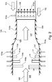
- Figure 3 shows a further dilution air mixer arrangement 200.
- compressed gas from the compressor plenum is guided along combustor liner in a connection duct 111 as air plenum, in which the dilution air flow 110 flows after the sequential liner cooling.
- the dilution air mixer arrangement 200 can be arranged with an annular cross section.
- the height H corresponds to the difference between the diameter of an outer wall of the annular flow section and the inner wall of the annular flow section.
- connection duct 111 From the mentioned connection duct 111 a first part of the flow air 110 is injected as dilution air 110a into the mixer arrangement via at least one injection pipe group 114 a-d having various lengths La-d. Additionally, a second part of the flow air 110 is injected as effusion air 110b into the mixer arrangement via various injection holes 125 disposed along the whole extension of the mixer arrangement 200, i.e. from the hot gas inlet 126 to the mixer outlet 127, precisely to a downstream arranged fuel injector 128.
- the height L a-d of the various subsequently disposed injection pipes 114 a-c are chosen such that good mixing of injected dilution air flow 110 with the hot gas 109 leaving the first combustion chamber is assured.
- the mixer arrangement 115 comprising at least one or more groups of injection pipes 114 a-d pointing inwards from the side walls of the mixer arrangement for admixing the dilution air 110a to cool the hot gases 109 leaving the first combustion chamber.
- the injection pipes 114 a-d are circumferentially distributed along the side wall of the mixer arrangement and wherein the injection pipes having a cylindrical, conical or quasi-conical shape addressed to the center of the mixer arrangement.
- the injection pipes of a first group have a first protrusion depth into the hot gas flow path 109
- the second injection pipes of the second group have a second protrusion depth
- the third injection pipes of the third group have a third protrusion
- the fourth injection pipes of the fourth group have a fourth protrusion depth.
- the mixer arrangement is arranged such that the dilution air is admixed during operation to cool the hot gases 109.
- the protrusion depth of the injection pipes of the first group compared to the last group may be regularly increasing or decreasing, whereby a mutual depth of the injection pipes along the respective group is also possible.
- the number of injection pipes can be chosen such that the distance between the exit-openings of neighboring injection pipes are similar. Similar in this context can mean that the distance between exit openings in the group with larger penetration depth one to three times the distance between exit openings of injection pipes of the group with smaller penetration depth.
- the distance between exit openings can further be increased with the exit diameter of the injection pipes. For example it can be proportional to the exit diameter.
- the mixer arrangement comprising in the hot gas flow direction at least one row of injection pipes with equal, similar or different protrusion depth, wherein the mixer comprising multiple rows of injection pipes in the hot gas flow direction with equal, similar or different protrusion depth.
- At least one injection pipe group is circumferentially distributed along the side wall of the mixer arrangement and having a staggered design relative to a plane normal to the main flow direction of the hot gases flowing through the mixer, wherein the stagger can be designed between 0.1 and 3.5 times the diameter of the relative injection pipes.
- the protrusion depth of the injection pipes of the first row is closer to the center of the mixer arrangement than the protrusion depth of a second row, then, the protrusion depth of the second row is closer or further to the center of the mixer than the protrusion depth of the third row, wherein the injection pipes of the single row extending approximately to the center of the mixer and are arranged in radial direction inversely to each other.
- the injection pipes can be comprised along their protrusion depth a number of injection holes used to inject orthogonally or quasi-orthogonally the flowed dilution air into the hot gas flow. Furthermore, the injection pipes having uniform or non-uniform conical gradient along the respective protrusion depth.
- the injection pipes can be inclined in the hot gas flow direction at an angle of less than 90° relative to the flow direction of the hot gases such that the dilution air leaving the pipes have a flow component in the direction of the hot gas flow at the location of the injection.
- dilution air 129 could be taken from the upstream compressor plenum with full Pk2 and a lower temperature Tk2.
- a first part 130a of this dilution air 129 is directed to at least one injection pipe group 114a but any other combination can be considered.
- a second part 130b of the mentioned dilution air 129 cools 130b' the fuel injector 128.
- Figure 4 shows a baseline of a preferred embodiment of the invention in which a series of injection pipes 224, 225 are mounted radially and fed by a further plenum with dilution air flow 220.
- the hot gas flow generated by the first combustor flows through the radially disposed long injection pipes 224, and intermediated disposed short injection pipes 225.
- Both, the long and the short injection pipes are directed radially towards the center of the mixer 222, wherein the long injection pipes 224 extending nearly to the center of the mentioned mixers.
- the disposition of the injection pipes 224, 225 in the circumferential direction of the mixer is uniformly provided, wherein a non-uniform distribution is also possible.
- Each injection pipes 224, 225 are also equipped with a large number of injection holes 223 used to inject the flowed dilution air 221 into the hot gas flow 109 (see Figure 4 ).
- the key feature of this mixer 222 reflects a good distribution of such injection holes 223 along the respective radial extension of the injection pipes 224, 225, so that the dilution air flow 220 is pre-distributed and therefore requiring a much shorter mixing time and length.
- the injection pipes characterized by conical or other geometries, are arranged to cover the full cross sectional area with dilution air being injected into the hot gas flow, orthogonal to the page.
- Figure 5 shows a baseline of a further preferred embodiment of the invention in which a series of injection pipes 224 are mounted radially and fed by a further plenum with dilution air flow 220.
- the hot gas flow generated by the first combustor flows through the radially disposed long injection pipes 224, which having uniformly length.
- the injection pipes 224 as shown, are directed radially towards the center of the mixer 222, and they extending nearly to the center of the mixer.
- the disposition of the injection pipes 224 in the circumferential direction of the mixer is uniformly provided, wherein a non-uniform distribution is also possible.
- Each injection pipes 224 are also equipped with a large number of injection holes 223 used to inject the flowed dilution air 221 into the hot gas flow 109 (see Figure 4 ).
- the key feature of this mixer 222 reflects a good distribution of such injection holes 223 along the respective radial extension of the injection pipes 224, so that the dilution air flow 220 is pre-distributed and therefore requiring a much shorter mixing time and length.
- the injection pipes characterized by conical or other geometries, are arranged to cover the full cross sectional area with dilution air being injected into the hot gas flow, orthogonal to the page. All injection pipes possess the same length.
Landscapes
- Engineering & Computer Science (AREA)
- Chemical & Material Sciences (AREA)
- Combustion & Propulsion (AREA)
- Mechanical Engineering (AREA)
- General Engineering & Computer Science (AREA)
Description
- The invention refers to a separate feedings of cooling air and dilution air (dilution medium) arrangement of a gas turbine engine or power plant, comprising at least one combustion chamber, at least one mixer for admixing a dilution air to the hot gas flow leaving the combustion chamber, wherein the mixer is adapted to guide combustion gases in a hot gas flow path extending downstream of the combustion chamber, wherein the mixer comprises a plurality of injection pipes pointing inwards from the side walls of the mixer for admixing the dilution medium or air to cool the hot gas flow leaving combustion chamber, according to the preamble of claim 1.
- Preferentially, the invention refers to a gas turbine engine comprising a single combustor or a sequential combustor arrangement. The sequential combustion arrangement comprising a first burner, a first combustion chamber, a mixer for admixing a dilution gas to the hot gases leaving the first combustion chamber during operation, a second combustion chamber arranged sequentially in a fluid flow connection.
- The mixer is adapted to guide combustion gases in a hot gas flow path extending between the first combustion chamber and the second burner comprising a duct having an inlet at an upstream end adapted for connection to the first combustion chamber and an outlet at a downstream end adapted for connection to the second combustion chamber.
- Additionally, the component of an operational arrangement concerns for example a can-combustor of a gas turbine engine. Moreover, an operational arrangement concerns also every other engine that may be subject to a combustion.
- As one example the invention refers to a gas turbine engine having a pattern of several can-combustors disposed around rotational contour.
- Can-combustors are self-contained cylindrical combustion chambers. Each "can-combustor" has its own fuel injector, igniter, liner, and casing. The primary air from the compressor is guided into each individual can-combustor, where it is decelerated, mixed with fuel, and then ignited. The secondary air also comes from the compressor, where it is fed outside of the liner (inside of which is where the combustion is taking place). The secondary air is then fed, usually through slits in the liner, into the combustion zone to cool the liner or liners, which are usually cooled by convective cooling, to avoid cooling air to enter into the hot gas after the flame.
- Furthermore, multiple can-combustors are arranged around the central axis of the engine, and their shared exhaust is fed to the turbine(s). Can-combustors were most widely used in early gas turbine engines, owing to their ease of design and testing (one can test a single can, rather than have to test the whole system). Can-combustors are easy to maintain, as only a single can needs to be removed, rather than the whole combustion section.
- The focused gas turbine engine comprising a compressor, downstream of the compressor several can-combustors, whereas the hot gases of the can-combustors are admitted to a turbine, whereas the can-combustors operating on the basis of can-combustor architecture.
- Additionally, another gas turbine engine comprising a compressor, downstream of the compressor first can-combustor arrangement, whereas the hot gases of the first can-combustor arrangement are admitted to a first turbine or to a second can-combustor arrangement, whereas the hot gases of the second can-combustor arrangement are admitted to a second turbine or to a subsequent steam cycle, whereas at least one can-combustor arrangement operating on the basis of a can-combustor architecture.
- Furthermore, at least one can-combustor comprising one or more disposed premixing burners or semi-premixing burners. A first turbine is connected to receive working gas from the first can-combustor arrangement, a second can-combustor arrangement is connected to receive exhausted working gas from the first turbine and to deliver working gas to the second turbine, wherein the second can-combustor arrangement comprises an annular duct forming a combustion space extending in a flow direction from outlet of the first turbine to an inlet of the second turbine, and means for introducing fuel into the second can-combustor arrangement for self-ignition combustion.
- Moreover, the operational use of the apparatus of the present invention also refers preferably to a further type of combustor, namely is the cannular combustor. Like the can-combustor, can annular combustors have discrete combustion zones contained in separate liners with their own fuel-injectors. Unlike the can-combustor, all the combustion zones share a common ring (annulus) casing.
- Each combustion zone no longer has to serve as a pressure vessel. The combustion zones can also "communicate" with each other via liner holes or connecting tubes or pipes that allow some air to flow circumferentially. The exit flow from the cannular combustor generally has a more uniform temperature profile, which is better for the turbine section. It also eliminates the need for each chamber to have its own igniter. Once the fire is lit in one or two can-combustors, it can easily spread to and ignite the others.
- The combustor of the gas turbine engine comprising at least one premix burner, these should preferably be formed by the combustion process and objects according to the documents
EP 0 321 809 A1 and/orEP 0 704 657 A2 , wherein these documents forming an integral part of the present description. In particular, said premix burners can be operated with liquid and/or gaseous fuels of all kinds. Thus, it is readily possible to provide different fuels within the individual cans. This means also that a premix burner can also be operated simultaneously with different fuels. - Due to increased power generation by unsteady renewable sources like wind or solar existing gas turbine based power plants are increasingly used to balance power demand and to stabilize the grid. Thus improved operational flexibility is required. This implies that gas turbines are often operated at lower load than the base load design point, i.e. at lower combustor inlet and firing temperatures.
- At the same time, emission limit values and overall emission permits are becoming more stringent, so that it is required to operate at lower emission values, keep low emissions also at part load operation and during transients, as these also count for cumulative emission limits.
- State-of-the-art combustion systems are designed to cope with a certain variability in operating conditions, e.g. by adjusting the compressor inlet mass flow or controlling the fuel split among different burners, fuel stages or combustors. However, this is not sufficient to meet the new requirements.
- To further reduce emissions and operational flexibility sequential combustion has been suggested in
DE 10312971 A1 . Depending on the operating conditions, in particular on the hot gas temperature of a first combustion chamber it can be necessary to cool the hot gases before they are admitted to a second burner (also called sequential burner). This cooling can be advantageous to allow fuel injection and premixing of the injected fuel with the hot flue gases of the first combustor in the second burner. - Conventional cooling methods either require heat exchanger structures which lead to high pressure drops in the main hog gas flow or suggest injection of a cooling medium from the side walls. For injection of a cooling medium from the side walls a high pressure drop is required which is detrimental to the efficiency of a gas turbine operated with such a combustor arrangement and a controlled cooling of the whole flow is difficult.
- With reference to
WO 2014/063835 A1 , which discloses the preamble of claim 1, a sequential combustor arrangement comprising a first burner, a first combustion chamber, a mixer or admixing a dilution gas to the hot gases leaving the first combustion chamber during operation, a second burner, and a second combustion chamber arranged sequentially in a fluid flow connection. The mixer is adapted to guide combustion gases in a hot gas flow path extending between the first combustion chamber and the second burner comprising a duct having an inlet at an upstream end adapted for connection to the first combustion chamber and an outlet at a downstream end adapted for connection to the second burner. The mixer comprises a plurality of injection pipes pointing inwards from the side walls of the mixer for admixing the dilution gas to cool the hot flue gases leaving the first combustion chamber.
In additionWO 2014/063835 A1 describes a method for operating a gas turbine with at least a compressor, a combustor arrangement comprising a first burner, a first combustion chamber, a mixer for admixing a dilution gas to the hot gases leaving the first combustion chamber during operation, a second burner and a second combustion chamber arranged sequentially in a fluid flow connection. The mixer is adapted to guide combustion gases in a hot gas flow path extending between the first combustion chamber and the second burner comprising a duct having an inlet at an upstream end adapted for connection to the first combustion chamber and an outlet at a downstream end adapted for connection to the second burner. The mixer comprises a plurality of injection pipes pointing inwards from the side walls of the duct for admixing the dilution gas to cool the hot flue gases leaving the first combustion chamber, and a turbine. The dilution gas is admixed into different regions of the cross section of the mixer or the dilution gas is injected through injection holes and/or second injection pipes and first injection pipes in order to introduce dilution gas into different regions of the cross section of the mixer. - Furthermore, attenuation of combustion dynamics by making use of Helmholtz dampers are widely used by all the companies operating in the gas turbine sector and several invention disclosures have been filed. The emerged state of the art focus on damper applications to can-annular-combustors. Adopting a Helmholtz damper around a can-combustor can be seen in the following documents:
US 2005/0166596 A1 describes a through-flow resonator, which when placed at or near the points having the highest acoustical pressure amplitudes within the flow path of a combustor system, effectively dampens instabilities from acoustic energy while avoiding an increase in mass air flow bypassing the system when a portion of the resonator is integral to a section of the system having a thickness in excess of about 0,24 cm (0.1 inch). The acoustic damping performance of a resonator may be expressed in terms of acoustic conductance, which is defined as the in-phase component of volume velocity through the downstream set of holes, divided by the amplitude of pressure oscillation at the downstream face of the resonator. A high value of acoustic conductance indicates high damping performance. Consequently, the higher the acoustic conductance of a resonator, the fewer individual resonators required within a system, such as a gas turbine, to minimize potentially damaging combustion oscillations, or the greater the likelihood against the occurrence of such combustion oscillations. -
US 2011/0220433 A1 provides the following solutions: A first aspect of the present object is a combustor including a cylindrical body that defines a combustion area therein, and an acoustic damper that includes an acoustic portion having an acoustic-damper resonance space communicating with the combustion area. The acoustic portion is provided along the cylindrical body so as to extend in a direction intersecting an axial direction of the cylindrical body. According to this aspect, because the acoustic portion having the acoustic-damper resonance space is provided along the cylindrical body so as to extend in the direction intersecting the axial direction of the cylindrical body, or the circumferential direction, the acoustic portion is disposed widely in the circumferential direction, without concentrating in a particular area of the cylindrical body in the circumferential direction. As a result, the acoustic portion is prevented from protruding toward the outer circumference of the cylindrical body, and the space needed outside the combustor can be reduced. Thus, because the casing can be made small, the housing constituting the casing can be made small. Because this enables, for example, the gas turbine to be adequately transported on the ground, it is possible to reduce the manufacturing costs, including the transportation costs. Furthermore, if the protrusion of the acoustic portion toward the outer circumference of the cylindrical body is reduced, the combustor can be easily extracted together with the acoustic damper. Thus, it is possible to improve the ease of maintenance of the combustor. The above-described aspect may further include an acoustic liner formed by a porous plate that constitutes the cylindrical body and has a plurality of through-holes penetrating in a thickness direction and a cover member that is provided around and at a certain distance from the porous plate so as to cover the porous plate, the acoustic liner having an acoustic-liner resonance space, By doing so, it is possible to attenuate oscillations in a frequency region that can be attenuated by the acoustic liner and oscillations in a frequency region that can be attenuated by the acoustic damper. Accordingly, it is possible to attenuate combustion oscillations in a wide frequency region. In the above configuration, it is preferable that at least part of the acoustic portion be provided on the outer circumferential side of the acoustic liner, - Accordingly, feeding directly from compressor plenum does not leave enough air for sequential liner cooling. Used air from sequential liner cooling increases risks of hot gas ingestion, overheating in regions with low pressure drop and coupling between hot gas and mixer air plenum. Another solution could be a major pressure drop increase over dilution air, but this releases detrimental effects on engine performance.
-
EP 2 725 300 A1 discloses a gas turbine, comprising a compressor, a compressor plenum and a combustor arrangement, the combustor arrangement comprising at least one combustion chamber, at least one mixer arrangement for admixing an air or gas portions to the hot gas flow leaving the combustion chamber, wherein the mixer arrangement is adapted to guide combustion gases in a hot gas flow path extending downstream of the combustion chamber, wherein the mixer comprises a mixer plenum, a fuel injector at the outlet of the mixer arrangement and a plurality of injection pipes pointing inwards from the side walls of the mixer arrangement for admixing air portions to cool at least the hot gas flow leaving combustion chamber, wherein the mixer arrangement receives at least one portion of dilution air flowing from the compressor plenum and at least one portion of cooling air flowing from the mixer plenum, wherein a first part of the cooling air is injected the Injection pipes and a second part of the cooling air is injected as effusion air into the mixer arrangement via injection holes disposed along the whole extension of the mixer arrangement. Other examples of known gas turbines are disclosed inUS 5 667 572 A , inEP 0 178 820 A1 , inJP D59 13829 A GB 579 424 A - According to the present invention, there is provided a gas turbine as defined In claim 1.
- In order to introduce an innovative and inventive contribution to the mentioned state of the art, the basic idea of the invention is to feed only part of the dilution air and of the cooling air from the compressor plenum and the rest from the sequential liner exit. This inventive contribution can solve cooling problems, minimize hot gas ingestion risks, minimize self-ignition risks in the sequential burner injection unit and reduce pulsation issues.
- Additionally, the technical problem which the invention intends to solve, consists in the fact that a large amount of the air used in CPSC (constant pressure sequential combustion) systems needs to be injected after the first combustion stage. Currently two options were considered:
- a) Air fed from the compressor plenum making the cooling of the sequential liner extremely challenging.
- b) Air from the sequential liner (used for SL cooling) posing mixer issues, risks of strong coupling between mixer plenum and hot gas with pulsation, risks of self-ignition in the injection unit and risks of hot gas injection in the mixer.
- The typical configuration of an internal CPSC system consists in the fact, that the hot gas coming from the first combustion stage is cooled down to the optimum sequential-burner inlet temperature by injection of dilution air and cooling air, the latter also ensuring that metal temperature limits of the various parts are not exceeded. All the air is fed from the same plenum, in this case a plenum downstream of the SL, whose pressure is lower than Pk2 (Compressor) and whose temperature is higher than Tk2 (Compressor) due to having already used such air for SL cooling.
- The idea of taking air from different plena is a basic idea of this invention. Some of the dilution air could be taken from the upstream compressor plenum with full Pk2 and a lower temperature (Tk2).
- The example of feeding the first mixer row is sketched in the invention basic figure under "Detailed description of exemplary embodiments" but any other combination can be considered. This has these key advantages:
- c) Reduced thermo-acoustic coupling between hot gas path and mixer plenum;
- d) More effective cooling of the mixer;
- e) Lower risk of hot gas ingestion;
- f) Higher penetration of dilution air (-->better mixing, NOx, CO, margin against overheating).
- In the same figure it is also shown the idea of feeding the injection unit cooling air flowing from a plenum with higher pressure and lower temperature. This has the important advantages of lowering the risks of self-ignition of fuel recirculating in the fuel injector cooling air and providing a more effective cooling of the injection unit.
- Further advantages of the invention are as follows:
Lower risks of: - Hot gas ingestion;
- self-ignition in the injection unit;
- thermo-acoustic coupling between hot gas and mixer plenum;
- Thus, better mixing of hot gas and dilution air (more margin against sequential burner overheating, lower NOx and CO)
- Accordingly, the invention refers to a combustor arrangement of a gas turbine engine or power plant, comprising at least one combustion chamber, at least one mixer arrangement for admixing air or gas to the hot gas flow leaving the combustion chamber. The mixer arrangement is adapted to guide combustion gases in a hot gas flow path extending downstream of the combustion chamber, wherein the mixer comprises a plurality of injection pipes pointing inwards from the side walls of the mixer arrangement for admixing air portions to cool at least the hot gas flow leaving combustion chamber. The mixer arrangement is applied to at least one volume of dilution air flowing from a first plenum and at least one volume of cooling air flowing from a second plenum.
- The dilution air flowing from the first plenum charges directly or indirectly at least one injection pipe, whereby the dilution air is originated flowing from the compressor of the gas turbine engine or power plant.
- The cooling air flowing from the second plenum is used as effusion cooling air with respect to the inner liner of the hot gas flow.
- The cooling air flowing from the second plenum charges directly or indirectly at least one injection pipe, and the cooling air is originated from the precedent cooling of the sequential liner, and that the cooling air flows along a connecting duct, which is disposed annularly around the hot gas flow.
- A fuel injector is arranged at the outlet of the mixer arrangement, whereby the fuel injector is cooled by a quantity of dilution air flowing from the first plenum.
- Injection pipes pointing inward from the inner liner of the hot gas flow, and are arranged with a regular or irregular partitioning in circumferential direction of the hot gas flow, whereby the injection pipes having a cylindrical, conical or quasi-conical shape. Additionally, the mixer arrangement comprising multiple injection pipe rows along the hot gas flow with equal, similar, different protrusion depth. Furthermore, the injection pipes of the mixer arrangement having an equal, similar, different cross-section.
- The injection pipes of a single row extending to the center of the mixer and are arranged in radial direction inversely to each other. Alternatively, at least one injection pipe is inclined with respect to the hot gas flow.
- A preferred alternative includes the embodiment that at least one injection pipe having along their protrusion depth a number of injection holes using to inject orthogonally or quasi-orthogonally flowed dilution air into the hot gas flow.
- Furthermore, the invention refers to a method for operating a combustor arrangement of a gas turbine engine or power plant, comprising at least one combustion chamber, at least one mixer arrangement for admixing air or gas to the hot gas flow leaving the combustion chamber. Mixer arrangement is adapted to guide combustion gases in a hot gas flow path extending downstream of the combustion chamber, wherein the mixer comprises a plurality of injection pipes pointing inwards from the side walls of the mixer arrangement for admixing air portions to cool at least the hot gas flow leaving combustion chamber. The mixer arrangement is applied to at least one volume of dilution air flowing from a first plenum and at least one volume of cooling air flowing from a second plenum.
- Moreover, the proposed mixer arrangement can be operated as a damper, reducing thermo-acoustic coupling between hot gas path and mixer plenum.
- The disclosure, its nature as well as its advantages, shall be described in more detail below with the aid of the accompanying figures. Referring to the figures:
- Figure 1
- shows a generic gas turbine engine using sequential combustion with a mixer arrangement for admixing dilution air or a dilution gas;
- Figure 2
- shows a mixer arrangement of a gas turbine engine comprising an introduction of a cooling air and dilution air according to the prior art;
- Figure 3
- shows a mixer arrangement of a gas turbine engine comprising an introduction of a cooling air and dilution air coming from two different plena according to the invention;
- Figure 4
- shows a cross section of a mixer comprising a series of injection pipes mounted circumferentially and extending in radial direction;
- Figure 5
- shows further cross section of a mixer.
-
Figure 1 shows generalized agas turbine engine 100 with asequential combustor arrangement 104 according to the disclosure. It comprises acompressor 103, acombustor arrangement 104, and aturbine 105. Thecombustor arrangement 104 comprises afirst burner 112, afirst combustion chamber 101, and amixer arrangement 115 for admixing a dilution air to thehot gases 109 leaving thefirst combustion chamber 101 during operation. Downstream of themixer arrangement 115 thecombustor arrangement 104 additionally comprises asecond burner 113, and asecond combustion chamber 102. Thefirst burner 112,first combustion chamber 101,mixer 115,second burner 113 andsecond combustion chamber 102 are arranged sequentially in a fluid flow connection. Fuel can be introduced into thefirst burner 112 via afirst fuel injection 123, mixed with compressed air which is compressed in thecompressor 103, and combusted in thefirst combustion chamber 101. Dilution air is admixed in thesubsequent mixer arrangement 115. Additional fuel can be introduced into the second burner via asecond fuel injection 124, mixed withhot gases 109 leaving themixer arrangement 115, and combusted in thesecond combustion chamber 102. Thehot gases 109 leaving thesecond combustion chamber 102 are expanded in thesubsequent turbine 105, performing work. Theturbine 105 andcompressor 103 are arranged on ashaft 106. The remaining heat of theexhaust gas 107 leaving theturbine 105 can be further used in a heat recovery steam generator or boiler (not shown) for steam generation. In the example shown here compressor exit gas is admixed as dilution air. Typically, compressor exit gas is compressedambient air 108. For gas turbines with flue gas recirculation (not shown) the compressor exit gas is a mixture of ambient air and recirculated flue gas. Typically, the gas turbine system includes a generator (not shown) which is coupled to ashaft 106 of thegas turbine 100. -
Figure 2 shows a dilutionair mixer arrangement 115 according to the state of the art. In this example compressed gas from the compressor plenum is guided along combustor liner in a connection duct (not shown, but seeWO 2014/063835 ) as air plenum of thedilution air flow 110. From the mentioned connection duct a first part of thedilution air flow 110 is injected asdilution air 110a into the mixer via injection pipes 114 a-d having various lengths La-d. Additionally, a second part of theflow air 110 is injected aseffusion air 110b into the mixer via injection holes 125 disposed along the whole extension of themixer arrangement 115, i.e. from thehot gas inlet 126 to themixer outlet 127, precisely to a downstream arranged and cooled 110c'fuel injector 128. - The height L a-d of the various subsequently disposed injection pipes 114 a-c are chosen such that good mixing of injected
dilution air flow 110 with thehot gas 109 leaving the first combustion chamber is assured. - Furthermore, the
mixer arrangement 115 comprising at least one or more groups of injection pipes 114 a-d pointing inwards from the side walls of the mixer arrangement for admixing thedilution air 110a to cool thehot gases 109 leaving the first combustion chamber. The injection pipes 114 a-d are circumferentially distributed along the side wall of the mixer arrangement and wherein the injection pipes having a cylindrical, conical or quasi-conical shape addressed to the center of the mixer arrangement. - For example, the injection pipes of a first group have a first protrusion depth into the hot
gas flow path 109, the second injection pipes of the second group have a second protrusion depth, the third injection pipes of the third group have a third protrusion, and the fourth injection pipes of the fourth group have a fourth protrusion depth. The mixer arrangement is arranged such that the dilution air is admixed during operation to cool thehot gases 109. - Moreover, the protrusion depth of the injection pipes of the first group compared to the last group may be regularly increasing or decreasing, whereby a mutual depth of the injection pipes along the respective group is also possible.
- Additionally, the number of injection pipes can be chosen such that the distance between the exit-openings of neighboring injection pipes are similar. Similar in this context can mean that the distance between exit openings in the group with larger penetration depth one to three times the distance between exit openings of injection pipes of the group with smaller penetration depth. The distance between exit openings can further be increased with the exit diameter of the injection pipes. For example it can be proportional to the exit diameter.
- Moreover, the mixer arrangement comprising in the hot gas flow direction at least one row of injection pipes with equal, similar or different protrusion depth, wherein the mixer comprising multiple rows of injection pipes in the hot gas flow direction with equal, similar or different protrusion depth.
- At least one injection pipe group is circumferentially distributed along the side wall of the mixer arrangement and having a staggered design relative to a plane normal to the main flow direction of the hot gases flowing through the mixer, wherein the stagger can be designed between 0.1 and 3.5 times the diameter of the relative injection pipes.
- The protrusion depth of the injection pipes of the first row is closer to the center of the mixer arrangement than the protrusion depth of a second row, then, the protrusion depth of the second row is closer or further to the center of the mixer than the protrusion depth of the third row, wherein the injection pipes of the single row extending approximately to the center of the mixer and are arranged in radial direction inversely to each other.
- The injection pipes can be comprised along their protrusion depth a number of injection holes used to inject orthogonally or quasi-orthogonally the flowed dilution air into the hot gas flow. Furthermore, the injection pipes having uniform or non-uniform conical gradient along the respective protrusion depth.
- Moreover, the injection pipes can be inclined in the hot gas flow direction at an angle of less than 90° relative to the flow direction of the hot gases such that the dilution air leaving the pipes have a flow component in the direction of the hot gas flow at the location of the injection.
-
Figure 3 shows a further dilutionair mixer arrangement 200. In this example compressed gas from the compressor plenum is guided along combustor liner in aconnection duct 111 as air plenum, in which thedilution air flow 110 flows after the sequential liner cooling. The dilutionair mixer arrangement 200 can be arranged with an annular cross section. For an annular dilution air mixer arrangement the height H corresponds to the difference between the diameter of an outer wall of the annular flow section and the inner wall of the annular flow section. - From the mentioned connection duct 111 a first part of the
flow air 110 is injected asdilution air 110a into the mixer arrangement via at least one injection pipe group 114 a-d having various lengths La-d. Additionally, a second part of theflow air 110 is injected aseffusion air 110b into the mixer arrangement viavarious injection holes 125 disposed along the whole extension of themixer arrangement 200, i.e. from thehot gas inlet 126 to themixer outlet 127, precisely to a downstream arrangedfuel injector 128. - The height L a-d of the various subsequently disposed injection pipes 114 a-c are chosen such that good mixing of injected
dilution air flow 110 with thehot gas 109 leaving the first combustion chamber is assured. - Furthermore, the
mixer arrangement 115 comprising at least one or more groups of injection pipes 114 a-d pointing inwards from the side walls of the mixer arrangement for admixing thedilution air 110a to cool thehot gases 109 leaving the first combustion chamber. The injection pipes 114 a-d are circumferentially distributed along the side wall of the mixer arrangement and wherein the injection pipes having a cylindrical, conical or quasi-conical shape addressed to the center of the mixer arrangement. - For example, the injection pipes of a first group have a first protrusion depth into the hot
gas flow path 109, the second injection pipes of the second group have a second protrusion depth, the third injection pipes of the third group have a third protrusion, and the fourth injection pipes of the fourth group have a fourth protrusion depth. The mixer arrangement is arranged such that the dilution air is admixed during operation to cool thehot gases 109. - Moreover, the protrusion depth of the injection pipes of the first group compared to the last group may be regularly increasing or decreasing, whereby a mutual depth of the injection pipes along the respective group is also possible.
- Additionally, the number of injection pipes can be chosen such that the distance between the exit-openings of neighboring injection pipes are similar. Similar in this context can mean that the distance between exit openings in the group with larger penetration depth one to three times the distance between exit openings of injection pipes of the group with smaller penetration depth. The distance between exit openings can further be increased with the exit diameter of the injection pipes. For example it can be proportional to the exit diameter.
- Moreover, the mixer arrangement comprising in the hot gas flow direction at least one row of injection pipes with equal, similar or different protrusion depth, wherein the mixer comprising multiple rows of injection pipes in the hot gas flow direction with equal, similar or different protrusion depth.
- At least one injection pipe group is circumferentially distributed along the side wall of the mixer arrangement and having a staggered design relative to a plane normal to the main flow direction of the hot gases flowing through the mixer, wherein the stagger can be designed between 0.1 and 3.5 times the diameter of the relative injection pipes.
- The protrusion depth of the injection pipes of the first row is closer to the center of the mixer arrangement than the protrusion depth of a second row, then, the protrusion depth of the second row is closer or further to the center of the mixer than the protrusion depth of the third row, wherein the injection pipes of the single row extending approximately to the center of the mixer and are arranged in radial direction inversely to each other.
- The injection pipes can be comprised along their protrusion depth a number of injection holes used to inject orthogonally or quasi-orthogonally the flowed dilution air into the hot gas flow. Furthermore, the injection pipes having uniform or non-uniform conical gradient along the respective protrusion depth.
- Moreover, the injection pipes can be inclined in the hot gas flow direction at an angle of less than 90° relative to the flow direction of the hot gases such that the dilution air leaving the pipes have a flow component in the direction of the hot gas flow at the location of the injection.
- Some of the
dilution air 129 could be taken from the upstream compressor plenum with full Pk2 and a lower temperature Tk2. Afirst part 130a of thisdilution air 129 is directed to at least oneinjection pipe group 114a but any other combination can be considered. Asecond part 130b of the mentioneddilution air 129 cools 130b' thefuel injector 128. -
Figure 4 shows a baseline of a preferred embodiment of the invention in which a series ofinjection pipes dilution air flow 220. In the Figure the hot gas flow generated by the first combustor flows through the radially disposedlong injection pipes 224, and intermediated disposedshort injection pipes 225. Both, the long and the short injection pipes are directed radially towards the center of themixer 222, wherein thelong injection pipes 224 extending nearly to the center of the mentioned mixers. The disposition of theinjection pipes injection pipes dilution air 221 into the hot gas flow 109 (seeFigure 4 ). The key feature of thismixer 222 reflects a good distribution of such injection holes 223 along the respective radial extension of theinjection pipes dilution air flow 220 is pre-distributed and therefore requiring a much shorter mixing time and length. In summary, the injection pipes, characterized by conical or other geometries, are arranged to cover the full cross sectional area with dilution air being injected into the hot gas flow, orthogonal to the page. -
Figure 5 shows a baseline of a further preferred embodiment of the invention in which a series ofinjection pipes 224 are mounted radially and fed by a further plenum withdilution air flow 220. In the Figure the hot gas flow generated by the first combustor flows through the radially disposedlong injection pipes 224, which having uniformly length. Accordingly, theinjection pipes 224, as shown, are directed radially towards the center of themixer 222, and they extending nearly to the center of the mixer. The disposition of theinjection pipes 224 in the circumferential direction of the mixer is uniformly provided, wherein a non-uniform distribution is also possible. Eachinjection pipes 224, are also equipped with a large number of injection holes 223 used to inject the floweddilution air 221 into the hot gas flow 109 (seeFigure 4 ). The key feature of thismixer 222 reflects a good distribution of such injection holes 223 along the respective radial extension of theinjection pipes 224, so that thedilution air flow 220 is pre-distributed and therefore requiring a much shorter mixing time and length. In summary, the injection pipes, characterized by conical or other geometries, are arranged to cover the full cross sectional area with dilution air being injected into the hot gas flow, orthogonal to the page. All injection pipes possess the same length. -
- 100
- Gas Turbine
- 101
- First combustor chamber
- 102
- Second combustor chamber
- 103
- Compressor
- 104
- Combustor arrangement
- 105
- Turbine
- 106
- Shaft
- 107
- Exhaust Gas
- 108
- Compressed Air
- 109
- Hot gas flow, path
- 110
- Dilution air flowing from a second plenum
- 110a
- Dilution air through the pipe
- 110b
- Dilution air through the effusion hole
- 110c
- Dilution air through the fuel injector
- 110c'
- Dilution air from the fuel injector
- 111
- Connecting duct
- 112
- First burner
- 113
- Second burner
- 114a
- Injection pipe
- 114b
- Injection pipe
- 114c
- Injection pipe
- 114d
- Injection pipe
- 115
- Mixer arrangement
- 126
- Hot gas inlet
- 127
- Mixer outlet
- 128
- Fuel injector
- 129
- Dilution air flowing from a first plenum
- 130a
- First portion
- 130b
- Second portion
- 130b'
- Cooling procedure of the fuel injector
- 200
- Mixer arrangement
- 220
- Dilution airflow
- 221
- Dilution air into the hot gas flow
- 222
- Mixer arrangement
- 223
- Injection hole
- 224
- Injection pipe
- 225
- Injection pipe
- L a-d
- Height of the various injection pipes
- H
- Height of the annular dilution air plenum
Claims (10)
- A gas turbine engine, comprising a compressor, a compressor plenum, a combustor arrangement and a turbine, the combustor arrangement comprising at least one combustion chamber, a connection duct (111) forming an air plenum, at least one mixer arrangement for admixing an air or gas portions to the hot gas flow leaving the combustion chamber, wherein the mixer arrangement is adapted to guide combustion gases in a hot gas flow path extending downstream of the combustion chamber, wherein the mixer comprises a fuel injector (128) at the outlet of the mixer arrangement and a plurality of injection pipes (114) pointing inwards from the side walls of the mixer arrangement for admixing air portions to cool at least the hot gas flow leaving combustion chamber, wherein the mixer arrangement (200, 222) receives at least one portion of dilution air (129) flowing from the compressor plenum and at least one portion of cooling air (110) flowing from the air plenum, wherein a first part (110a) of said cooling air (110) is injected via the injection pipes (114 b-d) and a second part (119b) of said cooling air (110) is injected as effusion air into the mixer arrangement via injection holes (125) disposed along the whole extension of the mixer arrangement, wherein the injection pipes (114) include an injection pipe group (114a), wherein a first portion (130a) of the dilution air (129) from the compressor plenum is supplied in the hot gas flow path through the injection pipe group (114a), characterized in that, a second portion (130b) of the dilution air (129) is supplied through the fuel injector (128), whereby the fuel injector (128) is cooled by the second portion (130b) of the dilution air (129).
- The combustor arrangement according to claim 1, characterized in that the cooling air (110) flowing from the air plenum flows along the connecting duct (111), which is disposed annularly around the hot gas flow (109).
- The combustor arrangement according to one of the claims 1 or 2, characterized in that the injection pipes (114 a-d) pointing inward from the inner liner of the hot gas flow, and are arranged with a regular or irregular partitioning in circumferential direction of the hot gas flow.
- The combustor arrangement according to one of the claims 1 to 3, characterized in that the injection pipes (114 a-d) having a cylindrical, conical or quasi-conical shape.
- The combustor arrangement according to one of the claims 1 to 4, characterized in that the mixer arrangement (200, 222) comprising multiple injection pipe rows along the hot gas flow with equal, similar, different protrusion depth.
- The combustor arrangement according to one of the claims 1 to 5, characterized in that the injection pipes of the mixer (200, 222) having an equal, similar, different cross-section.
- The combustor arrangement according to one of the claims 1 to 6, characterized in that the injection pipes of a single row extending to the center of the mixer and are arranged in radial direction inversely to each other.
- The combustor arrangement according to one of the claims 1 to 7, characterized in that at least one injection pipe is inclined with respect to the hot gas flow.
- The combustor arrangement according to one of the claims 1 to 8, characterized in that at least one injection pipe having along their protrusion depth a number of injection holes using to inject orthogonally or quasi-orthogonally flowed dilution air into the hot gas flow.
- Use of the mixer according to one of the claims 1 to 9 for operating as a damper.
Priority Applications (3)
| Application Number | Priority Date | Filing Date | Title |
|---|---|---|---|
| EP14199766.8A EP3037726B1 (en) | 2014-12-22 | 2014-12-22 | Separate feedings of cooling and dilution air |
| US14/973,367 US10443849B2 (en) | 2014-12-22 | 2015-12-17 | Separate feedings of cooling and dilution air |
| CN201510966598.4A CN105715378B (en) | 2014-12-22 | 2015-12-22 | Separate supply of cooling and dilution air |
Applications Claiming Priority (1)
| Application Number | Priority Date | Filing Date | Title |
|---|---|---|---|
| EP14199766.8A EP3037726B1 (en) | 2014-12-22 | 2014-12-22 | Separate feedings of cooling and dilution air |
Publications (2)
| Publication Number | Publication Date |
|---|---|
| EP3037726A1 EP3037726A1 (en) | 2016-06-29 |
| EP3037726B1 true EP3037726B1 (en) | 2018-09-26 |
Family
ID=52146292
Family Applications (1)
| Application Number | Title | Priority Date | Filing Date |
|---|---|---|---|
| EP14199766.8A Active EP3037726B1 (en) | 2014-12-22 | 2014-12-22 | Separate feedings of cooling and dilution air |
Country Status (3)
| Country | Link |
|---|---|
| US (1) | US10443849B2 (en) |
| EP (1) | EP3037726B1 (en) |
| CN (1) | CN105715378B (en) |
Cited By (1)
| Publication number | Priority date | Publication date | Assignee | Title |
|---|---|---|---|---|
| CN108534137A (en) * | 2017-03-02 | 2018-09-14 | 安萨尔多能源瑞士股份公司 | Mixer |
Families Citing this family (9)
| Publication number | Priority date | Publication date | Assignee | Title |
|---|---|---|---|---|
| CN104541104A (en) * | 2012-08-24 | 2015-04-22 | 阿尔斯通技术有限公司 | Sequential combustion with dilution gas mixer |
| EP3376003B1 (en) * | 2017-03-14 | 2020-04-29 | General Electric Company | Method and system for controlling a sequential gas turbine engine |
| US11092085B2 (en) | 2017-03-14 | 2021-08-17 | General Electric Company | Method and system for controlling a sequential gas turbine engine |
| EP3418638B1 (en) * | 2017-06-21 | 2021-03-24 | General Electric Company | Combustor with heat exchanger |
| CN109647235A (en) * | 2018-12-29 | 2019-04-19 | 苏州天蓝分析仪器有限公司 | A kind of dilution device based on gas mixing dilution mode |
| US11156164B2 (en) | 2019-05-21 | 2021-10-26 | General Electric Company | System and method for high frequency accoustic dampers with caps |
| US11174792B2 (en) | 2019-05-21 | 2021-11-16 | General Electric Company | System and method for high frequency acoustic dampers with baffles |
| CN111059531A (en) * | 2019-11-29 | 2020-04-24 | 北京森麟技术有限公司 | New Nitrogen Oxygen Burner |
| CN116792778A (en) * | 2022-03-21 | 2023-09-22 | 通用电气公司 | Turbine engine combustor and combustor liner |
Family Cites Families (19)
| Publication number | Priority date | Publication date | Assignee | Title |
|---|---|---|---|---|
| GB579424A (en) * | 1943-09-29 | 1946-08-02 | Lucas Ltd Joseph | Improvements relating to liquid fuel combustion apparatus for generating gases for power purposes |
| JPS5129726A (en) * | 1974-09-06 | 1976-03-13 | Mitsubishi Heavy Ind Ltd | |
| JPS5913829A (en) * | 1982-07-15 | 1984-01-24 | Hitachi Ltd | gas turbine combustor |
| CN85107191A (en) * | 1984-10-04 | 1986-09-24 | 西屋电气公司 | Impact type cooling gas turbine firing chamber with interior air film cooling |
| CH674561A5 (en) | 1987-12-21 | 1990-06-15 | Bbc Brown Boveri & Cie | |
| US5687572A (en) * | 1992-11-02 | 1997-11-18 | Alliedsignal Inc. | Thin wall combustor with backside impingement cooling |
| DE4435266A1 (en) | 1994-10-01 | 1996-04-04 | Abb Management Ag | burner |
| US6047550A (en) * | 1996-05-02 | 2000-04-11 | General Electric Co. | Premixing dry low NOx emissions combustor with lean direct injection of gas fuel |
| US6530221B1 (en) | 2000-09-21 | 2003-03-11 | Siemens Westinghouse Power Corporation | Modular resonators for suppressing combustion instabilities in gas turbine power plants |
| DE10312971B4 (en) | 2003-03-24 | 2017-04-06 | General Electric Technology Gmbh | Method for operating a gas turbine group |
| US7665309B2 (en) * | 2007-09-14 | 2010-02-23 | Siemens Energy, Inc. | Secondary fuel delivery system |
| US8161752B2 (en) * | 2008-11-20 | 2012-04-24 | Honeywell International Inc. | Combustors with inserts between dual wall liners |
| US8112216B2 (en) * | 2009-01-07 | 2012-02-07 | General Electric Company | Late lean injection with adjustable air splits |
| US8490744B2 (en) | 2009-02-27 | 2013-07-23 | Mitsubishi Heavy Industries, Ltd. | Combustor and gas turbine having the same |
| CH704829A2 (en) | 2011-04-08 | 2012-11-15 | Alstom Technology Ltd | Gas turbine group and associated operating method. |
| US9062884B2 (en) * | 2011-05-26 | 2015-06-23 | Honeywell International Inc. | Combustors with quench inserts |
| US9175604B2 (en) | 2011-09-08 | 2015-11-03 | Siemens Energy, Inc. | Gas turbine engine with high and intermediate temperature compressed air zones |
| CA2829613C (en) | 2012-10-22 | 2016-02-23 | Alstom Technology Ltd. | Method for operating a gas turbine with sequential combustion and gas turbine for conducting said method |
| EP2912381B1 (en) | 2012-10-24 | 2018-06-13 | Ansaldo Energia Switzerland AG | Sequential combustion with dilution gas mixer |
-
2014
- 2014-12-22 EP EP14199766.8A patent/EP3037726B1/en active Active
-
2015
- 2015-12-17 US US14/973,367 patent/US10443849B2/en active Active
- 2015-12-22 CN CN201510966598.4A patent/CN105715378B/en active Active
Non-Patent Citations (1)
| Title |
|---|
| None * |
Cited By (2)
| Publication number | Priority date | Publication date | Assignee | Title |
|---|---|---|---|---|
| CN108534137A (en) * | 2017-03-02 | 2018-09-14 | 安萨尔多能源瑞士股份公司 | Mixer |
| CN108534137B (en) * | 2017-03-02 | 2021-09-24 | 安萨尔多能源瑞士股份公司 | Mixing device |
Also Published As
| Publication number | Publication date |
|---|---|
| EP3037726A1 (en) | 2016-06-29 |
| US20160178200A1 (en) | 2016-06-23 |
| CN105715378B (en) | 2021-06-04 |
| US10443849B2 (en) | 2019-10-15 |
| CN105715378A (en) | 2016-06-29 |
Similar Documents
| Publication | Publication Date | Title |
|---|---|---|
| EP3037726B1 (en) | Separate feedings of cooling and dilution air | |
| EP3037728B1 (en) | Axially staged mixer with dilution air injection | |
| US10502423B2 (en) | Sequential combustion with dilution gas | |
| US10451283B2 (en) | Sequential combustor arrangement with a mixer | |
| EP2685172A2 (en) | Can-annular gas turbine combustion system with staged premix-combustion | |
| US10215417B2 (en) | Sequential combustor arrangement with a mixer | |
| EP2993404B1 (en) | Dilution gas or air mixer for a combustor of a gas turbine | |
| US20170184310A1 (en) | System for Injecting a Liquid Fuel into a Combustion Gas Flow Field | |
| US10323574B2 (en) | Mixer for admixing a dilution air to the hot gas flow | |
| AU2017296362B2 (en) | A swirl mesh lean direct injection concept for distributed flame holding for low pollutant emissions and mitigation of combustion instability | |
| WO2014173578A1 (en) | Sequential combustion with dilution gas | |
| EP2989389B1 (en) | Sequential combustion with dilution gas |
Legal Events
| Date | Code | Title | Description |
|---|---|---|---|
| PUAI | Public reference made under article 153(3) epc to a published international application that has entered the european phase |
Free format text: ORIGINAL CODE: 0009012 |
|
| AK | Designated contracting states |
Kind code of ref document: A1 Designated state(s): AL AT BE BG CH CY CZ DE DK EE ES FI FR GB GR HR HU IE IS IT LI LT LU LV MC MK MT NL NO PL PT RO RS SE SI SK SM TR |
|
| AX | Request for extension of the european patent |
Extension state: BA ME |
|
| RAP1 | Party data changed (applicant data changed or rights of an application transferred) |
Owner name: GENERAL ELECTRIC TECHNOLOGY GMBH |
|
| 17P | Request for examination filed |
Effective date: 20161229 |
|
| RBV | Designated contracting states (corrected) |
Designated state(s): AL AT BE BG CH CY CZ DE DK EE ES FI FR GB GR HR HU IE IS IT LI LT LU LV MC MK MT NL NO PL PT RO RS SE SI SK SM TR |
|
| RAP1 | Party data changed (applicant data changed or rights of an application transferred) |
Owner name: ANSALDO ENERGIA SWITZERLAND AG |
|
| 17Q | First examination report despatched |
Effective date: 20170906 |
|
| GRAP | Despatch of communication of intention to grant a patent |
Free format text: ORIGINAL CODE: EPIDOSNIGR1 |
|
| INTG | Intention to grant announced |
Effective date: 20180416 |
|
| GRAS | Grant fee paid |
Free format text: ORIGINAL CODE: EPIDOSNIGR3 |
|
| GRAA | (expected) grant |
Free format text: ORIGINAL CODE: 0009210 |
|
| AK | Designated contracting states |
Kind code of ref document: B1 Designated state(s): AL AT BE BG CH CY CZ DE DK EE ES FI FR GB GR HR HU IE IS IT LI LT LU LV MC MK MT NL NO PL PT RO RS SE SI SK SM TR |
|
| REG | Reference to a national code |
Ref country code: GB Ref legal event code: FG4D |
|
| REG | Reference to a national code |
Ref country code: CH Ref legal event code: EP |
|
| REG | Reference to a national code |
Ref country code: AT Ref legal event code: REF Ref document number: 1046462 Country of ref document: AT Kind code of ref document: T Effective date: 20181015 |
|
| REG | Reference to a national code |
Ref country code: IE Ref legal event code: FG4D |
|
| REG | Reference to a national code |
Ref country code: DE Ref legal event code: R096 Ref document number: 602014032943 Country of ref document: DE |
|
| REG | Reference to a national code |
Ref country code: NL Ref legal event code: MP Effective date: 20180926 |
|
| PG25 | Lapsed in a contracting state [announced via postgrant information from national office to epo] |
Ref country code: FI Free format text: LAPSE BECAUSE OF FAILURE TO SUBMIT A TRANSLATION OF THE DESCRIPTION OR TO PAY THE FEE WITHIN THE PRESCRIBED TIME-LIMIT Effective date: 20180926 Ref country code: LT Free format text: LAPSE BECAUSE OF FAILURE TO SUBMIT A TRANSLATION OF THE DESCRIPTION OR TO PAY THE FEE WITHIN THE PRESCRIBED TIME-LIMIT Effective date: 20180926 Ref country code: RS Free format text: LAPSE BECAUSE OF FAILURE TO SUBMIT A TRANSLATION OF THE DESCRIPTION OR TO PAY THE FEE WITHIN THE PRESCRIBED TIME-LIMIT Effective date: 20180926 Ref country code: BG Free format text: LAPSE BECAUSE OF FAILURE TO SUBMIT A TRANSLATION OF THE DESCRIPTION OR TO PAY THE FEE WITHIN THE PRESCRIBED TIME-LIMIT Effective date: 20181226 Ref country code: NO Free format text: LAPSE BECAUSE OF FAILURE TO SUBMIT A TRANSLATION OF THE DESCRIPTION OR TO PAY THE FEE WITHIN THE PRESCRIBED TIME-LIMIT Effective date: 20181226 Ref country code: GR Free format text: LAPSE BECAUSE OF FAILURE TO SUBMIT A TRANSLATION OF THE DESCRIPTION OR TO PAY THE FEE WITHIN THE PRESCRIBED TIME-LIMIT Effective date: 20181227 Ref country code: SE Free format text: LAPSE BECAUSE OF FAILURE TO SUBMIT A TRANSLATION OF THE DESCRIPTION OR TO PAY THE FEE WITHIN THE PRESCRIBED TIME-LIMIT Effective date: 20180926 |
|
| REG | Reference to a national code |
Ref country code: LT Ref legal event code: MG4D |
|
| PG25 | Lapsed in a contracting state [announced via postgrant information from national office to epo] |
Ref country code: AL Free format text: LAPSE BECAUSE OF FAILURE TO SUBMIT A TRANSLATION OF THE DESCRIPTION OR TO PAY THE FEE WITHIN THE PRESCRIBED TIME-LIMIT Effective date: 20180926 Ref country code: LV Free format text: LAPSE BECAUSE OF FAILURE TO SUBMIT A TRANSLATION OF THE DESCRIPTION OR TO PAY THE FEE WITHIN THE PRESCRIBED TIME-LIMIT Effective date: 20180926 Ref country code: HR Free format text: LAPSE BECAUSE OF FAILURE TO SUBMIT A TRANSLATION OF THE DESCRIPTION OR TO PAY THE FEE WITHIN THE PRESCRIBED TIME-LIMIT Effective date: 20180926 |
|
| REG | Reference to a national code |
Ref country code: AT Ref legal event code: MK05 Ref document number: 1046462 Country of ref document: AT Kind code of ref document: T Effective date: 20180926 |
|
| PG25 | Lapsed in a contracting state [announced via postgrant information from national office to epo] |
Ref country code: IT Free format text: LAPSE BECAUSE OF FAILURE TO SUBMIT A TRANSLATION OF THE DESCRIPTION OR TO PAY THE FEE WITHIN THE PRESCRIBED TIME-LIMIT Effective date: 20180926 Ref country code: PL Free format text: LAPSE BECAUSE OF FAILURE TO SUBMIT A TRANSLATION OF THE DESCRIPTION OR TO PAY THE FEE WITHIN THE PRESCRIBED TIME-LIMIT Effective date: 20180926 Ref country code: EE Free format text: LAPSE BECAUSE OF FAILURE TO SUBMIT A TRANSLATION OF THE DESCRIPTION OR TO PAY THE FEE WITHIN THE PRESCRIBED TIME-LIMIT Effective date: 20180926 Ref country code: AT Free format text: LAPSE BECAUSE OF FAILURE TO SUBMIT A TRANSLATION OF THE DESCRIPTION OR TO PAY THE FEE WITHIN THE PRESCRIBED TIME-LIMIT Effective date: 20180926 Ref country code: IS Free format text: LAPSE BECAUSE OF FAILURE TO SUBMIT A TRANSLATION OF THE DESCRIPTION OR TO PAY THE FEE WITHIN THE PRESCRIBED TIME-LIMIT Effective date: 20190126 Ref country code: ES Free format text: LAPSE BECAUSE OF FAILURE TO SUBMIT A TRANSLATION OF THE DESCRIPTION OR TO PAY THE FEE WITHIN THE PRESCRIBED TIME-LIMIT Effective date: 20180926 Ref country code: NL Free format text: LAPSE BECAUSE OF FAILURE TO SUBMIT A TRANSLATION OF THE DESCRIPTION OR TO PAY THE FEE WITHIN THE PRESCRIBED TIME-LIMIT Effective date: 20180926 Ref country code: CZ Free format text: LAPSE BECAUSE OF FAILURE TO SUBMIT A TRANSLATION OF THE DESCRIPTION OR TO PAY THE FEE WITHIN THE PRESCRIBED TIME-LIMIT Effective date: 20180926 Ref country code: RO Free format text: LAPSE BECAUSE OF FAILURE TO SUBMIT A TRANSLATION OF THE DESCRIPTION OR TO PAY THE FEE WITHIN THE PRESCRIBED TIME-LIMIT Effective date: 20180926 |
|
| PG25 | Lapsed in a contracting state [announced via postgrant information from national office to epo] |
Ref country code: SM Free format text: LAPSE BECAUSE OF FAILURE TO SUBMIT A TRANSLATION OF THE DESCRIPTION OR TO PAY THE FEE WITHIN THE PRESCRIBED TIME-LIMIT Effective date: 20180926 Ref country code: PT Free format text: LAPSE BECAUSE OF FAILURE TO SUBMIT A TRANSLATION OF THE DESCRIPTION OR TO PAY THE FEE WITHIN THE PRESCRIBED TIME-LIMIT Effective date: 20190126 Ref country code: SK Free format text: LAPSE BECAUSE OF FAILURE TO SUBMIT A TRANSLATION OF THE DESCRIPTION OR TO PAY THE FEE WITHIN THE PRESCRIBED TIME-LIMIT Effective date: 20180926 |
|
| REG | Reference to a national code |
Ref country code: DE Ref legal event code: R097 Ref document number: 602014032943 Country of ref document: DE |
|
| PG25 | Lapsed in a contracting state [announced via postgrant information from national office to epo] |
Ref country code: DK Free format text: LAPSE BECAUSE OF FAILURE TO SUBMIT A TRANSLATION OF THE DESCRIPTION OR TO PAY THE FEE WITHIN THE PRESCRIBED TIME-LIMIT Effective date: 20180926 |
|
| REG | Reference to a national code |
Ref country code: CH Ref legal event code: PL |
|
| PLBE | No opposition filed within time limit |
Free format text: ORIGINAL CODE: 0009261 |
|
| STAA | Information on the status of an ep patent application or granted ep patent |
Free format text: STATUS: NO OPPOSITION FILED WITHIN TIME LIMIT |
|
| GBPC | Gb: european patent ceased through non-payment of renewal fee |
Effective date: 20181226 |
|
| PG25 | Lapsed in a contracting state [announced via postgrant information from national office to epo] |
Ref country code: MC Free format text: LAPSE BECAUSE OF FAILURE TO SUBMIT A TRANSLATION OF THE DESCRIPTION OR TO PAY THE FEE WITHIN THE PRESCRIBED TIME-LIMIT Effective date: 20180926 Ref country code: LU Free format text: LAPSE BECAUSE OF NON-PAYMENT OF DUE FEES Effective date: 20181222 |
|
| 26N | No opposition filed |
Effective date: 20190627 |
|
| REG | Reference to a national code |
Ref country code: IE Ref legal event code: MM4A |
|
| REG | Reference to a national code |
Ref country code: BE Ref legal event code: MM Effective date: 20181231 |
|
| PG25 | Lapsed in a contracting state [announced via postgrant information from national office to epo] |
Ref country code: SI Free format text: LAPSE BECAUSE OF FAILURE TO SUBMIT A TRANSLATION OF THE DESCRIPTION OR TO PAY THE FEE WITHIN THE PRESCRIBED TIME-LIMIT Effective date: 20180926 Ref country code: IE Free format text: LAPSE BECAUSE OF NON-PAYMENT OF DUE FEES Effective date: 20181222 Ref country code: FR Free format text: LAPSE BECAUSE OF NON-PAYMENT OF DUE FEES Effective date: 20181231 |
|
| PG25 | Lapsed in a contracting state [announced via postgrant information from national office to epo] |
Ref country code: BE Free format text: LAPSE BECAUSE OF NON-PAYMENT OF DUE FEES Effective date: 20181231 |
|
| PG25 | Lapsed in a contracting state [announced via postgrant information from national office to epo] |
Ref country code: LI Free format text: LAPSE BECAUSE OF NON-PAYMENT OF DUE FEES Effective date: 20181231 Ref country code: CH Free format text: LAPSE BECAUSE OF NON-PAYMENT OF DUE FEES Effective date: 20181231 Ref country code: GB Free format text: LAPSE BECAUSE OF NON-PAYMENT OF DUE FEES Effective date: 20181226 |
|
| PG25 | Lapsed in a contracting state [announced via postgrant information from national office to epo] |
Ref country code: MT Free format text: LAPSE BECAUSE OF NON-PAYMENT OF DUE FEES Effective date: 20181222 |
|
| PG25 | Lapsed in a contracting state [announced via postgrant information from national office to epo] |
Ref country code: TR Free format text: LAPSE BECAUSE OF FAILURE TO SUBMIT A TRANSLATION OF THE DESCRIPTION OR TO PAY THE FEE WITHIN THE PRESCRIBED TIME-LIMIT Effective date: 20180926 |
|
| PG25 | Lapsed in a contracting state [announced via postgrant information from national office to epo] |
Ref country code: HU Free format text: LAPSE BECAUSE OF FAILURE TO SUBMIT A TRANSLATION OF THE DESCRIPTION OR TO PAY THE FEE WITHIN THE PRESCRIBED TIME-LIMIT; INVALID AB INITIO Effective date: 20141222 Ref country code: MK Free format text: LAPSE BECAUSE OF NON-PAYMENT OF DUE FEES Effective date: 20180926 Ref country code: CY Free format text: LAPSE BECAUSE OF FAILURE TO SUBMIT A TRANSLATION OF THE DESCRIPTION OR TO PAY THE FEE WITHIN THE PRESCRIBED TIME-LIMIT Effective date: 20180926 |
|
| P01 | Opt-out of the competence of the unified patent court (upc) registered |
Effective date: 20240430 |
|
| PGFP | Annual fee paid to national office [announced via postgrant information from national office to epo] |
Ref country code: DE Payment date: 20251222 Year of fee payment: 12 |