EP2685172A2 - Can-annular gas turbine combustion system with staged premix-combustion - Google Patents
Can-annular gas turbine combustion system with staged premix-combustion Download PDFInfo
- Publication number
- EP2685172A2 EP2685172A2 EP13175507.6A EP13175507A EP2685172A2 EP 2685172 A2 EP2685172 A2 EP 2685172A2 EP 13175507 A EP13175507 A EP 13175507A EP 2685172 A2 EP2685172 A2 EP 2685172A2
- Authority
- EP
- European Patent Office
- Prior art keywords
- combustor
- premixed
- gas turbine
- combustion chamber
- burners
- Prior art date
- Legal status (The legal status is an assumption and is not a legal conclusion. Google has not performed a legal analysis and makes no representation as to the accuracy of the status listed.)
- Granted
Links
- 238000002485 combustion reaction Methods 0.000 title claims abstract description 123
- 239000000203 mixture Substances 0.000 claims abstract description 7
- 239000000446 fuel Substances 0.000 claims description 56
- 239000007789 gas Substances 0.000 claims description 51
- 238000002156 mixing Methods 0.000 claims description 49
- 238000002347 injection Methods 0.000 claims description 11
- 239000007924 injection Substances 0.000 claims description 11
- 239000007788 liquid Substances 0.000 claims description 10
- 230000001965 increasing effect Effects 0.000 claims description 8
- 230000010355 oscillation Effects 0.000 claims description 7
- 238000012546 transfer Methods 0.000 claims description 6
- 230000007704 transition Effects 0.000 claims description 6
- 238000013016 damping Methods 0.000 claims description 5
- 238000011084 recovery Methods 0.000 claims description 4
- 230000009467 reduction Effects 0.000 claims description 3
- 230000010349 pulsation Effects 0.000 abstract 1
- 238000001816 cooling Methods 0.000 description 18
- 238000013461 design Methods 0.000 description 13
- 206010016754 Flashback Diseases 0.000 description 5
- 230000003993 interaction Effects 0.000 description 5
- 230000015556 catabolic process Effects 0.000 description 4
- 230000001419 dependent effect Effects 0.000 description 4
- 238000000034 method Methods 0.000 description 4
- 239000012530 fluid Substances 0.000 description 3
- 238000011144 upstream manufacturing Methods 0.000 description 3
- 230000008901 benefit Effects 0.000 description 2
- 238000004891 communication Methods 0.000 description 2
- 230000007423 decrease Effects 0.000 description 2
- 238000011161 development Methods 0.000 description 2
- 210000003739 neck Anatomy 0.000 description 2
- 239000000567 combustion gas Substances 0.000 description 1
- 238000009792 diffusion process Methods 0.000 description 1
- 230000002349 favourable effect Effects 0.000 description 1
- 230000037406 food intake Effects 0.000 description 1
- 230000006872 improvement Effects 0.000 description 1
- 230000001939 inductive effect Effects 0.000 description 1
- 230000014759 maintenance of location Effects 0.000 description 1
- 239000002184 metal Substances 0.000 description 1
- 238000012986 modification Methods 0.000 description 1
- 230000004048 modification Effects 0.000 description 1
- 230000035945 sensitivity Effects 0.000 description 1
- 230000003068 static effect Effects 0.000 description 1
- 238000012360 testing method Methods 0.000 description 1
- 239000012720 thermal barrier coating Substances 0.000 description 1
Images


Classifications
-
- F—MECHANICAL ENGINEERING; LIGHTING; HEATING; WEAPONS; BLASTING
- F02—COMBUSTION ENGINES; HOT-GAS OR COMBUSTION-PRODUCT ENGINE PLANTS
- F02C—GAS-TURBINE PLANTS; AIR INTAKES FOR JET-PROPULSION PLANTS; CONTROLLING FUEL SUPPLY IN AIR-BREATHING JET-PROPULSION PLANTS
- F02C7/00—Features, components parts, details or accessories, not provided for in, or of interest apart form groups F02C1/00 - F02C6/00; Air intakes for jet-propulsion plants
- F02C7/22—Fuel supply systems
-
- F—MECHANICAL ENGINEERING; LIGHTING; HEATING; WEAPONS; BLASTING
- F23—COMBUSTION APPARATUS; COMBUSTION PROCESSES
- F23C—METHODS OR APPARATUS FOR COMBUSTION USING FLUID FUEL OR SOLID FUEL SUSPENDED IN A CARRIER GAS OR AIR
- F23C6/00—Combustion apparatus characterised by the combination of two or more combustion chambers or combustion zones, e.g. for staged combustion
- F23C6/04—Combustion apparatus characterised by the combination of two or more combustion chambers or combustion zones, e.g. for staged combustion in series connection
- F23C6/045—Combustion apparatus characterised by the combination of two or more combustion chambers or combustion zones, e.g. for staged combustion in series connection with staged combustion in a single enclosure
- F23C6/047—Combustion apparatus characterised by the combination of two or more combustion chambers or combustion zones, e.g. for staged combustion in series connection with staged combustion in a single enclosure with fuel supply in stages
-
- F—MECHANICAL ENGINEERING; LIGHTING; HEATING; WEAPONS; BLASTING
- F02—COMBUSTION ENGINES; HOT-GAS OR COMBUSTION-PRODUCT ENGINE PLANTS
- F02C—GAS-TURBINE PLANTS; AIR INTAKES FOR JET-PROPULSION PLANTS; CONTROLLING FUEL SUPPLY IN AIR-BREATHING JET-PROPULSION PLANTS
- F02C3/00—Gas-turbine plants characterised by the use of combustion products as the working fluid
- F02C3/14—Gas-turbine plants characterised by the use of combustion products as the working fluid characterised by the arrangement of the combustion chamber in the plant
-
- F—MECHANICAL ENGINEERING; LIGHTING; HEATING; WEAPONS; BLASTING
- F02—COMBUSTION ENGINES; HOT-GAS OR COMBUSTION-PRODUCT ENGINE PLANTS
- F02C—GAS-TURBINE PLANTS; AIR INTAKES FOR JET-PROPULSION PLANTS; CONTROLLING FUEL SUPPLY IN AIR-BREATHING JET-PROPULSION PLANTS
- F02C6/00—Plural gas-turbine plants; Combinations of gas-turbine plants with other apparatus; Adaptations of gas- turbine plants for special use
- F02C6/003—Gas-turbine plants with heaters between turbine stages
-
- F—MECHANICAL ENGINEERING; LIGHTING; HEATING; WEAPONS; BLASTING
- F23—COMBUSTION APPARATUS; COMBUSTION PROCESSES
- F23M—CASINGS, LININGS, WALLS OR DOORS SPECIALLY ADAPTED FOR COMBUSTION CHAMBERS, e.g. FIREBRIDGES; DEVICES FOR DEFLECTING AIR, FLAMES OR COMBUSTION PRODUCTS IN COMBUSTION CHAMBERS; SAFETY ARRANGEMENTS SPECIALLY ADAPTED FOR COMBUSTION APPARATUS; DETAILS OF COMBUSTION CHAMBERS, NOT OTHERWISE PROVIDED FOR
- F23M20/00—Details of combustion chambers, not otherwise provided for, e.g. means for storing heat from flames
- F23M20/005—Noise absorbing means
-
- F—MECHANICAL ENGINEERING; LIGHTING; HEATING; WEAPONS; BLASTING
- F23—COMBUSTION APPARATUS; COMBUSTION PROCESSES
- F23R—GENERATING COMBUSTION PRODUCTS OF HIGH PRESSURE OR HIGH VELOCITY, e.g. GAS-TURBINE COMBUSTION CHAMBERS
- F23R3/00—Continuous combustion chambers using liquid or gaseous fuel
- F23R3/28—Continuous combustion chambers using liquid or gaseous fuel characterised by the fuel supply
- F23R3/286—Continuous combustion chambers using liquid or gaseous fuel characterised by the fuel supply having fuel-air premixing devices
-
- F—MECHANICAL ENGINEERING; LIGHTING; HEATING; WEAPONS; BLASTING
- F23—COMBUSTION APPARATUS; COMBUSTION PROCESSES
- F23R—GENERATING COMBUSTION PRODUCTS OF HIGH PRESSURE OR HIGH VELOCITY, e.g. GAS-TURBINE COMBUSTION CHAMBERS
- F23R3/00—Continuous combustion chambers using liquid or gaseous fuel
- F23R3/28—Continuous combustion chambers using liquid or gaseous fuel characterised by the fuel supply
- F23R3/34—Feeding into different combustion zones
- F23R3/346—Feeding into different combustion zones for staged combustion
-
- F—MECHANICAL ENGINEERING; LIGHTING; HEATING; WEAPONS; BLASTING
- F23—COMBUSTION APPARATUS; COMBUSTION PROCESSES
- F23R—GENERATING COMBUSTION PRODUCTS OF HIGH PRESSURE OR HIGH VELOCITY, e.g. GAS-TURBINE COMBUSTION CHAMBERS
- F23R3/00—Continuous combustion chambers using liquid or gaseous fuel
- F23R3/42—Continuous combustion chambers using liquid or gaseous fuel characterised by the arrangement or form of the flame tubes or combustion chambers
- F23R3/46—Combustion chambers comprising an annular arrangement of several essentially tubular flame tubes within a common annular casing or within individual casings
-
- F—MECHANICAL ENGINEERING; LIGHTING; HEATING; WEAPONS; BLASTING
- F23—COMBUSTION APPARATUS; COMBUSTION PROCESSES
- F23C—METHODS OR APPARATUS FOR COMBUSTION USING FLUID FUEL OR SOLID FUEL SUSPENDED IN A CARRIER GAS OR AIR
- F23C2201/00—Staged combustion
- F23C2201/30—Staged fuel supply
- F23C2201/301—Staged fuel supply with different fuels in stages
-
- F—MECHANICAL ENGINEERING; LIGHTING; HEATING; WEAPONS; BLASTING
- F23—COMBUSTION APPARATUS; COMBUSTION PROCESSES
- F23C—METHODS OR APPARATUS FOR COMBUSTION USING FLUID FUEL OR SOLID FUEL SUSPENDED IN A CARRIER GAS OR AIR
- F23C2201/00—Staged combustion
- F23C2201/40—Intermediate treatments between stages
-
- F—MECHANICAL ENGINEERING; LIGHTING; HEATING; WEAPONS; BLASTING
- F23—COMBUSTION APPARATUS; COMBUSTION PROCESSES
- F23C—METHODS OR APPARATUS FOR COMBUSTION USING FLUID FUEL OR SOLID FUEL SUSPENDED IN A CARRIER GAS OR AIR
- F23C2900/00—Special features of, or arrangements for combustion apparatus using fluid fuels or solid fuels suspended in air; Combustion processes therefor
- F23C2900/07002—Premix burners with air inlet slots obtained between offset curved wall surfaces, e.g. double cone burners
-
- F—MECHANICAL ENGINEERING; LIGHTING; HEATING; WEAPONS; BLASTING
- F23—COMBUSTION APPARATUS; COMBUSTION PROCESSES
- F23R—GENERATING COMBUSTION PRODUCTS OF HIGH PRESSURE OR HIGH VELOCITY, e.g. GAS-TURBINE COMBUSTION CHAMBERS
- F23R2900/00—Special features of, or arrangements for continuous combustion chambers; Combustion processes therefor
- F23R2900/00014—Reducing thermo-acoustic vibrations by passive means, e.g. by Helmholtz resonators
-
- F—MECHANICAL ENGINEERING; LIGHTING; HEATING; WEAPONS; BLASTING
- F23—COMBUSTION APPARATUS; COMBUSTION PROCESSES
- F23R—GENERATING COMBUSTION PRODUCTS OF HIGH PRESSURE OR HIGH VELOCITY, e.g. GAS-TURBINE COMBUSTION CHAMBERS
- F23R2900/00—Special features of, or arrangements for continuous combustion chambers; Combustion processes therefor
- F23R2900/03341—Sequential combustion chambers or burners
Definitions
- the invention refers to a gas turbine combustion system according to claim 1 and 2.
- the invention refers additionally to a method for operating a gas turbine with a can-combustor comprising multiple premixed burners according to the description.
- US 6,935,116 B1 discloses a gas turbine combustion system for reducing polluting emissions such as NOx and CO, while being able to provide stable combustion at lower load conditions.
- the combustion system contains a casing having a center axis, which is in fluid communication with the engine compressor, and an end cover fixed to the casing.
- the end cover contains a plurality of first injectors arranged in a first array about the end cover and a plurality of second injectors arranged in a second array about the end cover, with the second array radially outward of the first array.
- first swirler also called swirl generator
- first swirl generator having a plurality of passageways oriented generally perpendicular to the casing center axis for inducing a swirl generally radially inward to a first portion of the compressed air.
- Fuel which is injected through the first and second injectors, mixes with the first portion of compressed air from the first swirler before entering a liner through a dome section. Additional fuel is also introduced to a second portion of com-pressed air through a plurality of third injectors located in a manifold of an aft injector assembly.
- the third injectors are divided into multiple circumferential sectors to allow for various fuels staging circumferentially around the aft injector assembly.
- a second swirler is positioned adjacent the aft injector assembly for imparting a swirl to the second portion of compressed air.
- This fuel and air mixes in a second passage located between a first part of the liner and the dome prior to entering the liner and mixing with the fuel and first portion of compressed air from the first swirler region.
- the pre-mixture from the second passage Upon entering the liner, the pre-mixture from the second passage must undergo a complete reversal of flow direction that causes strong recirculation zones at the forward end of the liner.
- recirculation zones help to increase combustor stability by providing a region where a portion of the hot combustion gases can be entrained and recirculate to provide continuous ignition to the incoming premixed fuel and compressed air.
- Fuel flow to each of the first, second, and third sets of injectors is controlled independently to allow for fuel staging throughout various load conditions to control NOx and CO emissions at each load set-ting.
- US 5,577,378 discloses a gas turbine group, comprising at least one compressor unit, a first combustion chamber for generating working gas, wherein the first combustion chamber connected to receive compressed air from the compressor unit. Furthermore, the first combustion chamber being an annular combustion chamber having a plurality of premixing premixed burners.
- a first turbine connected to receive working gas from the first combustion chamber.
- a second combustion chamber connected to receive exhausted working gas from the first turbine and deliver working gas to the second turbine.
- the second combustion chamber comprising an annular duct forming a combustion space extending in a flow direction from an outlet of the first turbine to an inlet of the second turbine; means for introducing fuel into the second combustion chamber for self-ignition of the fuel.
- a plurality of vortex generating elements mounted in the second combustion chamber upstream of the means for introducing fuel; and, a single rotor shaft supported by not more than two bearings, the at least one compressor unit, where-in first turbine and second turbine being connected on the rotor shaft, wherein the compressor unit consists of at least one compressor.
- the annular combustion chamber comprises a plurality of individual tubular units defining combustion spaces disposed circumferentially with respect to rotor shaft.
- the first turbine is configured for partially expanding the working gas so that working gas exhausted from the first turbine has a temperature sufficient for self ignition of a fuel in the second combustion chamber.
- the vortex generators in the second combustion chamber are shaped and positioned to each generate vortices in the flow.
- combustion systems of prior art which utilise premixed burners according to the documents EP 0 321 809 A1 and/or EP 0 704 657 A1 are of silo or annular design type, wherein these documents forming integral parts of the present description.
- premixed burners consisting of hollow part-cone bodies making up a complete body, having tangential air inlet slots and feed channels for gaseous and liquid fuels, wherein in that the centre axes of the hollow part-cone bodies have a cone angle increasing in the direction of flow and run in the longitudinal direction at a mutual offset.
- a fuel nozzle which fuel injection is located in the middle of the connecting line of the mutually offset centre axes of the part-cone bodies, is placed at the premixed burner head in the conical interior formed by the part-cone bodies.
- An other premixed burner substantially consisting of a swirl generator, which substantially consisting of hollow part-cone bodies making up a complete body, having tangential air inlet slots and feed channels for gaseous and liquid fuels.
- the centre axes of the hollow part-cone bodies have a cone angle increasing in the direction of flow and run in the longitudinal direction at a mutual offset, wherein a fuel nozzle, which fuel injection is located in the middle of the connecting line of the mutually offset centre axes of the part-cone bodies, is placed at the premixed burner head in the conical interior formed by the part-cone bodies.
- a mixing path provided downstream of said swirl generator wherein said mixing path comprises transaction ducts extending within a first part of the path in the flow direction for transfer of a flow formed in said swirl generator into the cross-section of flow of said mixing path, that joins downstream of said transition ducts.
- the state of art does not offer un-confined a higher service-ability.
- the plurality of premixed burners distributed in circumferential direction does not give possibility to adjust an optimal combustion for each premixed burner load and type of fuel, due to operative interference of adjacent premixed burners.
- EP 1 055 879 A1 discloses a combustion chamber assembly which comprises a can-combustor which is a tubular combustion chamber (see column 8, line 35).
- a burner arrangement consisting of a fuel injector and a mixing duct is provided which supplies a fuel-air mixture within a first combustion zone inside the can-combustor.
- two further arrangements are provided, each of which injects a fuel-air mixture into the can-combustor.
- This document does not contain any passages in which the term "premix burner” is disclosed.
- the combustion zones are significantly spaced apart from the secondary and tertiary fuel and air mixing ducts. So the presumption is obvious that the combustor disclosed in this document is a so called diffusion burner arrangement.
- EP 1 752 709 A2 discloses reheat combustion in a gas turbine system.
- the main aspect refers to a reheat device which is arranged downstream to the first turbine into which a further fuel stream is injected which enhance the temperature increase of the partially expanded working gas stream.
- This document is silent concerning the shape and embodiment of the combustor Further there is no disclosure concerning the use of a premix burner.
- the present invention is based on the object of proposing an embodiment and a method for operating a gas turbine including a single or sequential combustion with low polluting emissions as NOx and CO and being able to provide stable combustion at the entire operation range, including the lower load conditions on gaseous and liquid fuels, which enables operation with reduced CO emissions.
- At least one combustion path of the gas turbine system utilizing at least one can-combustor chamber, and every can-combustor utilizing at least one premixed burner.
- can-combustor is a well-known technical term which refers to a self-contained cylindrical or quasi-cylindrical combustion chamber (tubular combustion space), which may be formed with different cross-sectional areas.
- the combustion chamber can consist of a single or a number of individual or with each other interdependent can-combustors, which are arranged in form of a horizontal, oblique, helical, etc., ring around the rotor axis.
- a first premix-premixed burner consisting of hollow part-cone bodies making up a complete body, having tangential air inlet slots and feed channels for gaseous and liquid fuels, wherein in that the center axes of the hollow part-cone bodies have a cone angle increasing in the direction of flow and run in the longitudinal direction at a mutual offset.
- a fuel nozzle which fuel injection is located in the middle of the connecting line of the mutually offset center axes of the part-cone bodies, is placed at the premixed burner head in the conical interior formed by the part-cone bodies, according to the documents EP 0 321 809 A1 , wherein this document forming integral part of the present description.
- Further combustion burners comprising conical features of different types for a premix-combustion, namely: no-swirl-burners, burners with at least one axial, radial or conical swirler, or combination thereof for different flow passages.
- a can-combustor can be consisting of a combination of different premix-premixed burners, according at least to the above identified premixed burners.
- Mixing tube of the premixed burner can be integrated with the conical swirler or with the front face of the can-combustor.
- the clearance in the connection of conical swirler and the mixing tube is designed to allow for a small air flow entering the mixing tube and creating a flash back protecting air boundary layer.
- the mixing tube is straight or shaped at the exit to create the desired flow field at the exit to the can-combustor.
- the conical swirler is optimized dependent on and what type of a fuel lance is used.
- the primary premix gas injectors are placed in the optimized air slots of the conical swirler (see EP 0 321 809 A1 ).
- the secondary gas premix injectors can be placed on the fuel-lance.
- the gas pilot injectors can be placed on the exit ring of the mixing tube or on the lance. Detached pilot gas injectors can be placed between the premixed burners.
- the main oil injectors are placed on the lance or in the top of the conical swirler.
- the pilot oil injectors are placed on the exit ring of the mixing tube or on the fuel-lance. Detached pilot oil injectors can be placed between the premixed burners.
- All the burners can have the same rotational direction of the swirler or it can be combination of two burner groups, one co-rotation and the second counter-rotation swirl direction
- the described plurality of injection points and different types of injectors in different axial positions together with a possible axial distance between two premixed burner groups and azimuthally staging of the premixed burners provides conditions for optimal operation of the can-combustor over the whole operating range.
- the combustion system consists of a pressure caring-casing, mounted on the turbine casing and being in fluid interconnecting with the engine compressor. The outgoing of the combustion system is in fluid communication with the turbine.
- a hot combustor liner contains the combustion room and transfers the hot gases through an exit nozzle to the turbine.
- the hot side of the liner is heat protected advantageously by thermal barrier coating.
- On the outside of the combustor liner a cooling channel is formed by a shell and/or by the casing of the combustion system itself. The combustion air is flowing through this channel and cooling the hot combustor liner.
- turbulators also called vortex generators (see DE 103 30 023 A1 wherein this document forming integral part of the present description), and the height of the channel is chosen to create an optimal air velocity required for sufficient cooling at lowest possible pressure drop.
- cooling holes at or near the vortex generators in a targeted manner for introducing an additional axial impulse.
- This can be achieved by modifying part of the cooling holes in such a way that an increased axial impulse is introduced into the core flow of the wave vortices.
- the geometry of the outlet openings is configured accordingly, for example with respect to their orientation and/or throughput.
- the exit of the cooling channel to the premixed burner hood is shaped advantageously as a diffuser. Equalizing of the airflow field in the premixed burner is possible in connection with a strainer with optimized distribution of holes, surrounding the hood. In an alternative design the strainer is, if required, replaced by individual sieves, at the inlet of each individual premixed burner.
- the number of the installed premixed burners with the conical swirlers according to the above identified embodiments is chosen optimally for the required power output of the combustion system and the required concept with consideration of the combustion stability and pollution emissions in the whole operation range.
- the total number of the premixed burners, absolute or relative to each can-combustor, can be split in two independent groups, separated from each other, both on the air side (separate hoods), and on the combustion size, with not interacting flames.
- the cap of the can-combustor is designed for an easy access to the pre-mixed burners and a service friendly handling of the system.
- the conical swirler and the fuel-lance can be integrated for dismantling with the cap, while the mixing tube is integrated with the front face.
- the fuel-lances are always designed for an individual dismantling.
- the front face of the can-combustor can be cooled in an open cooling loop, where the cooling air is bypassing the conical swirlers in acoustic liner segments.
- the cooling air In a closed cooling loop the cooling air returns to the hood after impingement cooling of the backside of the combustor front face, and to the swirlers.
- the invented design offers a plurality of means for control of the combustion dynamics for further improvement of the can-combustor operability.
- the high frequency combustion dynamics is, if necessary, controlled by segments of acoustic liner which is attached to the periphery of the combustor liner or by an acoustical front panel.
- the low frequency dynamics is, if necessary controlled by Helmholtz type of dampers.
- the damper is designated advantageously as a free-standing cylindrical Helmholtz cavity and neck or as a Helmholtz cavity in the free space between the mixing tubes, divided into sectors to prevent gas ingestion and allow for individual tuning. Additionally, the combustion dynamics can further be improved by tuning of the length of the mixing tubes, individually for each burner.
- a single can-combustor comprising a number of premixed burners can be operated as a single combustion chamber.
- the combination of two main-combustors can be disposed as follows.
- the invention is shown schematically in Fig. 1 to 5 based on exemplary embodiments.
- Figure 1 shows a can-combustor 100, which enables an individual combustion operation, and which will be no harmful interaction among other individual can-combustors during the combustion operation.
- the can-combustor 100 comprises a number of re-movable premixed burners 10.
- the can-architecture in accordance with Figure 1 comprises a plurality of premixed burners 10 arranged on the can-combustor front face 15, which enables an individual combustion operation.
- the premixed burner 10 for example according to EP 0 704 657 A1 , consisting of a swirl generator, substantially according to EP 0 321 809 A1 , for a combustion air flow and means for injection of fuel , as well of a mixing path, formed of a mixing tube, provided downstream of said swirl generator, wherein said mixing path comprises transaction ducts extending within a first part of the path in the flow direction for transfer of a flow formed in said swirl generator into the cross-section of flow of said mixing path, that joins downstream of said transition ducts.
- the swirl generator according to EP 0 321 809 A1 consisting of hollow part-cone bodies making up a complete body, having tangential air inlet slots and feed channels for gaseous and liquid fuels, wherein in that the center-axes of the hollow part-cone bodies have a cone angle increasing in the direction of flow and run in the longitudinal direction at a mutual offset.
- the swirl intensity and swirl direction in the swirl generator is selected via its geometry in such a way that the vortex breakdown does not take place in the mixing tube but further downstream at the combustion chamber inlet.
- the length of the mixing tube is selected so that an adequate mixing quality for all types of fuel is obtained.
- the axial-velocity profile has a pronounced maximum on the axis and thereby prevents flash-backs in this region.
- the axial velocity decreases toward the wall.
- various measures are taken: On the one hand, for example, the overall velocity level can be raised through the use of a mixing tube having a sufficiently small diameter.
- the vortex breakdown is highly dependent from the design that the combustion chamber having a jump in cross-section adjoins the end of the mixing tube.
- premixed burners can be operated with liquid and/or gaseous fuels of all kinds.
- a premixed burner 10 can also be operated simultaneously with different fuels.
- An acoustical front panel 13 is placed on the can-combustor front face 15. Upstream of every premixed burner 10 they are actively connected to an air-plenum 14 for subsequent efficient premixing operation.
- the gas turbine system comprises essentially at least one compressor, a first main-combustor which is connected downstream to the compressor.
- the hot gases of the first main-combustor are admitted at least to an intermediate turbine or directly or indirectly to a second main-combustor.
- the hot gases of the second combustion chamber are admitted to a further turbine or directly or indirectly to an energy recovery, for example to a steam generator
- the totality of the operated can-combustors of the first and/or second combustion chambers are designed and disposed as an annular can-architecture.
- Figure 1a shows the placing for a Helmholtz damper 11 and for a pilot nozzle 12 within the premixed burner arrangement of the can-combustors 100. Furthermore, a plurality of Helmholtz dampers 11 are taken place for damping of low frequency pressure oscillations connected to the combustion room though openings in the front-panel 13.
- the combination of a premixed burner arrangement within a single can-combustor 100 thereby provides the opportunity to produce low emissions combustion at various load conditions of the gas turbine system. Furthermore, the optimized placing for a Helmholtz damper 11 and for a pilot nozzle 12 within the premixed burner arrangement of every can-combustor 100 provides additionally the opportunity for reducing polluting emissions such as NOx and CO, while being able to provide stable combustion at lower load condition.
- the premixed burner system can be equipped with non-premixed or partially premixed pilot nozzles 12at burner exit on the exit ring or on a fuel lance for ignition and reduction of the lean blow off temperature at part load operation. Alternatively, a number of part load pilot nozzles is placed in-between the premixed burners 10.
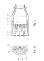
- Fig. 2 shows a can-combustor 110, which enables an individual combustion operation, and which will not have a harmful interaction among other individual can-combustors during the combustion operation.
- the can-combustor 110 comprises a number of removable premixed burners 10.
- the can-architecture in accordance with Figure 2 comprises a plurality of premixed burners 10 arranged on the can-combustor front face 15, which enables an individual combustion operation.
- the premixed burner 10 for example according to EP 0 704 657 A1 , consisting of a swirl generator, substantially according to EP 0 321 809 A1 , for a combustion air flow and means for injection of fuel , as well of a mixing path, formed of a mixing tube, provided downstream of said swirl generator, wherein said mixing path comprises transaction ducts extending within a first part of the path in the flow direction for transfer of a flow formed in said swirl generator into the cross-section of flow of said mixing path, that joins downstream of said transition ducts.
- the swirl generator according to EP 0 321 809 A1 consisting of hollow part-cone bodies making up a complete body, having tangential air inlet slots and feed channels for gaseous and liquid fuels, wherein in that the center-axes of the hollow part-cone bodies have a cone angle increasing in the direction of flow and run in the longitudinal direction at a mutual offset.
- the swirl intensity in the swirl generator is selected via its geometry in such a way that the vortex breakdown does not take place in the mixing tube but further downstream at the combustion chamber inlet.
- the length of the mixing tube is selected so that an adequate mixing quality for all types of fuel is obtained.
- the axial-velocity profile has a pronounced maximum on the axis and thereby prevents flash-backs in this region.
- the axial velocity decreases toward the wall.
- various measures are taken: On the one hand, for example, the overall velocity level can be raised through the use of a mixing tube having a sufficiently small diameter.
- the vortex breakdown is highly dependent from the design that the combustion chamber having a jump in cross-section adjoins the end of the mixing tube.
- a central backflow zone forms here the properties which are those of a flame retention baffle.
- premixed burners can be operated with liquid and/or gaseous fuels of all kinds.
- a premixed burner 10 can also be operated simultaneously with different fuels.
- a number of 6 segments 16 of acoustic liner are placed between the premixed burners 10. Upstream of every premixed burner 10 they are actively connected to an air-plenum 14 for subsequent efficient premixing operation.
- the gas turbine system comprises essentially at least one compressor, a first main-combustor which is connected downstream to the compressor.
- the hot gases of the first combustion chamber are admitted at least to an intermediate turbine or directly or indirectly to a second combustion chamber.
- the hot gases of the second combustion chamber are admitted to a further turbine or directly or indirectly to an energy recovery, for example to a steam generator
- the totality of the operated can-combustors of the first and/or second combustion chamber are designed and dis-posed as an annular can-architecture.
- Figure 2a shows the placing for a Helmholtz damper 11 and for a pilot nozzle 12 within the premixed burner arrangement of the can-combustors 110.
- a plurality of Helmholtz dampers 11 are taken place for damping of low frequency pressure oscillations connected to the combustion room though openings in the front of the can-combustor 10.
- a continuous or segmented acoustic liner 16 close to the combustor front face 15, optimized for damping of high frequency acoustic pressure oscillations.
- FIG. 2a in combination with Figure 2 shows a closed cooling loop 17 where the cooling air is flowing to a manifold, and is distributed to an impingement cavity, and after impingement cooling of the back side of the can-combustor front face 18 returns to the hood and enters the burner swirl generators 19.
- cooling air for the closed cooling loop is fed from an air source with higher static pressure than pressure in the hood as shown in Figure 2 .
- the combination of a premixed burner arrangement within a single can-combustor 110 thereby provides the opportunity to produce low emissions combustion at various load conditions of the gas turbine system. Furthermore, the optimized placing for a Helmholtz damper 11 and for a pilot nozzle 12, as shown in Fig 1 and 1a , or a continuous or segmented acoustic liner 16 within the premixed burner arrangement of every can-combustor 110 provides addition-ally the opportunity for reducing polluting emissions such as NOx and CO, while being able to provide stable combustion at lower load condition.
- can-combustor with respect to the Figure 2 can contain all features which have been described in the preceding Figure 1 .
- Figure 3 shows a can-combustor 120 comprising 2 x 3 removable burners 10, axially staged, with closed cooling according to the Figure 2 .
- the premixed burners of the can-combustor are divided in two groups ( Figures 3a and 3b ), each with one or more pre-mixed burners.
- the first one ( Figure 3a ) is positioned in the combustor face 15; the second one ( Figure 3b ) is positioned downstream of the first group in an axial position, where the blockage by the recirculation zones of the first group ( Figure 3a ) ceased.
- the premixed burners 10 of the second group ( Figure 3b ) operate in an oblique position with respect to the axial extension of the can-combustor 120.
- the size of the first group ( Figure 3a ) with respect to burner diameter and number of burners is chosen so that it can operate stable at low gas turbine part loads on low emissions, undisturbed by the cold airflow from the at part-load non-fired premixed burners of the second group ( Figure 3b ).
- the combination of sequential operating premixed burners in at least two groups within a single can-combustor 120 thereby provides the opportunity to produce low emissions combustion at various load conditions of the gas turbine system. Furthermore, the optimized placing for a Helmholtz damper (not shown) or a continuous or segmented acoustic liner 16 within the pre-mixed burner arrangement of every can-combustor 120 pro-vides additionally the opportunity for reducing polluting emissions such as NOx and CO, while being able to provide stable combustion at lower load condition.
- can-combustor with respect to the Figure 3 can contain all features which have been described in the preceding figures.
- Figure 4 and 4a show a can-combustor comprising 7 removable premixed burners, with one central burner 20 axially retracted to avoid interaction with the remaining burners 30.
- the totality of the premixed burners is divided in two groups.
- the first group consisting at least of one premixed burner, retracted axially to a position where its recirculation zone does not interact with the recirculation zones of the second group.
- the size of the first group 20 relating to burner diameter or number of burners is chosen so that it can operate stable at low gas turbine part loads on low emissions, undisturbed by the cold airflow from the at part-load non-fired second group premixed burners 30.
- can-combustor with respect to the Figure 4 can contain all features which have been described in the preceding figures.
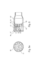
- Figure 5 and 5a show a can-combustor 140 comprising 6 premixed burners 40 with conical swirler and long lances 47, integrated with cap 44. Accordingly, the conical swirler and fuel lances are part of the can-combustor 40.
- the even distribution of the air to the individual pre-mixed burners 40 is supported, if required, by sieves positioned around the conical swirler or by a strainer 41 for equalizing of the airflow field, approaching the conical swirler.
- Conical swirler and fuel lances can be integrated with cap 44.
- the mixing tube 42 is integrated with acoustical front panel 43.
- a segmented Helmholtz cavity 45 is integrated with the acoustical front panel 43.
- the premixed burners 40 are equipped with premixed or non-premixed or partially premixed pilot nozzles 12 (see Figure 5a ) at burner's exit for ignition or reduction of the lean blow off temperature at part-load operation. Alternatively, a number of part-load pilot nozzles is placed in-between the premixed burners 40.
- the acoustical front panel 43 can be segmented and the segments tuned to control a variety of can-combustor high frequency pressure oscillations and to cool the face of the front panel 43.
- the segmented azimuthally conducted Helmholtz cavity in the hood is positioned between the mixing tubes. The segments of the cavity are individually connected by their necks 46 to the combustion room and individually tuned to control variety of the can-combustor low frequency pressure oscillations.
- can-combustor with respect to the Figure 5 can contain all features which have been described in the preceding figures.
Abstract
Description
- The invention refers to a gas turbine combustion system according to
claim 1 and 2. The invention refers additionally to a method for operating a gas turbine with a can-combustor comprising multiple premixed burners according to the description. -
US 6,935,116 B1 discloses a gas turbine combustion system for reducing polluting emissions such as NOx and CO, while being able to provide stable combustion at lower load conditions. The combustion system contains a casing having a center axis, which is in fluid communication with the engine compressor, and an end cover fixed to the casing. In the preferred embodiment, the end cover contains a plurality of first injectors arranged in a first array about the end cover and a plurality of second injectors arranged in a second array about the end cover, with the second array radially outward of the first array. Located proximate the end cover is a first swirler, also called swirl generator, having a plurality of passageways oriented generally perpendicular to the casing center axis for inducing a swirl generally radially inward to a first portion of the compressed air. Fuel, which is injected through the first and second injectors, mixes with the first portion of compressed air from the first swirler before entering a liner through a dome section. Additional fuel is also introduced to a second portion of com-pressed air through a plurality of third injectors located in a manifold of an aft injector assembly. The third injectors are divided into multiple circumferential sectors to allow for various fuels staging circumferentially around the aft injector assembly. To enhance mixing between fuel from the third injectors and second portion of compressed air, a second swirler is positioned adjacent the aft injector assembly for imparting a swirl to the second portion of compressed air. This fuel and air mixes in a second passage located between a first part of the liner and the dome prior to entering the liner and mixing with the fuel and first portion of compressed air from the first swirler region. Upon entering the liner, the pre-mixture from the second passage must undergo a complete reversal of flow direction that causes strong recirculation zones at the forward end of the liner. These recirculation zones help to increase combustor stability by providing a region where a portion of the hot combustion gases can be entrained and recirculate to provide continuous ignition to the incoming premixed fuel and compressed air. Fuel flow to each of the first, second, and third sets of injectors is controlled independently to allow for fuel staging throughout various load conditions to control NOx and CO emissions at each load set-ting. -
US 5,577,378 discloses a gas turbine group, comprising at least one compressor unit, a first combustion chamber for generating working gas, wherein the first combustion chamber connected to receive compressed air from the compressor unit. Furthermore, the first combustion chamber being an annular combustion chamber having a plurality of premixing premixed burners. A first turbine connected to receive working gas from the first combustion chamber. A second combustion chamber connected to receive exhausted working gas from the first turbine and deliver working gas to the second turbine. The second combustion chamber comprising an annular duct forming a combustion space extending in a flow direction from an outlet of the first turbine to an inlet of the second turbine; means for introducing fuel into the second combustion chamber for self-ignition of the fuel. A plurality of vortex generating elements mounted in the second combustion chamber upstream of the means for introducing fuel; and, a single rotor shaft supported by not more than two bearings, the at least one compressor unit, where-in first turbine and second turbine being connected on the rotor shaft, wherein the compressor unit consists of at least one compressor. The annular combustion chamber comprises a plurality of individual tubular units defining combustion spaces disposed circumferentially with respect to rotor shaft. The first turbine is configured for partially expanding the working gas so that working gas exhausted from the first turbine has a temperature sufficient for self ignition of a fuel in the second combustion chamber. The vortex generators in the second combustion chamber are shaped and positioned to each generate vortices in the flow. Accordingly, combustion systems of prior art, which utilise premixed burners according to the documentsEP 0 321 809 A1 and/orEP 0 704 657 A1 are of silo or annular design type, wherein these documents forming integral parts of the present description. - One of those premixed burners consisting of hollow part-cone bodies making up a complete body, having tangential air inlet slots and feed channels for gaseous and liquid fuels, wherein in that the centre axes of the hollow part-cone bodies have a cone angle increasing in the direction of flow and run in the longitudinal direction at a mutual offset. A fuel nozzle, which fuel injection is located in the middle of the connecting line of the mutually offset centre axes of the part-cone bodies, is placed at the premixed burner head in the conical interior formed by the part-cone bodies.
- An other premixed burner substantially consisting of a swirl generator, which substantially consisting of hollow part-cone bodies making up a complete body, having tangential air inlet slots and feed channels for gaseous and liquid fuels. The centre axes of the hollow part-cone bodies have a cone angle increasing in the direction of flow and run in the longitudinal direction at a mutual offset, wherein a fuel nozzle, which fuel injection is located in the middle of the connecting line of the mutually offset centre axes of the part-cone bodies, is placed at the premixed burner head in the conical interior formed by the part-cone bodies. A mixing path provided downstream of said swirl generator, wherein said mixing path comprises transaction ducts extending within a first part of the path in the flow direction for transfer of a flow formed in said swirl generator into the cross-section of flow of said mixing path, that joins downstream of said transition ducts.
- Compared to an annular type of design, the state of art does not offer un-confined a higher service-ability. The plurality of premixed burners distributed in circumferential direction does not give possibility to adjust an optimal combustion for each premixed burner load and type of fuel, due to operative interference of adjacent premixed burners.
-
EP 1 055 879 A1 -
EP 1 752 709 A2 - The present invention is based on the object of proposing an embodiment and a method for operating a gas turbine including a single or sequential combustion with low polluting emissions as NOx and CO and being able to provide stable combustion at the entire operation range, including the lower load conditions on gaseous and liquid fuels, which enables operation with reduced CO emissions.
- At least one combustion path of the gas turbine system utilizing at least one can-combustor chamber, and every can-combustor utilizing at least one premixed burner.
- The term "can-combustor" is a well-known technical term which refers to a self-contained cylindrical or quasi-cylindrical combustion chamber (tubular combustion space), which may be formed with different cross-sectional areas.
- The combustion chamber can consist of a single or a number of individual or with each other interdependent can-combustors, which are arranged in form of a horizontal, oblique, helical, etc., ring around the rotor axis.
- A first premix-premixed burner consisting of hollow part-cone bodies making up a complete body, having tangential air inlet slots and feed channels for gaseous and liquid fuels, wherein in that the center axes of the hollow part-cone bodies have a cone angle increasing in the direction of flow and run in the longitudinal direction at a mutual offset. A fuel nozzle, which fuel injection is located in the middle of the connecting line of the mutually offset center axes of the part-cone bodies, is placed at the premixed burner head in the conical interior formed by the part-cone bodies, according to the documents
EP 0 321 809 A1 , wherein this document forming integral part of the present description. - A further premix-premixed burner arrangement for a heat generator substantially consisting of a swirl generator, substantially according to
EP 0 321 809 A1 , for a combustion air flow and means for injection of fuel, as well of a mixing tube provided downstream of said swirl generator, wherein said mixing tube comprises transaction ducts extending within a first part of the mixing tube in the flow direction for transfer of a flow formed in said swirl generator into the cross-section of flow of said mixing tube, that joins downstream of said transition ducts, according to the documentEP 0 704 657 A1 , wherein this document forming integral part of the present description. - Further combustion burners comprising conical features of different types for a premix-combustion, namely: no-swirl-burners, burners with at least one axial, radial or conical swirler, or combination thereof for different flow passages.
- A can-combustor can be consisting of a combination of different premix-premixed burners, according at least to the above identified premixed burners.
- Mixing tube of the premixed burner can be integrated with the conical swirler or with the front face of the can-combustor. The clearance in the connection of conical swirler and the mixing tube is designed to allow for a small air flow entering the mixing tube and creating a flash back protecting air boundary layer. The mixing tube is straight or shaped at the exit to create the desired flow field at the exit to the can-combustor.
- Accordingly, the conical swirler is optimized dependent on and what type of a fuel lance is used.
- The primary premix gas injectors are placed in the optimized air slots of the conical swirler (see
EP 0 321 809 A1 ). The secondary gas premix injectors can be placed on the fuel-lance. The gas pilot injectors can be placed on the exit ring of the mixing tube or on the lance. Detached pilot gas injectors can be placed between the premixed burners. - The main oil injectors are placed on the lance or in the top of the conical swirler. The pilot oil injectors are placed on the exit ring of the mixing tube or on the fuel-lance. Detached pilot oil injectors can be placed between the premixed burners.
- All the burners can have the same rotational direction of the swirler or it can be combination of two burner groups, one co-rotation and the second counter-rotation swirl direction
- The described plurality of injection points and different types of injectors in different axial positions together with a possible axial distance between two premixed burner groups and azimuthally staging of the premixed burners provides conditions for optimal operation of the can-combustor over the whole operating range.
- Additionally, the combustion system consists of a pressure caring-casing, mounted on the turbine casing and being in fluid interconnecting with the engine compressor. The outgoing of the combustion system is in fluid communication with the turbine.
- Furthermore, the combustion system consists of components, each with a defined precise function. A hot combustor liner contains the combustion room and transfers the hot gases through an exit nozzle to the turbine. The hot side of the liner is heat protected advantageously by thermal barrier coating. On the outside of the combustor liner a cooling channel is formed by a shell and/or by the casing of the combustion system itself. The combustion air is flowing through this channel and cooling the hot combustor liner. To increase the cooling efficiency the surface of the liner is provided with turbulators, also called vortex generators (see
DE 103 30 023 A1 wherein this document forming integral part of the present description), and the height of the channel is chosen to create an optimal air velocity required for sufficient cooling at lowest possible pressure drop. It is further suggested to use the cooling holes at or near the vortex generators in a targeted manner for introducing an additional axial impulse. This can be achieved by modifying part of the cooling holes in such a way that an increased axial impulse is introduced into the core flow of the wave vortices. For this purpose, the geometry of the outlet openings is configured accordingly, for example with respect to their orientation and/or throughput. - For recovery of a dynamic pressure the exit of the cooling channel to the premixed burner hood is shaped advantageously as a diffuser. Equalizing of the airflow field in the premixed burner is possible in connection with a strainer with optimized distribution of holes, surrounding the hood. In an alternative design the strainer is, if required, replaced by individual sieves, at the inlet of each individual premixed burner.
- The number of the installed premixed burners with the conical swirlers according to the above identified embodiments is chosen optimally for the required power output of the combustion system and the required concept with consideration of the combustion stability and pollution emissions in the whole operation range.
- The total number of the premixed burners, absolute or relative to each can-combustor, can be split in two independent groups, separated from each other, both on the air side (separate hoods), and on the combustion size, with not interacting flames.
- Furthermore, the cap of the can-combustor is designed for an easy access to the pre-mixed burners and a service friendly handling of the system. The conical swirler and the fuel-lance can be integrated for dismantling with the cap, while the mixing tube is integrated with the front face. In case of design with a conical swirler integrated with the mixing tube (see
EP 0 704 657 A1 ) and eventually with a sieve each individual premixed burner can be dismantled separately. In this context, the fuel-lances are always designed for an individual dismantling. - Furthermore, the front face of the can-combustor can be cooled in an open cooling loop, where the cooling air is bypassing the conical swirlers in acoustic liner segments. In a closed cooling loop the cooling air returns to the hood after impingement cooling of the backside of the combustor front face, and to the swirlers.
- The invented design offers a plurality of means for control of the combustion dynamics for further improvement of the can-combustor operability. The high frequency combustion dynamics is, if necessary, controlled by segments of acoustic liner which is attached to the periphery of the combustor liner or by an acoustical front panel.
- The low frequency dynamics is, if necessary controlled by Helmholtz type of dampers. Dependent on the burner spacing, the damper is designated advantageously as a free-standing cylindrical Helmholtz cavity and neck or as a Helmholtz cavity in the free space between the mixing tubes, divided into sectors to prevent gas ingestion and allow for individual tuning. Additionally, the combustion dynamics can further be improved by tuning of the length of the mixing tubes, individually for each burner.
- The main advantages of the invented design are as follows, wherein the sequence does not reflect a rating:
- High serviceability compare to another design, wherein an annular design in combination with a can-architecture can be improved a favorable serviceability.
- Reduced development time and cost due the possibility for a complete "in house" development before implementing it in an engine.
- Tailoring of the combustion system for the next generation of the premixed burners with conical swirler and shaped mixing tubes.
- The relatively small size of the can-combustor allows for a cost effective sheet metal design. The engine service time and cost can be reduced in light of the fact that the can-combustor's cost and life is properly optimized.
- The compact size allows for a design with limited number of wearing and tearing parts and therefore for a low sensitivity for combustion dynamics.
- Possibility for implementing of axial-, radial-, azimuthal-staging, grouping of the pre-mixed burners in two or more positions, co-swirling or mixed co-swirling and counter-swirling burners.
- Implementation of acoustical and other passive damping devices for low emissions and controlled combustion dynamics over a wide operating range.
- The can-combustor can cover a wide range of engine sizes in light of its modular design. The size of the combustion system is limited only by size of the accessible high pressure combustion test plant. The number of can-combustors foe an engine is chosen based on the engine size.
- A can-combustor-architecture helps to reduce circumferential temperature gradients at the turbine inlet. These benefits in an increase of the lifetime of turbine parts.
- In terms of CO emissions for a can-combustor architecture the interaction between individual can-combustors is minimal or inexistent. On top of this leakages at the split plane, which are known to affect CO for annular concepts, will not impact the CO for a can-combustor engine, since for this architecture split line leak-ages into the combustor exist only at the latest end of the transition piece.
- Based on these findings the concept can be expected to work for an engine, which runs under sequential combustion (with or without an intermediate high pressure turbine) in a can-architecture, but not only.
- Basically, a single can-combustor comprising a number of premixed burners can be operated as a single combustion chamber.
- Referring to a sequential combustion the combination of two main-combustors (combustion chambers) can be disposed as follows.
- Principal embodiment: At least one combustion chamber is configured as annular can-combustor architecture, with at least one operating turbine.
- Principal embodiment: Both, the first and second combustion chambers are configured as sequential can-combustor architecture, with at least one operating turbine.
- Principal embodiment: Both, the first and second combustion chamber are configured as sequential can-combustor architecture with at least an intermediate operating turbine between the first and the second combustion chamber.
- Further embodiment: The first main-combustor is configured as an annular combustion chamber and the second main-combustor is built-on as a can configuration, with at least one operating turbine.
- Further embodiment: The first main-combustor is configured as a can-architecture and the second main-combustor is configured as an annular combustion chamber, with at least one operating turbine.
- Further embodiment: Both main-combustors, the first and second combustor, are configured as annular combustion chambers, with at least one operating turbine.
- Further embodiment: Both main-combustors, the first and second combustor, are configured as annular combustion chambers, with an intermediate operating turbine.
- The invention is shown schematically in
Fig. 1 to 5 based on exemplary embodiments. - Schematically, in the drawings:
-
Fig. 1, 1a show an individual can-combustor comprising 5 removable premixed burners; -
Fig. 2, 2a show an individual can-combustor comprising 7 removable premixed burners; -
Fig. 3, 3a, 3b show a can-combustor comprising 2 x 3 removable premixed burners, axially staged; -
Fig. 4, 4a show a can-combustor comprising 7 removable premixed burners, with one central burner axially retracted to avoid interaction with the remaining burners and -
Fig. 5, 5a show a can-combustion system with 6 premixed burners, integrated with cap, and with integrated acoustical front. -
Figure 1 shows a can-combustor 100, which enables an individual combustion operation, and which will be no harmful interaction among other individual can-combustors during the combustion operation. The can-combustor 100 comprises a number of re-movablepremixed burners 10. Thus, the can-architecture in accordance withFigure 1 comprises a plurality ofpremixed burners 10 arranged on the can-combustor front face 15, which enables an individual combustion operation. - The premixed
burner 10, for example according toEP 0 704 657 A1 , consisting of a swirl generator, substantially according toEP 0 321 809 A1 , for a combustion air flow and means for injection of fuel , as well of a mixing path, formed of a mixing tube, provided downstream of said swirl generator, wherein said mixing path comprises transaction ducts extending within a first part of the path in the flow direction for transfer of a flow formed in said swirl generator into the cross-section of flow of said mixing path, that joins downstream of said transition ducts. - The swirl generator according to
EP 0 321 809 A1 consisting of hollow part-cone bodies making up a complete body, having tangential air inlet slots and feed channels for gaseous and liquid fuels, wherein in that the center-axes of the hollow part-cone bodies have a cone angle increasing in the direction of flow and run in the longitudinal direction at a mutual offset. A fuel nozzle, which fuel injection is located in the middle of the connecting line of the mutually offset center-axes of the part-cone bodies, is placed at the burner head in the conical interior formed by the part-cone bodies. - The swirl intensity and swirl direction in the swirl generator is selected via its geometry in such a way that the vortex breakdown does not take place in the mixing tube but further downstream at the combustion chamber inlet. The length of the mixing tube is selected so that an adequate mixing quality for all types of fuel is obtained. In the mixing tube, the axial-velocity profile has a pronounced maximum on the axis and thereby prevents flash-backs in this region. The axial velocity decreases toward the wall. In order to also prevent flash-back in this area, various measures are taken: On the one hand, for example, the overall velocity level can be raised through the use of a mixing tube having a sufficiently small diameter. The vortex breakdown is highly dependent from the design that the combustion chamber having a jump in cross-section adjoins the end of the mixing tube. The ignition of the fuel/air-mixture starts at the premixed burner outlet and the flame is stabilized in the region of the premixed burner outlet by means of a backflow zone.
The documentsEP 0 321 809 A1 and/orEP 0 704 657 A1 forming an integral part of the present description. - In particular, said premixed burners can be operated with liquid and/or gaseous fuels of all kinds. Thus, it is readily possible to provide different fuels within the individual cans. This means also that a
premixed burner 10 can also be operated simultaneously with different fuels. - An acoustical
front panel 13 is placed on the can-combustor front face 15. Upstream of every premixedburner 10 they are actively connected to an air-plenum 14 for subsequent efficient premixing operation. - The gas turbine system comprises essentially at least one compressor, a first main-combustor which is connected downstream to the compressor. The hot gases of the first main-combustor are admitted at least to an intermediate turbine or directly or indirectly to a second main-combustor. The hot gases of the second combustion chamber are admitted to a further turbine or directly or indirectly to an energy recovery, for example to a steam generator
- Accordingly, implementing a sequential combustion path, the totality of the operated can-combustors of the first and/or second combustion chambers are designed and disposed as an annular can-architecture.
- Additionally,
Figure 1a shows the placing for aHelmholtz damper 11 and for apilot nozzle 12 within the premixed burner arrangement of the can-combustors 100. Furthermore, a plurality ofHelmholtz dampers 11 are taken place for damping of low frequency pressure oscillations connected to the combustion room though openings in the front-panel 13. - The combination of a premixed burner arrangement within a single can-
combustor 100 thereby provides the opportunity to produce low emissions combustion at various load conditions of the gas turbine system. Furthermore, the optimized placing for aHelmholtz damper 11 and for apilot nozzle 12 within the premixed burner arrangement of every can-combustor 100 provides additionally the opportunity for reducing polluting emissions such as NOx and CO, while being able to provide stable combustion at lower load condition. The premixed burner system can be equipped with non-premixed or partially premixed pilot nozzles 12at burner exit on the exit ring or on a fuel lance for ignition and reduction of the lean blow off temperature at part load operation. Alternatively, a number of part load pilot nozzles is placed in-between thepremixed burners 10. -
Fig. 2 shows a can-combustor 110, which enables an individual combustion operation, and which will not have a harmful interaction among other individual can-combustors during the combustion operation. The can-combustor 110 comprises a number of removablepremixed burners 10. Thus, the can-architecture in accordance withFigure 2 comprises a plurality ofpremixed burners 10 arranged on the can-combustor front face 15, which enables an individual combustion operation. - The premixed
burner 10, for example according toEP 0 704 657 A1 , consisting of a swirl generator, substantially according toEP 0 321 809 A1 , for a combustion air flow and means for injection of fuel , as well of a mixing path, formed of a mixing tube, provided downstream of said swirl generator, wherein said mixing path comprises transaction ducts extending within a first part of the path in the flow direction for transfer of a flow formed in said swirl generator into the cross-section of flow of said mixing path, that joins downstream of said transition ducts. - The swirl generator according to
EP 0 321 809 A1 consisting of hollow part-cone bodies making up a complete body, having tangential air inlet slots and feed channels for gaseous and liquid fuels, wherein in that the center-axes of the hollow part-cone bodies have a cone angle increasing in the direction of flow and run in the longitudinal direction at a mutual offset. A fuel nozzle, which fuel injection is located in the middle of the connecting line of the mutually offset center-axes of the part-cone bodies, is placed at the burner head in the conical interior formed by the part-cone bodies. - The swirl intensity in the swirl generator is selected via its geometry in such a way that the vortex breakdown does not take place in the mixing tube but further downstream at the combustion chamber inlet. The length of the mixing tube is selected so that an adequate mixing quality for all types of fuel is obtained. In the mixing tube, the axial-velocity profile has a pronounced maximum on the axis and thereby prevents flash-backs in this region. The axial velocity decreases toward the wall. In order to also prevent flash-back in this area, various measures are taken: On the one hand, for example, the overall velocity level can be raised through the use of a mixing tube having a sufficiently small diameter. The vortex breakdown is highly dependent from the design that the combustion chamber having a jump in cross-section adjoins the end of the mixing tube. A central backflow zone forms here the properties which are those of a flame retention baffle.
- The documents
EP 0 321 809 A1 and/orEP 0 704 657 A1 forming an integral part of the present description. - In particular, said premixed burners can be operated with liquid and/or gaseous fuels of all kinds. Thus, it is readily possible to provide different fuels within the individual cans. This means also that a
premixed burner 10 can also be operated simultaneously with different fuels. - A number of 6
segments 16 of acoustic liner are placed between thepremixed burners 10. Upstream of every premixedburner 10 they are actively connected to an air-plenum 14 for subsequent efficient premixing operation. - The gas turbine system comprises essentially at least one compressor, a first main-combustor which is connected downstream to the compressor. The hot gases of the first combustion chamber are admitted at least to an intermediate turbine or directly or indirectly to a second combustion chamber. The hot gases of the second combustion chamber are admitted to a further turbine or directly or indirectly to an energy recovery, for example to a steam generator
- Accordingly, implementing a sequential combustion path, the totality of the operated can-combustors of the first and/or second combustion chamber are designed and dis-posed as an annular can-architecture.
- Additionally,
Figure 2a shows the placing for aHelmholtz damper 11 and for apilot nozzle 12 within the premixed burner arrangement of the can-combustors 110. On the one hand, it is possible that a plurality ofHelmholtz dampers 11 are taken place for damping of low frequency pressure oscillations connected to the combustion room though openings in the front of the can-combustor 10. With respect toFigure 2 it is possible to dispose a continuous or segmentedacoustic liner 16 close to the combustorfront face 15, optimized for damping of high frequency acoustic pressure oscillations.Figure 2a in combination withFigure 2 shows aclosed cooling loop 17 where the cooling air is flowing to a manifold, and is distributed to an impingement cavity, and after impingement cooling of the back side of the can-combustor front face 18 returns to the hood and enters theburner swirl generators 19. For this procedure cooling air for the closed cooling loop is fed from an air source with higher static pressure than pressure in the hood as shown inFigure 2 . - The combination of a premixed burner arrangement within a single can-
combustor 110 thereby provides the opportunity to produce low emissions combustion at various load conditions of the gas turbine system. Furthermore, the optimized placing for aHelmholtz damper 11 and for apilot nozzle 12, as shown inFig 1 and 1a , or a continuous or segmentedacoustic liner 16 within the premixed burner arrangement of every can-combustor 110 provides addition-ally the opportunity for reducing polluting emissions such as NOx and CO, while being able to provide stable combustion at lower load condition. - Moreover, the can-combustor with respect to the
Figure 2 can contain all features which have been described in the precedingFigure 1 . -
Figure 3 shows a can-combustor 120 comprising 2 x 3removable burners 10, axially staged, with closed cooling according to theFigure 2 . The premixed burners of the can-combustor are divided in two groups (Figures 3a and 3b ), each with one or more pre-mixed burners. The first one (Figure 3a ) is positioned in thecombustor face 15; the second one (Figure 3b ) is positioned downstream of the first group in an axial position, where the blockage by the recirculation zones of the first group (Figure 3a ) ceased. The premixedburners 10 of the second group (Figure 3b ) operate in an oblique position with respect to the axial extension of the can-combustor 120. Accordingly, the size of the first group (Figure 3a ) with respect to burner diameter and number of burners is chosen so that it can operate stable at low gas turbine part loads on low emissions, undisturbed by the cold airflow from the at part-load non-fired premixed burners of the second group (Figure 3b ). - The combination of sequential operating premixed burners in at least two groups within a single can-
combustor 120 thereby provides the opportunity to produce low emissions combustion at various load conditions of the gas turbine system. Furthermore, the optimized placing for a Helmholtz damper (not shown) or a continuous or segmentedacoustic liner 16 within the pre-mixed burner arrangement of every can-combustor 120 pro-vides additionally the opportunity for reducing polluting emissions such as NOx and CO, while being able to provide stable combustion at lower load condition. - Moreover, the can-combustor with respect to the
Figure 3 can contain all features which have been described in the preceding figures. -
Figure 4 and 4a show a can-combustor comprising 7 removable premixed burners, with onecentral burner 20 axially retracted to avoid interaction with the remainingburners 30. The totality of the premixed burners is divided in two groups. The first group consisting at least of one premixed burner, retracted axially to a position where its recirculation zone does not interact with the recirculation zones of the second group. The size of thefirst group 20 relating to burner diameter or number of burners is chosen so that it can operate stable at low gas turbine part loads on low emissions, undisturbed by the cold airflow from the at part-load non-fired second group premixed burners 30. - Moreover, the can-combustor with respect to the
Figure 4 can contain all features which have been described in the preceding figures. -
Figure 5 and 5a show a can-combustor 140 comprising 6 premixedburners 40 with conical swirler andlong lances 47, integrated withcap 44. Accordingly, the conical swirler and fuel lances are part of the can-combustor 40. The even distribution of the air to the individualpre-mixed burners 40 is supported, if required, by sieves positioned around the conical swirler or by astrainer 41 for equalizing of the airflow field, approaching the conical swirler. Conical swirler and fuel lances can be integrated withcap 44. The mixingtube 42 is integrated with acousticalfront panel 43. Asegmented Helmholtz cavity 45 is integrated with the acousticalfront panel 43. The premixedburners 40 are equipped with premixed or non-premixed or partially premixed pilot nozzles 12 (seeFigure 5a ) at burner's exit for ignition or reduction of the lean blow off temperature at part-load operation. Alternatively, a number of part-load pilot nozzles is placed in-between thepremixed burners 40. The acousticalfront panel 43 can be segmented and the segments tuned to control a variety of can-combustor high frequency pressure oscillations and to cool the face of thefront panel 43. The segmented azimuthally conducted Helmholtz cavity in the hood is positioned between the mixing tubes. The segments of the cavity are individually connected by theirnecks 46 to the combustion room and individually tuned to control variety of the can-combustor low frequency pressure oscillations. - Moreover, the can-combustor with respect to the
Figure 5 can contain all features which have been described in the preceding figures. - Obviously, numerous modifications and variations of the present invention are possible in light of the above teachings. It is therefore to be understood that within the scope of the appended claims, the invention may be practiced otherwise than as specifically described herein.
Claims (13)
- Gas turbine combustion system, wherein the gas turbine comprises at least one compressor, at least one combustion chamber for generating working gas, wherein the combustion chamber connected to receive compressed air from the compressor, at least one turbine connected to receive working gas from the combustion chamber, wherein the combustion chamber consists of a single can-combustor or comprising a number of individual or interdependent can-combustors arranged in an annular can-architecture, wherein the can-combustor having at least one premixed burner, wherein the ignition of the mixture starts at the premixed burner outlet and the flame is stabilized in the region of the premixed burner outlet by means of a backflow zone, wherein the can-combustor comprising a number of premixed burners arranged uniformly or divided at least in two groups within the can-combustor.
- Gas turbine combustion system, wherein the gas turbine comprises at least one compressor, a first combustion chamber for generating working gas, wherein the first combustion chamber connected to receive compressed air from the compressor, wherein the hot gases of the first combustion chamber are admitted at least to an intermediate turbine or directly or indirectly to a second combustion chamber, wherein the hot gases of the second combustor are admitted to a further turbine or directly or indirectly to an energy recovery, wherein the first and/or the second combustion chamber consists of a single can-combustor or comprising a number of individual or interdependent can-combustors arranged in an annular can-architecture, wherein the can-combustor having at least one premixed burner, wherein the ignition of the mixture starts at the premixed burner outlet and the flame is stabilized in the region of the premixed burner outlet by means of a backflow zone, and wherein the can-combustor comprising a number of premixed burners arranged uniformly or divided at least in two groups within the can-combustor.
- Gas turbine combustion system as claimed in one of the claims 1 to 2, characterized in that at least one premixed burner is axially retracted with respect to the remaining pre-mixed burners.
- Gas turbine combustion system as claimed in one of the claims 1 to 2, characterized in that the premixed burners of the can-combustor are divided in two groups, each with one or more premixed burners, wherein the first one is positioned in the can-combustor face and the second one is positioned downstream of the first group in an axial position, wherein the premixed burners of the second group operating in an oblique position with respect to the axial extension of the can-combustor.
- Gas turbine combustion system as claimed in one of the claims 1 to 4, characterized in that the premixed burner substantially consisting of a swirl generator, which substantially consisting of hollow part-cone bodies making up a complete body, having tangential air inlet slots and feed channels for gaseous and liquid fuels, wherein in that the center axes of the hollow part-cone bodies have a cone angle increasing in the direction of flow and run in the longitudinal direction at a mutual offset, wherein a fuel nozzle, which fuel injection is located in the middle of the connecting line of the mutually offset center axes of the part-cone bodies, is placed at the burner head in the conical interior formed by the part-cone bodies, and as well of a mixing tube provided downstream of said swirl generator, wherein said mixing tube comprises transaction ducts extending within a first part of the path in the flow direction for transfer of a flow formed in said swirl generator into the cross-section of flow of said mixing tube, that joins downstream of said transition ducts.
- Gas turbine combustion system as claimed in claim 5, characterized in that the swirl generator consisting of hollow part-cone bodies making up a complete body, having tangential air inlet slots and feed channels for gaseous and/or liquid fuels, wherein in that the center axes of the hollow part-cone bodies have a cone angle increasing in the direction of flow and run in the longitudinal direction at a mutual offset, wherein a fuel nozzle, which fuel injection is located in the middle of the connecting line of the mutually offset center axes of the part-cone bodies, is placed at the burner head in the conical interior formed by the part-cone bodies.
- Gas turbine combustion system as claimed in claim 5, characterized in that the mixing tube is shaped with variable diameter and/or length along the axis of the premixed burner.
- Gas turbine combustion system as claimed in one of the claims 1 to 7, characterized in that the premixed burner is equipped with premixed, or partially pre-mixed or non-premixed pilot nozzle for ignition and reduction of the lean blow off temperature at part-load operation.
- Gas turbine combustion system as claimed in one of the claims 5 to 8, characterized in that the pilot nozzle is arranged at the premixed burner's exit, or on the fuel lance of the swirl generator, or is placed in-between the premixed burner.
- Gas turbine combustion system as claimed in one of the claims 1 to 9, characterized in that the low frequency dynamics of the can-combustor is controlled by Helmholtz damper, wherein the Helmholtz damper is designated as a freestanding cylindrical Helmholtz cavity and neck, or as Helmholtz cavity in the free space between the mixing tubes of the premixed burners.
- Gas turbine combustion system as claimed in claim 10, characterized in that the Helmholtz dampers are divided into sectors of the premixed burner group to prevent low frequency pressure oscillations.
- Gas turbine combustion system as claimed in one of the claims 1 to 11, characterized in that the can-combustor front face is designed as an acoustic damper for damping of high frequency acoustic pressure oscillations.
- Gas turbine combustion system as claimed in claims 1 to 12, characterized in that the distribution of the compressed air from the compressor to the individual premixed burners is supported by sieves which are positioned around of the conical swirl generators or by a strainer.
Priority Applications (1)
| Application Number | Priority Date | Filing Date | Title |
|---|---|---|---|
| EP13175507.6A EP2685172B1 (en) | 2012-07-09 | 2013-07-08 | Can-annular gas turbine unit with staged premix-combustion |
Applications Claiming Priority (2)
| Application Number | Priority Date | Filing Date | Title |
|---|---|---|---|
| EP12175593 | 2012-07-09 | ||
| EP13175507.6A EP2685172B1 (en) | 2012-07-09 | 2013-07-08 | Can-annular gas turbine unit with staged premix-combustion |
Publications (3)
| Publication Number | Publication Date |
|---|---|
| EP2685172A2 true EP2685172A2 (en) | 2014-01-15 |
| EP2685172A3 EP2685172A3 (en) | 2014-04-16 |
| EP2685172B1 EP2685172B1 (en) | 2018-03-21 |
Family
ID=48703362
Family Applications (1)
| Application Number | Title | Priority Date | Filing Date |
|---|---|---|---|
| EP13175507.6A Active EP2685172B1 (en) | 2012-07-09 | 2013-07-08 | Can-annular gas turbine unit with staged premix-combustion |
Country Status (7)
| Country | Link |
|---|---|
| US (1) | US9810152B2 (en) |
| EP (1) | EP2685172B1 (en) |
| JP (1) | JP5933491B2 (en) |
| KR (1) | KR101563526B1 (en) |
| CN (1) | CN103542427B (en) |
| CA (1) | CA2820082C (en) |
| RU (1) | RU2561956C2 (en) |
Cited By (7)
| Publication number | Priority date | Publication date | Assignee | Title |
|---|---|---|---|---|
| EP2975326A1 (en) * | 2014-07-18 | 2016-01-20 | United Technologies Corporation | Combustor assembly for a turbine engine |
| EP3228939A1 (en) * | 2016-04-08 | 2017-10-11 | Ansaldo Energia Switzerland AG | Method for combusting a fuel, and combustion appliance |
| US11255545B1 (en) | 2020-10-26 | 2022-02-22 | General Electric Company | Integrated combustion nozzle having a unified head end |
| US11371702B2 (en) | 2020-08-31 | 2022-06-28 | General Electric Company | Impingement panel for a turbomachine |
| US11460191B2 (en) | 2020-08-31 | 2022-10-04 | General Electric Company | Cooling insert for a turbomachine |
| US11614233B2 (en) | 2020-08-31 | 2023-03-28 | General Electric Company | Impingement panel support structure and method of manufacture |
| US11767766B1 (en) | 2022-07-29 | 2023-09-26 | General Electric Company | Turbomachine airfoil having impingement cooling passages |
Families Citing this family (17)
| Publication number | Priority date | Publication date | Assignee | Title |
|---|---|---|---|---|
| US9958162B2 (en) | 2011-01-24 | 2018-05-01 | United Technologies Corporation | Combustor assembly for a turbine engine |
| EP2796789B1 (en) * | 2013-04-26 | 2017-03-01 | General Electric Technology GmbH | Can combustor for a can-annular combustor arrangement in a gas turbine |
| EP3002518B1 (en) * | 2014-09-30 | 2019-01-30 | Ansaldo Energia Switzerland AG | Combustor front panel |
| KR102488572B1 (en) * | 2015-05-06 | 2023-01-13 | 한화파워시스템 주식회사 | Product design method and compressor design method adopting the method |
| CA3017491C (en) * | 2016-03-15 | 2023-02-07 | Jay Keller | Non-premixed swirl burner tip and combustion strategy |
| KR102063169B1 (en) * | 2017-07-04 | 2020-01-07 | 두산중공업 주식회사 | Fuel nozzle assembly and combustor and gas turbine having the same |
| US10941939B2 (en) * | 2017-09-25 | 2021-03-09 | General Electric Company | Gas turbine assemblies and methods |
| US10890329B2 (en) | 2018-03-01 | 2021-01-12 | General Electric Company | Fuel injector assembly for gas turbine engine |
| US10935245B2 (en) | 2018-11-20 | 2021-03-02 | General Electric Company | Annular concentric fuel nozzle assembly with annular depression and radial inlet ports |
| US11073114B2 (en) | 2018-12-12 | 2021-07-27 | General Electric Company | Fuel injector assembly for a heat engine |
| US11286884B2 (en) | 2018-12-12 | 2022-03-29 | General Electric Company | Combustion section and fuel injector assembly for a heat engine |
| US11156360B2 (en) | 2019-02-18 | 2021-10-26 | General Electric Company | Fuel nozzle assembly |
| DE102019204544A1 (en) * | 2019-04-01 | 2020-10-01 | Siemens Aktiengesellschaft | Tube combustion chamber system and gas turbine system with such a tube combustion chamber system |
| US11156164B2 (en) | 2019-05-21 | 2021-10-26 | General Electric Company | System and method for high frequency accoustic dampers with caps |
| US11174792B2 (en) | 2019-05-21 | 2021-11-16 | General Electric Company | System and method for high frequency acoustic dampers with baffles |
| US11686474B2 (en) | 2021-03-04 | 2023-06-27 | General Electric Company | Damper for swirl-cup combustors |
| KR102583224B1 (en) | 2022-01-26 | 2023-09-25 | 두산에너빌리티 주식회사 | Combustor with cluster and gas turbine including same |
Citations (7)
| Publication number | Priority date | Publication date | Assignee | Title |
|---|---|---|---|---|
| EP0321809A1 (en) | 1987-12-21 | 1989-06-28 | BBC Brown Boveri AG | Process for combustion of liquid fuel in a burner |
| EP0704657A2 (en) | 1994-10-01 | 1996-04-03 | ABB Management AG | Burner |
| US5577378A (en) | 1993-04-08 | 1996-11-26 | Abb Management Ag | Gas turbine group with reheat combustor |
| EP1055879A1 (en) | 1999-05-22 | 2000-11-29 | Rolls-Royce Plc | A combustion chamber assembly and a method of operating a combustion chamber assembly |
| DE10330023A1 (en) | 2002-07-20 | 2004-02-05 | Alstom (Switzerland) Ltd. | Vortex generator used in the swirling and mixing of fuel/air mixtures in pre-mixing combustion chambers comprises an outlet opening for targeted introduction of a secondary flow into the core flow of the wake produced |
| US6935116B2 (en) | 2003-04-28 | 2005-08-30 | Power Systems Mfg., Llc | Flamesheet combustor |
| EP1752709A2 (en) | 2005-08-10 | 2007-02-14 | General Electric Company | Reheat combustion in gas turbine systems |
Family Cites Families (35)
| Publication number | Priority date | Publication date | Assignee | Title |
|---|---|---|---|---|
| US2614385A (en) * | 1946-01-14 | 1952-10-21 | Power Jets Res & Dev Ltd | Supporting structure for gas turbine power plants |
| US3315467A (en) * | 1965-03-11 | 1967-04-25 | Westinghouse Electric Corp | Reheat gas turbine power plant with air admission to the primary combustion zone of the reheat combustion chamber structure |
| DE2629761A1 (en) * | 1976-07-02 | 1978-01-05 | Volkswagenwerk Ag | COMBUSTION CHAMBER FOR GAS TURBINES |
| FR2392231A1 (en) * | 1977-05-23 | 1978-12-22 | Inst Francais Du Petrole | GAS TURBINE WITH A COMBUSTION CHAMBER BETWEEN THE STAGES OF THE TURBINE |
| US4910957A (en) | 1988-07-13 | 1990-03-27 | Prutech Ii | Staged lean premix low nox hot wall gas turbine combustor with improved turndown capability |
| DE4223828A1 (en) | 1992-05-27 | 1993-12-02 | Asea Brown Boveri | Method for operating a combustion chamber of a gas turbine |
| DE59208831D1 (en) * | 1992-06-29 | 1997-10-02 | Abb Research Ltd | Combustion chamber of a gas turbine |
| CH687831A5 (en) * | 1993-04-08 | 1997-02-28 | Asea Brown Boveri | Premix burner. |
| EP0646705B1 (en) * | 1993-09-06 | 1999-06-09 | Asea Brown Boveri Ag | Method for providing partial load operation in a gas turbine plant |
| DE4411623A1 (en) * | 1994-04-02 | 1995-10-05 | Abb Management Ag | Premix burner |
| GB9410233D0 (en) * | 1994-05-21 | 1994-07-06 | Rolls Royce Plc | A gas turbine engine combustion chamber |
| CH688899A5 (en) * | 1994-05-26 | 1998-05-15 | Asea Brown Boveri | A method for controlling a gas turbine group. |
| DE4426351B4 (en) * | 1994-07-25 | 2006-04-06 | Alstom | Combustion chamber for a gas turbine |
| US5943866A (en) * | 1994-10-03 | 1999-08-31 | General Electric Company | Dynamically uncoupled low NOx combustor having multiple premixers with axial staging |
| US5644918A (en) * | 1994-11-14 | 1997-07-08 | General Electric Company | Dynamics free low emissions gas turbine combustor |
| US5687571A (en) * | 1995-02-20 | 1997-11-18 | Asea Brown Boveri Ag | Combustion chamber with two-stage combustion |
| JPH0988628A (en) | 1995-09-26 | 1997-03-31 | Toshiba Corp | Reheating type gas turbine plant |
| DE19537637A1 (en) * | 1995-10-10 | 1997-04-17 | Asea Brown Boveri | Process for operating a power plant |
| DE19547913A1 (en) * | 1995-12-21 | 1997-06-26 | Abb Research Ltd | Burners for a heat generator |
| CN1162089A (en) | 1995-12-21 | 1997-10-15 | Abb研究有限公司 | Combustion device of heat generator |
| DE19615910B4 (en) * | 1996-04-22 | 2006-09-14 | Alstom | burner arrangement |
| GB2319078B (en) * | 1996-11-08 | 1999-11-03 | Europ Gas Turbines Ltd | Combustor arrangement |
| US6269646B1 (en) * | 1998-01-28 | 2001-08-07 | General Electric Company | Combustors with improved dynamics |
| EP0935095A3 (en) * | 1998-02-09 | 2000-07-19 | Mitsubishi Heavy Industries, Ltd. | Gas turbine combustor |
| SE9802707L (en) * | 1998-08-11 | 2000-02-12 | Abb Ab | Burner chamber device and method for reducing the influence of acoustic pressure fluctuations in a burner chamber device |
| JP4610796B2 (en) * | 2001-06-13 | 2011-01-12 | 三菱重工業株式会社 | Gas turbine combustor |
| JP4610800B2 (en) * | 2001-06-29 | 2011-01-12 | 三菱重工業株式会社 | Gas turbine combustor |
| WO2003060381A1 (en) * | 2002-01-16 | 2003-07-24 | Alstom Technology Ltd | Combustion chamber and damper arrangement for reduction of combustion chamber pulsations in a gas turbine plant |
| DE102004009226A1 (en) * | 2003-03-07 | 2004-09-16 | Alstom Technology Ltd | Burn control for gas turbine engine has a lean mixture input burn chamber linked to the main burn chamber via a double walled porous element |
| JP2009156542A (en) * | 2007-12-27 | 2009-07-16 | Mitsubishi Heavy Ind Ltd | Burner for gas turbine |
| US8516819B2 (en) * | 2008-07-16 | 2013-08-27 | Siemens Energy, Inc. | Forward-section resonator for high frequency dynamic damping |
| US8176739B2 (en) * | 2008-07-17 | 2012-05-15 | General Electric Company | Coanda injection system for axially staged low emission combustors |
| CH700796A1 (en) | 2009-04-01 | 2010-10-15 | Alstom Technology Ltd | Method for CO-emission operation of a gas turbine with sequential combustion and gas turbine with improved part-load emission behavior. |
| RU2447304C2 (en) * | 2010-03-19 | 2012-04-10 | Общество с ограниченной ответственностью Финансово-промышленная компания "Космос-Нефть-Газ" | Gas turbine plant |
| US8590311B2 (en) * | 2010-04-28 | 2013-11-26 | General Electric Company | Pocketed air and fuel mixing tube |
-
2013
- 2013-06-24 RU RU2013128796/06A patent/RU2561956C2/en active
- 2013-07-08 US US13/936,310 patent/US9810152B2/en active Active
- 2013-07-08 CA CA2820082A patent/CA2820082C/en not_active Expired - Fee Related
- 2013-07-08 EP EP13175507.6A patent/EP2685172B1/en active Active
- 2013-07-08 KR KR1020130079571A patent/KR101563526B1/en not_active IP Right Cessation
- 2013-07-09 CN CN201310286007.XA patent/CN103542427B/en active Active
- 2013-07-09 JP JP2013143565A patent/JP5933491B2/en not_active Expired - Fee Related
Patent Citations (7)
| Publication number | Priority date | Publication date | Assignee | Title |
|---|---|---|---|---|
| EP0321809A1 (en) | 1987-12-21 | 1989-06-28 | BBC Brown Boveri AG | Process for combustion of liquid fuel in a burner |
| US5577378A (en) | 1993-04-08 | 1996-11-26 | Abb Management Ag | Gas turbine group with reheat combustor |
| EP0704657A2 (en) | 1994-10-01 | 1996-04-03 | ABB Management AG | Burner |
| EP1055879A1 (en) | 1999-05-22 | 2000-11-29 | Rolls-Royce Plc | A combustion chamber assembly and a method of operating a combustion chamber assembly |
| DE10330023A1 (en) | 2002-07-20 | 2004-02-05 | Alstom (Switzerland) Ltd. | Vortex generator used in the swirling and mixing of fuel/air mixtures in pre-mixing combustion chambers comprises an outlet opening for targeted introduction of a secondary flow into the core flow of the wake produced |
| US6935116B2 (en) | 2003-04-28 | 2005-08-30 | Power Systems Mfg., Llc | Flamesheet combustor |
| EP1752709A2 (en) | 2005-08-10 | 2007-02-14 | General Electric Company | Reheat combustion in gas turbine systems |
Cited By (7)
| Publication number | Priority date | Publication date | Assignee | Title |
|---|---|---|---|---|
| EP2975326A1 (en) * | 2014-07-18 | 2016-01-20 | United Technologies Corporation | Combustor assembly for a turbine engine |
| EP3228939A1 (en) * | 2016-04-08 | 2017-10-11 | Ansaldo Energia Switzerland AG | Method for combusting a fuel, and combustion appliance |
| US11371702B2 (en) | 2020-08-31 | 2022-06-28 | General Electric Company | Impingement panel for a turbomachine |
| US11460191B2 (en) | 2020-08-31 | 2022-10-04 | General Electric Company | Cooling insert for a turbomachine |
| US11614233B2 (en) | 2020-08-31 | 2023-03-28 | General Electric Company | Impingement panel support structure and method of manufacture |
| US11255545B1 (en) | 2020-10-26 | 2022-02-22 | General Electric Company | Integrated combustion nozzle having a unified head end |
| US11767766B1 (en) | 2022-07-29 | 2023-09-26 | General Electric Company | Turbomachine airfoil having impingement cooling passages |
Also Published As
| Publication number | Publication date |
|---|---|
| CN103542427B (en) | 2016-08-24 |
| CN103542427A (en) | 2014-01-29 |
| JP5933491B2 (en) | 2016-06-08 |
| US20140007578A1 (en) | 2014-01-09 |
| CA2820082C (en) | 2016-02-23 |
| KR101563526B1 (en) | 2015-10-27 |
| EP2685172A3 (en) | 2014-04-16 |
| EP2685172B1 (en) | 2018-03-21 |
| JP2014016146A (en) | 2014-01-30 |
| KR20140007286A (en) | 2014-01-17 |
| CA2820082A1 (en) | 2014-01-09 |
| RU2013128796A (en) | 2014-12-27 |
| RU2561956C2 (en) | 2015-09-10 |
| US9810152B2 (en) | 2017-11-07 |
Similar Documents
| Publication | Publication Date | Title |
|---|---|---|
| US9810152B2 (en) | Gas turbine combustion system | |
| JP5855049B2 (en) | Burner arrangement | |
| US8959921B2 (en) | Flame tolerant secondary fuel nozzle | |
| US7950233B2 (en) | Combustor | |
| JP2019509460A (en) | Split annular combustion system with axial fuel multi-stage | |
| EP2837883B1 (en) | Premixed can annular combustor with mixing lobes for the second stage of a sequential gas turbine | |
| EP2993404B1 (en) | Dilution gas or air mixer for a combustor of a gas turbine | |
| CN105715378B (en) | Separate supply of cooling and dilution air | |
| US9052114B1 (en) | Tangential annular combustor with premixed fuel and air for use on gas turbine engines | |
| US10215417B2 (en) | Sequential combustor arrangement with a mixer | |
| KR101774630B1 (en) | Tangential annular combustor with premixed fuel and air for use on gas turbine engines | |
| US9181812B1 (en) | Can-annular combustor with premixed tangential fuel-air nozzles for use on gas turbine engines | |
| EP2515041B1 (en) | Fuel Nozzle And Method For Operating A Combustor | |
| WO2014173578A1 (en) | Sequential combustion with dilution gas | |
| EP2989389B1 (en) | Sequential combustion with dilution gas |
Legal Events
| Date | Code | Title | Description |
|---|---|---|---|
| PUAI | Public reference made under article 153(3) epc to a published international application that has entered the european phase |
Free format text: ORIGINAL CODE: 0009012 |
|
| AK | Designated contracting states |
Kind code of ref document: A2 Designated state(s): AL AT BE BG CH CY CZ DE DK EE ES FI FR GB GR HR HU IE IS IT LI LT LU LV MC MK MT NL NO PL PT RO RS SE SI SK SM TR |
|
| AX | Request for extension of the european patent |
Extension state: BA ME |
|
| RIN1 | Information on inventor provided before grant (corrected) |
Inventor name: CERNY, JAN Inventor name: ALURI, NARESH Inventor name: PASQUALOTTO, ENNIO Inventor name: GENIN, FRANKLIN MARIE Inventor name: EROGLU, ADNAN |
|
| PUAL | Search report despatched |
Free format text: ORIGINAL CODE: 0009013 |
|
| AK | Designated contracting states |
Kind code of ref document: A3 Designated state(s): AL AT BE BG CH CY CZ DE DK EE ES FI FR GB GR HR HU IE IS IT LI LT LU LV MC MK MT NL NO PL PT RO RS SE SI SK SM TR |
|
| AX | Request for extension of the european patent |
Extension state: BA ME |
|
| RIC1 | Information provided on ipc code assigned before grant |
Ipc: F23R 3/46 20060101ALI20140307BHEP Ipc: F23R 3/34 20060101ALI20140307BHEP Ipc: F23C 6/04 20060101ALN20140307BHEP Ipc: F23R 3/28 20060101ALI20140307BHEP Ipc: F02C 3/14 20060101AFI20140307BHEP Ipc: F02C 6/00 20060101ALI20140307BHEP |
|
| 17P | Request for examination filed |
Effective date: 20140611 |
|
| RBV | Designated contracting states (corrected) |
Designated state(s): AL AT BE BG CH CY CZ DE DK EE ES FI FR GB GR HR HU IE IS IT LI LT LU LV MC MK MT NL NO PL PT RO RS SE SI SK SM TR |
|
| 17Q | First examination report despatched |
Effective date: 20160303 |
|
| RAP1 | Party data changed (applicant data changed or rights of an application transferred) |
Owner name: GENERAL ELECTRIC TECHNOLOGY GMBH |
|
| RAP1 | Party data changed (applicant data changed or rights of an application transferred) |
Owner name: ANSALDO ENERGIA SWITZERLAND AG |
|
| REG | Reference to a national code |
Ref country code: DE Ref legal event code: R079 Ref document number: 602013034618 Country of ref document: DE Free format text: PREVIOUS MAIN CLASS: F23R0003280000 Ipc: F02C0003140000 |
|
| RIC1 | Information provided on ipc code assigned before grant |
Ipc: F23R 3/34 20060101ALI20170731BHEP Ipc: F02C 6/00 20060101ALI20170731BHEP Ipc: F23C 6/04 20060101ALN20170731BHEP Ipc: F02C 3/14 20060101AFI20170731BHEP Ipc: F23M 20/00 20140101ALI20170731BHEP Ipc: F23R 3/46 20060101ALI20170731BHEP Ipc: F23R 3/28 20060101ALI20170731BHEP |
|
| RIC1 | Information provided on ipc code assigned before grant |
Ipc: F23R 3/46 20060101ALI20170809BHEP Ipc: F02C 6/00 20060101ALI20170809BHEP Ipc: F23M 20/00 20140101ALI20170809BHEP Ipc: F23R 3/34 20060101ALI20170809BHEP Ipc: F23C 6/04 20060101ALN20170809BHEP Ipc: F23R 3/28 20060101ALI20170809BHEP Ipc: F02C 3/14 20060101AFI20170809BHEP |
|
| RIC1 | Information provided on ipc code assigned before grant |
Ipc: F23R 3/46 20060101ALI20170816BHEP Ipc: F02C 3/14 20060101AFI20170816BHEP Ipc: F02C 6/00 20060101ALI20170816BHEP Ipc: F23M 20/00 20140101ALI20170816BHEP Ipc: F23R 3/28 20060101ALI20170816BHEP Ipc: F23R 3/34 20060101ALI20170816BHEP Ipc: F23C 6/04 20060101ALN20170816BHEP |
|
| GRAP | Despatch of communication of intention to grant a patent |
Free format text: ORIGINAL CODE: EPIDOSNIGR1 |
|
| INTG | Intention to grant announced |
Effective date: 20171004 |
|
| GRAS | Grant fee paid |
Free format text: ORIGINAL CODE: EPIDOSNIGR3 |
|
| GRAA | (expected) grant |
Free format text: ORIGINAL CODE: 0009210 |
|
| AK | Designated contracting states |
Kind code of ref document: B1 Designated state(s): AL AT BE BG CH CY CZ DE DK EE ES FI FR GB GR HR HU IE IS IT LI LT LU LV MC MK MT NL NO PL PT RO RS SE SI SK SM TR |
|
| REG | Reference to a national code |
Ref country code: GB Ref legal event code: FG4D |
|
| REG | Reference to a national code |
Ref country code: CH Ref legal event code: EP |
|
| REG | Reference to a national code |
Ref country code: AT Ref legal event code: REF Ref document number: 981369 Country of ref document: AT Kind code of ref document: T Effective date: 20180415 |
|
| REG | Reference to a national code |
Ref country code: IE Ref legal event code: FG4D |
|
| REG | Reference to a national code |
Ref country code: DE Ref legal event code: R096 Ref document number: 602013034618 Country of ref document: DE |
|
| REG | Reference to a national code |
Ref country code: NL Ref legal event code: MP Effective date: 20180321 |
|
| PG25 | Lapsed in a contracting state [announced via postgrant information from national office to epo] |
Ref country code: FI Free format text: LAPSE BECAUSE OF FAILURE TO SUBMIT A TRANSLATION OF THE DESCRIPTION OR TO PAY THE FEE WITHIN THE PRESCRIBED TIME-LIMIT Effective date: 20180321 Ref country code: NO Free format text: LAPSE BECAUSE OF FAILURE TO SUBMIT A TRANSLATION OF THE DESCRIPTION OR TO PAY THE FEE WITHIN THE PRESCRIBED TIME-LIMIT Effective date: 20180621 Ref country code: CY Free format text: LAPSE BECAUSE OF FAILURE TO SUBMIT A TRANSLATION OF THE DESCRIPTION OR TO PAY THE FEE WITHIN THE PRESCRIBED TIME-LIMIT Effective date: 20180321 Ref country code: HR Free format text: LAPSE BECAUSE OF FAILURE TO SUBMIT A TRANSLATION OF THE DESCRIPTION OR TO PAY THE FEE WITHIN THE PRESCRIBED TIME-LIMIT Effective date: 20180321 Ref country code: LT Free format text: LAPSE BECAUSE OF FAILURE TO SUBMIT A TRANSLATION OF THE DESCRIPTION OR TO PAY THE FEE WITHIN THE PRESCRIBED TIME-LIMIT Effective date: 20180321 |
|
| REG | Reference to a national code |
Ref country code: LT Ref legal event code: MG4D |
|
| REG | Reference to a national code |
Ref country code: AT Ref legal event code: MK05 Ref document number: 981369 Country of ref document: AT Kind code of ref document: T Effective date: 20180321 |
|
| PG25 | Lapsed in a contracting state [announced via postgrant information from national office to epo] |
Ref country code: GR Free format text: LAPSE BECAUSE OF FAILURE TO SUBMIT A TRANSLATION OF THE DESCRIPTION OR TO PAY THE FEE WITHIN THE PRESCRIBED TIME-LIMIT Effective date: 20180622 Ref country code: LV Free format text: LAPSE BECAUSE OF FAILURE TO SUBMIT A TRANSLATION OF THE DESCRIPTION OR TO PAY THE FEE WITHIN THE PRESCRIBED TIME-LIMIT Effective date: 20180321 Ref country code: SE Free format text: LAPSE BECAUSE OF FAILURE TO SUBMIT A TRANSLATION OF THE DESCRIPTION OR TO PAY THE FEE WITHIN THE PRESCRIBED TIME-LIMIT Effective date: 20180321 Ref country code: BG Free format text: LAPSE BECAUSE OF FAILURE TO SUBMIT A TRANSLATION OF THE DESCRIPTION OR TO PAY THE FEE WITHIN THE PRESCRIBED TIME-LIMIT Effective date: 20180621 Ref country code: RS Free format text: LAPSE BECAUSE OF FAILURE TO SUBMIT A TRANSLATION OF THE DESCRIPTION OR TO PAY THE FEE WITHIN THE PRESCRIBED TIME-LIMIT Effective date: 20180321 |
|
| PG25 | Lapsed in a contracting state [announced via postgrant information from national office to epo] |
Ref country code: NL Free format text: LAPSE BECAUSE OF FAILURE TO SUBMIT A TRANSLATION OF THE DESCRIPTION OR TO PAY THE FEE WITHIN THE PRESCRIBED TIME-LIMIT Effective date: 20180321 Ref country code: PL Free format text: LAPSE BECAUSE OF FAILURE TO SUBMIT A TRANSLATION OF THE DESCRIPTION OR TO PAY THE FEE WITHIN THE PRESCRIBED TIME-LIMIT Effective date: 20180321 Ref country code: ES Free format text: LAPSE BECAUSE OF FAILURE TO SUBMIT A TRANSLATION OF THE DESCRIPTION OR TO PAY THE FEE WITHIN THE PRESCRIBED TIME-LIMIT Effective date: 20180321 Ref country code: EE Free format text: LAPSE BECAUSE OF FAILURE TO SUBMIT A TRANSLATION OF THE DESCRIPTION OR TO PAY THE FEE WITHIN THE PRESCRIBED TIME-LIMIT Effective date: 20180321 Ref country code: RO Free format text: LAPSE BECAUSE OF FAILURE TO SUBMIT A TRANSLATION OF THE DESCRIPTION OR TO PAY THE FEE WITHIN THE PRESCRIBED TIME-LIMIT Effective date: 20180321 Ref country code: IT Free format text: LAPSE BECAUSE OF FAILURE TO SUBMIT A TRANSLATION OF THE DESCRIPTION OR TO PAY THE FEE WITHIN THE PRESCRIBED TIME-LIMIT Effective date: 20180321 Ref country code: AL Free format text: LAPSE BECAUSE OF FAILURE TO SUBMIT A TRANSLATION OF THE DESCRIPTION OR TO PAY THE FEE WITHIN THE PRESCRIBED TIME-LIMIT Effective date: 20180321 |
|
| PG25 | Lapsed in a contracting state [announced via postgrant information from national office to epo] |
Ref country code: CZ Free format text: LAPSE BECAUSE OF FAILURE TO SUBMIT A TRANSLATION OF THE DESCRIPTION OR TO PAY THE FEE WITHIN THE PRESCRIBED TIME-LIMIT Effective date: 20180321 Ref country code: SK Free format text: LAPSE BECAUSE OF FAILURE TO SUBMIT A TRANSLATION OF THE DESCRIPTION OR TO PAY THE FEE WITHIN THE PRESCRIBED TIME-LIMIT Effective date: 20180321 Ref country code: AT Free format text: LAPSE BECAUSE OF FAILURE TO SUBMIT A TRANSLATION OF THE DESCRIPTION OR TO PAY THE FEE WITHIN THE PRESCRIBED TIME-LIMIT Effective date: 20180321 Ref country code: SM Free format text: LAPSE BECAUSE OF FAILURE TO SUBMIT A TRANSLATION OF THE DESCRIPTION OR TO PAY THE FEE WITHIN THE PRESCRIBED TIME-LIMIT Effective date: 20180321 |
|
| PG25 | Lapsed in a contracting state [announced via postgrant information from national office to epo] |
Ref country code: PT Free format text: LAPSE BECAUSE OF FAILURE TO SUBMIT A TRANSLATION OF THE DESCRIPTION OR TO PAY THE FEE WITHIN THE PRESCRIBED TIME-LIMIT Effective date: 20180723 |
|
| REG | Reference to a national code |
Ref country code: DE Ref legal event code: R097 Ref document number: 602013034618 Country of ref document: DE |
|
| PLBE | No opposition filed within time limit |
Free format text: ORIGINAL CODE: 0009261 |
|
| STAA | Information on the status of an ep patent application or granted ep patent |
Free format text: STATUS: NO OPPOSITION FILED WITHIN TIME LIMIT |
|
| PG25 | Lapsed in a contracting state [announced via postgrant information from national office to epo] |
Ref country code: DK Free format text: LAPSE BECAUSE OF FAILURE TO SUBMIT A TRANSLATION OF THE DESCRIPTION OR TO PAY THE FEE WITHIN THE PRESCRIBED TIME-LIMIT Effective date: 20180321 |
|
| 26N | No opposition filed |
Effective date: 20190102 |
|
| REG | Reference to a national code |
Ref country code: CH Ref legal event code: PL |
|
| PG25 | Lapsed in a contracting state [announced via postgrant information from national office to epo] |
Ref country code: LU Free format text: LAPSE BECAUSE OF NON-PAYMENT OF DUE FEES Effective date: 20180708 Ref country code: MC Free format text: LAPSE BECAUSE OF FAILURE TO SUBMIT A TRANSLATION OF THE DESCRIPTION OR TO PAY THE FEE WITHIN THE PRESCRIBED TIME-LIMIT Effective date: 20180321 |
|
| REG | Reference to a national code |
Ref country code: BE Ref legal event code: MM Effective date: 20180731 |
|
| REG | Reference to a national code |
Ref country code: IE Ref legal event code: MM4A |
|
| PG25 | Lapsed in a contracting state [announced via postgrant information from national office to epo] |
Ref country code: CH Free format text: LAPSE BECAUSE OF NON-PAYMENT OF DUE FEES Effective date: 20180731 Ref country code: LI Free format text: LAPSE BECAUSE OF NON-PAYMENT OF DUE FEES Effective date: 20180731 Ref country code: IE Free format text: LAPSE BECAUSE OF NON-PAYMENT OF DUE FEES Effective date: 20180708 Ref country code: FR Free format text: LAPSE BECAUSE OF NON-PAYMENT OF DUE FEES Effective date: 20180731 |
|
| PG25 | Lapsed in a contracting state [announced via postgrant information from national office to epo] |
Ref country code: BE Free format text: LAPSE BECAUSE OF NON-PAYMENT OF DUE FEES Effective date: 20180731 Ref country code: SI Free format text: LAPSE BECAUSE OF FAILURE TO SUBMIT A TRANSLATION OF THE DESCRIPTION OR TO PAY THE FEE WITHIN THE PRESCRIBED TIME-LIMIT Effective date: 20180321 |
|
| PG25 | Lapsed in a contracting state [announced via postgrant information from national office to epo] |
Ref country code: MT Free format text: LAPSE BECAUSE OF NON-PAYMENT OF DUE FEES Effective date: 20180708 |
|
| PG25 | Lapsed in a contracting state [announced via postgrant information from national office to epo] |
Ref country code: TR Free format text: LAPSE BECAUSE OF FAILURE TO SUBMIT A TRANSLATION OF THE DESCRIPTION OR TO PAY THE FEE WITHIN THE PRESCRIBED TIME-LIMIT Effective date: 20180321 |
|
| PG25 | Lapsed in a contracting state [announced via postgrant information from national office to epo] |
Ref country code: HU Free format text: LAPSE BECAUSE OF FAILURE TO SUBMIT A TRANSLATION OF THE DESCRIPTION OR TO PAY THE FEE WITHIN THE PRESCRIBED TIME-LIMIT; INVALID AB INITIO Effective date: 20130708 |
|
| PG25 | Lapsed in a contracting state [announced via postgrant information from national office to epo] |
Ref country code: MK Free format text: LAPSE BECAUSE OF NON-PAYMENT OF DUE FEES Effective date: 20180321 |
|
| PG25 | Lapsed in a contracting state [announced via postgrant information from national office to epo] |
Ref country code: IS Free format text: LAPSE BECAUSE OF FAILURE TO SUBMIT A TRANSLATION OF THE DESCRIPTION OR TO PAY THE FEE WITHIN THE PRESCRIBED TIME-LIMIT Effective date: 20180721 |
|
| PGFP | Annual fee paid to national office [announced via postgrant information from national office to epo] |
Ref country code: GB Payment date: 20231220 Year of fee payment: 11 |
|
| PGFP | Annual fee paid to national office [announced via postgrant information from national office to epo] |
Ref country code: DE Payment date: 20231214 Year of fee payment: 11 |