JP3676228B2 - Gas turbine combustor, gas turbine and jet engine - Google Patents
Gas turbine combustor, gas turbine and jet engine Download PDFInfo
- Publication number
- JP3676228B2 JP3676228B2 JP2000371312A JP2000371312A JP3676228B2 JP 3676228 B2 JP3676228 B2 JP 3676228B2 JP 2000371312 A JP2000371312 A JP 2000371312A JP 2000371312 A JP2000371312 A JP 2000371312A JP 3676228 B2 JP3676228 B2 JP 3676228B2
- Authority
- JP
- Japan
- Prior art keywords
- gas turbine
- turbine combustor
- combustor
- cylinder
- gas
- Prior art date
- Legal status (The legal status is an assumption and is not a legal conclusion. Google has not performed a legal analysis and makes no representation as to the accuracy of the status listed.)
- Expired - Lifetime
Links
Images


Classifications
-
- F—MECHANICAL ENGINEERING; LIGHTING; HEATING; WEAPONS; BLASTING
- F23—COMBUSTION APPARATUS; COMBUSTION PROCESSES
- F23M—CASINGS, LININGS, WALLS OR DOORS SPECIALLY ADAPTED FOR COMBUSTION CHAMBERS, e.g. FIREBRIDGES; DEVICES FOR DEFLECTING AIR, FLAMES OR COMBUSTION PRODUCTS IN COMBUSTION CHAMBERS; SAFETY ARRANGEMENTS SPECIALLY ADAPTED FOR COMBUSTION APPARATUS; DETAILS OF COMBUSTION CHAMBERS, NOT OTHERWISE PROVIDED FOR
- F23M20/00—Details of combustion chambers, not otherwise provided for, e.g. means for storing heat from flames
- F23M20/005—Noise absorbing means
-
- F—MECHANICAL ENGINEERING; LIGHTING; HEATING; WEAPONS; BLASTING
- F23—COMBUSTION APPARATUS; COMBUSTION PROCESSES
- F23D—BURNERS
- F23D2210/00—Noise abatement
-
- F—MECHANICAL ENGINEERING; LIGHTING; HEATING; WEAPONS; BLASTING
- F23—COMBUSTION APPARATUS; COMBUSTION PROCESSES
- F23R—GENERATING COMBUSTION PRODUCTS OF HIGH PRESSURE OR HIGH VELOCITY, e.g. GAS-TURBINE COMBUSTION CHAMBERS
- F23R2900/00—Special features of, or arrangements for continuous combustion chambers; Combustion processes therefor
- F23R2900/00014—Reducing thermo-acoustic vibrations by passive means, e.g. by Helmholtz resonators
Landscapes
- Engineering & Computer Science (AREA)
- Chemical & Material Sciences (AREA)
- Combustion & Propulsion (AREA)
- Mechanical Engineering (AREA)
- General Engineering & Computer Science (AREA)
- Soundproofing, Sound Blocking, And Sound Damping (AREA)
Description
【0001】
【発明の属する技術分野】
本発明は、燃焼振動を低減することができるガスタービン燃焼器、およびこの燃焼器を備えるガスタービン並びにジェットエンジンに関するものである。
【0002】
【従来の技術】
作動流体となる気体を圧縮機で圧縮してこれを加熱し、生じた高温高圧ガスをタービン中で膨張させることによって外部へ軸出力を取り出すガスタービン、及び出力を高速ジェットの運動エネルギの形で取り出し直接航空機の推進用に利用するジェットエンジンにおいては、近年の環境問題から窒素酸化物(NOx)などのエミッション低減が求められている。
このようなガスタービン及びジェットエンジンは、圧縮機、燃焼器及びタービンを主な構成要素としており、圧縮機とタービンとは互いに主軸で直結されている。圧縮機の吐出口には燃焼器が接続されており、圧縮機から吐出された作動流体は、燃焼器によって所定のタービン入口温度まで加熱される。タービンに供給された高温高圧の作動流体は、ケーシング内において静翼及び主軸側に取り付けられた動翼の間を通過して膨張し、これにより主軸が回転して出力が得られる。ガスタービンの場合、圧縮機の消費動力を引いた軸出力が得られるので、主軸の他端に発電機などを接続することで駆動源として利用することができる。
【0003】
ところで、上述したガスタービン及びジェットエンジンにおいては、NOx等のエミッションを低減するため、燃焼器に関する種々の研究及び開発が進められている。予混合方式の燃焼器においては、燃料ガスと空気との混合比を均一にすることがNOx低減に有効であることが知られている。すなわち、混合比が不均一になると、高濃度領域の火炎に局部的な高温部が生じるため、この高温部で多量のNOxを発生して燃焼器全体としての総排出量が増すことになる。
このような混合比の不均一を解決する従来技術としては、たとえば特開平11−141878号公報に記載されたものがある。この従来技術には、燃焼器の空気流入側に多数の小孔を設けた整流板を設け、同整流板により燃焼器内へ流入する空気流を整流することで混合比を均一化したガスタービン燃焼器が記載されている。
【0004】
以下、従来技術として、このガスタービン燃焼器を図8及び図9に基づいて簡単に説明する。ここで、図中の符号1は燃焼器、2は内筒、3は予混合ノズル、4はパイロットバーナ、5はメインバーナ、6はトップハットをそれぞれ示しており、内筒2とトップハット6との間には、圧縮機より供給される空気流の空気通路7が形成されている。
圧縮機より供給された空気流は、図中に矢印で示すように、ほぼ180度に近い反転をして空気通路7の入口へ流れ込み、さらに出口側でも180度の反転をして燃焼器1へ流入する。このような空気通路7の出口近傍には、その全断面を閉じるようにして、多数の小孔8aを設けた整流板8が設置されている。
従って、整流板8を通過した空気流は、その流れ方向断面において均一な流れとなり、予混合ノズル3を構成するパイロットバーナ4の先端及び各メインバーナ5の先端へ供給されるので、燃料ガス濃度が均一な予混合気を形成して燃焼器の低NOx化を達成することができる。
【0005】
【発明が解決しようとする課題】
しかしながら、上述したような従来のガスタービン燃焼器およびガスタービン並びにジェットエンジンには、以下のような問題が存在する。
均一濃度の予混合気を燃焼させると、NOxを低減するという面では有利になる反面、火炎が薄く狭い範囲で短時間に燃焼するため、単位空間当たりの発熱量が多くなって燃焼振動を生じやすいという問題が発生する。
このような燃焼振動は圧力波として伝播し、場合によっては、燃焼器及びガスタービン等のケーシングからなる音響系と共振することになり、燃焼振動としての内圧変動が大きくなるおそれがあるため、このような条件下ではガスタービンやジェットエンジン等の正常な運転は困難である。
また、この他にも、圧縮機を出た空気流の乱れが大きく、この乱れがあまり減衰しないため、燃焼時の乱れが強すぎ、燃焼が不安定になる傾向がある。このような燃焼の不安定によっても、燃焼器内に内圧変動の圧力波が発生するので、この圧力波が伝播し、場合によっては、燃焼器及びガスタービン等のケーシングからなる音響系と共振することになる。従って、燃焼振動としての内圧変動が大きくなるおそれがあり、このような条件下ではガスタービンやジェットエンジン等の正常な運転は困難である。
【0006】
本発明は、以上のような点を考慮してなされたもので、ガスタービン燃焼器において低NOx化を維持しながら燃焼振動の低減を図り、ガスタービンやジェットエンジンにおいて安定した運転を可能にすることを目的とする。
【0007】
【課題を解決するための手段】
上記の目的を達成するために本発明は、以下の構成を採用している。
請求項1記載のガスタービン燃焼器は、内部に燃焼領域を有する筒体を備え、前記筒体の外周に、空洞を有する共鳴器が環装され、前記筒体の筒壁に、前記筒体の外部から供給される冷却用の流体を流通できるように、周方向に互いに間隔をあけて前記筒壁の軸線方向に沿って前記共鳴器内を通過するように形成された複数の流体流通溝が設けられるとともに、これら流体流通溝の間に、前記空洞に開口する吸音孔が形成されることを特徴とするものである。
【0008】
従って、本発明のガスタービン燃焼器では、燃焼振動で振動する空気が吸音孔および空洞の空気と共鳴する。そのため、燃焼振動が減衰してその振幅が小さくなることで、燃焼振動による圧力変動を抑制することができる。
また、本発明のガスタービン燃焼器では、流体の流通により筒体を冷却している場合でも、燃焼振動を抑制することができる。
【0009】
請求項2記載のガスタービン燃焼器は、請求項1記載のガスタービン燃焼器において、前記共鳴器および前記吸音孔は、前記筒体の共鳴周波数に対応する振動特性を有することを特徴とするものである。
【0010】
従って、本発明のガスタービン燃焼器では、筒体に発生する燃焼振動を効果的に抑制することができる。
【0011】
請求項3記載のガスタービン燃焼器は、請求項1または2記載のガスタービン燃焼器において、前記共鳴器および前記吸音孔は、前記燃焼領域近傍に配置されていることを特徴とするものである。
【0012】
従って、本発明のガスタービン燃焼器では、燃焼振動がより大きい燃焼領域近傍で振動を抑制することで、より効果的に圧力変動を抑制することができる。
【0015】
請求項4記載のガスタービン燃焼器は、請求項1から3のいずれかに記載のガスタービン燃焼器において、前記共鳴器の空洞に抵抗体が装填されることを特徴とするものである。また、請求項6記載のガスタービン燃焼器は、請求項1から5のいずれかに記載のガスタービン燃焼器において、前記吸音孔が形成された前記筒体の外周に抵抗体が環装されることを特徴とするものである。
【0016】
従って、本発明のガスタービン燃焼器では、抵抗体を考慮した共鳴器の音響設計を行い、最適な抵抗体を選定することにより、吸音孔での摩擦ロスに加え、抵抗体での摩擦ロスを生ずることができ、さらに大きな燃焼振動低減効果を得ることができる。
【0017】
請求項6記載のガスタービンは、空気を圧縮して空気流として供給する圧縮機と、請求項1から5のいずれかに記載のガスタービン燃焼器と、前記ガスタービン燃焼器から供給される高温高圧ガスを膨張させて回転することで軸出力を出力するタービンと、を有するを特徴とするものである。
【0018】
従って、本発明のガスタービンでは、上記の燃焼器を採用することで、燃焼振動の低減が図られる。そのため、燃焼器やガスタービンのケーシングからなる音響系の共振が防止される。
【0019】
請求項7記載のジェットエンジンは、空気を圧縮して空気流として供給する圧縮機と、請求項1から5のいずれかに記載のガスタービン燃焼器と、前記ガスタービン燃焼器から高温高圧ガスを供給されるタービンと、を有することを特徴とするものである。
【0020】
従って、本発明のジェットエンジンでは、上記の燃焼器を採用することで、燃焼振動の低減が図られる。そのため、燃焼器やエンジンのケーシングからなる音響系の共振が防止される。
【0021】
【発明の実施の形態】
以下、本発明のガスタービン燃焼器およびガスタービン並びにジェットエンジンの第1の実施の形態について説明する。
このガスタービン及びジェットエンジンは、従来技術で説明したように、いずれも圧縮機、燃焼器及びタービンを主な構成要素とするものである。一方のガスタービンは、高温高圧のガスをタービン中で膨張させて主軸を回転させ、生じた軸出力を発電機等の駆動力として利用するものである。また、ジェットエンジンは、高温高圧のガスをタービン中で膨張させて主軸を回転させ、タービン出口から噴射される高速ジェット(排気)の運動エネルギを航空機の推進力として利用するものである。
【0022】
上記の構成要素のうち、圧縮機は、作動流体となる気体、すなわち空気を導入して圧縮し、空気流として燃焼器に供給するものである。この圧縮機には、主軸によりタービンと互いに直結された軸流圧縮機が用いられ、吸込口から吸い込んだ空気(大気)を圧縮して吐出口に接続された燃焼器に供給する。この空気流は燃焼器において燃料ガスを燃焼させ、生成された高温高圧のガスがタービンに供給される。
【0023】
ここで、ガスタービン燃焼器を図1及び図2に示す。れらの図において、従来例として示した図8及び図9と同一の構成要素には同一符号を付し、その説明を簡略化する。図1において、符号2は内筒、9は尾筒(筒体)である。
【0024】
内筒2の内部にはバーナ10が配設されており、バーナ10の下流側には圧縮された空気流と燃料とが混合された燃料ガスが燃焼する燃焼領域11が尾筒9内に位置して形成される。尾筒9は、燃焼領域で発生した燃焼ガスをタービン(図示せず)に導入するものであって、その下流端は、タービン(図示せず)へ向けて湾曲するとともに、下流側へ向かうに従って漸次縮径する断面形状を有している。また、尾筒9には、空気を導入して燃焼ガス濃度を調整するためのバイパス流路12が接続されている。
【0025】
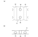
一方、尾筒9の筒壁には、冷却用の蒸気(流体)を流通させるための冷却溝(流体流通溝)13が軸線方向(ガス流通方向)に沿って形成されている。図2(b)に示すように、この冷却溝13は略半円形状を呈しており、図2(a)に示されるように、周方向に互いに間隔をあけて複数形成されている。そして、この冷却溝13には、図示しないボイラーから蒸気が供給・流通されて尾筒9を冷却する構成になっている。
【0026】
また、この尾筒9の筒壁には、燃焼領域11の近傍、すなわち火炎の近傍に位置して複数の吸音孔14が形成されている。これら吸音孔14は、図2(a)、(b)に示すように、冷却溝13と離間するように冷却溝13の間に間隔をあけて形成されている。さらに、尾筒9の外周には、燃焼領域11の近傍に位置して、尾筒9との間に空洞15を形成するダンパーとしての音響ライナ(共鳴器)16が全周に亙って環装されており、上記各吸音孔14はこの空洞15に開口するように形成されている。
【0027】
これら、吸音孔14の径(断面積)、音響ライナ16の大きさ(空洞15の容積)等の振動特性は、温度、圧力、燃焼ガスの流速、尾筒9の形状に応じて、予め求めた燃焼器固有の共鳴周波数に対応して設定されている。なお、これら吸音孔14および音響ライナ16の振動特性を音響的にチューニングすることで、各種燃焼器形状、燃焼条件に対応可能である。
【0028】
上記の構成のガスタービン燃焼器の作用について以下に説明する。
バーナ10の下流で燃料ガスが燃焼して燃焼振動が発生すると、燃焼振動による尾筒9内の空気振動(圧力波)が吸音孔14に捕捉されて共鳴する。これを詳述すると、吸音孔14内の空気と空洞15内の空気とは共鳴系を構成しており、空洞15内の空気はバネとして機能するため、この共鳴系の共鳴周波数の振動(音)に対して吸音孔14内の空気が激しく振動(共鳴)し、摩擦によってその周波数の音を吸収(吸音)することによって、燃焼振動の振幅が低下して減衰する。
【0029】
以上説明したように、本実施の形態のガスタービン燃焼器では、音響ライナ16と吸音孔14内の空気とが燃焼振動と共鳴するので、燃焼振動を低減または抑制させることができ、低NOx化の運転、および音響系との共振防止を両立することができる。特に、本実施の形態では、吸音孔14および音響ライナ16を燃焼領域11の火炎近傍に配置しているので、燃焼振動を効果的に吸音することができる。しかも、音響ライナ16を尾筒9の外周に全周に亙って環装しているので、尾筒9を介して燃焼振動が伝達されることを防止できる。そして、本実施の形態では、冷却溝13の間に吸音孔14を形成しているので、尾筒9に対する冷却に支障を来すことなく燃焼振動を抑制することができる。
【0030】
また、尾筒9における燃焼振動が起こり難くなることで、上記燃焼器を備えるガスタービンやジェットエンジンにおいては、燃焼振動に起因する燃焼器やケーシングの共振が防止され、その結果として安定した運転が実現できる。
【0031】
図3および図4は、本発明のガスタービン燃焼器の第2の実施の形態を示す図である。これらの図において、図1および図2に示す第1の実施の形態の構成要素と同一の要素については同一符号を付し、その説明を省略する。第2の実施の形態と上記の第1の実施の形態とが異なる点は、蒸気冷却ではなく空気冷却としたことである。
【0032】
また、図3に示すように、本実施の形態ではバーナ10および燃焼領域11が第1実施形態に比較して上流側に配置されており、この場合も吸音孔14および音響ライナ16は燃焼領域11の近傍に配置される。また、図4(a)に示すように、尾筒9には、ガス流通方向に沿って冷却溝13が周方向に間隔をあけて複数形成されており、尾筒9の外周面には冷却溝13と空洞15とを連通させる冷却孔17が冷却溝13の上流側に形成されている。そして、尾筒9の内周面には、尾筒内部と冷却溝13とを連通させる冷却孔19が冷却溝13の下流側に形成されている。そして、吸音孔14は、図4(b)に示すように冷却溝13の間で、且つ冷却孔17、19の間に形成されている。
【0033】
一方、図3に示すように、音響ライナ16には外部と空洞15とを連通する冷却孔18が複数形成されている。他の構成は、上記第1の実施の形態と同様である。
【0034】
本実施の形態のガスタービン燃焼器では、冷却用の空気は音響ライナ16の冷却孔18から空洞15に流入した後、冷却孔17から冷却溝13に導入される。そして、冷却用空気は、冷却孔19を介して尾筒9の内部に導入されるが、冷却溝13を流通する間に対流冷却により尾筒9を冷却する。
【0035】
このような冷却機構を有する燃焼器においても、上記第1の実施の形態と同様に音響ライナ16と吸音孔14内の空気とが燃焼振動と共鳴することで、燃焼振動を低減または抑制することができ、低NOx化の運転、および音響系との共振防止を両立することができる。
【0036】
図5は、本発明のガスタービン燃焼器の第3の実施の形態を示す図である。この図において、図1および図2に示す第1の実施の形態の構成要素と同一の要素については同一符号を付し、その説明を省略する。第2の実施の形態と上記の第1の実施の形態とが異なる点は、音響ライナ16に抵抗体を設けたことである。すなわち、図5に示すように、本実施の形態では音響ライナ16の空洞15にセルメット等の多孔質金属からなる吸音材21が抵抗体として装填される。
【0037】
従って、本実施の形態では、上記第1の実施の形態と同様の作用・効果が得られることに加えて、抵抗体を考慮した音響ライナ16の音響設計を行い、最適な抵抗体を選定することにより、吸音孔14での摩擦ロスに加え、抵抗体21での摩擦ロスを生ずることができ、さらに大きな燃焼振動低減効果を得ることができる。
【0038】
なお、ガスタービン燃焼器に抵抗体を設ける構成としては、上記第3の実施の形態に限定されるものではなく、図6に示すように、吸音孔14が形成された筒体9の外周に、焼結金網等の表面材22を抵抗体として環装してもよい。この構成でも上記第3の実施形態と同様の作用・効果が得られる。さらに、図7に示すように、抵抗体として音響ライナ16の空洞15に多孔質金属からなる吸音材21を装填し、且つ吸音孔14が形成された筒体9の外周に表面材22を環装しても同様の作用・効果を得ることができる。
【0039】
なお、上記実施の形態において、吸音孔14および音響ライナ16を尾筒9に設ける構成としたが、これに限定されるものではなく、燃焼領域11が内筒2の内部に位置する場合には、この内筒に設ければよい。また、上記実施の形態で例示した吸音孔14、冷却溝13、冷却孔17〜19の形状、配置は一例であり、他の形状、配置としてもよい。
【0040】
【発明の効果】
以上説明したように、請求項1に係るガスタービン燃焼器は、内部に燃焼領域を有する筒体を備え、前記筒体の外周に、空洞を有する共鳴器が環装され、前記筒体の筒壁に、前記筒体の外部から供給される冷却用の流体を流通できるように、周方向に互いに間隔をあけて前記筒壁の軸線方向に沿って前記共鳴器内を通過するように形成された複数の流体流通溝が設けられるとともに、これら流体流通溝の間に、前記空洞に開口する吸音孔が形成される構成となっている。
これにより、このガスタービン燃焼器では、燃焼振動を低減または抑制して、低NOx化の運転、および音響系との共振防止を両立できるという効果が得られる。
また、このガスタービン燃焼器では、筒体に対する冷却に支障を来すことなく燃焼振動を抑制できるという効果が得られる。
【0041】
請求項2に係るガスタービン燃焼器は、共鳴器および吸音孔が筒体の共鳴周波数に対応する振動特性を有する構成となっている。
これにより、このガスタービン燃焼器では、共鳴器および吸音孔内の空気が燃焼振動と共鳴することで燃焼振動を低減または抑制して、低NOx化の運転、および音響系との共振防止を両立できるという効果が得られる。
【0042】
請求項3に係るガスタービン燃焼器は、共鳴器および吸音孔が燃焼領域近傍に配置される構成となっている。
これにより、このガスタービン燃焼器では、焼振動を効果的に吸音できるという効果が得られる。
【0044】
請求項4に係るガスタービン燃焼器は、共鳴器の空洞に抵抗体が装填される構成となっている。
これにより、このガスタービン燃焼器では、吸音孔での摩擦ロスに加え、抵抗体での摩擦ロスを生ずることができ、さらに大きな燃焼振動低減効果を得ることができる。
【0045】
請求項5に係るガスタービン燃焼器は、吸音孔が形成された筒体の外周に抵抗体が環装される構成となっている。
これにより、このガスタービン燃焼器では、吸音孔での摩擦ロスに加え、抵抗体での摩擦ロスを生ずることができ、さらに大きな燃焼振動低減効果を得ることができる。
【0046】
請求項6に係るガスタービンは、請求項1から6のいずれかに記載のガスタービン燃焼器を有する構成となっている。構成となっている。
これにより、このガスタービンでは、燃焼振動に起因する燃焼器やガスタービンのケーシングの共振が防止され、その結果として安定した運転が実現できるという効果が得られる。
【0047】
請求項7に係るジェットエンジンは、請求項1から6のいずれかに記載のガスタービン燃焼器を有する構成となっている。
これにより、このジェットエンジンでは、燃焼振動に起因する燃焼器やエンジンのケーシングの共振が防止され、その結果として安定した運転が実現できるという効果が得られる。
【図面の簡単な説明】
【図1】 本発明の第1の実施の形態を示す図であって、尾筒に吸音孔および音響ライナが設けられた断面図である。
【図2】 同尾筒の(a)は平面図、(b)は断面図である。
【図3】 本発明の第2の実施の形態を示す図であって、尾筒に吸音孔および音響ライナが設けられた断面図である。
【図4】 同尾筒の(a)は平面図、(b)は断面図である。
【図5】 本発明の第3の実施の形態を示す図であって、音響ライナの空洞に抵抗体が装填された断面図である。
【図6】 本発明の別の実施形態を示す図であって、音響ライナの空洞に抵抗体が装填され、且つ吸音孔が形成された筒体の外周に抵抗体が環装された断面図である。
【図7】 本発明の別の実施形態を示す図であって、吸音孔が形成された筒体の外周に抵抗体が環装された断面図である。
【図8】 従来の燃焼器を示す要部断面図である。
【図9】 図8に示した燃焼器の縦断面図である。
【符号の説明】
2 内筒(筒体)
9 尾筒(筒体)
11 燃焼領域
13 冷却溝(流体流通溝)
14 吸音孔
15 空洞
16 音響ライナ(共鳴器)
21 吸音材(抵抗体)
22 表面材(抵抗体)[0001]
BACKGROUND OF THE INVENTION
The present invention relates to a gas turbine combustor capable of reducing combustion vibration, a gas turbine including the combustor, and a jet engine.
[0002]
[Prior art]
A gas turbine that extracts the shaft output to the outside by compressing the gas that becomes the working fluid with a compressor and heating it, and expanding the generated high-temperature high-pressure gas in the turbine, and the output in the form of kinetic energy of a high-speed jet In jet engines that are directly used for propulsion of aircraft, reduction of emissions such as nitrogen oxides (NOx) has been required due to recent environmental problems.
Such a gas turbine and a jet engine have a compressor, a combustor, and a turbine as main components, and the compressor and the turbine are directly connected to each other through a main shaft. A combustor is connected to the discharge port of the compressor, and the working fluid discharged from the compressor is heated to a predetermined turbine inlet temperature by the combustor. The high-temperature and high-pressure working fluid supplied to the turbine expands by passing between the stationary blade and the moving blade attached to the main shaft side in the casing, thereby rotating the main shaft and obtaining an output. In the case of a gas turbine, a shaft output obtained by subtracting the power consumed by the compressor can be obtained, so that it can be used as a drive source by connecting a generator or the like to the other end of the main shaft.
[0003]
By the way, in the above-described gas turbine and jet engine, various researches and developments relating to the combustor are underway in order to reduce emissions of NOx and the like. In a premixing type combustor, it is known that making the mixing ratio of fuel gas and air uniform is effective in reducing NOx. That is, when the mixing ratio is not uniform, a local high temperature portion is generated in the flame in the high concentration region, so that a large amount of NOx is generated in this high temperature portion and the total discharge amount of the entire combustor increases.
As a conventional technique for solving such a non-uniform mixing ratio, for example, there is one described in Japanese Patent Laid-Open No. 11-141878. In this prior art, a gas turbine in which a rectifying plate provided with a large number of small holes is provided on the air inflow side of the combustor, and the air flow flowing into the combustor is rectified by the rectifying plate to make the mixing ratio uniform. A combustor is described.
[0004]
Hereinafter, as a prior art, this gas turbine combustor will be briefly described with reference to FIGS. 8 and 9. Here, reference numeral 1 in the figure denotes a combustor, 2 denotes an inner cylinder, 3 denotes a premixing nozzle, 4 denotes a pilot burner, 5 denotes a main burner, and 6 denotes a top hat. Is formed with an
As indicated by arrows in the figure, the air flow supplied from the compressor is reversed to approximately 180 degrees and flows into the inlet of the
Therefore, the air flow that has passed through the rectifying
[0005]
[Problems to be solved by the invention]
However, the conventional gas turbine combustor, the gas turbine, and the jet engine as described above have the following problems.
Combustion of premixed gas of uniform concentration is advantageous in terms of reducing NOx, but the flame burns in a narrow and narrow range in a short time, so the amount of heat generated per unit space increases and combustion oscillation occurs. The problem that it is easy to occur.
Such combustion vibration propagates as a pressure wave, and in some cases, it will resonate with an acoustic system comprising a casing such as a combustor and a gas turbine, which may increase internal pressure fluctuations as combustion vibration. Under such conditions, normal operation of gas turbines, jet engines, etc. is difficult.
In addition to this, since the turbulence of the air flow leaving the compressor is large and the turbulence is not attenuated so much, the turbulence during combustion tends to be too strong and the combustion tends to become unstable. Even if such combustion instability occurs, a pressure wave of internal pressure fluctuation is generated in the combustor, so that this pressure wave propagates and, in some cases, resonates with an acoustic system comprising a casing such as a combustor and a gas turbine. It will be. Therefore, internal pressure fluctuations as combustion vibrations may increase, and normal operation of gas turbines, jet engines, and the like is difficult under such conditions.
[0006]
The present invention has been made in consideration of the above points, and reduces combustion vibration while maintaining low NOx in a gas turbine combustor, thereby enabling stable operation in a gas turbine or a jet engine. For the purpose.
[0007]
[Means for Solving the Problems]
In order to achieve the above object, the present invention employs the following configuration.
The gas turbine combustor according to claim 1 includes a cylindrical body having a combustion region therein, a resonator having a cavity is provided around the outer periphery of the cylindrical body, and the cylindrical body is provided on a cylindrical wall of the cylindrical body. A plurality of fluid flow grooves formed so as to pass through the resonator along the axial direction of the cylindrical wall at intervals in the circumferential direction so that a cooling fluid supplied from the outside of the tube can flow. And a sound absorbing hole that opens into the cavity is formed between the fluid circulation grooves.
[0008]
Therefore, in the gas turbine combustor of the present invention, the air oscillated by the combustion vibration resonates with the sound absorption holes and the air in the cavity. Therefore, the pressure fluctuation caused by the combustion vibration can be suppressed by attenuating the combustion vibration and reducing its amplitude.
Further, in the gas turbine combustor of the present invention, combustion vibration can be suppressed even when the cylinder is cooled by the flow of fluid.
[0009]
The gas turbine combustor according to
[0010]
Therefore, in the gas turbine combustor of the present invention, combustion vibration generated in the cylinder can be effectively suppressed.
[0011]
The gas turbine combustor according to claim 3 is the gas turbine combustor according to
[0012]
Therefore, in the gas turbine combustor of the present invention, the pressure fluctuation can be more effectively suppressed by suppressing the vibration in the vicinity of the combustion region where the combustion vibration is larger.
[0015]
A gas turbine combustor according to a fourth aspect is the gas turbine combustor according to any one of the first to third aspects, wherein a resistor is loaded in a cavity of the resonator. A gas turbine combustor according to a sixth aspect is the gas turbine combustor according to any one of the first to fifth aspects, wherein a resistor is provided around an outer periphery of the cylindrical body in which the sound absorbing holes are formed. It is characterized by this.
[0016]
Therefore, in the gas turbine combustor of the present invention, the acoustic design of the resonator in consideration of the resistor is performed, and by selecting the optimum resistor, the friction loss at the resistor is reduced in addition to the friction loss at the sound absorption hole. It is possible to obtain a greater combustion vibration reduction effect.
[0017]
The gas turbine according to claim 6 is a compressor that compresses air and supplies the compressed air as an air stream, the gas turbine combustor according to any one of claims 1 to 5 , and a high temperature supplied from the gas turbine combustor. A turbine that outputs shaft output by expanding and rotating high-pressure gas.
[0018]
Therefore, in the gas turbine of the present invention, the combustion vibration can be reduced by employing the above-described combustor. Therefore, resonance of the acoustic system including the combustor and the gas turbine casing is prevented.
[0019]
According to a seventh aspect of the present invention, there is provided a jet engine that compresses air and supplies the compressed air as an air stream, the gas turbine combustor according to any one of the first to fifth aspects, and high-temperature and high-pressure gas from the gas turbine combustor. And a turbine to be supplied.
[0020]
Therefore, in the jet engine of the present invention, the combustion vibration can be reduced by employing the above-described combustor. Therefore, resonance of the acoustic system composed of the combustor and the engine casing is prevented.
[0021]
DETAILED DESCRIPTION OF THE INVENTION
Hereinafter, a first embodiment of a gas turbine combustor, a gas turbine, and a jet engine according to the present invention will be described.
As described in the prior art, each of the gas turbine and the jet engine includes a compressor, a combustor, and a turbine as main components. One gas turbine expands a high-temperature and high-pressure gas in the turbine to rotate a main shaft, and uses the generated shaft output as a driving force for a generator or the like. A jet engine expands a high-temperature and high-pressure gas in a turbine to rotate a main shaft, and uses the kinetic energy of a high-speed jet (exhaust gas) injected from the turbine outlet as an aircraft propulsive force.
[0022]
Among the above-described components, the compressor introduces a gas serving as a working fluid, that is, air, compresses it, and supplies the compressed air to the combustor. As this compressor, an axial compressor directly connected to the turbine by a main shaft is used, and the air (atmosphere) sucked from the suction port is compressed and supplied to the combustor connected to the discharge port. This air stream burns fuel gas in the combustor, and the generated high-temperature and high-pressure gas is supplied to the turbine.
[0023]
Here, the gas turbine combustor is shown in FIGS. In these drawings, the same components as those in FIGS. 8 and 9 shown as the conventional example are denoted by the same reference numerals, and the description thereof will be simplified. In FIG. 1,
[0024]
A
[0025]
On the other hand, a cooling groove (fluid flow groove) 13 for flowing cooling steam (fluid) is formed in the tube wall of the
[0026]
A plurality of
[0027]
These vibration characteristics such as the diameter (cross-sectional area) of the
[0028]
The operation of the gas turbine combustor configured as described above will be described below.
When the fuel gas burns downstream of the
[0029]
As described above, in the gas turbine combustor of the present embodiment, the
[0030]
In addition, since the combustion vibration in the
[0031]
3 and 4 are views showing a second embodiment of the gas turbine combustor of the present invention. In these drawings, the same components as those of the first embodiment shown in FIGS. 1 and 2 are denoted by the same reference numerals, and the description thereof is omitted. The difference between the second embodiment and the first embodiment described above is that air cooling is used instead of steam cooling.
[0032]
Further, as shown in FIG. 3, in the present embodiment, the
[0033]
On the other hand, as shown in FIG. 3, the
[0034]
In the gas turbine combustor according to the present embodiment, the cooling air flows from the
[0035]
Even in the combustor having such a cooling mechanism, the
[0036]
FIG. 5 is a view showing a third embodiment of the gas turbine combustor of the present invention. In this figure, the same reference numerals are given to the same elements as those of the first embodiment shown in FIGS. 1 and 2, and the description thereof is omitted. The difference between the second embodiment and the first embodiment is that the
[0037]
Therefore, in this embodiment, in addition to obtaining the same operation and effect as those of the first embodiment, the acoustic design of the
[0038]
In addition, as a structure which provides a resistor in a gas turbine combustor, it is not limited to the said 3rd Embodiment, As shown in FIG. 6, in the outer periphery of the
[0039]
In the above embodiment, the
[0040]
【The invention's effect】
As described above, the gas turbine combustor according to claim 1 includes a cylinder having a combustion region therein, and a resonator having a cavity is provided around the outer periphery of the cylinder, and the cylinder of the cylinder is provided. It is formed so as to pass through the resonator along the axial direction of the cylindrical wall at intervals in the circumferential direction so that a cooling fluid supplied from the outside of the cylindrical body can flow through the wall. In addition, a plurality of fluid circulation grooves are provided, and a sound absorbing hole that opens to the cavity is formed between the fluid circulation grooves.
Thereby, in this gas turbine combustor, the effect of reducing or suppressing combustion vibration and achieving both NOx reduction operation and resonance prevention with the acoustic system can be obtained.
Further, in this gas turbine combustor, an effect that combustion vibration can be suppressed without hindering cooling of the cylindrical body is obtained.
[0041]
The gas turbine combustor according to
As a result, in this gas turbine combustor, the air in the resonator and the sound absorption hole resonates with the combustion vibration, thereby reducing or suppressing the combustion vibration, and achieving both low NOx operation and prevention of resonance with the acoustic system. The effect that it can be obtained.
[0042]
The gas turbine combustor according to claim 3 is configured such that the resonator and the sound absorption hole are disposed in the vicinity of the combustion region.
Thereby, in this gas turbine combustor, the effect that a burning vibration can be absorbed effectively is acquired.
[0044]
The gas turbine combustor according to
Thereby, in this gas turbine combustor, in addition to the friction loss at the sound absorption hole, it is possible to generate the friction loss at the resistor, and to obtain a greater combustion vibration reduction effect.
[0045]
The gas turbine combustor according to
Thereby, in this gas turbine combustor, in addition to the friction loss at the sound absorption hole, it is possible to generate the friction loss at the resistor, and to obtain a greater combustion vibration reduction effect.
[0046]
A gas turbine according to a sixth aspect includes the gas turbine combustor according to any one of the first to sixth aspects. It has a configuration.
Thereby, in this gas turbine, resonance of the combustor and the casing of the gas turbine due to combustion vibration is prevented, and as a result, an effect that stable operation can be realized is obtained.
[0047]
A jet engine according to a seventh aspect includes the gas turbine combustor according to any one of the first to sixth aspects.
Thus, in this jet engine, resonance of the combustor and the engine casing due to combustion vibration is prevented, and as a result, an effect that stable operation can be realized is obtained.
[Brief description of the drawings]
FIG. 1 is a cross-sectional view showing a first embodiment of the present invention, in which a sound absorbing hole and an acoustic liner are provided in a tail cylinder.
2A is a plan view and FIG. 2B is a cross-sectional view of the tail cylinder.
FIG. 3 is a cross-sectional view showing a second embodiment of the present invention, in which a sound absorbing hole and an acoustic liner are provided in a tail cylinder.
4A is a plan view and FIG. 4B is a cross-sectional view of the tail cylinder.
FIG. 5 is a cross-sectional view showing a third embodiment of the present invention, in which a resistor is loaded in a cavity of an acoustic liner.
FIG. 6 is a diagram showing another embodiment of the present invention, and is a cross-sectional view in which a resistor is loaded in a cavity of an acoustic liner and a resistor is mounted on the outer periphery of a cylindrical body in which a sound absorbing hole is formed. It is.
FIG. 7 is a view showing another embodiment of the present invention, and is a cross-sectional view in which a resistor is provided around the outer periphery of a cylindrical body in which sound absorbing holes are formed.
FIG. 8 is a cross-sectional view of a main part showing a conventional combustor.
9 is a longitudinal sectional view of the combustor shown in FIG.
[Explanation of symbols]
2 Inner cylinder (cylinder)
9 Tail tube (cylinder)
11
14
21 Sound absorbing material (resistor)
22 Surface material (resistor)
Claims (7)
前記筒体の外周に、空洞を有する共鳴器が環装され、前記筒体の筒壁に、前記筒体の外部から供給される冷却用の流体を流通できるように、周方向に互いに間隔をあけて前記筒壁の軸線方向に沿って前記共鳴器内を通過するように形成された複数の流体流通溝が設けられるとともに、これら流体流通溝の間に、前記空洞に開口する吸音孔が形成されることを特徴とするガスタービン燃焼器。Provided with a cylinder having a combustion region inside,
Resonators having cavities are mounted around the outer periphery of the cylinder, and are spaced apart from each other in the circumferential direction so that cooling fluid supplied from outside the cylinder can flow through the cylinder wall of the cylinder. A plurality of fluid circulation grooves formed so as to pass through the resonator along the axial direction of the cylindrical wall are provided, and a sound absorption hole that opens to the cavity is formed between the fluid circulation grooves A gas turbine combustor.
前記共鳴器および前記吸音孔は、前記筒体の共鳴周波数に対応する振動特性を有することを特徴とするガスタービン燃焼器。The gas turbine combustor according to claim 1.
The gas turbine combustor, wherein the resonator and the sound absorption hole have vibration characteristics corresponding to a resonance frequency of the cylindrical body.
前記共鳴器および前記吸音孔は、前記燃焼領域近傍に配置されていることを特徴とするガスタービン燃焼器。The gas turbine combustor according to claim 1 or 2,
The gas turbine combustor, wherein the resonator and the sound absorption hole are disposed in the vicinity of the combustion region.
前記共鳴器の空洞に抵抗体が装填されることを特徴とするガスタービン燃焼器。The gas turbine combustor according to any one of claims 1 to 3,
A gas turbine combustor, wherein a resistor is loaded in a cavity of the resonator.
前記吸音孔が形成された前記筒体の外周に抵抗体が環装されることを特徴とするガスタービン燃焼器。The gas turbine combustor according to any one of claims 1 to 4,
A gas turbine combustor, wherein a resistor is provided around an outer periphery of the cylindrical body in which the sound absorbing holes are formed.
Priority Applications (6)
| Application Number | Priority Date | Filing Date | Title |
|---|---|---|---|
| JP2000371312A JP3676228B2 (en) | 2000-12-06 | 2000-12-06 | Gas turbine combustor, gas turbine and jet engine |
| US10/001,804 US6640544B2 (en) | 2000-12-06 | 2001-12-05 | Gas turbine combustor, gas turbine, and jet engine |
| EP01128924A EP1213539B1 (en) | 2000-12-06 | 2001-12-05 | Gas turbine combustor, gas turbine, and jet engine |
| CA002364377A CA2364377C (en) | 2000-12-06 | 2001-12-05 | Gas turbine combustor, gas turbine, and jet engine |
| DE60105531T DE60105531T2 (en) | 2000-12-06 | 2001-12-05 | Gas turbine combustor, gas turbine and jet engine |
| US10/464,499 US6973790B2 (en) | 2000-12-06 | 2003-06-19 | Gas turbine combustor, gas turbine, and jet engine |
Applications Claiming Priority (1)
| Application Number | Priority Date | Filing Date | Title |
|---|---|---|---|
| JP2000371312A JP3676228B2 (en) | 2000-12-06 | 2000-12-06 | Gas turbine combustor, gas turbine and jet engine |
Publications (2)
| Publication Number | Publication Date |
|---|---|
| JP2002174427A JP2002174427A (en) | 2002-06-21 |
| JP3676228B2 true JP3676228B2 (en) | 2005-07-27 |
Family
ID=18841056
Family Applications (1)
| Application Number | Title | Priority Date | Filing Date |
|---|---|---|---|
| JP2000371312A Expired - Lifetime JP3676228B2 (en) | 2000-12-06 | 2000-12-06 | Gas turbine combustor, gas turbine and jet engine |
Country Status (5)
| Country | Link |
|---|---|
| US (1) | US6640544B2 (en) |
| EP (1) | EP1213539B1 (en) |
| JP (1) | JP3676228B2 (en) |
| CA (1) | CA2364377C (en) |
| DE (1) | DE60105531T2 (en) |
Cited By (1)
| Publication number | Priority date | Publication date | Assignee | Title |
|---|---|---|---|---|
| US11326780B2 (en) | 2017-03-24 | 2022-05-10 | Mitsubishi Power, Ltd. | Resonant sound absorbing device of gas turbine combustor, gas turbine combustor including the same, and gas turbine |
Families Citing this family (50)
| Publication number | Priority date | Publication date | Assignee | Title |
|---|---|---|---|---|
| US6973790B2 (en) * | 2000-12-06 | 2005-12-13 | Mitsubishi Heavy Industries, Ltd. | Gas turbine combustor, gas turbine, and jet engine |
| JP2002195565A (en) | 2000-12-26 | 2002-07-10 | Mitsubishi Heavy Ind Ltd | Gas turbine |
| ES2309029T3 (en) | 2001-01-09 | 2008-12-16 | Mitsubishi Heavy Industries, Ltd. | GAS TURBINE COMBUSTION CHAMBER. |
| JP3962554B2 (en) * | 2001-04-19 | 2007-08-22 | 三菱重工業株式会社 | Gas turbine combustor and gas turbine |
| GB2390150A (en) * | 2002-06-26 | 2003-12-31 | Alstom | Reheat combustion system for a gas turbine including an accoustic screen |
| US7832211B2 (en) | 2002-12-02 | 2010-11-16 | Mitsubishi Heavy Industries, Ltd. | Gas turbine combustor and a gas turbine equipped therewith |
| US6964170B2 (en) * | 2003-04-28 | 2005-11-15 | Pratt & Whitney Canada Corp. | Noise reducing combustor |
| JP2005076982A (en) | 2003-08-29 | 2005-03-24 | Mitsubishi Heavy Ind Ltd | Gas turbine combustor |
| JP4494889B2 (en) * | 2004-07-05 | 2010-06-30 | 三菱重工業株式会社 | Attenuation device |
| US7334408B2 (en) * | 2004-09-21 | 2008-02-26 | Siemens Aktiengesellschaft | Combustion chamber for a gas turbine with at least two resonator devices |
| GB0425794D0 (en) | 2004-11-24 | 2004-12-22 | Rolls Royce Plc | Acoustic damper |
| AR053113A1 (en) * | 2006-01-04 | 2007-04-25 | Juan G Kippes | STEAM ENGINE WITH BOILER BY CONVECTION. |
| US7628020B2 (en) * | 2006-05-26 | 2009-12-08 | Pratt & Whitney Canada Cororation | Combustor with improved swirl |
| US7856830B2 (en) * | 2006-05-26 | 2010-12-28 | Pratt & Whitney Canada Corp. | Noise reducing combustor |
| DE102006026969A1 (en) * | 2006-06-09 | 2007-12-13 | Rolls-Royce Deutschland Ltd & Co Kg | Gas turbine combustor wall for a lean-burn gas turbine combustor |
| JP4773904B2 (en) * | 2006-07-11 | 2011-09-14 | 三菱重工業株式会社 | Gas turbine combustor |
| US7788926B2 (en) * | 2006-08-18 | 2010-09-07 | Siemens Energy, Inc. | Resonator device at junction of combustor and combustion chamber |
| DE102006040760A1 (en) * | 2006-08-31 | 2008-03-06 | Rolls-Royce Deutschland Ltd & Co Kg | Lean-burning gas turbine combustion chamber wall, has Inflow holes formed perpendicularly over chamber wall, and damping openings formed by shingle, where shingle is spaced apart from chamber wall by using side part |
| DE102006053277B4 (en) * | 2006-11-03 | 2010-02-18 | Deutsches Zentrum für Luft- und Raumfahrt e.V. | Resonator device and combustion chamber device |
| JP5054988B2 (en) * | 2007-01-24 | 2012-10-24 | 三菱重工業株式会社 | Combustor |
| US20080245337A1 (en) * | 2007-04-03 | 2008-10-09 | Bandaru Ramarao V | System for reducing combustor dynamics |
| US7578369B2 (en) * | 2007-09-25 | 2009-08-25 | Hamilton Sundstrand Corporation | Mixed-flow exhaust silencer assembly |
| EP2116770B1 (en) * | 2008-05-07 | 2013-12-04 | Siemens Aktiengesellschaft | Combustor dynamic attenuation and cooling arrangement |
| US20090311641A1 (en) * | 2008-06-13 | 2009-12-17 | Gunther Berthold | Gas flame stabilization method and apparatus |
| CN104033926B (en) | 2009-02-27 | 2019-04-16 | 三菱日立电力系统株式会社 | Burner and the gas turbine for having the burner |
| US9267443B2 (en) | 2009-05-08 | 2016-02-23 | Gas Turbine Efficiency Sweden Ab | Automated tuning of gas turbine combustion systems |
| US9354618B2 (en) | 2009-05-08 | 2016-05-31 | Gas Turbine Efficiency Sweden Ab | Automated tuning of multiple fuel gas turbine combustion systems |
| US9671797B2 (en) | 2009-05-08 | 2017-06-06 | Gas Turbine Efficiency Sweden Ab | Optimization of gas turbine combustion systems low load performance on simple cycle and heat recovery steam generator applications |
| US8437941B2 (en) | 2009-05-08 | 2013-05-07 | Gas Turbine Efficiency Sweden Ab | Automated tuning of gas turbine combustion systems |
| RU2508506C2 (en) * | 2009-09-01 | 2014-02-27 | Дженерал Электрик Компани | Method and unit for fluid feed in gas turbine engine combustion chamber |
| EP2302302A1 (en) * | 2009-09-23 | 2011-03-30 | Siemens Aktiengesellschaft | Helmholtz resonator for a gas turbine combustion chamber |
| EP2362147B1 (en) * | 2010-02-22 | 2012-12-26 | Alstom Technology Ltd | Combustion device for a gas turbine |
| EP2385303A1 (en) | 2010-05-03 | 2011-11-09 | Alstom Technology Ltd | Combustion Device for a Gas Turbine |
| US9546558B2 (en) | 2010-07-08 | 2017-01-17 | Siemens Energy, Inc. | Damping resonator with impingement cooling |
| EP2690365B1 (en) * | 2011-03-22 | 2015-12-30 | Mitsubishi Heavy Industries, Ltd. | Acoustic damper, combustor, and gas turbine |
| JP5804808B2 (en) | 2011-07-07 | 2015-11-04 | 三菱日立パワーシステムズ株式会社 | Gas turbine combustor and its combustion vibration damping method |
| EP2559945A1 (en) * | 2011-08-17 | 2013-02-20 | Siemens Aktiengesellschaft | Combustion arrangement and turbine comprising a damping facility |
| US9249977B2 (en) | 2011-11-22 | 2016-02-02 | Mitsubishi Hitachi Power Systems, Ltd. | Combustor with acoustic liner |
| EP2642203A1 (en) * | 2012-03-20 | 2013-09-25 | Alstom Technology Ltd | Annular Helmholtz damper |
| EP2642204A1 (en) * | 2012-03-21 | 2013-09-25 | Alstom Technology Ltd | Simultaneous broadband damping at multiple locations in a combustion chamber |
| US9447971B2 (en) * | 2012-05-02 | 2016-09-20 | General Electric Company | Acoustic resonator located at flow sleeve of gas turbine combustor |
| US9400108B2 (en) | 2013-05-14 | 2016-07-26 | Siemens Aktiengesellschaft | Acoustic damping system for a combustor of a gas turbine engine |
| US9410484B2 (en) * | 2013-07-19 | 2016-08-09 | Siemens Aktiengesellschaft | Cooling chamber for upstream weld of damping resonator on turbine component |
| JP6302238B2 (en) * | 2013-12-20 | 2018-03-28 | 三菱重工業株式会社 | Exhaust device and gas turbine |
| JP6229232B2 (en) * | 2014-03-31 | 2017-11-15 | 三菱日立パワーシステムズ株式会社 | Combustor, gas turbine including the same, and repair method for combustor |
| WO2016032434A1 (en) * | 2014-08-26 | 2016-03-03 | Siemens Energy, Inc. | Film cooling hole arrangement for acoustic resonators in gas turbine engines |
| JP5913503B2 (en) * | 2014-09-19 | 2016-04-27 | 三菱重工業株式会社 | Combustion burner and combustor, and gas turbine |
| US10260643B2 (en) | 2014-12-02 | 2019-04-16 | United Technologies Corporation | Bleed valve resonator drain |
| CN113803296A (en) * | 2020-06-16 | 2021-12-17 | 中国航发商用航空发动机有限责任公司 | Aircraft engine, acoustic lining pore plate and manufacturing method of acoustic lining pore plate |
| CN115076729B (en) * | 2021-03-12 | 2023-09-26 | 中国航发商用航空发动机有限责任公司 | Combustion chamber and verification method for sound absorption effect of combustion chamber |
Family Cites Families (6)
| Publication number | Priority date | Publication date | Assignee | Title |
|---|---|---|---|---|
| GB1496163A (en) | 1974-08-16 | 1977-12-30 | Foseco Int | Burner quarls |
| JPH06173711A (en) * | 1992-12-09 | 1994-06-21 | Mitsubishi Heavy Ind Ltd | Tail cylinder of combustor |
| DE59709276D1 (en) | 1997-07-15 | 2003-03-13 | Alstom Switzerland Ltd | Vibration damping combustion chamber wall structure |
| JP3592912B2 (en) * | 1997-11-13 | 2004-11-24 | 三菱重工業株式会社 | Gas turbine combustor |
| DE59809097D1 (en) * | 1998-09-30 | 2003-08-28 | Alstom Switzerland Ltd | Combustion chamber for a gas turbine |
| US6530221B1 (en) * | 2000-09-21 | 2003-03-11 | Siemens Westinghouse Power Corporation | Modular resonators for suppressing combustion instabilities in gas turbine power plants |
-
2000
- 2000-12-06 JP JP2000371312A patent/JP3676228B2/en not_active Expired - Lifetime
-
2001
- 2001-12-05 CA CA002364377A patent/CA2364377C/en not_active Expired - Lifetime
- 2001-12-05 DE DE60105531T patent/DE60105531T2/en not_active Revoked
- 2001-12-05 US US10/001,804 patent/US6640544B2/en not_active Expired - Lifetime
- 2001-12-05 EP EP01128924A patent/EP1213539B1/en not_active Revoked
Cited By (1)
| Publication number | Priority date | Publication date | Assignee | Title |
|---|---|---|---|---|
| US11326780B2 (en) | 2017-03-24 | 2022-05-10 | Mitsubishi Power, Ltd. | Resonant sound absorbing device of gas turbine combustor, gas turbine combustor including the same, and gas turbine |
Also Published As
| Publication number | Publication date |
|---|---|
| JP2002174427A (en) | 2002-06-21 |
| DE60105531D1 (en) | 2004-10-21 |
| CA2364377C (en) | 2007-03-27 |
| EP1213539A1 (en) | 2002-06-12 |
| EP1213539B1 (en) | 2004-09-15 |
| US6640544B2 (en) | 2003-11-04 |
| US20020066272A1 (en) | 2002-06-06 |
| DE60105531T2 (en) | 2005-11-10 |
| CA2364377A1 (en) | 2002-06-06 |
Similar Documents
| Publication | Publication Date | Title |
|---|---|---|
| JP3676228B2 (en) | Gas turbine combustor, gas turbine and jet engine | |
| US6973790B2 (en) | Gas turbine combustor, gas turbine, and jet engine | |
| JP6059902B2 (en) | Sound damping device used in gas turbine engine | |
| JP3999644B2 (en) | Gas turbine combustor and gas turbine provided with the same | |
| JP5709401B2 (en) | Injector with integral resonator | |
| EP2587153B1 (en) | Fuel nozzle assembly for use in turbine engines and methods of assembling same | |
| CN105431684B (en) | Cooling cover piece for gas turbine damped resonator | |
| JP5112926B2 (en) | System for reducing combustor dynamics | |
| JP4429730B2 (en) | gas turbine | |
| KR101201559B1 (en) | Damping device and gas turbine combustor | |
| JP2002039533A (en) | Combustor, gas turbine, and jet engine | |
| JP6243621B2 (en) | Acoustic resonator located in the flow sleeve of a gas turbine combustor | |
| TW200413675A (en) | Gas turbine combustor, and gas turbine with the combustor | |
| JP5080815B2 (en) | Exhaust duct flow splitter system | |
| RU2661440C2 (en) | System (options) and method for damping dynamic processes in combustion chamber | |
| JP2006242050A (en) | Blade cooling structure for gas turbine | |
| WO2013043078A1 (en) | Combustor cap for damping low frequency dynamics | |
| RU2739659C2 (en) | Sound-absorbing nozzle (versions) | |
| US8631654B2 (en) | Burner system and method for damping such a burner system | |
| KR102068305B1 (en) | Combustor, and gas turbine including the same | |
| JP3999645B2 (en) | gas turbine | |
| JP3999646B2 (en) | Gas turbine combustor and gas turbine provided with the same | |
| JP6640581B2 (en) | Acoustic dampers, combustors and gas turbines | |
| JP5054988B2 (en) | Combustor | |
| JP7324381B1 (en) | Combustor cylinder, combustor and gas turbine |
Legal Events
| Date | Code | Title | Description |
|---|---|---|---|
| A977 | Report on retrieval |
Free format text: JAPANESE INTERMEDIATE CODE: A971007 Effective date: 20040715 |
|
| A131 | Notification of reasons for refusal |
Free format text: JAPANESE INTERMEDIATE CODE: A131 Effective date: 20040720 |
|
| A521 | Request for written amendment filed |
Free format text: JAPANESE INTERMEDIATE CODE: A523 Effective date: 20040902 |
|
| A02 | Decision of refusal |
Free format text: JAPANESE INTERMEDIATE CODE: A02 Effective date: 20041207 |
|
| A521 | Request for written amendment filed |
Free format text: JAPANESE INTERMEDIATE CODE: A523 Effective date: 20050204 |
|
| A521 | Request for written amendment filed |
Free format text: JAPANESE INTERMEDIATE CODE: A523 Effective date: 20050214 |
|
| A911 | Transfer to examiner for re-examination before appeal (zenchi) |
Free format text: JAPANESE INTERMEDIATE CODE: A911 Effective date: 20050217 |
|
| TRDD | Decision of grant or rejection written | ||
| A01 | Written decision to grant a patent or to grant a registration (utility model) |
Free format text: JAPANESE INTERMEDIATE CODE: A01 Effective date: 20050405 |
|
| A61 | First payment of annual fees (during grant procedure) |
Free format text: JAPANESE INTERMEDIATE CODE: A61 Effective date: 20050427 |
|
| R151 | Written notification of patent or utility model registration |
Ref document number: 3676228 Country of ref document: JP Free format text: JAPANESE INTERMEDIATE CODE: R151 |
|
| FPAY | Renewal fee payment (event date is renewal date of database) |
Free format text: PAYMENT UNTIL: 20090513 Year of fee payment: 4 |
|
| FPAY | Renewal fee payment (event date is renewal date of database) |
Free format text: PAYMENT UNTIL: 20090513 Year of fee payment: 4 |
|
| FPAY | Renewal fee payment (event date is renewal date of database) |
Free format text: PAYMENT UNTIL: 20100513 Year of fee payment: 5 |
|
| FPAY | Renewal fee payment (event date is renewal date of database) |
Free format text: PAYMENT UNTIL: 20100513 Year of fee payment: 5 |
|
| FPAY | Renewal fee payment (event date is renewal date of database) |
Free format text: PAYMENT UNTIL: 20110513 Year of fee payment: 6 |
|
| FPAY | Renewal fee payment (event date is renewal date of database) |
Free format text: PAYMENT UNTIL: 20120513 Year of fee payment: 7 |
|
| FPAY | Renewal fee payment (event date is renewal date of database) |
Free format text: PAYMENT UNTIL: 20130513 Year of fee payment: 8 |
|
| FPAY | Renewal fee payment (event date is renewal date of database) |
Free format text: PAYMENT UNTIL: 20140513 Year of fee payment: 9 |
|
| S111 | Request for change of ownership or part of ownership |
Free format text: JAPANESE INTERMEDIATE CODE: R313111 |
|
| R350 | Written notification of registration of transfer |
Free format text: JAPANESE INTERMEDIATE CODE: R350 |
|
| R250 | Receipt of annual fees |
Free format text: JAPANESE INTERMEDIATE CODE: R250 |
|
| EXPY | Cancellation because of completion of term |