JP3999645B2 - gas turbine - Google Patents
gas turbine Download PDFInfo
- Publication number
- JP3999645B2 JP3999645B2 JP2002349753A JP2002349753A JP3999645B2 JP 3999645 B2 JP3999645 B2 JP 3999645B2 JP 2002349753 A JP2002349753 A JP 2002349753A JP 2002349753 A JP2002349753 A JP 2002349753A JP 3999645 B2 JP3999645 B2 JP 3999645B2
- Authority
- JP
- Japan
- Prior art keywords
- throat
- gas turbine
- annular tube
- combustion
- resistor
- Prior art date
- Legal status (The legal status is an assumption and is not a legal conclusion. Google has not performed a legal analysis and makes no representation as to the accuracy of the status listed.)
- Expired - Lifetime
Links
Images


Description
【0001】
【発明の属する技術分野】
本発明は、ガスタービン燃焼器(以下「燃焼器」と記すことがある)、及びこれを備えたガスタービンに関し、特に、低NOx(窒素酸化物)化を実現すべく燃焼振動を低減するガスタービン燃焼器、及びガスタービンに関する。
【0002】
【従来の技術】
従来よりガスタービンは、空気圧縮機(以下「圧縮機」と記すことがある)、燃焼器、及びタービンを主な構成要素とし、互いに主軸で直結された圧縮機とタービンの間に燃焼器が配設されてなり、作動流体となる空気が主軸の回転により圧縮機に吸入されて圧縮され、その圧縮空気が燃焼器に導入されて燃料とともに燃焼し、その高温高圧の燃焼ガスがタービンに吐出されてタービンとともに主軸を回転駆動させる。このようなガスタービンは、主軸の前端に発電機等を接続することでその駆動源として活用され、また、タービンの前方に燃焼ガス噴射用の排気口を配設することでジェットエンジンとして活用される。
【0003】
ところで、近年、法規制の根幹の1つをなす環境問題に対し、ガスタービンから排出される排気ガス中の特にNOxの低減化が強く望まれてきている。そのため、NOxを実際に生成する燃焼器には、特にNOxの生成を抑える技術が要求され、これを達成すべく燃焼器に採用される燃焼方式として、燃料と圧縮空気を予め混合させた後に燃焼させるという予混合燃焼方式が主流となっている。この予混合燃焼方式では、燃料が圧縮空気中に均一かつ希薄の状態で分散することから、燃焼火炎温度の局部的な上昇を防止でき、これにより、燃焼火炎温度の上昇に伴って増加するNOxの生成量を低減することが可能となるわけである。
【0004】
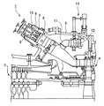
ここで、予混合燃焼方式の燃焼器を適用した従来より一般的なガスタービンについて、図8を参照しながら説明する。このガスタービン1は、大きくは、圧縮機2、ガスタービン燃焼器3、及びタービン4から構成されている。燃焼器3は、圧縮機2とタービン4の間に形成された空洞を有する車室5に取り付けられており、燃焼領域を有する内筒6、この内筒6の前端に連結された尾筒7、内筒6と同心状に配設された外筒8、内筒6の軸線上に後端から配設されたパイロットノズル9、このパイロットノズル9の周囲に円周方向で等間隔に配設された複数のメインノズル10、尾筒7の側壁に連結され車室5に開口するバイパスダクト11、このバイパスダクト11に配設されたバイパス弁12、このバイパス弁12の開閉度合いを調整するバイパス弁可変機構13より構成される。
【0005】
このような構成のもと、圧縮機2で圧縮された圧縮空気は、車室5内に流入し(図中の白抜き矢印)、内筒6の外周面と外筒8の内周面とで形成される管状空間を経た後ほぼ180度反転して(図中の実線矢印)、内筒6内に後端側から導入される。次いで、パイロットノズル9の前端のパイロットバーナ(不図示)に燃料が噴射されて拡散燃焼するとともに、各メインノズル10の前端のメインバーナ(不図示)に噴射された燃料と混合して予混合燃焼し、高温高圧の燃焼ガスとなる。この燃焼ガスは、尾筒7内を経由してその前端から吐出され、タービン4を駆動させる。なお、バイパスダクト11から尾筒7内へ、車室5内の圧縮空気の一部(以下「バイパス空気」と記すことがある)が供給されるが、これは、燃焼ガス濃度を調整する役割を果たす。
【0006】
【特許文献1】
特開2001−254634号公報
【特許文献2】
特開2002−174427号公報
【0007】
【発明が解決しようとする課題】
しかし、上記の予混合燃焼方式は一見低NOx化に対して優れるが、火炎が薄く狭い範囲で短時間に燃焼するため、単位空間当たりの燃焼エネルギが過大となり、燃焼振動が生じ易いという問題がある。この燃焼振動は、燃焼エネルギの一部が振動エネルギに変換されて発生するものであって、圧力波として伝播して燃焼器及びガスタービン等のケーシングからなる音響系と共鳴する場合、著しい振動や騒音を引き起こすだけでなく、燃焼器内に圧力変動や発熱変動を誘発させて燃焼状態が不安定になり、結果として低NOx化を阻害してしまう。
【0008】
このような燃焼振動の問題に対して、従来は、実際にガスタービンを運転させながら、正常な状態で稼動するよう適宜調整しつつ正規の運転条件を随時設定していた。そのため、煩雑な調整作業が不可欠であった。
【0009】
そこで、本発明は、上記の問題に鑑みてなされたものであり、低NOx化を安定的に実現すべく、燃焼振動の低減が可能なガスタービンを提供することを目的とするものである。
【0010】
【課題を解決するための手段】
上記目的を達成するため、本発明によるガスタービンは、互いに主軸で直結された空気圧縮機及びタービンと、これら空気圧縮機とタービンの間で前記主軸に対して同一円周上に配設され、各々内部に燃焼領域を有する筒体よりなる複数のガスタービン燃焼器と、を備えたガスタービンにおいて、前記主軸と同軸状で前記各筒体における後端の外側にあって車室の外部に配設された第1の環状管体と、各一端が前記各燃焼領域よりも上流域に開口するとともに、各他端が前記第1の環状管体内に開口する所定長さの第1のスロートと、を備え、前記各第1のスロートにおける前記各一端に多数の貫通孔を有する第1の抵抗体が挿嵌されている。これにより、燃焼領域で生じた燃焼振動の振動要素である流体粒子は、各第1の抵抗体に有効に捕捉されるとともに、各第1のスロートで連結された第1の環状管体内の空気と共鳴して、各第1の抵抗体付近で振動し、その振幅が減衰される。こうして燃焼振動が低減される。なお、各第1のスロートの各一端が開口する対象は、各筒体を構成する各内筒、或いは各内筒と同心状に配設された各外筒である。
【0014】
ここで、各燃焼器から各第1のスロートを経て連結された第1の環状管体の内部空間は、連続した1つの空間であることから、その内部空間そのもので圧力変動の位相差が生じる場合がある。この場合、各第1の抵抗体付近で流体粒子が十分振動しなくなるため、このままでは燃焼振動を十分に低減させることができなくなる。そこで、第1の環状管体内での圧力変動の位相差の発生を抑止して、各第1の抵抗体付近で流体粒子を有効に振動させる観点から、前記第1の環状管体内における前記各第1のスロートの前記各他端相互の間にそれぞれ第1の隔壁を設けることが好ましい。これにより、第1の環状管体内は第1のスロート毎すなわち燃焼器毎に分割され、圧力変動の位相差の発生が抑えられる。
【0015】
また、燃焼振動を効率よく低減させるには、流体粒子を多くの個所で振動させることが望ましく、これを達成するために、前記主軸と同軸状で前記第1の環状管体の外側にあって車室の外部に少なくとも1つ連設された第2の環状管体と、前記各第1のスロートに対応するとともに、相互に隣接する前記第1、第2の環状管体内にそれぞれ開口する所定長さの第2のスロートと、を備え、前記各第2のスロートにおいて前記第1の環状管体側に位置する各一端に多数の貫通孔を有する第2の抵抗体が挿嵌されているとよい。これにより流体粒子は、各第1の抵抗体付近での振動に加えて、各第2のスロートで連結された第2の環状管体内の空気と共鳴して、各第2の抵抗体付近で振動し、その振幅が減衰される。
【0016】
ここで、上記と同様に、第2の環状管体内での圧力変動の位相差の発生を抑止して、各第2の抵抗体付近で流体粒子を有効に振動させる観点から、前記第2の環状管体内における前記各第2のスロートの前記各他端相互の間にそれぞれ第2の隔壁を設けることが好ましい。
【0017】
【発明の実施の形態】
以下に、本発明の実施形態について図面を参照しながら詳述する。先ず、本発明の第1実施形態について説明する。図1は本発明の第1実施形態であるガスタービンの燃焼器付近を模式的に示す要部縦断面図である。なお、図中で図8と同じ名称で同じ機能を果たす部分には同一の符号を付し、重複する説明は省略する。後述する第2〜6実施形態においても同様とする。
【0018】
本実施形態の燃焼器3は、図8に示すようなガスタービン1に適用されるものと基本的な構成は同じであるが、以下の点で異なる。つまり、図1に示すように、外筒8の後端壁の外側に箱体50が配設されており、この箱体50内の空洞によって所定容積の内部空間が形成されている。また、箱体50は、所定長さを有する管状のスロート51を介して外筒8の後端壁に連結されていて、このスロート51は、一端51aが外筒8内すなわち燃焼領域よりも上流域に開口するとともに、他端51bが箱体50の内部空間に開口している。
【0019】
更に、スロート51の一端51aには、多数の貫通孔を有する抵抗体52が挿嵌されている。この抵抗体52は、例えば、パンチングメタル、セラミック焼結金属、焼結金網である。
【0020】
このような構成のもと、内筒6内の燃焼領域で生じた燃焼振動に関しては、その振動要素である流体粒子が、内筒6を経由して外筒8内に伝播し、次いで抵抗体52に有効に捕捉される。そして、スロート51で連結された箱体50の内部空間の空気と共鳴して、抵抗体52付近で振動する。この振動により、流体粒子の振幅が減衰され、その燃焼振動が低減されていく。その結果、安定的な低NOx化を実現できる。
【0021】
なお、図中の白抜き矢印は、圧縮機2で圧縮された圧縮空気の流れを示しており、圧縮空気は、先ず車室5内に流入し、次いで内筒6の外周面と外筒8の内周面とで形成される管状空間を経た後ほぼ180度反転して、内筒6内に後端側から導入される。そして、内筒6内で燃料とともに拡散燃焼及び予混合燃焼し、これにより生じた燃焼ガスが、尾筒7内を経由してその前端からタービン4に向けて吐出される。
【0022】
次に、本発明の第2実施形態について、図2を参照しながら説明する。本第2実施形態の特徴は、第1実施形態における箱体50の構造の簡素化を図った点にある。これは、箱体50の内部空間は大気圧よりも遥かに高圧な状態になるが、図1に示すように、箱体50そのものが燃焼器3の外部すなわち大気圧下に配設された場合、箱体50の内外で著しい圧力差が生じるため、箱体50にはその圧力差に耐え得る耐圧構造が欠かせず、そうすると、箱体50が必要以上に大型化するおそれがあるからである。
【0023】
そこで、本実施形態では、箱体50が車室5内に配設されている。なお、その際スロート51は、折曲して車室5のケーシングを嵌通することで足りる。これにより、箱体50そのものはその内部空間とほぼ等しい圧力下の車室5内におかれるため、内外の圧力差はほとんど生じない。従って、箱体50に格別な耐圧構造は全く不要となり、箱体50が必要以上に大型化することもない。
【0024】
次に、本発明の第3実施形態について、図3を参照しながら説明する。本第3実施形態の特徴は、第1、2実施形態におけるスロート51の一端51aの開口対象を変更した点にある。
【0025】
つまり、図3に示すように、スロート51の一端51aは、内筒6の側壁のうちで燃焼領域よりも上流域の部分から内筒6内に開口している。なお、図3では第2実施形態(図2参照)に準拠し、箱体50が車室5内に配設されたものに対して変更しているが、勿論第1実施形態(図1参照)に準拠したものに対して変更しても構わない。この場合、スロート51は、外筒8の後端壁又は側壁を嵌通して内筒6の側壁に連結されることで足りる。
【0026】
このような構成でも、上記した第1、2実施形態と同様に、流体粒子は、箱体50の内部空間の空気と共鳴して、抵抗体52付近で振動し、その振幅が減衰される。
【0027】
なお、スロート51の一端51aの開口対象が、外筒8の側壁であっても構わない。
【0028】
次に、本発明の第4実施形態について、図4、5を参照しながら説明する。本第4実施形態の特徴は、ガスタービン全体としての実用性を考慮しつつ、燃焼振動の低減を図った点にある。
【0029】
本実施形態の特徴部分の説明に先立ち、1つのガスタービンにおける燃焼器の一般的な配設位置について述べておく。図4、5に示すように、ガスタービン1には、主として効率よくタービン4に回転力を与える目的から、複数の燃焼器3が配設される。具体的には、各燃焼器3は、空気圧縮機2及びタービン4を直結する主軸Jに対して同一円周上に等角度間隔で配設されている(図5では、60度ピッチで6つ)。
【0030】
以下に本実施形態の特徴部分について説明する。主軸Jと同軸状で環状の内部空間を有する第1の環状管体30が、各外筒8の後端壁の外側に位置するよう配設されている。また、第1の環状管体30は、所定長さを有する管状の第1のスロート31を介して各外筒8の後端壁にそれぞれ連結されていて、これら第1のスロート31は、各一端31aが各外筒8内すなわち燃焼領域よりも上流域に開口するとともに、各他端31bが第1の環状管体30内に開口している。
【0031】
更に、第1のスロート31の一端31aには、多数の貫通孔を有する第1の抵抗体32が挿嵌されている。これら第1の抵抗体32は、第1〜3実施形態における抵抗体52と同様に、例えば、パンチングメタル、セラミック焼結金属、焼結金網である。
【0032】
このような構成によれば、各内筒6内の燃焼領域で生じた燃焼振動の振動要素である流体粒子は、各第1の抵抗体32に有効に捕捉されるとともに、各第1のスロート31で連結された第1の環状管体30内の空気と共鳴して、各第1の抵抗体32付近で振動する。この振動により、各燃焼器3における流体粒子の振幅が減衰され、その燃焼振動が低減されていく。その結果、ガスタービン全体として安定的な低NOx化を実現でき、これにより、排気ガス中のNOxの低減化を達成できる。
【0033】
次に、本発明の第5実施形態について、図6を参照しながら説明する。本第5実施形態の特徴は、第4実施形態における各第1の抵抗体32付近で流体粒子をより有効に振動させるように図った点にある。これは、第4実施形態における第1の環状管体30の内部空間が連続した1つの空間であることから、その内部空間そのもので圧力変動の位相差が生じる場合があり、この場合、各第1の抵抗体32付近で流体粒子が十分振動しなくなるため、このままでは燃焼振動を十分に低減させることができなくなるからである。
【0034】
そこで、本実施形態では、図6に示すように、第1の環状管体30内における各第1のスロート31の各他端31b相互の間に、それぞれ第1の隔壁35が設けられている。
【0035】
このようにすると、連続した1つの空間であった第1の環状管体30の内部空間は、第1のスロート31毎すなわち燃焼器3毎に第1の隔壁35により分割され、これら個々の分割空間での圧力変動の位相差の発生が抑えられる。従って、各第1の抵抗体32付近で流体粒子が有効に十分振動するため、燃焼振動を十分に低減できる。
【0036】
最後に、本発明の第6実施形態について、図7を参照しながら説明する。本第6実施形態の特徴は、第4、5実施形態における燃焼振動を効率よく低減させるように図った点にある。
【0037】
つまり、本実施形態では、図7に示すように、第1の環状管体30の外側に、これと同様に主軸Jと同軸状で環状の内部空間を有する第2の環状管体40が連設されている。また、第2の環状管体40は、所定長さを有し各第1のスロート31に対応した管状の第2のスロート41を介して、第1の環状管体30にそれぞれ連結されていて、これら第2のスロート41は、第1の環状管体30側に位置する各一端41aが第1の環状管体30内に開口するとともに、第2の環状管体40側に位置する各他端41bが第2の環状管体40内に開口している。
【0038】
更に、各第2のスロート41の各一端41aには、多数の貫通孔を有する第2の抵抗体42が挿嵌されている。これら第2の抵抗体42は、第1の抵抗体32と同様に、例えば、パンチングメタル、セラミック焼結金属、焼結金網である。
【0039】
このような構成によれば、流体粒子は、各第1の抵抗体32付近での振動に加えて、各第2のスロート41で連結された第2の環状管体40内の空気と共鳴して、各第2の抵抗体42付近で振動し、その振幅が減衰される。従って、流体粒子を多くの個所で振動させることが可能となり、燃焼振動を効率よく低減できることになる。
【0040】
なお、図7では、第1の環状管体30に対して第2の環状管体40が1つ連設されているが、2つ以上連設されても勿論構わない。この場合、隣接する第2の環状管体40同士をそれぞれ上記した第2のスロート41で連結することで足りる。
【0041】
また、第5実施形態と同様の趣旨から、第2の環状管体40内における各第2のスロート41の各他端41b相互の間にそれぞれ第2の隔壁(不図示)を設けてもよい。このようにすると、連続した1つの空間であった第2の環状管体40の内部空間は、第2のスロート41毎すなわち第1のスロート31を経由した燃焼器3毎に第2の隔壁により分割され、これら個々の分割空間での圧力変動の位相差の発生が抑えられる。従って、各第2の抵抗体42付近で流体粒子が有効に十分振動するため、各第1の抵抗体32付近での流体粒子の振動と相まって、燃焼振動をより十分に低減できる。
【0042】
更に、各第1のスロート31の一端31aの開口対象は、燃焼領域よりも上流域の部分である限り、内筒6の側壁や外筒8の側壁であっても構わない。
【0043】
その他本発明は上記の各実施形態に限定されず、本発明の趣旨を逸脱しない範囲で、種々の変更が可能である。例えば、スロート51や第1のスロート31や第2のスロート41の横断面形状は、円形に限らず多角形であっても構わない。
【0044】
【発明の効果】
以上説明した通り、本発明のガスタービンによれば、互いに主軸で直結された空気圧縮機及びタービンと、これら空気圧縮機とタービンの間で前記主軸に対して同一円周上に配設され、各々内部に燃焼領域を有する筒体よりなる複数のガスタービン燃焼器と、を備えたガスタービンにおいて、前記主軸と同軸状で前記各筒体における後端の外側にあって車室の外部に配設された第1の環状管体と、各一端が前記各燃焼領域よりも上流域に開口するとともに、各他端が前記第1の環状管体内に開口する所定長さの第1のスロートと、を備え、前記各第1のスロートにおける前記各一端に多数の貫通孔を有する第1の抵抗体が挿嵌されているので、燃焼領域で生じた燃焼振動の振動要素である流体粒子は、各第1の抵抗体に有効に捕捉されるとともに、各第1のスロートで連結された第1の環状管体内の空気と共鳴して、各第1の抵抗体付近で振動し、その振幅が減衰される。こうして燃焼振動を低減することが可能となり、ひいてはガスタービン全体として安定的な低NOx化を実現でき、これにより、排気ガス中のNOxの低減化を達成できる。
【0048】
ここで、前記第1の環状管体内における前記各第1のスロートの前記各他端相互の間にそれぞれ第1の隔壁を設けると、連続した1つの空間であった第1の環状管体の内部空間は、第1のスロート毎すなわち燃焼器毎に第1の隔壁により分割され、これら個々の分割空間での圧力変動の位相差の発生が抑えられる。従って、各第1の抵抗体付近で流体粒子が有効に十分振動するため、燃焼振動を十分に低減できる。
【0049】
また、前記主軸と同軸状で前記第1の環状管体の外側にあって車室の外部に少なくとも1つ連設された第2の環状管体と、前記各第1のスロートに対応するとともに、相互に隣接する前記第1、第2の環状管体内にそれぞれ開口する所定長さの第2のスロートと、を備え、前記各第2のスロートにおいて前記第1の環状管体側に位置する各一端に多数の貫通孔を有する第2の抵抗体が挿嵌されていると、流体粒子は、各第1の抵抗体付近での振動に加えて、各第2のスロートで連結された第2の環状管体内の空気と共鳴して、各第2の抵抗体付近で振動し、その振幅が減衰される。従って、流体粒子を多くの個所で振動させることが可能となり、燃焼振動を効率よく低減できる。
【0050】
ここで、前記第2の環状管体内における前記各第2のスロートの前記各他端相互の間にそれぞれ第2の隔壁を設けると、連続した1つの空間であった第2の環状管体の内部空間は、第2のスロート毎すなわち第1のスロートを経由した燃焼器毎に第2の隔壁により分割され、これら個々の分割空間での圧力変動の位相差の発生が抑えられる。従って、上記と同様に、各第2の抵抗体付近で流体粒子が有効に十分振動するため、各第1の抵抗体付近での流体粒子の振動と相まって、燃焼振動をより十分に低減できる。
【図面の簡単な説明】
【図1】 本発明の第1実施形態であるガスタービンの燃焼器付近を模式的に示す要部縦断面図である。
【図2】 本発明の第2実施形態であるガスタービンの燃焼器付近を模式的に示す要部縦断面図である。
【図3】 本発明の第3実施形態であるガスタービンの燃焼器付近を模式的に示す要部縦断面図である。
【図4】 本発明の第4実施形態であるガスタービンの燃焼器付近を模式的に示す要部縦断面図である。
【図5】 第4実施形態のガスタービンの燃焼器付近を模式的に示す要部横断面図である。
【図6】 本発明の第5実施形態であるガスタービンの燃焼器付近を模式的に示す要部横断面図である。
【図7】 本発明の第6実施形態であるガスタービンの燃焼器付近を模式的に示す要部縦断面図である。
【図8】 一般的なガスタービンの燃焼器付近の要部縦断面図である。
【符号の説明】
1 ガスタービン
2 圧縮機
3 ガスタービン燃焼器
4 タービン
5 車室
6 内筒
7 尾筒
8 外筒
9 パイロットノズル
10 メインノズル
11 バイパスダクト
12 バイパス弁
13 バイパス弁可変機構
30 第1の環状管体
31 第1のスロート
31a 第1のスロートの一端
31b 第1のスロートの他端
32 第1の抵抗体
35 第1の隔壁
40 第2の環状管体
41 第2のスロート
41a 第2のスロートの一端
41b 第2のスロートの他端
42 第2の抵抗体
50 箱体
51 スロート
51a スロートの一端
51b スロートの他端
52 抵抗体
J ガスタービンの主軸[0001]
BACKGROUND OF THE INVENTION
The present invention relates to a gas turbine combustor (hereinafter also referred to as a “combustor”) and a gas turbine equipped with the gas turbine combustor, and in particular, a gas that reduces combustion vibration to achieve low NOx (nitrogen oxide). The present invention relates to a turbine combustor and a gas turbine.
[0002]
[Prior art]
Conventionally, a gas turbine has an air compressor (hereinafter sometimes referred to as a “compressor”), a combustor, and a turbine as main components, and the combustor is disposed between the compressor and the turbine that are directly connected to each other through a main shaft. Air that is a working fluid is sucked into the compressor by the rotation of the main shaft and compressed, the compressed air is introduced into the combustor and combusted with the fuel, and the high-temperature and high-pressure combustion gas is discharged to the turbine. Then, the main shaft is driven to rotate together with the turbine. Such a gas turbine is used as a driving source by connecting a generator or the like to the front end of the main shaft, and is used as a jet engine by disposing an exhaust port for injecting combustion gas in front of the turbine. The
[0003]
By the way, in recent years, reduction of NOx in exhaust gas exhausted from gas turbines has been strongly desired for environmental problems that are one of the foundations of legal regulations. For this reason, in particular, a combustor that actually generates NOx is required to have a technique for suppressing the generation of NOx. As a combustion method employed in the combustor to achieve this, combustion is performed after fuel and compressed air are mixed in advance. The premixed combustion method of making it become the mainstream. In this premixed combustion system, the fuel is dispersed in the compressed air in a uniform and lean state, so that a local increase in the combustion flame temperature can be prevented, thereby increasing the NOx that increases with an increase in the combustion flame temperature. Therefore, it becomes possible to reduce the production amount of.
[0004]
Here, a conventional gas turbine to which a premixed combustion type combustor is applied will be described with reference to FIG. The
[0005]
Under such a configuration, the compressed air compressed by the
[0006]
[Patent Document 1]
JP 2001-254634 A [Patent Document 2]
Japanese Patent Laid-Open No. 2002-174427
[Problems to be solved by the invention]
However, the above premixed combustion method is excellent in reducing NOx at first glance. However, since the flame is burned in a narrow and narrow range in a short time, the combustion energy per unit space becomes excessive and combustion vibration is likely to occur. is there. This combustion vibration is generated when a part of the combustion energy is converted into vibration energy, and is propagated as a pressure wave to resonate with an acoustic system including a casing such as a combustor and a gas turbine. In addition to causing noise, pressure fluctuations and heat generation fluctuations are induced in the combustor and the combustion state becomes unstable, resulting in inhibition of low NOx.
[0008]
In the past, with respect to such a problem of combustion vibration, normal operating conditions have been set as needed while appropriately adjusting the gas turbine to operate in a normal state while actually operating the gas turbine. Therefore, complicated adjustment work is indispensable.
[0009]
Therefore, the present invention has been made in view of the above problems, and an object of the present invention is to provide a gas turbine capable of reducing combustion vibration in order to stably achieve low NOx.
[0010]
[Means for Solving the Problems]
In order to achieve the above object, a gas turbine according to the present invention is arranged on the same circumference with respect to the main shaft between the air compressor and the turbine directly connected to each other by the main shaft, and between the air compressor and the turbine, A gas turbine comprising a plurality of gas turbine combustors each having a combustion body inside, and coaxial with the main shaft and outside the rear end of each cylinder and outside the vehicle compartment. A first annular tube provided, and a first throat having a predetermined length whose one end opens in an upstream region from each combustion region and each other end opens in the first annular tube. , And a first resistor having a large number of through holes is inserted into each end of the first throat . As a result, the fluid particles, which are the vibration elements of the combustion vibration generated in the combustion region, are effectively captured by the first resistors, and the air in the first annular tubes connected by the first throats. And oscillates in the vicinity of each first resistor, and its amplitude is attenuated. Thus, combustion vibration is reduced. In addition, the object which each one end of each 1st throat opens is each inner cylinder which comprises each cylinder, or each outer cylinder arrange | positioned concentrically with each inner cylinder .
[0014]
Here, since the internal space of the first annular tube connected from each combustor via each first throat is one continuous space, a phase difference of pressure fluctuation occurs in the internal space itself. There is a case. In this case, since the fluid particles do not vibrate sufficiently in the vicinity of each first resistor, the combustion vibration cannot be sufficiently reduced as it is. Therefore, from the viewpoint of suppressing the occurrence of the phase difference of the pressure fluctuation in the first annular tube and effectively vibrating the fluid particles in the vicinity of each first resistor, the respective components in the first annular tube. It is preferable to provide a first partition between the other ends of the first throat. Thus, the first annular tube is divided for each first throat, that is, for each combustor, and the occurrence of a phase difference of pressure fluctuation is suppressed.
[0015]
Further, in order to reduce combustion oscillation efficiency, desirably vibrating the fluid particles in many places, in order to achieve this, in the outer side of said first annular tube in the main shaft coaxial At least one second annular tube connected to the outside of the passenger compartment, and a predetermined opening corresponding to each of the first throats and opening into the first and second annular tubes adjacent to each other. A second throat having a length, and a second resistor having a plurality of through holes is inserted into each end located on the first annular tube side in each second throat. Good. As a result, the fluid particles resonate with the air in the second annular tube connected to each second throat in addition to the vibration near each first resistor, and near each second resistor. It vibrates and its amplitude is attenuated.
[0016]
Here, in the same manner as described above, from the viewpoint of effectively vibrating the fluid particles in the vicinity of each second resistor by suppressing the occurrence of the phase difference of the pressure fluctuation in the second annular tube, the second It is preferable to provide a second partition between the other ends of the second throats in the annular tube.
[0017]
DETAILED DESCRIPTION OF THE INVENTION
Hereinafter, embodiments of the present invention will be described in detail with reference to the drawings. First, a first embodiment of the present invention will be described. FIG. 1 is a longitudinal sectional view of an essential part schematically showing the vicinity of a combustor of a gas turbine according to a first embodiment of the present invention. In the figure, parts having the same names and performing the same functions as those in FIG. 8 are denoted by the same reference numerals, and redundant description is omitted. The same applies to the second to sixth embodiments described later.
[0018]
The
[0019]
Further, a
[0020]
With such a configuration, with respect to the combustion vibration generated in the combustion region in the
[0021]
In addition, the white arrow in a figure has shown the flow of the compressed air compressed with the
[0022]
Next, a second embodiment of the present invention will be described with reference to FIG. The feature of the second embodiment is that the structure of the
[0023]
Therefore, in the present embodiment, the
[0024]
Next, a third embodiment of the present invention will be described with reference to FIG. The feature of the third embodiment is that the object to be opened at one
[0025]
In other words, as shown in FIG. 3, one
[0026]
Even in such a configuration, as in the first and second embodiments, the fluid particles resonate with the air in the internal space of the
[0027]
Note that the opening target of the one
[0028]
Next, a fourth embodiment of the present invention will be described with reference to FIGS. The feature of the fourth embodiment is that combustion vibration is reduced while considering the practicality of the gas turbine as a whole.
[0029]
Prior to the description of the characteristic part of this embodiment, a general arrangement position of the combustor in one gas turbine will be described. As shown in FIGS. 4 and 5, the
[0030]
The characteristic part of this embodiment will be described below. A first
[0031]
Further, a
[0032]
According to such a configuration, fluid particles that are vibration elements of combustion vibration generated in the combustion region in each
[0033]
Next, a fifth embodiment of the present invention will be described with reference to FIG. The feature of the fifth embodiment is that the fluid particles are vibrated more effectively in the vicinity of the
[0034]
Therefore, in the present embodiment, as shown in FIG. 6,
[0035]
In this way, the internal space of the first
[0036]
Finally, a sixth embodiment of the present invention will be described with reference to FIG. The feature of the sixth embodiment is that the combustion vibration in the fourth and fifth embodiments is efficiently reduced.
[0037]
That is, in the present embodiment, as shown in FIG. 7, the second
[0038]
Furthermore, a
[0039]
According to such a configuration, the fluid particles resonate with the air in the second
[0040]
In FIG. 7, one second
[0041]
Further, for the same purpose as in the fifth embodiment, a second partition wall (not shown) may be provided between each
[0042]
Furthermore, the opening target of the one
[0043]
In addition, the present invention is not limited to the above embodiments, and various modifications can be made without departing from the spirit of the present invention. For example, the cross-sectional shape of the
[0044]
【The invention's effect】
As described above , according to the gas turbine of the present invention, the air compressor and the turbine directly connected to each other by the main shaft, and the air compressor and the turbine are arranged on the same circumference with respect to the main shaft, A gas turbine comprising a plurality of gas turbine combustors each having a combustion body inside, and coaxial with the main shaft and outside the rear end of each cylinder and outside the vehicle compartment. A first annular tube provided, and a first throat having a predetermined length whose one end opens in an upstream region from each combustion region and each other end opens in the first annular tube. The first resistor having a large number of through holes is inserted into each one end of each first throat, so that the fluid particles that are the vibration elements of the combustion vibration generated in the combustion region are When effectively captured by each first resistor To, and resonates with the air of the first annular pipe body connected at each of the first throat, and oscillates about the first resistor, its amplitude is attenuated. In this way, it is possible to reduce the combustion vibration, and as a result, it is possible to realize a stable reduction in NOx for the entire gas turbine , thereby achieving a reduction in NOx in the exhaust gas .
[0048]
Here, when a first partition is provided between the other ends of the first throats in the first annular tube, the first annular tube, which is one continuous space, is provided. The internal space is divided by the first partition wall for each first throat, that is, for each combustor, and generation of a phase difference of pressure fluctuation in each of the divided spaces is suppressed. Therefore, since the fluid particles effectively vibrate in the vicinity of each first resistor, the combustion vibration can be sufficiently reduced.
[0049]
And a second annular tube that is coaxial with the main shaft and is outside the first annular tube and connected to the outside of the passenger compartment, and corresponds to each of the first throats. A second throat having a predetermined length opening in each of the first and second annular tubes adjacent to each other, and each of the second throats positioned on the first annular tube side. When a second resistor having a large number of through-holes is inserted into one end, the fluid particles are coupled to each second throat in addition to vibration in the vicinity of each first resistor. Resonates with the air in the annular tube and vibrates in the vicinity of each second resistor, and the amplitude is attenuated. Accordingly, the fluid particles can be vibrated at many locations, and combustion vibration can be efficiently reduced.
[0050]
Here, when a second partition is provided between the other ends of the second throats in the second annular tube, the second annular tube, which is one continuous space, is provided. The internal space is divided by the second partition wall for each second throat, that is, for each combustor that passes through the first throat, and the occurrence of a phase difference of pressure fluctuations in each of the divided spaces is suppressed. Therefore, similarly to the above, since the fluid particles effectively vibrate in the vicinity of each second resistor, the combustion vibration can be more sufficiently reduced in combination with the vibration of the fluid particles in the vicinity of each first resistor.
[Brief description of the drawings]
FIG. 1 is a longitudinal sectional view of an essential part schematically showing the vicinity of a combustor of a gas turbine according to a first embodiment of the present invention.
FIG. 2 is a longitudinal sectional view of an essential part schematically showing the vicinity of a combustor of a gas turbine according to a second embodiment of the present invention.
FIG. 3 is a longitudinal sectional view of an essential part schematically showing the vicinity of a combustor of a gas turbine according to a third embodiment of the present invention.
FIG. 4 is a longitudinal sectional view of an essential part schematically showing the vicinity of a combustor of a gas turbine according to a fourth embodiment of the present invention.
FIG. 5 is a cross-sectional view of an essential part schematically showing the vicinity of a combustor of a gas turbine according to a fourth embodiment.
FIG. 6 is a main part cross-sectional view schematically showing the vicinity of a combustor of a gas turbine according to a fifth embodiment of the present invention.
FIG. 7 is an essential part longitudinal sectional view schematically showing the vicinity of a combustor of a gas turbine according to a sixth embodiment of the present invention.
FIG. 8 is a longitudinal sectional view of an essential part in the vicinity of a combustor of a general gas turbine.
[Explanation of symbols]
DESCRIPTION OF
Claims (4)
前記主軸と同軸状で前記各筒体における後端の外側にあって車室の外部に配設された第1の環状管体と、各一端が前記各燃焼領域よりも上流域に開口するとともに、各他端が前記第1の環状管体内に開口する所定長さの第1のスロートと、を備え、前記各第1のスロートにおける前記各一端に多数の貫通孔を有する第1の抵抗体が挿嵌されていることを特徴とするガスタービン。 A plurality of gases comprising an air compressor and a turbine directly connected to each other by a main shaft, and a cylindrical body disposed between the air compressor and the turbine on the same circumference with respect to the main shaft and each having a combustion region therein A gas turbine comprising a turbine combustor,
A first annular tube disposed coaxially with the main shaft and outside the rear end of each cylindrical body and disposed outside the vehicle compartment, and each end opening upstream of each combustion region A first throat having a predetermined length that opens at the other end into the first annular tube, and having a plurality of through holes at each end of the first throat. A gas turbine in which is inserted .
Priority Applications (5)
| Application Number | Priority Date | Filing Date | Title |
|---|---|---|---|
| JP2002349753A JP3999645B2 (en) | 2002-12-02 | 2002-12-02 | gas turbine |
| EP03812351.9A EP1568869B1 (en) | 2002-12-02 | 2003-11-28 | Gas turbine combustor, and gas turbine with the combustor |
| US10/525,004 US7832211B2 (en) | 2002-12-02 | 2003-11-28 | Gas turbine combustor and a gas turbine equipped therewith |
| PCT/JP2003/015298 WO2004051063A1 (en) | 2002-12-02 | 2003-11-28 | Gas turbine combustor, and gas turbine with the combustor |
| TW092133684A TWI247867B (en) | 2002-12-02 | 2003-12-01 | Gas turbine combustor, and gas turbine with the combustor |
Applications Claiming Priority (1)
| Application Number | Priority Date | Filing Date | Title |
|---|---|---|---|
| JP2002349753A JP3999645B2 (en) | 2002-12-02 | 2002-12-02 | gas turbine |
Publications (2)
| Publication Number | Publication Date |
|---|---|
| JP2004183944A JP2004183944A (en) | 2004-07-02 |
| JP3999645B2 true JP3999645B2 (en) | 2007-10-31 |
Family
ID=32752200
Family Applications (1)
| Application Number | Title | Priority Date | Filing Date |
|---|---|---|---|
| JP2002349753A Expired - Lifetime JP3999645B2 (en) | 2002-12-02 | 2002-12-02 | gas turbine |
Country Status (1)
| Country | Link |
|---|---|
| JP (1) | JP3999645B2 (en) |
Families Citing this family (6)
| Publication number | Priority date | Publication date | Assignee | Title |
|---|---|---|---|---|
| JP4754987B2 (en) * | 2005-02-22 | 2011-08-24 | 三菱重工業株式会社 | Damping device, combustor and gas turbine |
| JP5054988B2 (en) * | 2007-01-24 | 2012-10-24 | 三菱重工業株式会社 | Combustor |
| JP4929357B2 (en) | 2007-11-21 | 2012-05-09 | 三菱重工業株式会社 | Damping device and gas turbine combustor |
| EP2642204A1 (en) | 2012-03-21 | 2013-09-25 | Alstom Technology Ltd | Simultaneous broadband damping at multiple locations in a combustion chamber |
| JP7393262B2 (en) | 2020-03-23 | 2023-12-06 | 三菱重工業株式会社 | Combustor and gas turbine equipped with the same |
| JPWO2022255334A1 (en) * | 2021-05-31 | 2022-12-08 |
-
2002
- 2002-12-02 JP JP2002349753A patent/JP3999645B2/en not_active Expired - Lifetime
Also Published As
| Publication number | Publication date |
|---|---|
| JP2004183944A (en) | 2004-07-02 |
Similar Documents
| Publication | Publication Date | Title |
|---|---|---|
| JP3999644B2 (en) | Gas turbine combustor and gas turbine provided with the same | |
| US7832211B2 (en) | Gas turbine combustor and a gas turbine equipped therewith | |
| JP3676228B2 (en) | Gas turbine combustor, gas turbine and jet engine | |
| RU2568030C2 (en) | Damping device to reduce pulsation of combustion chamber | |
| JP5813169B2 (en) | Combustor and gas turbine | |
| JP4929357B2 (en) | Damping device and gas turbine combustor | |
| JP4406126B2 (en) | Apparatus and method for rich-quenched-lean (RQL) concept in a gas turbine engine combustor with trapped vortex cavity | |
| JP4511658B2 (en) | Damping device for damping sound wave vibration amplification for burner | |
| EP2474784A1 (en) | Combustion system for a gas turbine comprising a resonator | |
| JP2008267799A (en) | Method and device for facilitating reduction of combustor pressure drop | |
| JP4727548B2 (en) | Combustor | |
| JP5409959B2 (en) | Burner device and vibration damping method for this kind of burner | |
| US20140311156A1 (en) | Combustor cap for damping low frequency dynamics | |
| JP3999645B2 (en) | gas turbine | |
| JP4177727B2 (en) | Gas turbine combustor | |
| JP3999646B2 (en) | Gas turbine combustor and gas turbine provided with the same | |
| JP6640581B2 (en) | Acoustic dampers, combustors and gas turbines | |
| JPH1183017A (en) | Combustor for gas turbine | |
| JP5054988B2 (en) | Combustor | |
| JP2004183945A (en) | Gas turbine combustor and gas turbine equipped with the same | |
| KR102164619B1 (en) | Combuster and gas turbine having the same | |
| JP2003130351A (en) | Combustor, gas turbine and jet engine | |
| CN112178695A (en) | Damper, burner assembly comprising a damper and method of manufacturing a damper | |
| JP2020159323A (en) | Acoustic damper, combustor and gas turbine | |
| JP2013181744A (en) | Fuel nozzle assembly used in turbine engine and assembly method of the same |
Legal Events
| Date | Code | Title | Description |
|---|---|---|---|
| A621 | Written request for application examination |
Free format text: JAPANESE INTERMEDIATE CODE: A621 Effective date: 20040709 |
|
| A131 | Notification of reasons for refusal |
Free format text: JAPANESE INTERMEDIATE CODE: A131 Effective date: 20061212 |
|
| A521 | Request for written amendment filed |
Free format text: JAPANESE INTERMEDIATE CODE: A523 Effective date: 20070208 |
|
| TRDD | Decision of grant or rejection written | ||
| A01 | Written decision to grant a patent or to grant a registration (utility model) |
Free format text: JAPANESE INTERMEDIATE CODE: A01 Effective date: 20070717 |
|
| A61 | First payment of annual fees (during grant procedure) |
Free format text: JAPANESE INTERMEDIATE CODE: A61 Effective date: 20070809 |
|
| R151 | Written notification of patent or utility model registration |
Ref document number: 3999645 Country of ref document: JP Free format text: JAPANESE INTERMEDIATE CODE: R151 |
|
| FPAY | Renewal fee payment (event date is renewal date of database) |
Free format text: PAYMENT UNTIL: 20100817 Year of fee payment: 3 |
|
| FPAY | Renewal fee payment (event date is renewal date of database) |
Free format text: PAYMENT UNTIL: 20100817 Year of fee payment: 3 |
|
| FPAY | Renewal fee payment (event date is renewal date of database) |
Free format text: PAYMENT UNTIL: 20110817 Year of fee payment: 4 |
|
| FPAY | Renewal fee payment (event date is renewal date of database) |
Free format text: PAYMENT UNTIL: 20110817 Year of fee payment: 4 |
|
| FPAY | Renewal fee payment (event date is renewal date of database) |
Free format text: PAYMENT UNTIL: 20120817 Year of fee payment: 5 |
|
| FPAY | Renewal fee payment (event date is renewal date of database) |
Free format text: PAYMENT UNTIL: 20130817 Year of fee payment: 6 |
|
| S111 | Request for change of ownership or part of ownership |
Free format text: JAPANESE INTERMEDIATE CODE: R313111 |
|
| R350 | Written notification of registration of transfer |
Free format text: JAPANESE INTERMEDIATE CODE: R350 |
|
| R250 | Receipt of annual fees |
Free format text: JAPANESE INTERMEDIATE CODE: R250 |
|
| EXPY | Cancellation because of completion of term |