JP2013099354A5 - - Google Patents

Download PDF

Info

Publication number
JP2013099354A5
JP2013099354A5 JP2013016045A JP2013016045A JP2013099354A5 JP 2013099354 A5 JP2013099354 A5 JP 2013099354A5 JP 2013016045 A JP2013016045 A JP 2013016045A JP 2013016045 A JP2013016045 A JP 2013016045A JP 2013099354 A5 JP2013099354 A5 JP 2013099354A5
Authority
JP
Japan
Prior art keywords
input shaft
driving force
shaft
drive shaft
transmitted
Prior art date
Legal status (The legal status is an assumption and is not a legal conclusion. Google has not performed a legal analysis and makes no representation as to the accuracy of the status listed.)
Granted
Application number
JP2013016045A
Other languages
Japanese (ja)
Other versions
JP2013099354A (en
JP5492315B2 (en
Filing date
Publication date
Application filed filed Critical
Priority to JP2013016045A priority Critical patent/JP5492315B2/en
Priority claimed from JP2013016045A external-priority patent/JP5492315B2/en
Publication of JP2013099354A publication Critical patent/JP2013099354A/en
Publication of JP2013099354A5 publication Critical patent/JP2013099354A5/ja
Application granted granted Critical
Publication of JP5492315B2 publication Critical patent/JP5492315B2/en
Active legal-status Critical Current
Anticipated expiration legal-status Critical

Links

Images

Description

コンバインCombine

本発明は、扱胴を備えた脱穀装置とエンジンとを走行機体に搭載し、前記脱穀装置の前部に刈取り部を設けたコンバインに関する。 The present invention relates to a combine in which a threshing device including a handling cylinder and an engine are mounted on a traveling machine body and a cutting portion is provided at a front portion of the threshing device .

この種のコンバインとして、従来、例えば特許文献1に記載されたものがあった Conventionally, for example, this type of combine is described in Patent Document 1 .

特開2004−121123号公報(段落〔0028〕−〔0033〕、図6,7)JP 2004-121123 A (paragraphs [0028]-[0033], FIGS. 6 and 7)

本第1発明は、扱胴を備えた脱穀装置とエンジンとを走行機体に搭載し、前記脱穀装置の前部に刈取り部を設けたコンバインにおいて、
前記刈取り部に、刈取り穀稈を前記脱穀装置に供給するフィーダと、このフィーダを駆動する左右向きの刈取り入力軸とが設けられ、
前記エンジンからの駆動力が伝達される入力軸と、前記入力軸からの駆動力を前記扱胴に伝達する扱胴出力軸とが、前記脱穀装置の走行機体前方側に設けられ、
前記入力軸が走行機体左右向きに配置され、前記入力軸からの駆動力が前記刈取り入力軸に伝達されるよう構成され、
前記扱胴出力軸が走行機体前後向きに配置され、前記入力軸からの駆動力がベベルギヤ機構を介して前記扱胴出力軸に伝達されるよう構成されている。
In the first aspect of the present invention, the threshing device including the handling cylinder and the engine are mounted on the traveling machine body, and the harvester is provided at the front of the threshing device .
The mowing unit is provided with a feeder that supplies the threshing device to the threshing device, and a left and right mowing input shaft that drives the feeder,
An input shaft to which the driving force from the engine is transmitted, and a barrel output shaft that transmits the driving force from the input shaft to the barrel are provided on the front side of the traveling machine body of the threshing device,
The input shaft is arranged in the left-right direction of the traveling machine body, and the driving force from the input shaft is configured to be transmitted to the cutting input shaft.
The handling cylinder output shaft is disposed in the longitudinal direction of the traveling machine body, and the driving force from the input shaft is transmitted to the handling cylinder output shaft via a bevel gear mechanism.

本第2発明では、前記入力軸と前記扱胴出力軸とを装備する伝動ケースが、前記脱穀装置の走行機体前方側に設けられている。
本第3発明では、前記伝動ケースは、前記脱穀装置の前壁部に支持されている。
本第4発明では、前記エンジンからの駆動力が前記脱穀装置の唐箕駆動軸に伝達され、前記唐箕駆動軸からの駆動力が前記入力軸に伝達されるよう構成されている。
本第5発明では、前記唐箕駆動軸は、前記脱穀装置の左右一側から左右他側に亘るように構成され、
前記エンジンからの駆動力が前記唐箕駆動軸の左右一端部に伝達され、前記唐箕駆動軸からの駆動力が前記唐箕駆動軸の左右他端部から前記入力軸に伝達されるように構成されている。
本第6発明では、前記エンジンからの駆動力が前記唐箕駆動軸における前記エンジンの側に伝達されるよう構成されている。
本第7発明では、前記唐箕駆動軸からの駆動力が前記唐箕駆動軸における前記エンジンとは反対側から前記入力軸に伝達されるように構成されている。
本第8発明では、前記唐箕駆動軸からの駆動力を前記入力軸に伝達する動力伝達機構は、前記入力軸からの駆動力を前記刈取り入力軸に伝達する動力伝達機構よりも、機体横外側に配置されている。
本第9発明では、前記唐箕駆動軸からの駆動力が、脱穀後の穀粒を搬送する搬送装置に伝達されるよう構成されている。
本第10発明では、前記唐箕駆動軸からの駆動力を前記入力軸に伝達する動力伝達機構は、前記唐箕駆動軸からの駆動力を前記搬送装置に伝達する動力伝達機構よりも、機体横外側に配置されている。
本第11発明では、前記唐箕駆動軸からの駆動力を前記入力軸に伝達する動力伝達機構は、ベルト式の伝達機構で構成されている。
本第12発明では、正面視において、前記入力軸が前記刈取り入力軸よりも上方に配置されている。
本第13発明では、前記入力軸からの駆動力が前記刈取り入力軸に伝達される動力伝達経路に、前記入力軸からの駆動力を逆転可能な逆転機構が設けられている。
本第14発明では、前記入力軸と前記扱胴出力軸とを装備する伝動ケースが、前記脱穀装置の走行機体前方側に設けられ、
前記伝動ケースの走行機体左右方向での中間部に、前記扱胴出力軸が配置されている。
本第15発明では、前記入力軸と前記扱胴出力軸とを装備する伝動ケースが、前記脱穀装置の走行機体前方側に設けられ、
前記伝動ケースの走行機体左右方向での中間部に、前記べベルギヤ機構を収容する収容部が形成されている。
本第16発明では、前記収容部の前壁部が、前記伝動ケースのケース本体に、ボルトで着脱可能に構成されている。
In this 2nd invention, the transmission case equipped with the said input shaft and the said handling cylinder output shaft is provided in the traveling machine body front side of the said threshing apparatus.
In this 3rd invention, the said transmission case is supported by the front wall part of the said threshing apparatus.
In this 4th invention, the driving force from the said engine is transmitted to the red pepper drive shaft of the said threshing apparatus, and the driving force from the said red pepper drive shaft is transmitted to the said input shaft.
In the fifth aspect of the present invention, the Kara drive shaft is configured to extend from the left and right sides of the threshing device to the left and right sides,
The driving force from the engine is transmitted to the left and right end portions of the Kara drive shaft, and the driving force from the Kara drive shaft is transmitted from the left and right other end portions of the Kara drive shaft to the input shaft. Yes.
In the sixth aspect of the present invention, the driving force from the engine is transmitted to the engine side of the Karatsu drive shaft.
In the seventh aspect of the invention, the driving force from the red pepper drive shaft is transmitted to the input shaft from the opposite side of the red pepper drive shaft to the engine.
In the eighth aspect of the invention, the power transmission mechanism that transmits the driving force from the Karatsu drive shaft to the input shaft is more laterally outward than the power transmission mechanism that transmits the driving force from the input shaft to the cutting input shaft. Is arranged.
In this 9th invention, it is comprised so that the drive force from the said Kara drive shaft may be transmitted to the conveying apparatus which conveys the grain after threshing.
In the tenth aspect of the invention, the power transmission mechanism that transmits the driving force from the red pepper drive shaft to the input shaft is more laterally outer than the power transmission mechanism that transmits the driving force from the red pepper drive shaft to the transport device. Is arranged.
In the eleventh aspect of the invention, the power transmission mechanism that transmits the driving force from the Kara drive shaft to the input shaft is constituted by a belt-type transmission mechanism.
In the twelfth aspect of the invention, the input shaft is disposed above the cutting input shaft in a front view.
In the thirteenth invention, a reverse rotation mechanism capable of reversing the driving force from the input shaft is provided in a power transmission path through which the driving force from the input shaft is transmitted to the cutting input shaft.
In the fourteenth invention, a transmission case equipped with the input shaft and the barrel output shaft is provided on the front side of the traveling machine body of the threshing device,
The handling cylinder output shaft is disposed in an intermediate portion of the transmission case in the lateral direction of the traveling machine body.
In the fifteenth aspect of the present invention, a transmission case equipped with the input shaft and the barrel output shaft is provided on the front side of the traveling machine body of the threshing device,
An accommodating portion for accommodating the bevel gear mechanism is formed at an intermediate portion of the transmission case in the lateral direction of the traveling machine body.
In the 16th invention, the front wall part of the said accommodating part is comprised with the case main body of the said transmission case so that attachment or detachment is possible with a volt | bolt.

コンバインの全体側面図である。It is a whole side view of a combine. コンバインの全体平面図である。It is a whole top view of a combine. 伝動機構の線図である。It is a diagram of a transmission mechanism. 伝動ケース配設部と操作部の正面図である。It is a front view of a transmission case arrangement | positioning part and an operation part. チェーン伝動機構の側面図である。It is a side view of a chain transmission mechanism. 操作部の斜視図である。It is a perspective view of an operation part. 正転クラッチ操作具の入り位置への操作状態と、アクセル操作具の高速位置への操作状態と、逆転クラッチ操作具の切り位置への操作状態と、牽制機構および高速逆転牽制機構の作用状態とを示す側面図である。The operating state of the forward rotation clutch operating tool to the entering position, the operating state of the accelerator operating tool to the high speed position, the operating state of the reverse rotation clutch operating tool to the disengagement position, and the operating state of the check mechanism and the high speed reverse rotation check mechanism FIG. 正転クラッチ操作具の切り位置への操作状態と、アクセル操作具の低速位置への操作状態と、逆転クラッチ操作具の入り位置への操作状態と、牽制機構および高速逆転牽制機構の解除状態とを示す側面図である。The operating state of the forward clutch operating tool to the cut position, the operating state of the accelerator operating tool to the low speed position, the operating state of the reverse clutch operating tool to the entering position, the release state of the check mechanism and the high speed reverse check mechanism FIG. (イ)は、テンション輪体のチェーン緊張操作状態での側面図、(ロ)は、緊張規制体の作用状態を示す側面図である。(A) is a side view in the chain tension operation state of a tension ring body, (b) is a side view which shows the action state of a tension control body. チェーン緊張機構の断面図である。It is sectional drawing of a chain tension mechanism.

以下、本発明の実施例を図面に基づいて説明する。
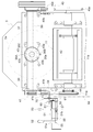
図1は、本発明の実施例に係るコンバインの全体側面図である。図2は、本発明の実施例に係るコンバインの全体平面図である。これらの図に示すように、本発明の実施例に係るコンバインは、左右一対のクローラ走行装置1,1によって自走するよう構成し、かつ運転座席2が装備された運転部3を有した自走機体を備え、この自走機体の機体フレーム4の後部側に自走機体横方向に並べて設けた脱穀装置5と穀粒袋詰め部6とを備え、前記脱穀装置5の前部にフィーダ11が連結された刈取り部10を備えている。このコンバインは、稲、麦などの穀粒を収穫するものであり、次の如く構成してある。
Embodiments of the present invention will be described below with reference to the drawings.
FIG. 1 is an overall side view of a combine according to an embodiment of the present invention. FIG. 2 is an overall plan view of the combine according to the embodiment of the present invention. As shown in these drawings, a combine according to an embodiment of the present invention is configured to be self-propelled by a pair of left and right crawler traveling devices 1 and 1 and has a driving unit 3 equipped with a driver seat 2. A threshing device 5 and a grain bagging unit 6 provided with a traveling machine body, arranged side by side in the lateral direction of the self-propelled machine body on the rear side of the machine body frame 4 of the self-propelled machine body, and a feeder 11 at the front part of the threshing device 5 are provided. Are connected to each other. This combine harvests grains such as rice and wheat and is configured as follows.

前記刈取り部10は、前記フィーダ11を備える他、このフィーダ11の前端部に前処理フレーム12が連結された前処理装置13を備えて構成してある。   In addition to the feeder 11, the mowing unit 10 includes a preprocessing device 13 in which a preprocessing frame 12 is connected to the front end of the feeder 11.

前記刈取り部10は、前記フィーダ11の脱穀装置5に対する上下揺動操作により、前処理フレーム12の下部に位置するプラットホーム14が地面付近に下降した下降作業状態と、前記プラットホーム14が地面から高く上昇した上昇非作業状態とに昇降する。刈取り部10を下降作業状態にして自走機体を走行させると、前記前処理装置13は、前処理フレーム12の前部に位置する左右一対のデバイダ15,15によって刈取り対象の植立穀稈と、非刈取り対象の植立穀稈とを分草し、刈取り対象の植立穀稈を刈取り装置16の上方に位置する回転リール17によって前処理フレーム12の後方側に掻き込みながらバリカン形の前記刈取り装置16によって刈取り処理し、刈取り穀稈を前記プラットホーム14の上面側に位置するオーガ18によってフィーダ11の前側に寄せ搬送し、フィーダ11の前側に位置した刈取り穀稈を前記オーガ18が一体回転自在に備えている掻き込み杆19によってフィーダ11の入り口(図示せず)に送り込む。フィーダ11は、これの内部に位置するフィーダコンベヤ11a(図3参照)によって前記掻き込み杆19からの刈取り穀稈をフィーダ11の後端部に搬送し、この後端部に位置する排出口(図示せず)から脱穀装置5の扱室(図示せず)に刈取り穀稈の株元から穂先までの全体を供給する。   The mowing unit 10 is in a descending work state in which the platform 14 located at the lower part of the pretreatment frame 12 is lowered near the ground by the vertical swinging operation of the feeder 11 with respect to the threshing device 5, and the platform 14 is raised above the ground. Ascend and descend to the raised non-working state. When the cutting unit 10 is moved down and the self-propelled machine body is driven, the pretreatment device 13 uses the pair of left and right dividers 15 and 15 located at the front part of the preprocessing frame 12 to establish the planted culm to be cut. The non-trimmed planted culm is weeded, and the clipper-shaped stalk is scraped into the rear side of the pretreatment frame 12 by the rotary reel 17 positioned above the trimming device 16. The reaping process is performed by the reaping device 16, and the reaped cereals are moved to the front side of the feeder 11 by the auger 18 located on the upper surface side of the platform 14, and the reaped cereals located on the front side of the feeder 11 are rotated integrally with the auger 18. It feeds into the entrance (not shown) of the feeder 11 with the scraping bar 19 provided freely. The feeder 11 conveys the harvested cereal from the raking culm 19 to the rear end of the feeder 11 by a feeder conveyor 11a (see FIG. 3) located inside the feeder 11, and a discharge port ( The whole from the root of the harvested cereal to the tip is supplied to the handling room (not shown) of the threshing device 5 from the not shown.

前記脱穀装置5は、扱室に供給された刈取り穀稈を走行機体前後向きの軸芯周りに回動する扱胴5a(図3参照)によって脱穀処理し、脱穀処理物を脱穀粒と排ワラとに選別処理し、脱穀粒を前記穀粒袋詰め部6の袋詰めタンク6aに供給する。   The threshing device 5 threshs the harvested cereal supplied to the handling room with a handling cylinder 5a (see FIG. 3) that rotates around the axis of the traveling machine in the front-rear direction. The threshing grains are supplied to the bagging tank 6a of the grain bagging unit 6.

図1,2に示すように、前記穀粒袋詰め部6は、前記袋詰めタンク6aを備える他、この袋詰めタンク6aの走行機体前後方向に並ぶ二つの穀粒吐出筒6bのそれぞれに対応させて袋詰めタンク6aの下方に設けた袋支持杆6cと、この袋支持杆6cの下方に配置して前記機体フレーム4に設けた袋受けデッキに兼用の作業デッキ6dと、前記機体フレーム4の横端部に支持された補助デッキ6eとを備えている。補助デッキ6eは、上下揺動自在に支持されており、機体フレーム4から走行機体横外側に水平に突出した下降使用姿勢と、この下降使用姿勢から上昇揺動して走行機体上下方向に沿った上昇格納姿勢とに切り換わる。   As shown in FIGS. 1 and 2, the grain bag filling unit 6 includes the bag filling tank 6 a and corresponds to each of two grain discharge cylinders 6 b arranged in the longitudinal direction of the traveling machine body of the bag filling tank 6 a. A bag support rod 6c provided below the bag filling tank 6a, a work deck 6d which is also disposed below the bag support rod 6c and provided on the machine frame 4 and serves as a bag receiving deck, and the machine frame 4 And an auxiliary deck 6e supported at the lateral end of the. The auxiliary deck 6e is supported so as to be swingable up and down, and is in a lowered use posture that protrudes horizontally from the machine body frame 4 to the lateral side of the traveling machine body, and rises and swings from the lowered use attitude along the vertical direction of the traveling machine body. Switch to the raised storage position.

前記自走機体は、前記運転座席2の下方に設けたエンジン20を備えている。図3は、前記エンジン20の駆動力を前記走行装置1と前記脱穀装置5と前記刈取り部10とに伝達する伝動機構の線図である。この図に示すように、前記伝動機構の走行伝動部は、前記エンジン20の出力軸20aの駆動力を、ベルト伝動機構21を介して走行変速装置22の入力軸22aに伝達し、この走行変速装置22の出力軸22bの駆動力を、走行ミッション23に入力してこの走行ミッション23によって前記左右一対の走行装置1,1に伝達する。   The self-propelled aircraft includes an engine 20 provided below the driver seat 2. FIG. 3 is a diagram of a transmission mechanism that transmits the driving force of the engine 20 to the traveling device 1, the threshing device 5, and the mowing unit 10. As shown in this figure, the traveling transmission portion of the transmission mechanism transmits the driving force of the output shaft 20a of the engine 20 to the input shaft 22a of the traveling transmission device 22 via the belt transmission mechanism 21, and this traveling shift is performed. The driving force of the output shaft 22 b of the device 22 is input to the traveling mission 23 and transmitted to the pair of left and right traveling devices 1, 1 through the traveling mission 23.

前記走行変速装置22は、前記走行ミッション23のケースに連設されている。この走行変速装置22は、前記入力軸22aをポンプ軸として備えた可変容量形でアキシャルプランジャ形の油圧ポンプと、この油圧ポンプからの圧油によって駆動されるアキシャルプランジャ形の油圧モータとを備えて構成されている。すなわち、走行変速装置22は、静油圧式無段変速装置になっている。   The travel transmission 22 is connected to the case of the travel mission 23. The travel transmission 22 includes a variable displacement axial plunger type hydraulic pump including the input shaft 22a as a pump shaft, and an axial plunger type hydraulic motor driven by pressure oil from the hydraulic pump. It is configured. That is, the travel transmission 22 is a hydrostatic continuously variable transmission.

前記伝動機構の作業伝動部は、前記エンジン20の出力軸20aをベルト伝動機構25を介して脱穀装置5の唐箕駆動軸26の一端側に連動させ、この唐箕駆動軸26の他端側をベルト伝動機構27(本発明に係る「唐箕駆動軸からの駆動力を搬送装置に伝達する動力伝達機構」に相当)を介して脱穀装置5の一番スクリューコンベヤ28(本発明に係る「搬送装置」に相当)と二番スクリューコンベヤ29(本発明に係る「搬送装置」に相当)とに連動させ、前記ベルト伝動機構27に設けた動力取り出し軸30をベルト伝動機構31を介して脱穀装置5の選別装置駆動軸32に連動させている。 The work transmission section of the transmission mechanism causes the output shaft 20a of the engine 20 to be linked to one end side of the tang drive shaft 26 of the threshing device 5 via the belt transmission mechanism 25, and the other end side of the tang drive shaft 26 is connected to the belt. The first screw conveyor 28 of the threshing device 5 (the “conveying device” according to the present invention ) via the transmission mechanism 27 (corresponding to “the power transmission mechanism for transmitting the driving force from the red pepper driving shaft to the conveying device” according to the present invention). considerably) and double-dip screw conveyor 29 (in conjunction with the with the equivalent) to the "conveying device" of the present invention, the belt transmission mechanism 27 threshing apparatus via the belt transmission mechanism 31 a power take-off shaft 30 which is provided on the 5 It is linked to the sorting device drive shaft 32.

前記伝動機構の作業伝動部は、前記エンジン20の前記出力軸20aから出力される駆動力を、前記ベルト伝動機構25と前記唐箕駆動軸26とこの唐箕駆動軸26の他端側に設けたベルト伝動機構35(本発明に係る「唐箕駆動軸からの駆動力を入力軸に伝達する動力伝達機構」に相当)とを介して伝動ケース36のケース入力軸37(本発明に係る「入力軸」に相当)に伝達し、このケース入力軸37の駆動力を伝動ケース36の脱穀出力軸38から扱胴5aに伝達し、前記ケース入力軸37の駆動力を、正回転クラッチ40(本発明に係る「入力軸からの駆動力を刈取り入力軸に伝達する動力伝達機構」に相当)を介して、あるいは、伝動ケース36の刈取り出力軸39と、逆回転クラッチ41(本発明に係る「逆転機構」に相当)とを介して刈取り部10の刈取り入力軸42に伝達する。この動力伝達についてさらに詳述すると、次の如く構成してある。 The work transmission unit of the transmission mechanism is configured to provide a driving force output from the output shaft 20a of the engine 20 to the belt transmission mechanism 25, the rotary drive shaft 26, and the other end side of the hot drive shaft 26. A case input shaft 37 of the transmission case 36 (an “input shaft” according to the present invention ) via a transmission mechanism 35 (corresponding to “a power transmission mechanism for transmitting the driving force from the Karatsu drive shaft to the input shaft” according to the present invention). transmitted to correspond) to, and transmits the driving force of the case the input shaft 37 from the threshing output shaft 38 of the transmission case 36 to the thresher 5a, the driving force of the case the input shaft 37, the forward rotation clutch 40 (the present invention according via the corresponding) to the "power transmission mechanism for transmitting the input shaft reaping the driving force from the input shaft", or, the output shaft 39 cutting of the transmission case 36, according to the reverse rotation clutch 41 (the present invention "reversing mechanism Equivalent to To the cutting input shaft 42 of the cutting unit 10. This power transmission will be described in further detail as follows.

すなわち、図2,4に示すように、前記伝動ケース36は、脱穀装置5の走行機体前方側で、かつ前記フィーダ11の後端部の上方に、脱穀装置5の前壁部に支持させて設けてある。図3に示すように、前記伝動ケース36は、前記扱胴出力軸38を伝動ケース36の走行機体横方向での中央部に走行機体前後向きに配置して備えている。前記伝動ケース36は、前記ケース入力軸37と前記刈取り出力軸39とを伝動ケース36の走行機体横方向での一端側と他端側とに分散した配置にして、かつ前記扱胴出力軸38を挟んで走行機体横方向に並んだ配置にして、さらにケース入力軸37も刈取り出力軸39も走行機体横向きになった配置にして備えている。前記扱胴出力軸38は、扱胴5aの回転支軸に一体回転自在に連結されている。   That is, as shown in FIGS. 2 and 4, the transmission case 36 is supported by the front wall portion of the threshing device 5 on the front side of the traveling machine body of the threshing device 5 and above the rear end portion of the feeder 11. It is provided. As shown in FIG. 3, the transmission case 36 includes the handling cylinder output shaft 38 arranged at the center of the transmission case 36 in the lateral direction of the traveling machine body in the longitudinal direction of the traveling machine body. The transmission case 36 has the case input shaft 37 and the cutting output shaft 39 distributed in one end side and the other end side in the lateral direction of the traveling body of the transmission case 36, and the cylinder output shaft 38. Further, the case input shaft 37 and the cutting output shaft 39 are arranged side by side in the horizontal direction of the traveling machine body. The handling cylinder output shaft 38 is connected to a rotating spindle of the handling cylinder 5a so as to be integrally rotatable.

前記伝動ケース36は、前記ケース入力軸37の端部に一体回転自在に設けたベベルギヤ43aを備えたベベルギヤ機構43を収容している。伝動ケース36の走行機体左右方向での中間部に、べベルギヤ機構43を収容する収容部36Aが形成されている。収容部36Aの前壁部36Bが、伝動ケース36のケース本体36Cに、ボルト36aで着脱可能に構成されている。このベベルギヤ機構43は、前記ベベルギヤ43aを備える他、前記刈取り出力軸39の端部に一体回転自在に設けたベベルギヤ43bと、前記ベベルギヤ43aと43bとに噛み合った状態で前記扱胴出力軸38に一体回転自在に設けたベベルギヤ43cとを備えて構成してある。つまり、ベベルギヤ機構43は、走行機体横向きのケース入力軸37と走行機体前後向きの脱穀出力軸38との連動を可能にし、かつケース入力軸37の回転方向と刈取り出力軸39の回転方向とが逆の回転方向になる状態でケース入力軸37と刈取り出力軸39とを連動させている。 The transmission case 36 accommodates a bevel gear mechanism 43 having a bevel gear 43 a provided at the end of the case input shaft 37 so as to be integrally rotatable. An accommodating portion 36A for accommodating the bevel gear mechanism 43 is formed in an intermediate portion of the transmission case 36 in the left-right direction of the traveling machine body. The front wall portion 36B of the housing portion 36A is configured to be detachable from the case main body 36C of the transmission case 36 with a bolt 36a. The bevel gear mechanism 43 includes the bevel gear 43a, a bevel gear 43b provided integrally with an end of the cutting output shaft 39, and a bevel gear 43a meshed with the bevel gears 43a and 43b. A bevel gear 43c provided so as to be integrally rotatable is provided. In other words, the bevel gear mechanism 43 enables the traveling machine body sideways case input shaft 37 and the traveling machine body front and rear threshing output shaft 38 to be linked, and the rotation direction of the case input shaft 37 and the rotation direction of the cutting output shaft 39 are The case input shaft 37 and the cutting output shaft 39 are interlocked with each other in the reverse rotational direction.

図3,4に示すように、前記正回転クラッチ40は、前記ケース入力軸37と前記刈取り入力軸42の一端側とに巻回された伝動ベルト40aがテンション部材40bのテンション輪体40cによって張り状態と緩み状態とに切り換え操作されることで入り状態と切り状態とに切り換わるようベルトテンションクラッチになっている。テンション部材40は、前記伝動ケース36の端部に揺動自在に支持されている。この正回転クラッチ40は、入り状態に切り換え操作されることにより、ケース入力軸37の駆動力を刈取り入力軸42に刈取り部10を正回転方向に駆動する駆動力として伝達する。   As shown in FIGS. 3 and 4, in the forward rotation clutch 40, a transmission belt 40a wound around the case input shaft 37 and one end of the cutting input shaft 42 is stretched by a tension ring body 40c of a tension member 40b. The belt tension clutch is switched to the on state and the off state by switching between the state and the loose state. The tension member 40 is swingably supported at the end of the transmission case 36. When the forward rotation clutch 40 is switched to the on state, the driving force of the case input shaft 37 is transmitted to the cutting input shaft 42 as the driving force for driving the cutting portion 10 in the forward rotation direction.

図3,4に示すように、前記逆回転クラッチ41は、前記刈取り出力軸39と前記刈取り入力軸42の他端側とに巻回された伝動ベルト41aがテンション部材41bのテンション輪体41cによって緊張状態と弛緩状態とに切り換え操作されることで入り状態と切り状態とに切り換わるようベルトテンションクラッチになっている。テンション部材41bは、前記伝動ケース36の端部に揺動自在に支持されている。この逆回転クラッチ41は、入り状態に切り換え操作されることにより、刈取り出力軸39の駆動力を刈取り入力軸42に刈取り部10を逆回転方向に駆動する駆動力として伝達する。   As shown in FIGS. 3 and 4, the reverse rotation clutch 41 includes a transmission belt 41a wound around the cutting output shaft 39 and the other end of the cutting input shaft 42 by a tension ring body 41c of a tension member 41b. The belt tension clutch is switched to the on state and the off state by switching between the tension state and the relaxed state. The tension member 41b is swingably supported at the end of the transmission case 36. When the reverse rotation clutch 41 is switched to the engaged state, the driving force of the cutting output shaft 39 is transmitted to the cutting input shaft 42 as the driving force for driving the cutting unit 10 in the reverse rotation direction.

図3に示すように、前記刈取り入力軸42は、前記フィーダコンベヤ11aを駆動するコンベヤ駆動軸になっている。前記刈取り入力軸42は、伝動チェーン44を介して刈取り装置16の駆動軸45に連動されている。この駆動軸45と、前記オーガ18の駆動軸46とが伝動チェーン47によって連動されている。オーガ18の駆動軸46と、回転リール17の駆動軸48とが、伝動チェーン49と伝動ベルト50とを利用した連動機構によって連動されている。   As shown in FIG. 3, the cutting input shaft 42 is a conveyor drive shaft that drives the feeder conveyor 11a. The cutting input shaft 42 is linked to the drive shaft 45 of the cutting device 16 via a transmission chain 44. The drive shaft 45 and the drive shaft 46 of the auger 18 are interlocked by a transmission chain 47. The drive shaft 46 of the auger 18 and the drive shaft 48 of the rotary reel 17 are interlocked by an interlocking mechanism using a transmission chain 49 and a transmission belt 50.

刈取り入力軸42は、正回転方向の駆動力が伝達されると、刈取り部10のフィーダコンベア11aとオーガ18と刈取り装置16と回転リール17とを通常の前処理作業や搬送作業を行うよう正回転方向に駆動し、逆回転方向の駆動力が伝達されると、刈取り部10のフィーダコンベア11aとオーガ18と刈取り装置16と回転リール17とを通常の作業用回転方向とは逆の回転方向に駆動する。   When the driving force in the forward rotation direction is transmitted, the reaping input shaft 42 forwards the feeder conveyor 11a, the auger 18, the reaping device 16, and the rotating reel 17 of the reaping unit 10 so as to perform normal preprocessing work and transport work. When driven in the rotation direction and the driving force in the reverse rotation direction is transmitted, the feeder conveyor 11a, the auger 18, the mowing device 16, and the rotary reel 17 of the cutting unit 10 are rotated in the direction opposite to the normal rotation direction for work. To drive.

図4は、前記正回転クラッチ40と前記逆回転クラッチ41との切り換え操作、および前記エンジン20の調速操作を行うよう前記運転部3に設けた操作部の正面視での構造を示している。図6は、前記操作部の斜視図である。これらの図と図2とに示すように、前記操作部は、前記運転座席2の横側方に設けた操作盤51と、この操作盤51に走行機体横方向に並べて設けたレバー形の正転クラッチ操作具52とレバー形のアクセル操作具53と、前記操作盤51の運転座席側とは反対側の横外側に設けたレバー形の逆転クラッチ操作具54とを備えている。   FIG. 4 shows a structure in a front view of an operation unit provided in the operation unit 3 so as to perform a switching operation between the forward rotation clutch 40 and the reverse rotation clutch 41 and a speed control operation of the engine 20. . FIG. 6 is a perspective view of the operation unit. As shown in FIG. 2 and FIG. 2, the operation unit includes an operation panel 51 provided on the lateral side of the driver's seat 2 and a lever-shaped right side panel provided on the operation panel 51 in the lateral direction of the traveling machine body. A rolling clutch operating tool 52, a lever-type accelerator operating tool 53, and a lever-type reverse clutch operating tool 54 provided on the laterally outer side opposite to the driver seat side of the operation panel 51 are provided.

前記正転クラッチ操作具52は、この操作具52の基部に一体回転自在に連結した回転支軸55を介して支持部材56に支持されており、前記回転支軸55の走行機体横向き軸芯のまわりに揺動する。前記支持部材56は、操作盤51の裏面側に取り付けられている。この正転クラッチ操作具52は、前記回転支軸55の正転クラッチ操作具52が連結している側とは反対側の端部に一体回転自在に設けた揺動アーム61を備えた連動機構60により、正回転クラッチ40のテンション部材40bに連動されている。   The forward rotation clutch operating tool 52 is supported by a support member 56 via a rotation support shaft 55 that is connected to the base of the operation tool 52 so as to be integrally rotatable. Swing around. The support member 56 is attached to the back side of the operation panel 51. The forward rotation clutch operating tool 52 includes an oscillating arm 61 provided with an oscillating arm 61 that is rotatably provided at the end of the rotating support shaft 55 opposite to the side to which the forward rotation clutch operating tool 52 is connected. 60 is linked to the tension member 40 b of the forward rotation clutch 40.

図6,7に示すように、前記連動機構60は、前記揺動アーム61を備える他、この揺動アーム61の遊端部に連結ピン62を介して一端部が相対回転自在に連結された揺動リンク63と、この揺動リンク63の他端部を正回転クラッチ40のテンション部材40bにインナーケーブルによって連動させている操作ケーブル64とを備えて構成してある。   As shown in FIGS. 6 and 7, the interlock mechanism 60 includes the swing arm 61, and one end of the swing mechanism 61 is connected to the free end of the swing arm 61 via a connecting pin 62 so as to be relatively rotatable. The swing link 63 and an operation cable 64 in which the other end of the swing link 63 is linked to the tension member 40b of the forward rotation clutch 40 by an inner cable.

図7は、正転クラッチ操作具52の入り位置「入り」への操作状態を示している。この図に示すように、正転クラッチ操作具52を回転支軸55の走行機体横向きの軸芯まわりに操作盤51のガイド溝51a(図4参照)に沿わせて走行機体前後方向に揺動操作してガイド溝51aの前端側に位置させると、正転クラッチ操作具52が入り位置「入り」になる。すると、正転クラッチ操作具52は、揺動アーム61を上昇揺動操作して揺動リンク63を引き上げ操作する。これにより、操作ケーブル64のインナーケーブルが引っ張り操作されてテンション部材40bを伝動ベルト40aに押圧作用するよう揺動操作し、伝動ベルト40aが張り状態になって正回転クラッチ40が入り状態になる。   FIG. 7 shows an operation state of the forward rotation clutch operating tool 52 to the entering position “entering”. As shown in this figure, the forward rotation clutch operating tool 52 is swung in the longitudinal direction of the traveling machine body along the guide groove 51a (see FIG. 4) of the operation panel 51 around the lateral axis of the traveling machine body of the rotating support shaft 55. When operated and positioned on the front end side of the guide groove 51a, the forward rotation clutch operating tool 52 enters the entering position “entering”. Then, the forward rotation clutch operating tool 52 raises the swing link 63 by operating the swing arm 61 up and swinging. As a result, the inner cable of the operation cable 64 is pulled, and the tension member 40b is swung so as to press the transmission belt 40a, so that the transmission belt 40a becomes tensioned and the forward rotation clutch 40 is engaged.

図8は、正転クラッチ操作具52の切り位置「切り」への操作状態を示している。この図に示すように、正転クラッチ操作具52を前記ガイド溝51aの後端側に位置させると、正転クラッチ操作具52が切り位置「切り」になる。すると、正転クラッチ操作具52は、揺動アーム61を下降揺動操作して揺動リンク63を下げ操作する。これにより、操作ケーブル64のインナーケーブルが緩め操作されてテンション部材40bを伝動ベルト40aの押圧を解除するよう揺動操作し、伝動ベルト40aが緩み状態になって正回転クラッチ40が切り状態になる。   FIG. 8 shows the operating state of the forward clutch operating tool 52 to the cut position “cut”. As shown in this figure, when the forward rotation clutch operating tool 52 is positioned on the rear end side of the guide groove 51a, the forward rotation clutch operating tool 52 is in the cut position “cut”. Then, the forward rotation clutch operating tool 52 operates to lower the swing link 63 by lowering and swinging the swing arm 61. As a result, the inner cable of the operation cable 64 is loosened and the tension member 40b is swung so as to release the pressure of the transmission belt 40a, the transmission belt 40a is loosened and the forward rotation clutch 40 is disengaged. .

図4,6,7に示すように、前記逆転クラッチ操作具41は、逆回転クラッチ41のテンション部材41bに連結されており、このテンション部材41bを介して前記伝動ケース36の端部に揺動自在に支持されている。   As shown in FIGS. 4, 6, and 7, the reverse clutch operating tool 41 is connected to a tension member 41b of the reverse rotation clutch 41, and swings to the end of the transmission case 36 via the tension member 41b. It is supported freely.

図8は、逆転クラッチ操作具41の入り位置「入り」への操作状態を示している。この図に示すように、逆転クラッチ操作具41を前記刈取り出力軸39の走行機体横向きの軸芯まわりに上昇揺動操作すると、逆転クラッチ操作具41が入り位置「入り」になる。すると、逆転クラッチ操作具41は、テンション部材41bを入り側に揺動操作する。これにより、テンションローラ41cが伝動ベルト41aを張り操作し、逆回転クラッチ41が入り状態になる。このとき、逆回転クラッチ41は、逆転クラッチ操作具41が入り位置「入り」に人為操作によって維持されることにより、入り状態を維持する。   FIG. 8 shows the operating state of the reverse clutch operating tool 41 to the entering position “entering”. As shown in this figure, when the reverse rotation clutch operating tool 41 is lifted and swung around the shaft center of the cutting output shaft 39 in the lateral direction of the traveling machine body, the reverse rotation clutch operating tool 41 enters the “in” position. Then, the reverse clutch operating tool 41 swings the tension member 41b toward the entry side. As a result, the tension roller 41c tensions the transmission belt 41a, and the reverse rotation clutch 41 enters the engaged state. At this time, the reverse rotation clutch 41 is maintained in the engaged state by the reverse rotation clutch operating tool 41 being maintained in the engaged position “entered” by human operation.

図7は、逆転クラッチ操作具54の切り位置「切り」への操作状態を示している。この図に示すように、逆転クラッチ操作具54の入り位置「入り」への維持操作を解除すると、逆転クラッチ操作具54が自然に下降揺動して切り位置「切り」になる。すると、逆転クラッチ操作具54は、テンション部材41bを切り側に揺動操作する。これにより、テンションローラ41eが伝動ベルト41aの張り操作を解除し、伝動ベルト41aが緩み状態になって逆回転クラッチ41が切り状態になる。   FIG. 7 shows an operation state of the reverse clutch operating tool 54 to the cut position “cut”. As shown in this figure, when the maintenance operation of the reverse clutch operating tool 54 to the on position “on” is released, the reverse clutch operating tool 54 naturally swings downward to the cut position “cut”. Then, the reverse clutch operating tool 54 swings the tension member 41b to the cutting side. As a result, the tension roller 41e releases the tensioning operation of the transmission belt 41a, the transmission belt 41a is loosened, and the reverse rotation clutch 41 is disengaged.

図4に示すように、前記アクセル操作具53は、これの基端側を挿通した支軸57を介して支持部材58に支持されており、支軸57の走行機体横向きの軸芯まわりに揺動する。支持部材58は、操作盤51の裏面側に取り付けられている。このアクセル操作具53は、アクセル操作具53の基端部にインナーケーブルの一端側が連結された操作ケーブル(図示せず)によってエンジン20のアクセル装置(図示せず)に連動されている。   As shown in FIG. 4, the accelerator operating tool 53 is supported by a support member 58 via a support shaft 57 inserted through the base end side of the accelerator operation tool 53, and swings around a shaft center of the support 57 in the lateral direction of the traveling machine body. Move. The support member 58 is attached to the back side of the operation panel 51. The accelerator operation tool 53 is linked to an accelerator device (not shown) of the engine 20 by an operation cable (not shown) in which one end side of the inner cable is connected to the base end portion of the accelerator operation tool 53.

図7は、アクセル操作具53の高速位置「高」への操作状態を示している。この図に示すように、アクセル操作具53を支軸57の走行機体横向き軸芯のまわりに操作盤51のガイド溝51b(図4参照)に沿わせて揺動操作してガイド溝51bの後端側に位置させる。すると、アクセル操作具53は、高速位置「高」になってアクセル装置を高速状態に操作する。これにより、エンジン20が作業用に設定した高回転数で回転する作業用高速状態になる。   FIG. 7 shows the operating state of the accelerator operating tool 53 to the high speed position “high”. As shown in this figure, the accelerator operating tool 53 is swung around the lateral axis of the traveling machine body of the support shaft 57 along the guide groove 51b (see FIG. 4) of the operation panel 51, and the rear of the guide groove 51b. Position it on the end side. Then, the accelerator operating tool 53 becomes the high speed position “high” and operates the accelerator device in a high speed state. Thereby, it will be in the high-speed state for work which the engine 20 rotates with the high rotation speed set for work.

図8は、アクセル操作具53の低速位置「低」への操作状態を示している。この図に示すように、アクセル操作具53を前記ガイド溝51bの前端側に位置させる。すると、アクセル操作具53は、低速位置「低」になってアクセル装置を低速状態に操作する。これにより、エンジン20が刈取り部10の逆転駆動用に設定した低回転数で回転する非作業用低速状態になる。   FIG. 8 shows the operating state of the accelerator operating tool 53 to the low speed position “low”. As shown in this figure, the accelerator operating tool 53 is positioned on the front end side of the guide groove 51b. Then, the accelerator operation tool 53 is moved to the low speed position “low” to operate the accelerator device in the low speed state. As a result, the engine 20 is in a non-working low speed state in which the engine 20 rotates at a low rotational speed set for the reverse rotation driving of the cutting unit 10.

図4,6,7に示すように、前記操作部は、前記揺動アーム61に一端側が連結した帯板材によって構成された牽制体71を有した牽制機構70と、前記アクセル操作具53に連結した屈曲杆体によって構成された高速逆転牽制体81を有した高速逆転牽制機構80とを備えている。   As shown in FIGS. 4, 6, and 7, the operation unit is connected to the accelerator operating tool 53 and the check mechanism 70 having a check body 71 formed of a strip plate member connected to the swing arm 61 at one end side. And a high-speed reverse rotation check mechanism 80 having a high-speed reverse rotation check body 81 constituted by the bent frame.

前記牽制機構70は、前記牽制体71を備える他、前記テンション部材41bから前記操作盤51の上面側に向かって延出した屈曲杆72によって構成した当たり部73を備えて構成してある。   The check mechanism 70 includes the check body 71 and a contact portion 73 formed by a bending rod 72 extending from the tension member 41b toward the upper surface of the operation panel 51.

牽制体71は、前記揺動アーム61に連結した帯板材で構成してあることにより、揺動アーム61と回転支軸55とを介して正転クラッチ操作具52に支持されており、正転クラッチ操作具52と一体移動する。当たり部73は、逆転クラッチ操作具54が連結しているテンション部材41bから延出した屈曲杆72によって構成してあることにより、逆転クラッチ操作具54と一体移動するよう逆転クラッチ操作具54に設けた状態になっている。   Since the check body 71 is formed of a strip plate connected to the swing arm 61, the check body 71 is supported by the forward clutch operating tool 52 via the swing arm 61 and the rotation support shaft 55, and is rotated forward. It moves integrally with the clutch operating tool 52. The contact portion 73 is formed by a bending rod 72 extending from the tension member 41b to which the reverse clutch operating tool 54 is connected, and thus provided in the reverse clutch operating tool 54 so as to move integrally with the reverse clutch operating tool 54. It is in the state.

図7は、牽制機構70の作用状態での側面図である。この図に示すように、正転クラッチ操作具52が入り位置「入り」に操作されると、牽制体71が揺動アーム61によって操作盤51の配置高さと同じ配置高さに上昇操作される。すると、牽制体71は、帯板材の端部で成る牽制作用部71aが前記当たり部73の移動経路に入り込んだ作用位置になる。これにより、牽制体71は、逆転クラッチ操作具54を切り位置「切り」から入り位置「入り」に切り換え操作しようとすると、前記牽制作用部71aと前記当たり部73との当接によって逆転クラッチ操作具54の入り位置「入り」への移動を不能にする。   FIG. 7 is a side view of the check mechanism 70 in the operating state. As shown in this figure, when the forward rotation clutch operating tool 52 is operated to the “ON” position, the checker 71 is raised by the swing arm 61 to the same arrangement height as the operation panel 51. . Then, the check body 71 becomes an operation position in which the check making portion 71a formed by the end portion of the band plate material enters the movement path of the contact portion 73. As a result, when the check body 71 attempts to switch the reverse rotation clutch operation tool 54 from the cut position “cut” to the turn position “enter”, the reverse rotation clutch operation 71 is brought into contact with the check making portion 71 a and the contact portion 73. The movement of the tool 54 to the entry position “enter” is disabled.

つまり、牽制機構70は、正回転クラッチ40が入り状態にあると、牽制体71の牽制作用部71aと、逆転クラッチ操作具54が備える当たり部73との当接によって逆転クラッチ操作具54の入り位置「入り」への切り換わりを牽制し、これによって逆回転クラッチ41の入り状態への切り換わりを牽制するよう作用状態になる。   That is, when the forward rotation clutch 40 is in the engaged state, the check mechanism 70 enters the reverse clutch operation tool 54 by abutment between the check production portion 71a of the check body 71 and the contact portion 73 provided in the reverse rotation clutch operation tool 54. The switching to the position “ON” is suppressed, and thereby the operation state is set to check the switching of the reverse rotation clutch 41 to the ON state.

図8は、牽制機構70の解除状態での側面図である。この図に示すように、正転クラッチ操作具52が切り位置「切り」に操作されると、牽制体71が揺動アーム61によって操作盤51の配置高さよりも低い位置に下げ操作される。すると、牽制体71は、前記当たり部73の移動経路からこれの外部に退避した解除位置になり、逆転クラッチ操作具54が切り位置「切り」から入り位置「入り」に切り換え操作される際の前記当たり部73と前記牽制作用部71aとの当接を回避する。   FIG. 8 is a side view of the check mechanism 70 in a released state. As shown in this figure, when the forward rotation clutch operating tool 52 is operated to the cut position “cut”, the check body 71 is lowered by the swing arm 61 to a position lower than the arrangement height of the operation panel 51. Then, the check body 71 is in a release position retracted to the outside from the movement path of the contact portion 73, and the reverse clutch operating tool 54 is switched from the cut position “cut” to the turn position “enter”. Contact between the contact portion 73 and the check making portion 71a is avoided.

つまり、牽制機構70は、正回転クラッチ40が切り状態にあると、逆転クラッチ操作具54の入り位置「入り」への切り換え牽制を解除し、これによって逆回転クラッチ41の入り状態への切り換わり牽制を解除するよう解除状態になる。   In other words, when the forward rotation clutch 40 is in the disconnected state, the checking mechanism 70 releases the switching check to the engaged position “entered” of the reverse rotation clutch operation tool 54, thereby switching the reverse rotation clutch 41 to the engaged state. It will be in the release state to release the check.

前記高速逆転牽制機構80は、前記高速逆転牽制体81を備える他、前記屈曲杆72によって構成した当たり部82を備えて構成してある。   The high-speed reverse rotation check mechanism 80 includes the high-speed reverse rotation check body 81 and a contact portion 82 formed by the bending rod 72.

高速逆転牽制体81は、アクセル操作具53に連結した屈曲杆で構成してあることにより、アクセル操作具53に支持されており、アクセル操作具53と一体移動する。当たり部82は、逆転クラッチ操作具54が連結しているテンション部材41bから延出した屈曲杆72によって構成してあることにより、逆転クラッチ操作具54と一体移動するよう逆転クラッチ操作具54に設けた状態になっている。高速逆転牽制体81は、これを構成する屈曲杆体の屈曲部で成る牽制作用部83を備えている。この高速逆転牽制体81は、アクセル操作具53に連結している部位と前記牽制作用部83との間に位置する部位で、前記操作盤51に支持されたホルダー84に移動自在に維持されている。ホルダ−84は、前記操作盤51に支持されている。   The high-speed reverse rotation check body 81 is configured by a bending rod connected to the accelerator operation tool 53, so that it is supported by the accelerator operation tool 53 and moves integrally with the accelerator operation tool 53. The contact portion 82 is configured by a bent rod 72 extending from the tension member 41b to which the reverse clutch operating tool 54 is connected, and thus provided in the reverse clutch operating tool 54 so as to move integrally with the reverse clutch operating tool 54. It is in the state. The high-speed reversal check body 81 includes a check making part 83 formed of a bent portion of a bending frame constituting the high-speed reverse check body 81. The high-speed reverse rotation check body 81 is a part located between the part connected to the accelerator operating tool 53 and the check making part 83 and is movably maintained by the holder 84 supported by the operation panel 51. Yes. The holder 84 is supported by the operation panel 51.

図7は、高速逆転牽制機構80の作用状態での側面図である。この図に示すように、アクセル操作具53が高速位置「高」に操作されると、高速逆転牽制体81がアクセル操作具53によって走行機体後方側に移動操作される。すると、高速逆転牽制体81は、作用位置になり、逆転クラッチ操作具54を切り位置「切り」から入り位置「入り」に切り換え操作しようとすると、前記牽制作用部83と前記当たり部82との当接によって逆転クラッチ操作具54の入り位置「入り」への移動に抵抗を付与する。   FIG. 7 is a side view of the high speed reverse rotation check mechanism 80 in the operating state. As shown in this figure, when the accelerator operation tool 53 is operated to the high speed position “high”, the high speed reverse rotation checker 81 is moved and operated to the rear side of the traveling machine body by the accelerator operation tool 53. Then, the high-speed reverse rotation check body 81 is in the operating position, and when the reverse rotation clutch operating tool 54 is to be switched from the cut position “cut” to the turn position “enter”, the check making section 83 and the hit section 82 The contact gives resistance to the movement of the reverse clutch operating tool 54 to the entering position “entering”.

つまり、高速逆転牽制機構80は、エンジン20が作業用高速状態にあると、高速逆転牽制体81の牽制作用部83と、逆転クラッチ操作具54が備える当たり部82との当接によって逆転クラッチ操作具54を入り位置「入り」に移動しにくくし、これによって逆回転クラッチ41の入り状態への切り換わりを牽制するよう作用状態になる。   That is, when the engine 20 is in a high speed working state, the high speed reverse rotation check mechanism 80 operates the reverse rotation clutch by the contact between the check production portion 83 of the high speed reverse rotation check body 81 and the contact portion 82 provided in the reverse rotation clutch operating tool 54. The tool 54 is made difficult to move to the entering position “entering”, and thereby, the switching to the engaged state of the reverse rotation clutch 41 is suppressed.

図8は、高速逆転牽制機構80の解除状態での側面図である。この図に示すように、アクセル操作具53が低速位置「低」に操作されると、高速逆転牽制体81がアクセル操作具53によって走行機体前方側に移動操作される。すると、高速逆転牽制体81は、解除位置になり、逆転クラッチ操作具54が切り位置「切り」から入り位置「入り」に切り換え操作される際の高速逆転牽制体81の牽制作用部83と逆転クラッチ操作具54の当たり部82との当接を回避する。   FIG. 8 is a side view of the high speed reverse rotation check mechanism 80 in the released state. As shown in this figure, when the accelerator operation tool 53 is operated to the low speed position “low”, the high speed reverse rotation checker 81 is moved and operated forward by the accelerator operation tool 53. Then, the high-speed reverse rotation check body 81 is in the release position, and reversely rotates with the check production part 83 of the high-speed reverse rotation check body 81 when the reverse rotation clutch operating tool 54 is switched from the cut position “cut” to the turn position “on”. Contact with the contact portion 82 of the clutch operating tool 54 is avoided.

つまり、高速逆転牽制機構80は、エンジン20が非作業用低速状態にあると、逆転クラッチ操作具54の入り位置「入り」への切り換え牽制を解除し、これによって逆回転クラッチ41の入り状態への切り換わり牽制を解除するよう解除状態になる。   That is, when the engine 20 is in the non-working low speed state, the high speed reverse rotation check mechanism 80 releases the reverse rotation clutch operating tool 54 from being switched to the on position “on”, and thereby the reverse rotation clutch 41 is brought into the on state. It will be in the release state to release the switching check.

つまり、作業を行う場合、アクセル操作具53を高速位置「高」に操作し、逆転クラッチ操作具54を切り位置「切り」に操作し、正転クラッチ操作具52を入り位置「入り」に操作する。すると、エンジン20が作業用高速状態で回転し、エンジン20の出力軸20aからの駆動力がベルト伝動機構25と唐箕駆動軸26とベルト伝動機構35とを介して伝動ケース36のケース入力軸37に伝達されてこのケース入力軸37が駆動され、このケース入力軸37の駆動力がベベルギヤ機構43を介して刈取り出力軸39に伝達されてこの刈取り出力軸39がケース入力軸37の回転方向とは逆の回転方向に駆動される。正回転クラッチ40が入り状態になってケース入力軸37の駆動力が正回転クラッチ40によって刈取り入力軸42に伝達され、逆回転クラッチ41が切り状態になって刈取り出力軸39の駆動力が刈取り入力軸42に伝達されず、刈取り入力軸42が正回転方向に作業用回転速度で駆動される。この刈取り入力軸42の駆動力がフィーダコンベヤ11の搬送終端側に直接に、伝動チェーン44を介して刈り取り装置16の駆動軸45に、伝動チェーン44と伝動チェーン47とを介してオーガ18の駆動軸46に、伝動チェーン44と伝動チェーン47と伝動ベルト50とを介して回転リール17の駆動軸48にそれぞれ伝達され、フィーダコンベヤ11a、オーガ18、刈取り装置16、回転リール17が正回転方向に作業に適切な回転速度で駆動される。   In other words, when performing work, the accelerator operating tool 53 is operated to the high speed position “high”, the reverse rotation clutch operating tool 54 is operated to the cut position “cut”, and the forward rotation clutch operation tool 52 is operated to the enter position “on”. To do. Then, the engine 20 rotates at a high working speed, and the driving force from the output shaft 20a of the engine 20 is transmitted to the case input shaft 37 of the transmission case 36 via the belt transmission mechanism 25, the Karatsu drive shaft 26, and the belt transmission mechanism 35. The case input shaft 37 is driven and the driving force of the case input shaft 37 is transmitted to the cutting output shaft 39 via the bevel gear mechanism 43 so that the cutting output shaft 39 is rotated in the rotational direction of the case input shaft 37. Are driven in the opposite direction of rotation. When the forward rotation clutch 40 is engaged, the driving force of the case input shaft 37 is transmitted to the cutting input shaft 42 by the forward rotation clutch 40, and the reverse rotation clutch 41 is disconnected and the driving force of the cutting output shaft 39 is cut. Without being transmitted to the input shaft 42, the cutting input shaft 42 is driven in the normal rotation direction at the working rotational speed. The driving force of the cutting input shaft 42 is driven directly to the conveying terminal side of the feeder conveyor 11, to the driving shaft 45 of the cutting device 16 via the transmission chain 44, and to the drive of the auger 18 via the transmission chain 44 and the transmission chain 47. The shaft 46 is transmitted to the drive shaft 48 of the rotary reel 17 through the transmission chain 44, the transmission chain 47, and the transmission belt 50, respectively, and the feeder conveyor 11a, the auger 18, the mowing device 16, and the rotary reel 17 are rotated in the forward rotation direction. Driven at a rotation speed suitable for work.

刈取り部10に穀稈詰まりが発生した場合、アクセル操作具53を低速位置「低」に切り換え操作し、正転クラッチ操作具52を切り位置「切り」に切り換え操作し、逆転クラッチ操作具54を入り位置「入り」に切り換え操作する。このとき、アクセル操作具53の低速位置「低」への切り換え操作を行って高速逆転牽制機構80による逆転クラッチ41の切り換え牽制を解除し、かつ正転クラッチ操作具52の切り位置「切り」への切り換え操作を行って牽制機構70による逆回転クラッチ41の切り換え牽制を解除した後に逆転クラッチ操作具54を入り位置「入り」に切り換え操作する。   When the cereal clogging occurs in the mowing unit 10, the accelerator operating tool 53 is switched to the low speed position “low”, the forward clutch operating tool 52 is switched to the cutting position “cut”, and the reverse clutch operating tool 54 is turned on. Switch to the entry position “On”. At this time, the switching operation of the accelerator operating tool 53 to the low speed position “low” is performed to cancel the switching check of the reverse rotation clutch 41 by the high speed reverse rotation checking mechanism 80 and the forward rotation clutch operation tool 52 is moved to the cutting position “cut”. After switching the reverse rotation clutch 41 by the check mechanism 70 is released, the reverse rotation clutch operating tool 54 is switched to the on position “on”.

すると、エンジン20が非作業用低速状態で回転し、エンジン20の出力軸20aからの駆動力がベルト伝動機構25と唐箕駆動軸26とベルト伝動機構35とを介して伝動ケース36のケース入力軸37に伝達され、このケース入力軸37の駆動力がベベルギヤ機構43を介して刈取り出力軸39に伝達されて、この刈取り出力軸39がケース入力軸37の回転方向とは逆の回転方向に駆動される。正回転クラッチ40が切り状態になってケース入力軸37の駆動力が刈取り入力軸42に伝達されず、逆回転クラッチ41が入り状態になって刈取り出力軸39の駆動力が逆回転クラッチ41によって刈取り入力軸42に伝達され、刈取り入力軸42が逆回転方向に非作業用回転速度で駆動される。この刈取り入力軸42の駆動力がフィーダコンベヤ11の搬送終端側に直接に、伝動チェーン44を介して刈り取り装置16の駆動軸45に、伝動チェーン44と伝動チェーン47とを介してオーガ18の駆動軸46に、伝動チェーン44と伝動チェーン47と伝動ベルト50とを介して回転リール17の駆動軸48にそれぞれ伝達され、フィーダコンベヤ11a、オーガ18、刈取り装置16、回転リール17が逆回転方向に詰まり解消に適切な回転速度で駆動され、穀稈詰まりの解消が容易となる。このとき、逆転クラッチ操作具54を入り位置「入り」に人為的に維持操作している間だけ、逆回転クラッチ41が入り状態になって刈取り部10が逆転駆動され、逆転クラッチ操作具54の入り位置「入り」への維持操作を解除すれば、逆転クラッチ操作具54が自然に切り位置「切り」に切り換わり、逆回転クラッチ41が切り状態になって刈取り部10の逆転駆動が停止する。   Then, the engine 20 rotates in a non-working low speed state, and the driving force from the output shaft 20a of the engine 20 is transmitted to the case input shaft of the transmission case 36 via the belt transmission mechanism 25, the Karatsu drive shaft 26, and the belt transmission mechanism 35. 37, the driving force of the case input shaft 37 is transmitted to the cutting output shaft 39 via the bevel gear mechanism 43, and the cutting output shaft 39 is driven in a rotation direction opposite to the rotation direction of the case input shaft 37. Is done. When the forward rotation clutch 40 is in the disengaged state, the driving force of the case input shaft 37 is not transmitted to the cutting input shaft 42, and the reverse rotation clutch 41 is engaged and the driving force of the cutting output shaft 39 is driven by the reverse rotation clutch 41. This is transmitted to the cutting input shaft 42, and the cutting input shaft 42 is driven in the reverse rotation direction at a non-working rotational speed. The driving force of the cutting input shaft 42 is driven directly to the conveying terminal side of the feeder conveyor 11, to the driving shaft 45 of the cutting device 16 via the transmission chain 44, and to the drive of the auger 18 via the transmission chain 44 and the transmission chain 47. The shaft 46 is transmitted to the drive shaft 48 of the rotary reel 17 through the transmission chain 44, the transmission chain 47, and the transmission belt 50, respectively, and the feeder conveyor 11a, the auger 18, the mowing device 16, and the rotary reel 17 are rotated in the reverse rotation direction. It is driven at a rotation speed suitable for clogging, and the clogging of cereals becomes easy. At this time, the reverse rotation clutch 41 is engaged and the reaping portion 10 is driven to rotate in the reverse direction only while the reverse rotation clutch operation tool 54 is artificially maintained at the “in” position. When the maintenance operation to the entering position “entering” is released, the reverse rotation clutch operating tool 54 is naturally switched to the disengaging position “cutting”, the reverse rotation clutch 41 is disengaged, and the reverse rotation driving of the cutting unit 10 is stopped. .

図5は、前記伝動チェーン44を有したチェーン伝動機構の側面図である。この図に示すように、前記チェーン伝動機構は、前記伝動チェーン44が案内されるよう巻回されたガイド輪体89を備え、前記フィーダ11の横側壁部11bに支持されたテンションアーム91を有したチェーン緊張機構90を備えている。   FIG. 5 is a side view of a chain transmission mechanism having the transmission chain 44. As shown in this figure, the chain transmission mechanism includes a guide ring body 89 wound so that the transmission chain 44 is guided, and has a tension arm 91 supported by the lateral side wall portion 11 b of the feeder 11. The chain tensioning mechanism 90 is provided.

図5,10に示すように、前記チェーン緊張機構90は、前記テンションアーム91を備える他、このテンションアーム91に連結されたスプリング92を備えて構成してあり、前記スプリング92によってテンションアーム91を支軸93のまわりに揺動付勢し、これによってテンションアーム91が備える遊転自在なテンション輪体94を伝動チェーン44に押圧付勢することにより、伝動チェーン44に緊張力を付与している。   As shown in FIGS. 5 and 10, the chain tensioning mechanism 90 includes the tension arm 91 and a spring 92 connected to the tension arm 91, and the tension arm 91 is configured by the spring 92. By swinging and energizing around the support shaft 93, the tension ring body 94 included in the tension arm 91 is pressed and urged against the transmission chain 44, thereby applying tension to the transmission chain 44. .

前記スプリング92のテンションアーム91に連結している側とは反対側は、前記フィーダ11の横側壁部11bにブラケット95を介して支持されたスプリング支持杆96に連結されている。前記テンション輪体94は、前記伝動チェーン44のうち、刈取り部10の正転駆動時に緩み側となる部位44aに作用している。前記テンションアーム91は、このテンションアーム91と前記スプリング支持杆96とにわたって取り付けた緊張規制体97を備えている。   The side of the spring 92 opposite to the side connected to the tension arm 91 is connected to a spring support rod 96 supported by a lateral wall 11b of the feeder 11 via a bracket 95. The tension ring body 94 acts on a portion 44a on the loosening side of the transmission chain 44 when the cutting unit 10 is driven to rotate forward. The tension arm 91 includes a tension regulating body 97 attached over the tension arm 91 and the spring support rod 96.

図9,10に示すように、前記緊張規制体97と前記スプリング支持杆96とは、連結ピン98を介して相対回動自在に連結している。前記緊張規制体97と前記テンションアーム91とは、前記テンション輪体94を遊転自在に支持する支軸99によって連結している。前記支軸99は、緊張規制体97に設けた規制長孔100を摺動自在に挿通している。   As shown in FIGS. 9 and 10, the tension regulating body 97 and the spring support rod 96 are connected via a connecting pin 98 so as to be relatively rotatable. The tension regulating body 97 and the tension arm 91 are connected by a support shaft 99 that supports the tension ring body 94 so as to freely rotate. The support shaft 99 is slidably inserted through a restriction long hole 100 provided in the tension restriction body 97.

図9(イ)は、刈取り部10が正転駆動された場合でのテンション輪体94のチェーン緊張操作状態を示す。この図に示すように、刈取り部10が正転駆動された場合、伝動チェーン44のテンション輪体94が作用する部位44aが緩み側になる。すると、テンション輪体94は、スプリング92による引っ張り操作によってチェーン部位44aを張り操作する。   FIG. 9A shows a chain tensioning operation state of the tension ring body 94 when the cutting unit 10 is driven to rotate forward. As shown in this figure, when the cutting unit 10 is driven to rotate forward, a portion 44a of the transmission chain 44 on which the tension ring body 94 acts becomes the loose side. Then, the tension ring body 94 tensions the chain portion 44 a by a pulling operation by the spring 92.

図9(ロ)は、刈取り部10が逆転駆動された場合の緊張規制体97の作用状態を示す。この図に示すように、刈取り部10が逆転駆動された場合、緊張規制体97は、テンション輪体94のスプリング92に抗して移動を規制する。これにより、刈取り部10の逆転駆動のために伝動チェーン44の緩み側となる部位44bがガイド林体9から外れにくくなる。   FIG. 9 (b) shows the operating state of the tension regulating body 97 when the cutting unit 10 is driven in reverse. As shown in this figure, when the cutting unit 10 is driven in reverse, the tension regulating body 97 regulates movement against the spring 92 of the tension ring body 94. Thereby, the part 44b which becomes the loose side of the transmission chain 44 for the reverse drive of the cutting part 10 becomes difficult to remove | deviate from the guide forest 9.

つまり、伝動チェーン44のテンション輪体94が作用する部位44aが張り側となると、この張り力のためにテンション輪体94がスプリング92に抗して移動操作される。すると、緊張規制体97は、テンション輪体94のスプリング92に抗して移動を規制するよう支軸99を介してテンション輪体94を支持する。この結果、緊張規制体97は、刈取り部10の逆転駆動のために伝動チェーン44の緩み側となる部位44bにガイド輪体89から外れるような大幅な緩みが発生しないようこの部位44bの緩み代を抑制する。   That is, when the portion 44a of the transmission chain 44 where the tension ring body 94 acts becomes the tension side, the tension ring body 94 is moved and operated against the spring 92 due to this tension force. Then, the tension regulating body 97 supports the tension ring body 94 via the support shaft 99 so as to regulate the movement against the spring 92 of the tension ring body 94. As a result, the tension regulating body 97 has a loosening allowance for the portion 44b so that the portion 44b on the loosening side of the transmission chain 44 is not loosened so as to be disengaged from the guide ring body 89 in order to drive the cutting part 10 in the reverse direction. Suppress.

脱穀装置
5a 扱胴
10 刈取り部
11 フィーダ
20 エンジン
26 唐箕駆動軸
27 ベルト伝動機構(唐箕駆動軸からの駆動力を搬送装置に伝達する動力伝達機構)
28 一番スクリューコンベヤ(搬送装置)
29 二番スクリューコンベヤ(搬送装置)
35 ベルト伝動機構(唐箕駆動軸からの駆動力を入力軸に伝達する動力伝達機構)
36 伝動ケース
36A 収容部
36B 前壁部
36C ケース本体
36a ボルト
37 ケース入力軸(入力軸)
38 扱胴出力軸
40 正回転クラッチ(入力軸からの駆動力を刈取り入力軸に伝達する動力伝達機構)
41 逆回転クラッチ(逆転機構)
42 刈取り入力軸
43 べベルギヤ機構
5 Threshing device
5a Handling cylinder 10 Cutting part
11 feeder
20 engines
26 Karatsu drive shaft
27 belt transmission mechanism (power transmission mechanism that transmits the driving force from the Karatsu drive shaft to the conveyor)
28 No. 1 screw conveyor (conveyor)
29 No. 2 screw conveyor (conveyor)
35 belt transmission mechanism (power transmission mechanism that transmits the driving force from the Karatsu drive shaft to the input shaft)
36 transmission case
36A housing part
36B front wall
36C case body
36a bolt
37 case input shaft (input shaft)
38 Cylinder output shaft 40 Forward rotation clutch (power transmission mechanism that transmits driving force from the input shaft to the cutting input shaft)
41 Reverse rotation clutch ( reverse rotation mechanism)
42 Cutting input shaft
43 bevel gear mechanism

Claims (16)

扱胴を備えた脱穀装置とエンジンとを走行機体に搭載し、前記脱穀装置の前部に刈取り部を設けたコンバインにおいて、
前記刈取り部に、刈取り穀稈を前記脱穀装置に供給するフィーダと、このフィーダを駆動する左右向きの刈取り入力軸とが設けられ、
前記エンジンからの駆動力が伝達される入力軸と、前記入力軸からの駆動力を前記扱胴に伝達する扱胴出力軸とが、前記脱穀装置の走行機体前方側に設けられ、
前記入力軸が走行機体左右向きに配置され、前記入力軸からの駆動力が前記刈取り入力軸に伝達されるよう構成され、
前記扱胴出力軸が走行機体前後向きに配置され、前記入力軸からの駆動力がベベルギヤ機構を介して前記扱胴出力軸に伝達されるよう構成されているコンバイン。
In a combine equipped with a threshing device and an engine equipped with a handling cylinder in a traveling machine body and provided with a cutting part at the front of the threshing device ,
The mowing unit is provided with a feeder that supplies the threshing device to the threshing device, and a left and right mowing input shaft that drives the feeder,
An input shaft to which the driving force from the engine is transmitted, and a barrel output shaft that transmits the driving force from the input shaft to the barrel are provided on the front side of the traveling machine body of the threshing device,
The input shaft is arranged in the left-right direction of the traveling machine body, and the driving force from the input shaft is configured to be transmitted to the cutting input shaft.
A combine configured such that the handling cylinder output shaft is disposed in the longitudinal direction of the traveling machine body, and a driving force from the input shaft is transmitted to the handling cylinder output shaft via a bevel gear mechanism .
前記入力軸と前記扱胴出力軸とを装備する伝動ケースが、前記脱穀装置の走行機体前方側に設けられている請求項1に記載のコンバイン。The combine according to claim 1, wherein a transmission case equipped with the input shaft and the barrel output shaft is provided on the front side of the traveling machine body of the threshing device. 前記伝動ケースは、前記脱穀装置の前壁部に支持されている請求項2に記載のコンバイン。The combine according to claim 2, wherein the transmission case is supported by a front wall portion of the threshing apparatus. 前記エンジンからの駆動力が前記脱穀装置の唐箕駆動軸に伝達され、前記唐箕駆動軸からの駆動力が前記入力軸に伝達されるよう構成されている請求項1から3までの何れか一項に記載のコンバイン。The driving force from the engine is transmitted to the red pepper drive shaft of the threshing device, and the driving force from the red pepper drive shaft is transmitted to the input shaft. Combine as described in. 前記唐箕駆動軸は、前記脱穀装置の左右一側から左右他側に亘るように構成され、The Kara drive shaft is configured to extend from the left and right sides of the threshing device to the left and right sides,
前記エンジンからの駆動力が前記唐箕駆動軸の左右一端部に伝達され、前記唐箕駆動軸からの駆動力が前記唐箕駆動軸の左右他端部から前記入力軸に伝達されるように構成されている請求項4に記載のコンバイン。The driving force from the engine is transmitted to the left and right end portions of the Kara drive shaft, and the driving force from the Kara drive shaft is transmitted from the left and right other end portions of the Kara drive shaft to the input shaft. The combine according to claim 4.
前記エンジンからの駆動力が前記唐箕駆動軸における前記エンジンの側に伝達されるよう構成されている請求項4又は5に記載のコンバイン。The combine of Claim 4 or 5 comprised so that the driving force from the said engine may be transmitted to the said engine side in the said Kara drive shaft. 前記唐箕駆動軸からの駆動力が前記唐箕駆動軸における前記エンジンとは反対側から前記入力軸に伝達されるように構成されている請求項6に記載のコンバイン。The combine of Claim 6 comprised so that the driving force from the said Kara drive shaft may be transmitted to the said input shaft from the opposite side to the said engine in the Kara drive shaft. 前記唐箕駆動軸からの駆動力を前記入力軸に伝達する動力伝達機構は、前記入力軸からの駆動力を前記刈取り入力軸に伝達する動力伝達機構よりも、機体横外側に配置されている請求項4から7までの何れか一項に記載のコンバイン。The power transmission mechanism that transmits the driving force from the Karatsu drive shaft to the input shaft is disposed on the lateral outer side of the machine body than the power transmission mechanism that transmits the driving force from the input shaft to the cutting input shaft. Item 8. The combine according to any one of Items 4 to 7. 前記唐箕駆動軸からの駆動力が、脱穀後の穀粒を搬送する搬送装置に伝達されるよう構成されている請求項4から8までの何れか一項に記載のコンバイン。The combine as described in any one of Claim 4-8 comprised so that the driving force from the said Kara drive shaft may be transmitted to the conveying apparatus which conveys the grain after threshing. 前記唐箕駆動軸からの駆動力を前記入力軸に伝達する動力伝達機構は、前記唐箕駆動軸からの駆動力を前記搬送装置に伝達する動力伝達機構よりも、機体横外側に配置されている請求項9に記載のコンバイン。The power transmission mechanism that transmits the driving force from the Kara drive shaft to the input shaft is disposed on the lateral outer side of the body than the power transmission mechanism that transmits the driving force from the Kara drive shaft to the transport device. Item 10. The combine according to item 9. 前記唐箕駆動軸からの駆動力を前記入力軸に伝達する動力伝達機構は、ベルト式の伝達機構で構成されている請求項4から10までの何れか一項に記載のコンバイン。The combine according to any one of claims 4 to 10, wherein the power transmission mechanism that transmits the driving force from the Kara drive shaft to the input shaft is a belt-type transmission mechanism. 正面視において、前記入力軸が前記刈取り入力軸よりも上方に配置されている請求項1から11までの何れか一項に記載のコンバイン。The combine according to any one of claims 1 to 11, wherein the input shaft is disposed above the cutting input shaft in a front view. 前記入力軸からの駆動力が前記刈取り入力軸に伝達される動力伝達経路に、前記入力軸からの駆動力を逆転可能な逆転機構が設けられている請求項1から12までの何れか一項に記載のコンバイン。13. The reverse rotation mechanism capable of reversing the driving force from the input shaft is provided in a power transmission path through which the driving force from the input shaft is transmitted to the cutting input shaft. Combine as described in. 前記入力軸と前記扱胴出力軸とを装備する伝動ケースが、前記脱穀装置の走行機体前方側に設けられ、A transmission case equipped with the input shaft and the barrel output shaft is provided on the front side of the traveling machine body of the threshing device,
前記伝動ケースの走行機体左右方向での中間部に、前記扱胴出力軸が配置されている請求項1から13までの何れか一項に記載のコンバイン。The combine according to any one of claims 1 to 13, wherein the handling cylinder output shaft is disposed at an intermediate portion of the transmission case in the left-right direction of the traveling machine body.
前記入力軸と前記扱胴出力軸とを装備する伝動ケースが、前記脱穀装置の走行機体前方側に設けられ、A transmission case equipped with the input shaft and the barrel output shaft is provided on the front side of the traveling machine body of the threshing device,
前記伝動ケースの走行機体左右方向での中間部に、前記べベルギヤ機構を収容する収容部が形成されている請求項1から14までの何れか一項に記載のコンバイン。The combine according to any one of claims 1 to 14, wherein an accommodation portion for accommodating the bevel gear mechanism is formed in an intermediate portion of the transmission case in the lateral direction of the traveling machine body.
前記収容部の前壁部が、前記伝動ケースのケース本体に、ボルトで着脱可能に構成されている請求項15に記載のコンバイン。The combine of Claim 15 comprised so that the front wall part of the said accommodating part can be attached or detached with the volt | bolt main body of the said transmission case with a volt | bolt.
JP2013016045A 2013-01-30 2013-01-30 Combine Active JP5492315B2 (en)

Priority Applications (1)

Application Number Priority Date Filing Date Title
JP2013016045A JP5492315B2 (en) 2013-01-30 2013-01-30 Combine

Applications Claiming Priority (1)

Application Number Priority Date Filing Date Title
JP2013016045A JP5492315B2 (en) 2013-01-30 2013-01-30 Combine

Related Parent Applications (1)

Application Number Title Priority Date Filing Date
JP2012003927A Division JP2012090641A (en) 2012-01-12 2012-01-12 Combine harvester

Related Child Applications (1)

Application Number Title Priority Date Filing Date
JP2014038488A Division JP5681821B2 (en) 2014-02-28 2014-02-28 Combine

Publications (3)

Publication Number Publication Date
JP2013099354A JP2013099354A (en) 2013-05-23
JP2013099354A5 true JP2013099354A5 (en) 2013-07-04
JP5492315B2 JP5492315B2 (en) 2014-05-14

Family

ID=48620666

Family Applications (1)

Application Number Title Priority Date Filing Date
JP2013016045A Active JP5492315B2 (en) 2013-01-30 2013-01-30 Combine

Country Status (1)

Country Link
JP (1) JP5492315B2 (en)

Family Cites Families (4)

* Cited by examiner, † Cited by third party
Publication number Priority date Publication date Assignee Title
JP3434969B2 (en) * 1996-04-26 2003-08-11 株式会社クボタ Whole culm type combine
JPH11187757A (en) * 1997-12-26 1999-07-13 Kubota Corp Threshing cylinder driving structure for thresher
JP3435057B2 (en) * 1998-03-20 2003-08-11 株式会社クボタ Whole culm type combine
JP2002186329A (en) * 2000-12-20 2002-07-02 Yanmar Agricult Equip Co Ltd Combine harvester

Similar Documents

Publication Publication Date Title
JP5002042B2 (en) Combine
JP4713535B2 (en) Combine
JP2010239980A5 (en)
JP4713536B2 (en) Combine
JP5681821B2 (en) Combine
JP5351922B2 (en) Normal combine
JP5155789B2 (en) Normal combine
JP2017221220A5 (en)
JP6949073B2 (en) combine
JP2019122407A5 (en)
JP2017221220A (en) Combine harvester
JP6211129B2 (en) Combine
JP5917724B2 (en) Combine
JP5492315B2 (en) Combine
JP2013099354A5 (en)
JP2012090641A (en) Combine harvester
CN104394682B (en) United reaper
US1815274A (en) Combination tractor harvester
JP5864353B2 (en) Pre-harvest processing equipment for harvesting machines
JP5330781B2 (en) Normal combine
WO2015178100A1 (en) Combine harvester
JP6783137B2 (en) combine
JP3794495B2 (en) Combine
JP6192589B2 (en) Combine
JP3260132B2 (en) Combine harvester