JP2013067127A - Color correction printing apparatus and print control method - Google Patents
Color correction printing apparatus and print control method Download PDFInfo
- Publication number
- JP2013067127A JP2013067127A JP2011208453A JP2011208453A JP2013067127A JP 2013067127 A JP2013067127 A JP 2013067127A JP 2011208453 A JP2011208453 A JP 2011208453A JP 2011208453 A JP2011208453 A JP 2011208453A JP 2013067127 A JP2013067127 A JP 2013067127A
- Authority
- JP
- Japan
- Prior art keywords
- printing
- color
- density value
- print data
- image
- Prior art date
- Legal status (The legal status is an assumption and is not a legal conclusion. Google has not performed a legal analysis and makes no representation as to the accuracy of the status listed.)
- Pending
Links
Images


Classifications
-
- A—HUMAN NECESSITIES
- A45—HAND OR TRAVELLING ARTICLES
- A45D—HAIRDRESSING OR SHAVING EQUIPMENT; EQUIPMENT FOR COSMETICS OR COSMETIC TREATMENTS, e.g. FOR MANICURING OR PEDICURING
- A45D29/00—Manicuring or pedicuring implements
-
- H—ELECTRICITY
- H04—ELECTRIC COMMUNICATION TECHNIQUE
- H04N—PICTORIAL COMMUNICATION, e.g. TELEVISION
- H04N1/00—Scanning, transmission or reproduction of documents or the like, e.g. facsimile transmission; Details thereof
- H04N1/46—Colour picture communication systems
- H04N1/56—Processing of colour picture signals
- H04N1/60—Colour correction or control
- H04N1/6097—Colour correction or control depending on the characteristics of the output medium, e.g. glossy paper, matt paper, transparency or fabrics
-
- A—HUMAN NECESSITIES
- A45—HAND OR TRAVELLING ARTICLES
- A45D—HAIRDRESSING OR SHAVING EQUIPMENT; EQUIPMENT FOR COSMETICS OR COSMETIC TREATMENTS, e.g. FOR MANICURING OR PEDICURING
- A45D29/00—Manicuring or pedicuring implements
- A45D2029/005—Printing or stamping devices for applying images or ornaments to nails
Abstract
Description
本発明は、色補正印刷装置及び印刷制御方法に関するものである。 The present invention relates to a color correction printing apparatus and a printing control method.
従来、光透過性のインクを用い、例えば黄色(Y;YELLOW)、赤色(M;MAGENTA)、青色(C;CYAN)等のインクを重ねて印刷することによって各種の色を表現する印刷装置が知られている。
このような印刷装置では、印刷対象となる紙等の表面(被印刷面)の一般的な色である白色の被印刷面上に印刷することが想定されており、印刷される画像の印刷データも白色の上に印刷した場合に目的とする色が発色するように各色ごとの濃度値が定められている。
2. Description of the Related Art Conventionally, there is a printing apparatus that expresses various colors by using a light-transmitting ink and printing, for example, yellow (Y; YELLOW), red (M; MAGENTA), and blue (C; CYAN) inks. Are known.
In such a printing apparatus, it is assumed that printing is performed on a white printing surface, which is a general color of the surface (printing surface) of paper or the like to be printed, and print data of an image to be printed Also, the density value for each color is determined so that the target color is developed when printed on white.
例えば、人の指の爪部の表面に色や絵柄等のデザイン画像を印刷する印刷装置であるネイルプリント装置(例えば、特許文献1参照)では、このような光透過性の各色のインクを用いて爪部上に印刷を行うものが知られている。
このようなネイルプリント装置では、例えば表示手段等にデザイン画像表示させ、その中からユーザが選択したデザイン画像をユーザの爪部に印刷するようになっているが、デザイン画像の印刷データは、一般的な色の爪部の上に印刷したときに表示手段等に表示されたのとほぼ同じ色合いで印刷されるように、各色ごとの濃度値が定められている。
For example, in a nail printing apparatus (for example, see Patent Document 1) that is a printing apparatus that prints a design image such as a color or a pattern on the surface of a fingernail portion of a person's finger, such light-transmitting color inks are used. For example, a printer that prints on the nail portion is known.
In such a nail print apparatus, for example, a design image is displayed on a display means and the design image selected by the user is printed on the nail portion of the user. The density value for each color is determined so that it is printed with almost the same color as that displayed on the display means when printing on the nail portion of a typical color.
しかしながら、印刷装置による印刷は、既に印刷が施されている紙等の上に重ねて印刷を行う場合や、各種色紙、再生紙等に印刷する場合もあり得る。このような場合には、印刷対象の被印刷面(例えば紙等の表面)は必ずしも白色等、当該印刷対象の一般的な色であるとは限らず、印刷対象の一般的な色の被印刷面上に印刷することを想定して構成されている印刷データのまま印刷を行うと、所望の色を発色させることができず、高品質の印刷を行うことができないという問題がある。 However, printing by the printing apparatus may be performed by printing on paper that has already been printed, or may be printed on various colored paper, recycled paper, or the like. In such a case, the surface to be printed (for example, the surface of paper or the like) is not necessarily a general color of the target to be printed, such as white, and the target color to be printed is to be printed. If printing is performed with print data configured to print on the surface, there is a problem that a desired color cannot be developed and high quality printing cannot be performed.
例えば、ネイルプリント装置の場合、印刷対象であるユーザの爪部の色は各人ごとに様々であり、必ずしも一般的な爪部の色(例えば薄いピンク色)と一致するとは限らない。
特に、既に爪部にネイルプリントを施しているような場合には、爪部表面の色が一般的な爪部の色(例えば薄いピンク色)とは全く異なる場合もあり得る。
このような場合に、そのまま印刷を行うと、光透過性のインクは印刷対象の表面の色を透過させることから、既に塗られているネイルプリントの色等が印刷された画像の色に影響し、ユーザがイメージした通りの色が発色しないという問題がある。
For example, in the case of a nail printing apparatus, the color of a user's nail part to be printed varies from person to person and does not necessarily match the color of a general nail part (for example, a light pink color).
In particular, when a nail print is already applied to the nail part, the color of the nail part surface may be completely different from a general nail part color (for example, a light pink color).
In such a case, if printing is performed as it is, the light-transmitting ink transmits the color of the surface to be printed, so the color of the nail print that has already been applied affects the color of the printed image. There is a problem that the color as the user imagined does not develop.
本発明は以上のような事情に鑑みてなされたものであり、印刷対象の被印刷面の色に関わらず、イメージ通りの発色で高品質の印刷を行うことのできる色補正印刷装置及び印刷制御方法を提供することを目的とするものである。 The present invention has been made in view of the above circumstances, and a color correction printing apparatus and print control capable of performing high-quality printing with color development according to an image regardless of the color of a printing surface to be printed. It is intended to provide a method.
前記課題を解決するために、本発明の色補正印刷装置は、
光透過性インクを用い、印刷データに基づいて印刷対象の被印刷面に画像を印刷する印刷手段と、
この印刷手段により前記印刷対象の被印刷面に印刷される画像の印刷データに含まれる各色ごとの濃度値を取得する画像濃度値取得手段と、
前記印刷手段により前記印刷対象の被印刷面に印刷する前に、前記印刷対象の被印刷面の各色ごとの濃度値を取得する印刷対象濃度値取得手段と、
この印刷対象濃度値取得手段により取得された被印刷面の濃度値と前記画像濃度値取得手段により取得された画像の濃度値とに基づいて、前記印刷データの各色ごとの濃度値を補正する印刷データ補正手段と、
この印刷データ補正手段により補正された各色ごとの濃度値を有する補正後の印刷データに基づいて前記印刷対象の被印刷面に画像を印刷するように前記印刷手段を制御する印刷制御手段と、
を備えていることを特徴としている。
In order to solve the above problems, the color correction printing apparatus of the present invention provides:
Printing means for printing an image on a printing surface to be printed based on print data using light-transmitting ink;
Image density value acquisition means for acquiring a density value for each color included in print data of an image printed on the printing surface to be printed by the printing means;
A printing target density value acquisition unit that acquires a density value for each color of the printing target printing surface before printing on the printing target printing surface by the printing unit;
Printing for correcting the density value for each color of the print data based on the density value of the printing surface acquired by the print target density value acquisition unit and the density value of the image acquired by the image density value acquisition unit Data correction means;
A print control means for controlling the printing means to print an image on the printing surface to be printed based on the corrected print data having the density value for each color corrected by the print data correction means;
It is characterized by having.
また、本発明の印刷制御方法は、
印刷対象の被印刷面に印刷される画像の印刷データに含まれる各色ごとの濃度値を取得する画像濃度値取得ステップと、
前記印刷対象の被印刷面の各色ごとの濃度値を取得する印刷対象濃度値取得ステップと、
この印刷対象濃度値取得ステップにおいて取得された被印刷面の濃度値と前記画像濃度値取得ステップにおいて取得された画像の濃度値とに基づいて、前記印刷データの各色ごとの濃度値を補正する印刷データ補正ステップと、
前記印刷データ補正ステップにおいて各色ごとの濃度値が補正された補正後の印刷データに基づき、光透過性インクを用いて、前記印刷対象の被印刷面に画像を印刷する印刷ステップと、
を含んでいることを特徴としている。
The printing control method of the present invention includes
An image density value acquisition step for acquiring a density value for each color included in the print data of an image printed on a printing surface to be printed;
A print target density value acquisition step of acquiring a density value for each color of the printing target surface to be printed;
Printing that corrects the density value for each color of the print data based on the density value of the printing surface acquired in the print target density value acquisition step and the density value of the image acquired in the image density value acquisition step A data correction step;
A printing step of printing an image on the printing surface to be printed using light transmissive ink based on the corrected print data in which the density value for each color is corrected in the print data correction step;
It is characterized by containing.
本発明によれば、印刷対象の被印刷面に印刷される画像の印刷データに含まれている各色ごとの濃度値を取得するとともに、印刷対象の被印刷面の各色ごとの濃度値を取得して、この被印刷面の濃度値と印刷される画像の濃度値とに基づいて印刷データの各色ごとの濃度値を補正し、補正後の印刷データに基づき、光透過性インクを用いて印刷対象の被印刷面に画像を印刷するようになっている。
このため、印刷対象の被印刷面に既に何らかの印刷が施されていたり、着色されている等により、被印刷面の一般的な色である白色や薄いピンク色等以外の色の被印刷面に印刷を施す場合でも、被印刷面の色を考慮した上で、イメージ通りの発色の画像を印刷することができるとの効果を奏する。
According to the present invention, the density value for each color included in the print data of the image to be printed on the printing surface to be printed is acquired, and the density value for each color of the printing surface to be printed is acquired. Then, the density value for each color of the print data is corrected based on the density value of the surface to be printed and the density value of the image to be printed, and the print target is printed using the light-transmitting ink based on the corrected print data. An image is printed on the printing surface.
For this reason, the printing surface to be printed has already been subjected to some printing or is colored, so that the printing surface of a color other than white or light pink, which is a general color of the printing surface, is used. Even when printing is performed, there is an effect that it is possible to print a colored image according to the image in consideration of the color of the printing surface.
図1から図13を参照しつつ、本発明に係る色補正印刷装置の一実施形態について説明する。なお、本実施形態では色補正印刷装置がネイルプリント装置である場合を例として説明するが、色補正印刷装置はネイルプリント装置に限定されない。
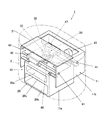
図1は、本実施形態におけるネイルプリント装置の外観を示す斜視図であり、図2は、ネイルプリント装置の内部構成を示す斜視図である。
An embodiment of a color correction printing apparatus according to the present invention will be described with reference to FIGS. In this embodiment, a case where the color correction printing apparatus is a nail printing apparatus will be described as an example. However, the color correction printing apparatus is not limited to a nail printing apparatus.
FIG. 1 is a perspective view illustrating an appearance of a nail print apparatus according to the present embodiment, and FIG. 2 is a perspective view illustrating an internal configuration of the nail print apparatus.
図1に示すように、このネイルプリント装置1は、ケース本体2及び蓋体4を備えている。このケース本体2及び蓋体4は、ケース本体2の上面後端部に設けたヒンジ3を介して、互いに連結されている。
As shown in FIG. 1, the nail printing apparatus 1 includes a
上記ケース本体2は平面視で長円状に形成されている。このケース本体2には前側には開閉板2cが起倒可能に設けられている。この開閉板2cは、ケース本体2の前面下端部に設けたヒンジ(図示せず)を介して、ケース本体2に連結されている。この開閉板2cは、ケース本体2の前面を開閉するためのものである。
また、ケース本体2の天板2fには後述する操作部12が設置されており、天板2fのほぼ中央部には表示部13が設定されている。
なお、ケース本体2及び蓋体4の形状、構成はここに例示したものに限定されない。
The
An
Note that the shapes and configurations of the
また、ケース本体2にはネイルプリント装置1の装置本体10が収容されている。この装置本体10は、図2に示す印刷指固定手段を構成している印刷指固定部20、撮影手段を構成している撮影部30、印刷手段を構成している印刷部40及び制御手段を構成している制御装置50(図7参照)を備えている。これら印刷指固定部20、撮影部30、印刷部40及び制御装置50は機枠11に設けられている。
なお、機枠11は下部機枠11a及び上部機枠11bによって構成されている。そして、下部機枠11aは箱状に形成され、ケース本体2の内部下方に設置され、上部機枠11bは下部機枠11aの上方で且つケース本体2の内部上方に設置されている。
Further, the case
The
印刷指固定部20は、機枠11の中の下部機枠11aに設けられている。この下部機枠11aに設けられた印刷指挿入部20a、非印刷指挿入部20b及び掴み部20cによって印刷指固定部20が構成されている。
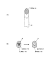
ここで、印刷指挿入部20aは、印刷しようとする爪Tに対応する指(以下「印刷指」という。)U1を挿入するめための指挿入部である(図3参照)。印刷指挿入部20aの底面(印刷指載置面)は、印刷指U1を載置する指載置手段として機能する。印刷指U1の撮影や印刷は、印刷指U1がこの指載置手段としての印刷指挿入部20aの印刷指載置面に載置された状態で行われる。
また、非印刷指挿入部20bは、印刷指以外の指(以下「非印刷指」という。)U2を挿入するための指挿入部である(図3参照)。
また、掴み部20cは、印刷指挿入部20aに挿入された印刷指U1と、非印刷指挿入部20bに挿入された非印刷指U2とで挟持することが可能な部分である。本実施形態において、この掴み部20cは印刷指挿入部20aと非印刷指挿入部20bとを仕切る隔壁21によって構成されている。
The printing
Here, the printing
Further, the non-printing
The gripping
この隔壁21の上面は平坦な印刷指載置面を構成している。この隔壁21の指挿入側端部には膨出部22が形成されている。この膨出部22は、印刷指挿入部20a及び非印刷指挿入部20bに印刷指U1及び非印刷指U2を深く挿入した際に、印刷指U1及び非印刷指U2の付け根U3が当接する部分に形成されている。膨出部22は、印刷指U1の腹全体が印刷指載置面に当接した状態で、印刷指U1と非印刷指U2とで隔壁21(掴み部20c)を強く挟持することができるように、指挿入方向の断面が、隔壁21の下面から下方に向けて膨出するように円形となっている。なお、膨出部22の形状は、断面円形に限定されることなく、断面楕円形,多角形等の非円形であってもよい。
The upper surface of the
例えば、左手の親指以外の4本の指(人差し指、中指、薬指及び小指)が印刷指U1となる場合には、図3に示すように、ユーザは印刷指挿入部20aに4本の印刷指U1を挿入し、非印刷指挿入部20bに非印刷指U2である親指を挿入する。この場合、ユーザが印刷指挿入部20aに挿入された印刷指U1と、非印刷指挿入部20bに挿入された非印刷指U2とで掴み部20cを挟持することにより、印刷指U1が掴み部20cの上で固定される。
また、親指のみが印刷指U1となる場合には、親指(印刷指U1)を印刷指挿入部20aに挿入さし、親指以外の4本の指(非印刷指U2)を非印刷指挿入部20bに挿入する。この場合にも、ユーザが印刷指U1と非印刷指U2とで掴み部20cを挟持することで印刷指U1が固定される。
For example, when four fingers (index finger, middle finger, ring finger, and little finger) other than the thumb of the left hand are the print fingers U1, the user places four print fingers on the print
When only the thumb becomes the printing finger U1, the thumb (printing finger U1) is inserted into the printing
また、図4は、本実施形態に係るネイルプリント装置1の正面側の断面図であり、図5は、ネイルプリント装置1の側断面図である。また、図6は、印刷指挿入部20aに載置された印刷指U1と、撮影部30、印刷部40との位置関係を模式的に示す要部断面図である。
4 is a front sectional view of the nail printing apparatus 1 according to the present embodiment, and FIG. 5 is a sectional side view of the nail printing apparatus 1. FIG. 6 is a main part sectional view schematically showing the positional relationship between the printing finger U1 placed on the printing
図4及び図5に示すように、撮影部30は、機枠11の中の上部機枠11bに設けられている。
すなわち、上部機枠11bに設置された基板31の中央部下面には、ドライバーを内蔵した200万画素程度以上の画素を有するカメラ32が設置されている。また、基板31には、カメラ32を囲むように白色LED等の照明灯33が設置されている。撮影部30は、このカメラ32及び照明灯33を備えて構成されている。
As shown in FIGS. 4 and 5, the photographing
That is, a
この撮影部30は、図6に示すように、指載置手段である印刷指挿入部20aに載置された印刷指U1を撮影可能な位置に配置されており、印刷指U1を照明灯33によって照明し、カメラ32によってその印刷指U1を撮影して、指爪画像を得る撮影手段として機能する。
また、本実施形態では、撮影部30によって取得された指爪画像に基づいて、後述する印刷対象濃度値取得部54が、印刷対象である印刷指U1の爪部Tの被印刷面(すなわち、爪部Tの表面)の濃度値を取得するようになっている。すなわち、印刷対象濃度値取得部54は、カメラ32によって撮影された指爪画像に基づいて、印刷指U1の爪部Tの表面の各色(後述するように、本実施形態ではY,M,C,Kの4色)ごとの濃度値を検出する。
この撮影部30は、後述する制御装置50の本体制御部52に接続され、該本体制御部52によって制御されるようになっている。
As shown in FIG. 6, the photographing
In the present embodiment, based on the fingernail image acquired by the photographing
The photographing
また、印刷部40は、印刷データに基づいて印刷対象の被印刷面である印刷指U1の爪部Tの表面に画像を印刷する印刷手段である。印刷部40は、後述する印刷データ補正部55によって印刷データの各色ごとの濃度値が補正されたときは、補正後の印刷データに基づいて印刷対象の被印刷面である印刷指U1の爪部Tの表面に画像を印刷する。
本実施形態において、印刷部40は、主に上部機枠11bに設けられている。すなわち、図4及び図5に示すように、上部機枠11bの両側板には、2本のガイドロッド41が平行に架設されている。このガイドロッド41には、主キャリッジ42が摺動自在に設置されている。また、図5に示すように、主キャリッジ42の前壁42aおよび後壁42bには2本のガイドロッド44が平行に架設されている。このガイドロッド44には、副キャリッジ45が摺動自在に設置されている。この副キャリッジ45の下面中央部には、印刷ヘッド46が搭載されている。
本実施形態において、この印刷ヘッド46は、インクを微滴化し、印刷対象の被印刷面に対し直接に吹き付けて印刷を行うインクジェット方式の印刷ヘッドである。なお、印刷ヘッド46の記録方式はインクジェット方式に限定されない。
The
In the present embodiment, the
In the present embodiment, the
本実施形態における印刷部40は、光透過性インクを用いて印刷を行うものである。光透過性インクは、印刷対象の被印刷面である印刷指U1の爪部Tの表面の色及び爪部Tの表面に既に印刷されている色を透過させ、その色と重なり合うことによって各種の色を表現する。本実施形態では、黄色(Y;YELLOW)、赤色(M;MAGENTA)、青色(C;CYAN)、黒色(K;BLACK)のインクを適宜重ねて印刷することによって、黄色(Y)、赤色(M)、青色(C)、黒色(K)、その他これらの色が重なり合い混色することによって生じる各種の色を表現するようになっている。なお、本実施形態では、印刷部40が、ここに例示した4色のインクに対応した4つの印刷ヘッド46を備えている場合を例として説明するが、印刷部40により吐出されるインクはこの4色のインクに限定されない。その他の色のインクを吐出させる印刷ヘッド46をさらに備えていてもよい。
The
主キャリッジ42は動力伝達手段(図示せず)を介してモータ43に連結され、モータ43の正逆回転によって、ガイドロッド41に沿って左右方向に移動ように構成されている。また、副キャリッジ45は動力伝達手段(図示せず)を介してモータ47に連結され、モータ47の正逆回転によって、ガイドロッド44に沿って前後方向に移動するように構成されている。
また、下部機枠11aには、印刷ヘッド46にインクを供給するためのインクカートリッジ48が設けられている。インクカートリッジ48は、図示しないインク供給管を介して印刷ヘッド46と接続されており、適宜印刷ヘッド46にインクを供給するようになっている。なお、印刷ヘッド46自体にインクカートリッジを搭載する構成としてもよい。
The
Further, the
印刷部40は、これらガイドロッド41、主キャリッジ42、モータ43、ガイドロッド44、副キャリッジ45、印刷ヘッド46、モータ47及びインクカートリッジ48等を備えて構成されている。この印刷部40のモータ43、印刷ヘッド46、モータ47は、後述する制御装置50の本体制御部52に接続され、該本体制御部52によって制御されるようになっている。
The
操作部12は、ユーザが各種入力を行うための入力手段である。
操作部12には、例えば、ネイルプリント装置1の電源をONする電源スイッチ釦、動作を停止させる停止スイッチ釦、爪部Tに印刷するデザイン画像D(図10等参照)を選択するデザイン選択釦、印刷開始を指示する印刷開始釦、その他各種の入力を行うための操作釦121が配置されている。
本実施形態では、例えば表示部13にデザイン画像Dを選択するための図示しないデザイン選択画面が表示されるようになっており、ユーザは、所望のデザイン画像Dを操作釦121によって選択することにより、印刷されるデザイン画像Dが選択される。
The
The
In the present embodiment, for example, a design selection screen (not shown) for selecting the design image D is displayed on the
表示部13は、例えば液晶パネル(液晶ディスプレイ(LCD:Liquid Crystal Display))等で構成された表示手段である。
なお、表示部13の表面に、タッチパネルが一体的に構成されていてもよい。この場合には、図示しないスタイラスペンや指先等によるタッチ操作により、表示部13の表面をタッチすることによっても各種の入力を行うことができるように構成される。
The
A touch panel may be integrally formed on the surface of the
表示部13には、例えば、印刷指U1を撮影した指爪画像、印刷指U1の爪部Tに印刷すべきデザイン画像Dを選択するためのデザイン選択画面、デザイン確認用のサムネイル画像等が表示されるようになっている。
なお、表示部13の表面にタッチパネルが一体的に構成されていてもよい。この場合には、表示部13の表面をユーザがタッチするだけで各種の入力操作等を行うことができるように構成される。
The
A touch panel may be integrally formed on the surface of the
また、制御装置50は、例えば上部機枠11bに配置された基板31等に設置されている。図7は、本実施形態における制御構成を示す要部ブロック図である。
Moreover, the
制御装置50は、図示しないCPU(Central Processing Unit)の他、ROM(Read Only Memory)、RAM(Random Access Memory)等(全て図示せず)で構成される記憶部51を備えるコンピュータである。
The
記憶部51には、爪部Tの表面に印刷されるデザイン画像Dの印刷データに含まれる各色ごとの濃度値を取得するための画像濃度値取得プログラム、爪部Tの表面の各色ごとの濃度値を取得する印刷対象濃度値取得プログラム、爪部Tの表面の濃度値と爪部Tに印刷すべき画像の濃度値とに基づいて、印刷データの各色ごとの濃度値を補正するための印刷データ補正プログラム、印刷処理を行うための印刷プログラム等の各種プログラムが格納されており、制御装置50はこれらのプログラムを実行してネイルプリント装置1の各部を制御するようになっている。
The
本実施形態において記憶部51には、撮影部30によって取得されたユーザの印刷指U1の指爪画像等が記憶される。
また、記憶部51には、デザイン画像Dの印刷データを記憶するデザイン画像保持領域511が設けられている。このデザイン画像の印刷データには、各色(本実施形態では黄色Y,赤色M,青色C,黒色Kの4色。なお、以下においてY,M,C,Kは、それぞれ黄色,赤色,青色,黒色の各色を表す。)ごとの濃度値が色情報として含まれている。
また、記憶部51には、後述する印刷データ補正手段としての印刷データ補正部55による補正の要否を判断するための基準となる印刷対象の被印刷面(本実施形態では、印刷指U1の爪部Tの表面)の各色ごとの色基準値を記憶している色基準値記憶手段としての色基準値保持領域512が設けられている。
In the present embodiment, the
The
The
印刷データは、印刷対象の被印刷面の色として一般的とされる色(例えば爪部Tの表面であれば薄いピンク色、印刷用紙の表面であれば白色等)の上に光透過性インクによる印刷を施すことを想定した場合に最も適した発色となるように各色の濃度値が定められている。本実施形態では、実際の被印刷面の色が印刷対象の被印刷面の色として一般的とされる色の濃度値と異なる場合に全て印刷データ補正部55による補正を行うのではなく、実際の被印刷面の色が印刷対象の被印刷面の色として一般的とされる色の濃度と一定濃度以上異なる場合にのみ各色ごとの濃度を補正するようになっており、色基準値は、この補正を行うか否かを判断するための許容値又は閾値としての機能を果たすものである。
色基準値は、例えばY10,M10,C10,K10等のように、各色ごとに定められている。なお、ここに挙げた色基準値の値は例示であり、色基準値の値はこれに限定されない。色基準値の値は各色ごとに適宜設定可能であり、例えば各色ごとに異なる値であってもよい。また、複数の印刷対象(例えば何も塗っていない生の爪部Tと既にネイルプリントを施した爪部T等)が想定され、それぞれに異なる印刷データが用意されている場合には、各印刷対象ごとに異なる色基準値が設定され、記憶されていてもよい。
The print data includes a light-transmitting ink on a color generally used as a color of a printing surface to be printed (for example, a light pink color for the surface of the nail portion T, a white color for the surface of the printing paper). The density value of each color is determined so as to achieve the most suitable color when it is assumed that printing is performed. In the present embodiment, when the actual color of the printing surface is different from the density value of the color that is generally used as the color of the printing surface to be printed, all corrections are not performed by the print
The color reference value is determined for each color, such as Y10, M10, C10, K10, and the like. In addition, the value of the color reference value mentioned here is an example, and the value of the color reference value is not limited to this. The value of the color reference value can be set as appropriate for each color, and may be a different value for each color, for example. In addition, when a plurality of print targets (for example, a raw nail portion T on which nothing is applied and a nail portion T which has already been subjected to nail printing) are assumed and different print data are prepared for each, Different color reference values may be set and stored for each target.
本実施形態において制御装置50は、本体制御部52、画像濃度値取得部53、印刷対象濃度値取得部54、印刷データ補正部55等の機能部を含んでいる。なお、制御装置50に含まれる機能部はここに挙げたものに限定されず、例えば、指爪画像から爪部Tの領域を検出する爪領域検出部等の機能部を備えていてもよい。
In the present embodiment, the
本体制御部52は、ネイルプリント装置1の全体を統括制御する機能部である。
本実施形態では、本体制御部52は、撮影部30を制御してユーザの印刷指U1を撮影させ、指爪画像を取得させる撮影制御手段として機能する。また、本体制御部52は、後述する印刷データを印刷部40に出力して、この印刷データにしたがって爪部Tに印刷を施すように印刷部40を制御する印刷制御手段として機能する。
The main
In the present embodiment, the main
画像濃度値取得部53は、印刷対象の被印刷面であるユーザの印刷指U1の爪部Tの表面に印刷される画像の印刷データに含まれる各色(すなわち、Y,M,C,K)ごとの濃度値を取得する画像濃度値取得手段である。画像濃度値取得部53によって取得された濃度値は、記憶部51に記憶される。
濃度値は、画像全体として取得されてもよいし、画像を構成する各画素ごとに取得されてもよいし、絵柄の領域と背景の領域等、ある領域ごとに取得されてもよい。本実施形態では画像全体としての濃度値を取得する場合を例として説明する。
The image density
The density value may be acquired for the entire image, may be acquired for each pixel constituting the image, or may be acquired for each region such as a pattern region and a background region. In this embodiment, a case where the density value of the entire image is acquired will be described as an example.
印刷対象濃度値取得部54は、撮影部30によって撮影された指爪画像から、印刷対象の被印刷面であるユーザの印刷指U1の爪部Tの表面の各色ごとの濃度値を取得する印刷対象濃度値取得手段である。
印刷対象濃度値取得部54は、指爪画像のうち爪部Tの領域について、例えば、Y20,M10,C0,K0のように各色ごとの濃度値を検出するようになっている。印刷対象濃度値取得部54によって取得された濃度値は、記憶部51に記憶される。
The printing target density
The print target density
印刷データ補正部55は、印刷対象濃度値取得部54により取得された被印刷面(すなわち、本実施形態ではユーザの爪部Tの表面)の各色ごとの濃度値と画像濃度値取得部53により取得された画像の各色ごとの濃度値とに基づいて、印刷データの各色ごとの濃度値を補正する印刷データ補正手段である。
本実施形態では、印刷データ補正部55は、印刷対象濃度値取得部54により取得された各色ごとの爪部Tの表面の濃度値と画像濃度値取得部53により取得された画像の各色ごとの濃度値との差分値を求め、各色ごとに得られた差分値に基づいて印刷データの濃度値を補正する。
また、印刷データ補正部55は、印刷対象濃度値取得部54により取得された被印刷面である爪部Tの表面の各色ごとの濃度値と色基準値保持領域512に記憶されている各色ごとの色基準値とを比較して補正の要否を判断し、爪部Tの表面の各色のうち、その濃度が色基準値以上である色について印刷データの濃度値を補正するようになっている。
The print
In the present embodiment, the print
The print
具体的には、例えば、印刷データの各色ごとの濃度値がY30、M10、C10、K10であり、ユーザの爪部Tの各色ごとの濃度値がY20、M0、C0、K0であり、色基準値がY10、M10、C10、K10の場合には、ユーザの爪部Tの各色ごとの濃度値のうちYのみが閾値(許容値)である色基準値以上となっている(Y20>Y10)。この場合、印刷データのYの濃度値がY30でありユーザの爪部TのYの濃度値がY20であり、印刷データを補正せずに印刷を行うと、爪部Tの表面にすでにあるY20の上にさらにY30を重ねて印刷することになるため、印刷後のYの濃度は50となり、もともと予定されていた濃度値を大きく超えてしまう。実際の印刷対象であるユーザの爪部Tの色を考慮すると、図8(A)及び図8(B)に示すように、もともと予定されていた濃度値(本実施形態ではY30)とするのに足りない濃度は爪部TのYの濃度値(本実施形態ではY20)ともともと予定されていた濃度値(Y30)との差分であるY10である。このため、印刷データ補正部55は、Yについてのみユーザの爪部TのYの濃度値(Y20)と印刷すべき画像の濃度値(Y30)との差分値を求めて、印刷データのYの濃度値をこの差分値(本実施形態ではY10)とする補正を行う。これにより、補正後の印刷データの各色ごとの濃度値は、Y10、M10、C10、K10となり、この補正後の印刷データに基づいて印刷が行われる。
また、例えば、印刷データの各色ごとの濃度値がY50、M40、C40、K20であり、ユーザの爪部Tの各色ごとの濃度値がY20、M20、C20、K10であり、色基準値がY10、M10、C10、K10の場合には、全ての色が閾値(許容値)である色基準値以上となっている。この場合には、印刷データ補正部55は、全ての色についてユーザの爪部Tの各色ごとの濃度値と印刷すべき画像の各色ごとの濃度値との差分値を求めて、印刷データの各色ごとの濃度値をこの差分値とする補正を行う。これにより、補正後の印刷データの各色ごとの濃度値は、Y30、M20、C20、K10となり、この補正後の印刷データに基づいて印刷が行われる。
また、例えば、印刷データの各色ごとの濃度値がY50、M30、C40、K20であり、ユーザの爪部Tの各色ごとの濃度値がY20、M10、C7、K5であり、色基準値がY10、M10、C10、K10の場合には、Y,Mのみが閾値(許容値)である色基準値以上となっている。この場合には、印刷データ補正部55は、Y,Mのみについてのみユーザの爪部Tの濃度値と印刷すべき画像の濃度値との差分値を求めて、印刷データの各色ごとの濃度値をこの差分値とする補正を行う。これにより、補正後の印刷データの各色ごとの濃度値は、Y30、M20、C40、K20となり、この補正後の印刷データに基づいて印刷が行われる。なお、この場合、ユーザの爪部Tの表面の色C,Kの濃度値はそれぞれC7、K5であるため、C,Kについてこのまま印刷を行うと、C47、K25となるが、色基準値以下である色については多少濃度値が大きくなっても誤差の範囲内として許容する。
なお、例えば、印刷データの各色ごとの濃度値がY50、M30、C20、K20であり、ユーザの爪部Tの各色ごとの濃度値がY8、M5、C30、K7であり、色基準値がY10、M10、C10、K10の場合には、Cについては閾値(許容値)である色基準値以上であり、さらに印刷データのCの濃度値を超えている。このように、ユーザの爪部Tの各色ごとの濃度値と印刷すべき画像の各色ごとの濃度値との差分値がマイナスの値になるような場合、既に爪部Tに施されている色以下の濃度にする補正はできないため、この場合には、印刷データ補正部55は、当該Cの濃度値を0と補正する。印刷データの各色ごとの濃度値をこの差分とする補正を行う。これにより、補正後の印刷データの各色ごとの濃度値は、Y50、M30、C0、K20となり、この補正後の印刷データに基づいて印刷が行われる。
印刷データ補正部55による補正が行われた場合には、補正後の印刷データが印刷部40に出力されて、印刷部40により補正後の印刷データに基づいて爪部Tの表面への印刷が行われる。印刷データ補正部55による補正が行われなかった場合には、もとの印刷データが印刷部40に出力されて、印刷部40によりこの印刷データに基づいて爪部Tの表面への印刷が行われる。
Specifically, for example, the density values for each color of the print data are Y30, M10, C10, and K10, and the density values for each color of the user's nail portion T are Y20, M0, C0, and K0. When the values are Y10, M10, C10, and K10, only Y among the density values for each color of the user's nail portion T is equal to or greater than a color reference value that is a threshold value (allowable value) (Y20> Y10). . In this case, the Y density value of the print data is Y30, the Y density value of the user's nail portion T is Y20, and if printing is performed without correcting the print data, the Y20 already on the surface of the nail portion T is printed. Since Y30 is further overlaid on top of the image, the Y density after printing is 50, which greatly exceeds the originally planned density value. In consideration of the color of the user's nail portion T, which is the actual print target, as shown in FIGS. 8A and 8B, the originally planned density value (Y30 in this embodiment) is used. The density that is insufficient is Y10 that is the difference between the Y density value of the nail portion T (Y20 in the present embodiment) and the originally planned density value (Y30). For this reason, the print
Further, for example, the density values for each color of the print data are Y50, M40, C40, K20, the density values for each color of the user's nail portion T are Y20, M20, C20, K10, and the color reference value is Y10. , M10, C10, and K10, all colors are equal to or greater than a color reference value that is a threshold value (allowable value). In this case, the print
Further, for example, the density values for each color of the print data are Y50, M30, C40, and K20, the density values for each color of the user's nail portion T are Y20, M10, C7, and K5, and the color reference value is Y10. , M10, C10, and K10, only Y and M are equal to or greater than the color reference value that is a threshold value (allowable value). In this case, the print
For example, the density values for each color of the print data are Y50, M30, C20, and K20, the density values for each color of the user's nail portion T are Y8, M5, C30, and K7, and the color reference value is Y10. , M10, C10, and K10, C is equal to or greater than a color reference value that is a threshold value (allowable value), and further exceeds the C density value of the print data. Thus, when the difference value between the density value for each color of the user's nail portion T and the density value for each color of the image to be printed is a negative value, the color already applied to the nail portion T. In this case, the print
When the correction by the print
次に、図9から図13を参照しつつ、本実施形態におけるネイルプリント装置1による印刷制御方法について説明する。
このネイルプリント装置1により印刷を行う場合、ユーザはまず、電源スイッチを入れて制御装置50を起動させる。
本体制御部52は、表示部13にデザイン選択画面を表示させ、ユーザは操作部12の操作釦121等を操作して、デザイン選択画面に表示された複数のデザイン画像Dの中から所望のデザイン画像Dを選択することにより、操作部12から選択指示信号が出力されて一つのデザイン画像Dが選択される。
印刷すべきデザイン画像Dが選択されると、図9に示すように、画像濃度値取得部53は、当該デザイン画像Dの印刷データを記憶部51のデザイン画像保持領域511から読み出して取得し(ステップS1)、当該印刷データに含まれる各色ごとの濃度値を取得する(ステップS2)。
Next, a print control method by the nail print apparatus 1 in the present embodiment will be described with reference to FIGS. 9 to 13.
When printing is performed by the nail printing apparatus 1, the user first turns on the power switch to activate the
The main
When the design image D to be printed is selected, as shown in FIG. 9, the image density
次に、ユーザは、印刷指U1を印刷指挿入部20aに挿入し、非印刷指U2を非印刷指挿入部20bに挿入して、印刷指U1を固定した上で、印刷スイッチを操作する。
例えば、左手の人差し指、中指、薬指及び小指の爪部Tに印刷を施したい場合には、図3に示すように、印刷指挿入部20aに人差し指、中指、薬指及び小指を平面的に並べて挿入し、非印刷指挿入部20bに親指を挿入する。そして、印刷指挿入部20aに挿入した人差し指、中指、薬指及び小指と非印刷指挿入部20bに挿入した親指とで掴み部20cを挟持する。これによって、印刷指U1である人差し指、中指、薬指及び小指が固定される。
Next, the user inserts the printing finger U1 into the printing
For example, when printing is to be performed on the index finger, middle finger, ring finger, and nail portion T of the little finger of the left hand, the index finger, middle finger, ring finger, and little finger are inserted in a plane in the print
制御装置50は、印刷スイッチから指示が入力されると、印刷動作を開始する前に、まず撮影部30を制御して、印刷指U1全体を撮影させる。これにより、印刷指U1の指爪画像が取得される(ステップS3)。指爪画像が取得されると、印刷対象濃度値取得部54は、この指爪画像から爪部Tの表面の各色ごとの濃度値を取得する(ステップS4)。
印刷データ補正部55は、記憶部51の色基準値保持領域512から各色ごとの色基準値を読み出し、印刷対象濃度値取得部54によって取得された爪部Tの表面の各色ごとの濃度値が色基準値以上か否かを判断する(ステップS5)。そして、爪部Tの表面の各色ごとの濃度値が色基準値以上でないと判断した場合(ステップS5;NO)には、印刷データ補正部55は印刷データの補正を行わず、もとの印刷データがそのまま印刷部40に出力されて、この印刷データに基づいて印刷部40による印刷が行われる(ステップS6)。
すなわち、例えば、図10に示すように、ユーザの印刷指U1の爪部Tが何も着色等されておらず、Y,M,C,Kいずれの濃度値も色基準値を超えていない場合には、もとの印刷データに基づいてそのままデザイン画像Dの印刷が行われる。
When an instruction is input from the print switch, the
The print
That is, for example, as shown in FIG. 10, when the nail portion T of the user's printing finger U1 is not colored, the density values of any of Y, M, C, and K do not exceed the color reference value. The design image D is printed as it is based on the original print data.
これに対して、爪部Tの表面の各色のうちいずれかの色の濃度値が色基準値以上であると判断した場合(ステップS5;YES)には、印刷データ補正部55は、基準値以上であった色について、爪にTの表面の各色ごとの濃度値と印刷すべき画像の各色ごとの濃度値との差分を算出する(ステップS7)。そして、算出された差分値を当該色の濃度値として印刷データの補正を行う(ステップS8)。そして、補正後の印刷データが印刷部40に出力されて、この補正後の印刷データに基づいて印刷部40による印刷が行われる(ステップS9)。
On the other hand, when it is determined that the density value of any one of the colors on the surface of the nail portion T is greater than or equal to the color reference value (step S5; YES), the print
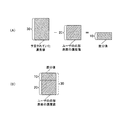
例えば、図11(B)、図12(B)、図13(B)に示すように、選択されたデザイン画像Dが、濃い青色(青色Cの濃度値100)の背景部分Hと濃い赤色(例えば赤色Mの濃度値100)のハートの絵柄部分Eとから構成されている場合には、ユーザの爪部Tの表面の色に応じて以下のような印刷データの補正が行われる。
すなわち、例えば、図11(A)に示すように、ユーザの爪部Tの表面に既に薄い赤色(例えば赤色Mの濃度値50)が塗られている場合には、図11(B)に示すように、印刷データ補正部55は、赤色Mについて、爪部Tの表面の赤色Mの濃度値50とデザイン画像Dのハートの絵柄部分Eの赤色Mの濃度値100との差分値である50を印刷データの赤色Mの濃度値とし、印刷データを補正する。これにより、ユーザの爪部Tの表面に補正後の印刷データに基づいて印刷を行った場合に、赤色についてもともと予定されていた濃度値100が実現される。
また、例えば、図12(A)に示すように、ユーザの爪部Tの表面に既に濃い赤色(例えば赤色Mの濃度値100)が塗られている場合には、図12(B)に示すように、印刷データ補正部55は、赤色Mについて、爪部Tの表面の赤色Mの濃度値100とデザイン画像Dのハートの絵柄部分Eの赤色Mの濃度値100との差分値である0を印刷データの赤色Mの濃度値とし、印刷データを補正する。これにより、ユーザの爪部Tの表面に補正後の印刷データに基づいて印刷を行った場合に、赤色Mについてもともと予定されていた濃度値100が実現される。
また、例えば、図13(A)に示すように、ユーザの爪部Tの表面に既に薄い青色(例えば青色Cの濃度値50)が塗られている場合には、図13(B)に示すように、印刷データ補正部55は、青色Cについて、爪部Tの表面の青色Cの濃度値50とデザイン画像Dの背景部分Hの青色Cの濃度値100との差分値である50を印刷データの青色Cの濃度値とし、印刷データを補正する。これにより、ユーザの爪部Tの表面に補正後の印刷データに基づいて印刷を行った場合に、青色Cについてもともと予定されていた濃度値100が実現される。
For example, as shown in FIG. 11B, FIG. 12B, and FIG. 13B, the selected design image D has a background portion H of dark blue (
That is, for example, as shown in FIG. 11A, when the surface of the user's nail portion T is already painted with a light red color (for example, the
Further, for example, as shown in FIG. 12A, when the surface of the user's nail portion T is already painted with a deep red color (for example, the
Further, for example, as shown in FIG. 13A, when the surface of the user's nail portion T is already painted with a light blue color (for example, a
以上のように、本実施形態におけるネイルプリント装置1によれば、印刷対象の被印刷面であるユーザの印刷指U1の爪部Tの表面に印刷されるデザイン画像Dの印刷データに含まれている各色ごとの濃度値を取得するとともに、爪部Tの表面の各色ごとの濃度値を取得して、この爪部Tの表面の濃度値と印刷される画像の濃度値とに基づいて印刷データの各色ごとの濃度値を補正し、補正後の印刷データに基づき、光透過性インクを用いて爪部Tの表面にデザイン画像Dを印刷するようになっている。このため、印刷対象の被印刷面であるユーザの印刷指U1の爪部Tの表面に既に何らかの印刷が施されていたり、着色されている等により、薄いピンク色等一般的な爪部T表面の色以外の色の爪部Tの表面に印刷を施す場合でも、爪部Tの表面の色を考慮した上で、イメージ通りの発色のデザイン画像Dを印刷することができる。
また、印刷データ補正部55は、印刷対象濃度値取得部54により取得された各色ごとの爪部Tの表面の濃度値と画像濃度値取得部53により取得されたデザイン画像Dの各色ごとの濃度値との差分値を求め、各色ごとに得られた差分値に基づいて印刷データの濃度値を補正するようになっている。このため、ユーザの印刷指U1の爪部Tの表面の色を考慮して印刷するインクの濃度を調整することができ、爪部Tの表面既に何らかの着色がなされているような場合には、その色を生かして印刷を行うことによりインクを無駄に重ね打ちすることを防止して効率よく所望の発色を実現することができる。
また印刷データ補正部55は、印刷対象濃度値取得部54により取得された爪部Tの表面の各色ごとの濃度値と色基準値保持領域512に記憶されている各色ごとの色基準値とを比較して、色基準値を超えている色についてのみ印刷データの濃度値を補正する。このため、爪部Tの表面の各色ごとの濃度値ともともとの印刷データが想定している一般的な爪部Tの色との差異が印刷の仕上がりにあまり影響を与えない程度であれば、補正せずに印刷処理を行うことができ、処理の効率化を図ることができる。
As described above, according to the nail print apparatus 1 in the present embodiment, it is included in the print data of the design image D printed on the surface of the nail portion T of the user's printing finger U1 that is the printing target surface to be printed. Print data based on the density value of the surface of the nail portion T and the density value of the image to be printed. The design image D is printed on the surface of the nail portion T using light transmissive ink based on the corrected print data. For this reason, the surface of the nail part T of the user's printing finger U1 that is the printing target surface to be printed has already been subjected to some printing or is colored, so that a general nail part T surface such as a light pink color Even when printing is performed on the surface of the nail portion T of a color other than the above color, it is possible to print the design image D that is colored as the image in consideration of the color of the surface of the nail portion T.
The print
The print
なお、本実施形態では、補正をするか否かを判断するための閾値として色基準値を記憶させておき、実際の被印刷面(本実施形態では爪部Tの表面)の色の濃度値がこの色基準値を超える場合にのみ各色ごとの濃度値を補正する場合を例としたが、色基準値の設定及び補正するか否かの判断処理は本発明の必須の要素ではなく、これを備えない構成としてもよい。この場合には、実際の印刷対象の被印刷面(例えばユーザの爪部Tの表面)の各色の濃度値が当該印刷対象の被印刷面(一般的な爪部Tの表面)において一般的とされる各色の濃度値と少しでも異なる場合には一律に印刷データの各色ごとの濃度値を補正する。 In this embodiment, a color reference value is stored as a threshold value for determining whether or not correction is performed, and the color density value of the color on the actual printed surface (the surface of the nail portion T in this embodiment) is stored. In this example, the density value for each color is corrected only when the color reference value exceeds this color reference value. However, the setting of the color reference value and the determination process for whether or not to correct the color reference value are not essential elements of the present invention. It is good also as a structure which is not provided. In this case, the density value of each color on the actual printing target surface (for example, the surface of the user's nail portion T) is generally determined on the printing target surface (the surface of the general nail portion T). If the density value of each color is slightly different, the density value for each color of the print data is corrected uniformly.
また、本実施形態では、色補正印刷装置が、印刷対象の被印刷面として印刷指U1の爪部Tの表面に印刷を施すネイルプリント装置1である場合を例として説明したが、色補正印刷装置はネイルプリント装置1に限定されない。例えば、各種印刷用紙に印刷を施す印刷装置でもよい。この場合には、印刷用紙の表面の各色の濃度値に応じて補正を行う。
なお、複数の印刷対象に印刷を行うことが予定されており、各印刷対象の被印刷面の色に応じて印刷データが用意されている場合には、色基準値も各印刷対象ごとに用意されていてもよい。例えば、白色の印刷用紙に印刷する場合と薄いベージュ色の再生紙に印刷する場合とで異なる印刷データが用意されている場合には、色基準値も白色の印刷用紙用の色基準値と薄いベージュ色の再生紙用の色基準値が用意され、印刷対象に応じて対応する色基準値が選択的に用いられるようにしてもよい。
In the present embodiment, the color correction printing apparatus has been described as an example in which the color correction printing apparatus is the nail printing apparatus 1 that performs printing on the surface of the nail portion T of the printing finger U1 as a printing target surface. The apparatus is not limited to the nail printing apparatus 1. For example, a printing apparatus that performs printing on various printing papers may be used. In this case, correction is performed according to the density value of each color on the surface of the printing paper.
If printing is planned for multiple print targets and print data is prepared according to the color of the print target surface of each print target, a color reference value is also prepared for each print target. May be. For example, when different print data is prepared for printing on white printing paper and printing on light beige recycled paper, the color reference value is also lighter than the color reference value for white printing paper. A color reference value for beige recycled paper may be prepared, and the corresponding color reference value may be selectively used according to the print target.
また、本実施形態では、印刷対象濃度値取得部54により取得された被印刷面(本実施形態では爪部Tの表面)の各色ごとの濃度値と画像濃度値取得部53により取得されたデザイン画像Dの各色ごとの濃度値とに基づいて、印刷データ補正部55が印刷データの各色ごとの濃度値を補正する場合を例として説明したが、印刷データ補正部55が補正するのは印刷データの各色ごとの濃度値に限定されない。
また、印刷データ補正部55が印刷データを補正する手法は、被印刷面(本実施形態では爪部Tの表面)の各色ごとの濃度値とデザイン画像Dの各色ごとの濃度値との差分値を求める手法に限定されない。例えば、各色ごとの濃度値以外の色情報に基づいて印刷データの補正を行ってもよい。
In this embodiment, the density value for each color of the printing surface (the surface of the nail portion T in the present embodiment) acquired by the print target density
The print
また、本実施形態では、デザイン画像保持領域511、色基準値保持領域512が制御装置50の記憶部51内に設けられている場合を例としたが、デザイン画像保持領域511、色基準値保持領域512は制御装置50の記憶部51に設けられている場合に限定されず、別途記憶部が設けられていてもよい。
In this embodiment, the design
また、本実施形態では、4本の指に対して同時に印刷を行うことのできるネイルプリント装置1を例としたが、指を1本ずつ装置に挿入して順次印刷を行う装置に本発明を適用することも可能である。 In the present embodiment, the nail printing apparatus 1 capable of simultaneously printing on four fingers is taken as an example. However, the present invention is applied to an apparatus that performs printing sequentially by inserting fingers one by one into the apparatus. It is also possible to apply.
その他、本発明が本実施形態に限定されず、適宜変更可能であることはいうまでもない。 In addition, it cannot be overemphasized that this invention is not limited to this embodiment, and can be changed suitably.
以上本発明のいくつかの実施形態を説明したが、本発明の範囲は、上述の実施の形態に限定するものではなく、特許請求の範囲に記載された発明の範囲とその均等の範囲を含む。
以下に、この出願の願書に最初に添付した特許請求の範囲に記載した発明を付記する。付記に記載した請求項の項番は、この出願の願書に最初に添付した特許請求の範囲の通りである。
〔付記〕
<請求項1>
光透過性インクを用い、印刷データに基づいて印刷対象の被印刷面に画像を印刷する印刷手段と、
この印刷手段により前記印刷対象の被印刷面に印刷される画像の印刷データに含まれる各色ごとの濃度値を取得する画像濃度値取得手段と、
前記印刷手段により前記印刷対象の被印刷面に印刷する前に、前記印刷対象の被印刷面の各色ごとの濃度値を取得する印刷対象濃度値取得手段と、
この印刷対象濃度値取得手段により取得された被印刷面の濃度値と前記画像濃度値取得手段により取得された画像の濃度値とに基づいて、前記印刷データの各色ごとの濃度値を補正する印刷データ補正手段と、
この印刷データ補正手段により補正された各色ごとの濃度値を有する補正後の印刷データに基づいて前記印刷対象の被印刷面に画像を印刷するように前記印刷手段を制御する印刷制御手段と、
を備えていることを特徴とする色補正印刷装置。
<請求項2>
前記印刷データ補正手段は、前記印刷対象濃度値取得手段により取得された各色ごとの前記被印刷面の濃度値と前記画像濃度値取得手段により取得された前記画像の各色ごとの濃度値との差分値を求め、各色ごとに得られた差分値に基づいて前記印刷データの濃度値を補正することを特徴とする請求項1に記載の色補正印刷装置。
<請求項3>
前記印刷データ補正手段による補正の要否を判断するための基準となる前記印刷対象の被印刷面の各色ごとの色基準値を記憶している色基準値記憶手段をさらに備え、
前記印刷データ補正手段は、前記印刷対象濃度値取得手段により取得された前記被印刷面の各色ごとの濃度値と前記色基準値記憶手段に記憶されている各色ごとの色基準値とを比較して、前記色基準値を超えている色について前記印刷データの濃度値を補正することを特徴とする請求項1又は請求項2に記載の色補正印刷装置。
<請求項4>
印刷対象の被印刷面に印刷される画像の印刷データに含まれる各色ごとの濃度値を取得する画像濃度値取得ステップと、
前記印刷対象の被印刷面の各色ごとの濃度値を取得する印刷対象濃度値取得ステップと、
この印刷対象濃度値取得ステップにおいて取得された被印刷面の濃度値と前記画像濃度値取得ステップにおいて取得された画像の濃度値とに基づいて、前記印刷データの各色ごとの濃度値を補正する印刷データ補正ステップと、
前記印刷データ補正ステップにおいて各色ごとの濃度値が補正された補正後の印刷データに基づき、光透過性インクを用いて、前記印刷対象の被印刷面に画像を印刷する印刷ステップと、
を含んでいることを特徴とする印刷制御方法。
<請求項5>
前記印刷データ補正ステップは、前記印刷対象濃度値取得ステップにおいて取得された各色ごとの前記被印刷面の濃度値と前記画像濃度値取得ステップにおいて取得された前記画像の各色ごとの濃度値との差分値を求め、各色ごとに得られた差分値に基づいて前記印刷データの濃度値を補正することを特徴とする請求項4に記載の印刷制御方法。
<請求項6>
前記印刷データ補正ステップは、前記印刷対象濃度値取得ステップにより取得された前記被印刷面の濃度値と前記印刷対象の被印刷面の各色ごとの基準色を示す色基準値とを比較して、前記色基準値を超えている色について前記印刷データの濃度値を補正することを特徴とする請求項4又は請求項5に記載の印刷制御方法。
Although several embodiments of the present invention have been described above, the scope of the present invention is not limited to the above-described embodiments, but includes the scope of the invention described in the claims and equivalents thereof. .
The invention described in the scope of claims attached to the application of this application will be added below. The item numbers of the claims described in the appendix are as set forth in the claims attached to the application of this application.
[Appendix]
<Claim 1>
Printing means for printing an image on a printing surface to be printed based on print data using light-transmitting ink;
Image density value acquisition means for acquiring a density value for each color included in print data of an image printed on the printing surface to be printed by the printing means;
A printing target density value acquisition unit that acquires a density value for each color of the printing target printing surface before printing on the printing target printing surface by the printing unit;
Printing for correcting the density value for each color of the print data based on the density value of the printing surface acquired by the print target density value acquisition unit and the density value of the image acquired by the image density value acquisition unit Data correction means;
A print control means for controlling the printing means to print an image on the printing surface to be printed based on the corrected print data having the density value for each color corrected by the print data correction means;
A color correction printing apparatus comprising:
<Claim 2>
The print data correction means includes a difference between the density value of the printing surface for each color acquired by the print target density value acquisition means and the density value for each color of the image acquired by the image density value acquisition means. The color correction printing apparatus according to claim 1, wherein a value is obtained and the density value of the print data is corrected based on a difference value obtained for each color.
<Claim 3>
A color reference value storage means for storing a color reference value for each color of the printing surface to be printed, which serves as a reference for determining whether correction by the print data correction means is necessary;
The print data correction unit compares the density value for each color of the printing surface acquired by the print target density value acquisition unit with the color reference value for each color stored in the color reference value storage unit. The color correction printing apparatus according to claim 1, wherein the density value of the print data is corrected for a color that exceeds the color reference value.
<Claim 4>
An image density value acquisition step for acquiring a density value for each color included in the print data of an image printed on a printing surface to be printed;
A print target density value acquisition step of acquiring a density value for each color of the printing target surface to be printed;
Printing that corrects the density value for each color of the print data based on the density value of the printing surface acquired in the print target density value acquisition step and the density value of the image acquired in the image density value acquisition step A data correction step;
A printing step of printing an image on the printing surface to be printed using light transmissive ink based on the corrected print data in which the density value for each color is corrected in the print data correction step;
A printing control method comprising:
<Claim 5>
The printing data correction step includes a difference between the density value of the printing surface for each color acquired in the printing target density value acquisition step and the density value for each color of the image acquired in the image density value acquisition step. The print control method according to
<Claim 6>
The print data correction step compares the density value of the printing surface acquired by the printing target density value acquisition step with a color reference value indicating a reference color for each color of the printing target printing surface, The print control method according to
1 ネイルプリント装置
2 ケース本体
20a 印刷指挿入部
30 撮影部
40 印刷部
50 制御装置
51 記憶部
52 本体制御部
53 画像濃度値取得部
54 印刷対象濃度値取得部
55 印刷データ補正部
511 デザイン画像保持領域
512 色基準値保持領域
T 爪
U1 印刷指
U2 非印刷指
DESCRIPTION OF SYMBOLS 1
Claims (6)
この印刷手段により前記印刷対象の被印刷面に印刷される画像の印刷データに含まれる各色ごとの濃度値を取得する画像濃度値取得手段と、
前記印刷手段により前記印刷対象の被印刷面に印刷する前に、前記印刷対象の被印刷面の各色ごとの濃度値を取得する印刷対象濃度値取得手段と、
この印刷対象濃度値取得手段により取得された被印刷面の濃度値と前記画像濃度値取得手段により取得された画像の濃度値とに基づいて、前記印刷データの各色ごとの濃度値を補正する印刷データ補正手段と、
この印刷データ補正手段により補正された各色ごとの濃度値を有する補正後の印刷データに基づいて前記印刷対象の被印刷面に画像を印刷するように前記印刷手段を制御する印刷制御手段と、
を備えていることを特徴とする色補正印刷装置。 Printing means for printing an image on a printing surface to be printed based on print data using light-transmitting ink;
Image density value acquisition means for acquiring a density value for each color included in print data of an image printed on the printing surface to be printed by the printing means;
A printing target density value acquisition unit that acquires a density value for each color of the printing target printing surface before printing on the printing target printing surface by the printing unit;
Printing for correcting the density value for each color of the print data based on the density value of the printing surface acquired by the print target density value acquisition unit and the density value of the image acquired by the image density value acquisition unit Data correction means;
A print control means for controlling the printing means to print an image on the printing surface to be printed based on the corrected print data having the density value for each color corrected by the print data correction means;
A color correction printing apparatus comprising:
前記印刷データ補正手段は、前記印刷対象濃度値取得手段により取得された前記被印刷面の各色ごとの濃度値と前記色基準値記憶手段に記憶されている各色ごとの色基準値とを比較して、前記色基準値を超えている色について前記印刷データの濃度値を補正することを特徴とする請求項1又は請求項2に記載の色補正印刷装置。 A color reference value storage means for storing a color reference value for each color of the printing surface to be printed, which serves as a reference for determining whether correction by the print data correction means is necessary;
The print data correction unit compares the density value for each color of the printing surface acquired by the print target density value acquisition unit with the color reference value for each color stored in the color reference value storage unit. The color correction printing apparatus according to claim 1, wherein the density value of the print data is corrected for a color that exceeds the color reference value.
前記印刷対象の被印刷面の各色ごとの濃度値を取得する印刷対象濃度値取得ステップと、
この印刷対象濃度値取得ステップにおいて取得された被印刷面の濃度値と前記画像濃度値取得ステップにおいて取得された画像の濃度値とに基づいて、前記印刷データの各色ごとの濃度値を補正する印刷データ補正ステップと、
前記印刷データ補正ステップにおいて各色ごとの濃度値が補正された補正後の印刷データに基づき、光透過性インクを用いて、前記印刷対象の被印刷面に画像を印刷する印刷ステップと、
を含んでいることを特徴とする印刷制御方法。 An image density value acquisition step for acquiring a density value for each color included in the print data of an image printed on a printing surface to be printed;
A print target density value acquisition step of acquiring a density value for each color of the printing target surface to be printed;
Printing that corrects the density value for each color of the print data based on the density value of the printing surface acquired in the print target density value acquisition step and the density value of the image acquired in the image density value acquisition step A data correction step;
A printing step of printing an image on the printing surface to be printed using light transmissive ink based on the corrected print data in which the density value for each color is corrected in the print data correction step;
A printing control method comprising:
Priority Applications (3)
| Application Number | Priority Date | Filing Date | Title |
|---|---|---|---|
| JP2011208453A JP2013067127A (en) | 2011-09-26 | 2011-09-26 | Color correction printing apparatus and print control method |
| US13/617,513 US20130077103A1 (en) | 2011-09-26 | 2012-09-14 | Color correction print apparatus and print control method |
| CN201210434345.9A CN103040227B (en) | 2011-09-26 | 2012-09-26 | Color correct printing equipment and printing control method |
Applications Claiming Priority (1)
| Application Number | Priority Date | Filing Date | Title |
|---|---|---|---|
| JP2011208453A JP2013067127A (en) | 2011-09-26 | 2011-09-26 | Color correction printing apparatus and print control method |
Publications (2)
| Publication Number | Publication Date |
|---|---|
| JP2013067127A true JP2013067127A (en) | 2013-04-18 |
| JP2013067127A5 JP2013067127A5 (en) | 2013-05-30 |
Family
ID=47910980
Family Applications (1)
| Application Number | Title | Priority Date | Filing Date |
|---|---|---|---|
| JP2011208453A Pending JP2013067127A (en) | 2011-09-26 | 2011-09-26 | Color correction printing apparatus and print control method |
Country Status (3)
| Country | Link |
|---|---|
| US (1) | US20130077103A1 (en) |
| JP (1) | JP2013067127A (en) |
| CN (1) | CN103040227B (en) |
Cited By (2)
| Publication number | Priority date | Publication date | Assignee | Title |
|---|---|---|---|---|
| JP2015047474A (en) * | 2013-09-05 | 2015-03-16 | カシオ計算機株式会社 | Nail printing device and printing method of nail printing device |
| JP2022110389A (en) * | 2021-01-18 | 2022-07-29 | カシオ計算機株式会社 | Printer, printing control method and program |
Families Citing this family (4)
| Publication number | Priority date | Publication date | Assignee | Title |
|---|---|---|---|---|
| JP6303413B2 (en) * | 2013-11-11 | 2018-04-04 | カシオ計算機株式会社 | Nail printing apparatus and printing method for nail printing apparatus |
| JP6756171B2 (en) | 2016-07-11 | 2020-09-16 | コニカミノルタ株式会社 | Image processing equipment, image forming equipment, image forming system, and image processing program |
| CN110239210B (en) * | 2018-03-09 | 2021-08-24 | 晋江千航服饰有限公司 | Color printing machine with color compensation |
| WO2021087161A1 (en) | 2019-10-29 | 2021-05-06 | NailPro, Inc. | Automated total nail care systems, devices and methods |
Citations (4)
| Publication number | Priority date | Publication date | Assignee | Title |
|---|---|---|---|---|
| JPH0740598A (en) * | 1993-07-27 | 1995-02-10 | Nec Corp | Print output method and its control device for serial printer |
| JPH0898047A (en) * | 1994-09-27 | 1996-04-12 | Oki Electric Ind Co Ltd | Color print processor |
| JPH10308878A (en) * | 1997-05-07 | 1998-11-17 | Canon Inc | Image processing unit and image processing method |
| JP2005203871A (en) * | 2004-01-13 | 2005-07-28 | Konica Minolta Business Technologies Inc | Dither pattern generating apparatus, method, and program |
Family Cites Families (6)
| Publication number | Priority date | Publication date | Assignee | Title |
|---|---|---|---|---|
| JPH09106130A (en) * | 1995-10-09 | 1997-04-22 | Ricoh Co Ltd | Image forming device |
| JPH09150569A (en) * | 1995-11-29 | 1997-06-10 | Riso Kagaku Corp | Color image forming sheet |
| JPH1044510A (en) * | 1996-08-08 | 1998-02-17 | Nec Corp | Color imaging system |
| JP2004216872A (en) * | 2002-12-27 | 2004-08-05 | Plenty:Kk | Nail art applying device |
| CN100375954C (en) * | 2003-10-30 | 2008-03-19 | 罗春晖 | Method of preparing pattern for beautifying nail through computer and digital nail beauty device applied |
| JP4407300B2 (en) * | 2004-01-30 | 2010-02-03 | ブラザー工業株式会社 | Image forming apparatus |
-
2011
- 2011-09-26 JP JP2011208453A patent/JP2013067127A/en active Pending
-
2012
- 2012-09-14 US US13/617,513 patent/US20130077103A1/en not_active Abandoned
- 2012-09-26 CN CN201210434345.9A patent/CN103040227B/en active Active
Patent Citations (4)
| Publication number | Priority date | Publication date | Assignee | Title |
|---|---|---|---|---|
| JPH0740598A (en) * | 1993-07-27 | 1995-02-10 | Nec Corp | Print output method and its control device for serial printer |
| JPH0898047A (en) * | 1994-09-27 | 1996-04-12 | Oki Electric Ind Co Ltd | Color print processor |
| JPH10308878A (en) * | 1997-05-07 | 1998-11-17 | Canon Inc | Image processing unit and image processing method |
| JP2005203871A (en) * | 2004-01-13 | 2005-07-28 | Konica Minolta Business Technologies Inc | Dither pattern generating apparatus, method, and program |
Cited By (4)
| Publication number | Priority date | Publication date | Assignee | Title |
|---|---|---|---|---|
| JP2015047474A (en) * | 2013-09-05 | 2015-03-16 | カシオ計算機株式会社 | Nail printing device and printing method of nail printing device |
| JP2022110389A (en) * | 2021-01-18 | 2022-07-29 | カシオ計算機株式会社 | Printer, printing control method and program |
| US11731441B2 (en) | 2021-01-18 | 2023-08-22 | Casio Computer Co., Ltd. | Printing device, print controlling method, and storage medium |
| JP7459807B2 (en) | 2021-01-18 | 2024-04-02 | カシオ計算機株式会社 | Printing device, printing control method and program |
Also Published As
| Publication number | Publication date |
|---|---|
| CN103040227B (en) | 2016-05-04 |
| US20130077103A1 (en) | 2013-03-28 |
| CN103040227A (en) | 2013-04-17 |
Similar Documents
| Publication | Publication Date | Title |
|---|---|---|
| JP5141742B2 (en) | Nail printing apparatus and printing control method | |
| JP6268827B2 (en) | Nail printing apparatus and printing method for nail printing apparatus | |
| US8919903B2 (en) | Nail printing device including printing head that performs printing on fingernail, and printing control method | |
| US8814291B2 (en) | Nail printing device and printing control method thereof | |
| JP5375894B2 (en) | Nail printing apparatus and printing control method | |
| JP2013067127A (en) | Color correction printing apparatus and print control method | |
| JP5728885B2 (en) | Nail printing apparatus and printing control method | |
| US8919898B2 (en) | Nail print apparatus including display control unit distinguishing between fingernail under printing and fingernail not under printing to display fingernail | |
| JP2015013002A (en) | Nail printing device, printing method for the same and program | |
| CN109203723B (en) | Nail print apparatus and control method | |
| JP2011255013A (en) | Nail printer and print controlling method | |
| JP6286952B2 (en) | Nail printing apparatus and printing method for nail printing apparatus | |
| JP2014121344A (en) | Nail printing device and printing control method for nail printing device | |
| JP2013192681A (en) | Nail printing device and printing method of the same | |
| JP5928264B2 (en) | Nail printing apparatus and printing control method | |
| JP4924279B2 (en) | Image processing apparatus, control method thereof, and program | |
| JP5991401B2 (en) | Nail printing apparatus and printing control method | |
| JP5435108B2 (en) | Nail printing apparatus and printing control method | |
| JP2022050736A (en) | Printer, printing method and program | |
| JP2020156579A (en) | Nail printing device, drawing system, terminal device, drawing method, and drawing program | |
| WO2021053931A1 (en) | Printing device, printing method, and program | |
| JP7294469B2 (en) | NAIL PRINTING DEVICE, CONTROL METHOD AND PROGRAM FOR NAIL PRINTING DEVICE | |
| JP2013039170A (en) | Nail printer, and method for controlling print | |
| JP2013180154A (en) | Printing apparatus and printing control method |
Legal Events
| Date | Code | Title | Description |
|---|---|---|---|
| A521 | Request for written amendment filed |
Free format text: JAPANESE INTERMEDIATE CODE: A523 Effective date: 20130207 |
|
| A621 | Written request for application examination |
Free format text: JAPANESE INTERMEDIATE CODE: A621 Effective date: 20130207 |
|
| A131 | Notification of reasons for refusal |
Free format text: JAPANESE INTERMEDIATE CODE: A131 Effective date: 20130716 |
|
| A02 | Decision of refusal |
Free format text: JAPANESE INTERMEDIATE CODE: A02 Effective date: 20131112 |