JP6286952B2 - Nail printing apparatus and printing method for nail printing apparatus - Google Patents
Nail printing apparatus and printing method for nail printing apparatus Download PDFInfo
- Publication number
- JP6286952B2 JP6286952B2 JP2013183566A JP2013183566A JP6286952B2 JP 6286952 B2 JP6286952 B2 JP 6286952B2 JP 2013183566 A JP2013183566 A JP 2013183566A JP 2013183566 A JP2013183566 A JP 2013183566A JP 6286952 B2 JP6286952 B2 JP 6286952B2
- Authority
- JP
- Japan
- Prior art keywords
- nail
- printing
- width
- ink
- droplet
- Prior art date
- Legal status (The legal status is an assumption and is not a legal conclusion. Google has not performed a legal analysis and makes no representation as to the accuracy of the status listed.)
- Active
Links
Images


Description
従来、印刷ヘッドからインクを噴射して爪にネイルデザインを印刷するインクジェット方式のネイルプリント装置が知られている(例えば、特許文献1参照)。
このようなインクジェット方式の印刷装置は、液滴径の小さな小液滴インクを飛翔させ小さなドットで印刷することにより、高精細な画質での印刷を実現することができる。
2. Description of the Related Art Conventionally, an inkjet type nail printing apparatus that prints a nail design on a nail by ejecting ink from a print head is known (see, for example, Patent Document 1).
Such an ink jet printing apparatus can achieve printing with high definition image quality by flying small droplet ink having a small droplet diameter and printing with small dots.
しかしながら、小液滴インクは飛翔距離が短く、印刷ヘッドから印刷対象までの距離が長いと、着弾してもミスト化してしまったり、着弾位置が大きく乱れたりして、正確に着弾させることができない。
この点、通常の印刷装置のように印刷対象が平坦な紙である場合には、印刷ヘッドと印刷対象との距離が一定であるため、印刷ヘッドと印刷対象との間隔を小液滴インクが正確に着弾できる距離の範囲内に設定しておけば、インクの着弾が乱れることはない。
これに対して、ネイルプリント装置の印刷対象である爪は、幅方向の中央部分は比較的高さが高く、幅方向の両端部に行くほど高さが低くなっている。
このため、印刷ヘッドを爪の上方において水平方向に移動させながらで印刷を行った場合、爪の幅方向の中央部分では、印刷ヘッドから爪の表面までの距離が短く、飛翔距離の短い小液滴インクでも十分に着弾させることができるが、爪の幅方向の両端部では、印刷ヘッドから爪の表面までの距離が長く、小液滴インクでは正確な位置に着弾させることができない。これにより、爪の両端部において、インク濃度が薄くなる等により、ネイルデザインに乱れが生じ、画質が低下するという問題がある。
However, small droplet ink has a short flight distance, and if the distance from the print head to the printing target is long, it will not be able to land accurately because it will mist even if it lands or the landing position will be greatly disturbed. .
In this regard, when the printing target is flat paper as in a normal printing apparatus, the distance between the printing head and the printing target is constant, so that the distance between the printing head and the printing target is small droplet ink. If it is set within the range of the distance that can be landed accurately, ink landing will not be disturbed.
On the other hand, the nail which is the object to be printed by the nail printing apparatus has a relatively high central portion in the width direction, and the height decreases toward both ends in the width direction.
For this reason, when printing is performed while moving the print head in the horizontal direction above the nail, a small liquid with a short flight distance and a short distance from the print head to the surface of the nail at the central portion in the width direction of the nail. Although droplet ink can be sufficiently landed, the distance from the print head to the surface of the nail is long at both ends in the nail width direction, and small droplet ink cannot be landed at an accurate position. As a result, there is a problem in that the nail design is disturbed and the image quality is deteriorated due to a decrease in ink density at both ends of the nail.
この点、液滴径の大きな大液滴インクであれば、飛翔距離が長く、爪の幅方向の両端部でも正確に着弾させることができる。
しかし、爪全体を大液滴インクで印刷した場合には、粒状感が目立ってしまい、ネイルデザインの画質が低下してしまうという問題がある。
In this regard, a large droplet ink having a large droplet diameter has a long flight distance and can be landed accurately at both ends in the width direction of the nail.
However, when the entire nail is printed with large droplet ink, there is a problem that the graininess becomes conspicuous and the image quality of the nail design deteriorates.
本発明は以上のような事情に鑑みてなされたものであり、簡易な手法により、爪を小液滴インクで印刷する領域と大液滴インクで印刷する領域とに分け、小液滴インクと大液滴インクとを使い分けて印刷することにより、爪の全領域について高品質な印刷を行うことのできるネイルプリント装置及びネイルプリント装置の印刷方法を提供することを目的とするものである。 The present invention has been made in view of the circumstances as described above. By a simple method, the nail is divided into a region to be printed with small droplet ink and a region to be printed with large droplet ink. It is an object of the present invention to provide a nail printing apparatus and a printing method for the nail printing apparatus that can perform high-quality printing on the entire area of the nail by printing using large droplet ink.
前記課題を解決するために、本発明のネイルプリント装置は、
第1液滴量を有する小液滴インクと前記第1液滴量よりも液滴量が多い第2液滴量を有する大液滴インクとを選択的に噴射可能に構成された印刷ヘッドと、
印刷対象となる爪の幅方向の長さを爪幅として検出する爪形状検出部と、
前記爪幅に基づいて前記爪における前記大液滴インクにより印刷すべき大液滴印刷幅を取得し、当該爪の幅方向の両端部から前記爪の前記幅方向の中央部に向かって前記大液滴印刷幅までの端部領域では、前記爪の幅方向における位置によらず前記印刷ヘッドから前記第2液滴量を有する前記大液滴インクを噴射させ、前記爪における前記端部領域以外の領域では、前記爪の幅方向における位置によらず前記印刷ヘッドから前記第1液滴量を有する前記小液滴インクを噴射させる印刷制御部と、
を備えていることを特徴としている。
In order to solve the above-mentioned problem, the nail printing apparatus of the present invention provides:
A large droplet ink and selectively injectable configured print head having a second drop volume droplet amount is larger than the first droplet amount and droplets ink having a first drop volume ,
A nail shape detection unit for detecting the length in the width direction of the nail to be printed as a nail width;
Based on the nail width, a large droplet printing width to be printed by the large droplet ink on the nail is obtained, and the large size of the nail from the both ends in the width direction of the nail toward the central portion in the width direction of the nail. In the end region up to the droplet printing width, the large droplet ink having the second droplet amount is ejected from the print head regardless of the position in the width direction of the nail, and other than the end region in the nail In this area, the print control unit that ejects the small droplet ink having the first droplet amount from the print head regardless of the position in the width direction of the nail ;
It is characterized by having.
また、本発明のネイルプリント装置の印刷方法は、
印刷対象となる爪に画像の印刷を施すネイルプリント装置の印刷方法において、
前記ネイルプリント装置は、第1液滴量を有する小液滴インクと前記第1液滴量よりも液滴量が多い第2液滴量を有する大液滴インクとを選択的に噴射可能に構成された印刷ヘッドを有し、
前記印刷対象となる爪の幅方向の長さ爪幅として検出し、
検出された前記爪幅に基づいて前記大液滴インクにより印刷すべき大液滴印刷幅を取得し、
前記爪の幅方向の両端部から前記爪の前記幅方向の中央部に向かって前記大液滴印刷幅までの端部領域では、前記爪の幅方向における位置によらず前記印刷ヘッドから前記第2液滴量を有する前記大液滴インクを噴射させて印刷を施し、前記爪における前記端部領域以外の領域では、前記爪の幅方向における位置によらず前記印刷ヘッドから前記第1液滴量を有する前記小液滴インクを噴射させて印刷を施すことを特徴としている。
Further, the printing method of the nail printing apparatus of the present invention is:
In a printing method of a nail printing apparatus that prints an image on a nail to be printed,
The nail printing device selectively to be capable of injecting a large droplet ink having a second drop volume droplet amount is larger than the first droplet amount and droplets ink having a first drop volume Having a configured print head;
Detected as the length nail width in the width direction of the nail to be printed,
Obtaining a large droplet printing width to be printed with the large droplet ink based on the detected nail width;
Wherein the both end portions in the width direction of the nail toward the center in the width direction of the claw at an end region up to large droplet printing width, the from the print head regardless of the position in the width direction of the pawl first Printing is performed by ejecting the large droplet ink having the amount of two droplets, and in the region other than the end region in the nail, the first droplet from the print head regardless of the position in the width direction of the nail. Printing is performed by ejecting the small droplet ink having an amount .
本発明によれば、簡易な手法により、爪を小液滴インクで印刷する領域と大液滴インクで印刷する領域とに分け、小液滴インクと大液滴インクとを使い分けて印刷することにより、爪の全領域について高品質な印刷を行うことができる。 According to the present invention, the nail is divided into a region to be printed with the small droplet ink and a region to be printed with the large droplet ink by a simple method, and the small droplet ink and the large droplet ink are separately used for printing. Thus, high-quality printing can be performed for the entire area of the nail.
図1から図7を参照しつつ、本発明に係るネイルプリント装置の一実施形態について説明する。なお、以下に述べる実施形態には、本発明を実施するために技術的に好ましい種々の限定が付されているが、本発明の範囲を以下の実施形態及び図示例に限定するものではない。 An embodiment of a nail print apparatus according to the present invention will be described with reference to FIGS. The embodiments described below are given various technically preferable limitations for carrying out the present invention, but the scope of the present invention is not limited to the following embodiments and illustrated examples.
図1は、本実施形態におけるネイルプリント装置の外観を示す斜視図である。
図1に示すように、このネイルプリント装置1は、ケース本体2及び蓋体4を備えている。蓋体4は、ケース本体2の上面(天板)の後端部に設けたヒンジ3を介して、ケース本体2に回動可能に連結されている。蓋体4は、ヒンジ3を支点として、ケース本体2の天板に重ねられた状態からケース本体2の天板に対して立てられた状態(図1参照)まで回動可能となっている。
FIG. 1 is a perspective view showing an appearance of a nail print apparatus according to the present embodiment.
As shown in FIG. 1, the
上記ケース本体2は上方から平面視した場合にほぼ長円状に形成されている。このケース本体2の前側には開閉板2cが起倒可能に設けられている。この開閉板2cは、ケース本体2の前面下端部に設けられたヒンジ(図示せず)を介して、ケース本体2に連結されている。この開閉板2cは、ケース本体2の前面を開閉するためのものである。
なお、ケース本体2及び蓋体4の形状、構成はここに例示したものに限定されない。
The
Note that the shapes and configurations of the
ケース本体2の上面(天板)には操作部12が設置されている。
操作部12は、ユーザが各種入力指示を行うものである。
操作部12には、例えば、ネイルプリント装置1の電源をONする電源スイッチ釦、動作を停止させる停止スイッチ釦、爪Tに印刷するデザイン画像を選択するデザイン選択釦、印刷開始を指示する印刷開始釦、撮影開始を指示する撮影開始釦、その他各種の入力を行うための操作釦121が配置されている。
An
The
The
また、本実施形態では、操作部12からの入力指示に応じて、後述するパラメータ(爪幅(図5等における爪幅W)に対する大液滴印刷幅を規定するパラメータ等)を変更可能となっている。
なお、パラメータを変更するための入力操作の方式等は特に限定されない。
例えば、表示部13にパラメータを表示させて、図示しない上げる釦、下げる釦を操作することにより、パラメータの数値を上下させるようにしてもよいし、数字キー等によって直接数値を入力できるようにしてもよい。また、小液滴インクで印刷する範囲と大液滴インクで印刷する範囲とが色分け等により区別できるような態様で爪T(爪Tの画像のみ、又は爪Tにネイルデザインを重畳した画像)を表示部13に表示させ、操作部12からの入力操作にしたがって大液滴インクで印刷する範囲(大液滴印刷幅)が表示画面上で変化するようにしてもよい。このように、実際の爪Tの画像を表示させ、小液滴インクで印刷する範囲及び大液滴インクで印刷する範囲を示すことで、どの程度の幅(範囲)で大液滴インクを印刷するかを、ユーザが視覚的に確認・調整しやすくなる。
Further, in the present embodiment, in accordance with an input instruction from the
The input operation method for changing the parameters is not particularly limited.
For example, the parameter value may be displayed on the
また、ケース本体2の上面(天板)のほぼ中央部には表示部13が設置されている。
表示部13は、例えば液晶ディスプレイ(LCD:Liquid Crystal Display)、有機エレクトロルミネッセンスディスプレイその他のフラットディスプレイ等で構成されている。本実施形態において、この表示部13には、例えば、印刷指U1の爪Tの画像である爪画像(すなわち、爪Tの画像を含む印刷指U1の画像)、爪Tに印刷すべきデザイン画像を選択するためのデザイン選択画面、デザイン確認用のサムネイル画像、各種の指示を表示させる指示画面、告知画面、警告画面等が適宜表示される。
なお、表示部13の表面にタッチパネルが一体的に構成されていてもよい。この場合には、例えば、先の尖った棒状の筆記具様であってタッチパネル表面に押し当てることにより筆記する図示しないスタイラスペンや、指先等によって表示部13の表面をタッチするタッチ操作によっても各種の入力を行うことができるように構成される。
In addition, a
The
A touch panel may be integrally formed on the surface of the
図2は、ネイルプリント装置1の要部断面図である。
図2に示すように、ケース本体2にはネイルプリント装置1の装置本体10が収容されている。
装置本体10は、ほぼ箱状に形成され、ケース本体2の内部下方に設置された下部機枠11aと、この下部機枠11aの上方で且つケース本体2の内部上方に設置されている上部機枠11bとを備えている。そして、これら下部機枠11a及び上部機枠11bには、印刷指固定部20、撮影部30、印刷部40及び制御装置50(図3(a)参照)等が設けられている。
FIG. 2 is a cross-sectional view of a main part of the
As shown in FIG. 2, the
The apparatus
印刷指固定部20は、下部機枠11aに設けられている。すなわち、下部機枠11aには、印刷指挿入部20a及び非印刷指挿入部20bが設けられており、これらによって印刷指固定部20が構成されている。印刷指挿入部20aと非印刷指挿入部20bとは、隔壁21によって仕切られている。
ここで、印刷指挿入部20aは、印刷対象である爪Tに対応する指(以下「印刷指U1」という)を挿入するための指挿入部である。
印刷指挿入部20aの底面(本実施形態では隔壁21の上面)は、印刷指U1を載置する指載置部(印刷指載置面)として機能する。印刷指U1の撮影や印刷等は、印刷指U1がこの指載置部としての印刷指挿入部20aの印刷指載置面(隔壁21の上面)に載置された状態で行われる。
なお、本実施形態では、印刷指挿入部20aに1本ずつ印刷指U1を挿入して爪Tへの印刷等を行う場合を例として説明する。印刷指挿入部20aの形状、大きさ等は特に限定されないが、各種の指に対応できるように、印刷指挿入部20aは大人の親指等が挿入された場合でもきつくない程度に形成されている。
The printing
Here, the printing
The bottom surface of the printing
In the present embodiment, an example will be described in which printing fingers U1 are inserted into the printing
また、非印刷指挿入部20bは、印刷指以外の指(図示せず。以下「非印刷指」という。)を挿入するための指挿入部である。
本実施形態では、印刷指U1を印刷指挿入部20aに挿入し、非印刷指を非印刷指挿入部20bに挿入して、印刷指U1と非印刷指とで隔壁21を挟持することにより、印刷指U1が安定した状態で固定される。
例えば、親指が印刷指U1となる場合には、親指(印刷指U1)を印刷指挿入部20aに挿入し、親指以外の4本の指(人差し指、中指、薬指及び小指)を非印刷指として非印刷指挿入部20bに挿入する。この場合、ユーザが印刷指U1と非印刷指とで隔壁21を挟持することで印刷指U1が固定される。
なお、隔壁21の指挿入側端部は、印刷指U1と非印刷指とで隔壁21を強く挟持しても指の付け根に負担がかからないように、指挿入方向の断面が、円形や楕円形、多角形等、印刷指U1及び非印刷指の付け根が突き当てられた際に自然に馴染む形状となっていることが好ましい。
The non-printing
In this embodiment, by inserting the printing finger U1 into the printing
For example, when the thumb becomes the printing finger U1, the thumb (printing finger U1) is inserted into the printing
In addition, the finger insertion side end of the
図2に示すように、撮影部30は、上部機枠11bに設けられている。
すなわち、上部機枠11bには基板15が設置されており、この基板15の中央部下面には、撮像装置としてのカメラ32が設置されている。カメラ32は、例えば200万画素程度以上の画素を有するものであることが好ましい。
カメラ32は、印刷指挿入部20a内に挿入されている印刷指U1の爪Tを撮影して、印刷指U1の爪Tの画像である爪画像(すなわち、爪Tの画像を含む印刷指U1の画像)を得るものである。
また、基板15には、カメラ32を囲むように白色LED等の照明灯33が設置されている。照明灯33は、カメラ32による撮影の際に、印刷指U1の爪Tを照明するものである。撮影部30は、このカメラ32及び照明灯33を備えて構成されている。
本実施形態では、撮像装置としてのカメラ32によって取得された爪画像に基づいて、後述する爪形状検出部512が、爪Tの輪郭(爪Tの形状)を検出する。
カメラ32によって取得された爪画像の画像データは、後述する記憶部52(図3(a)参照)に記憶されてもよい。
この撮影部30は、後述する制御装置50の撮影制御部511(図3(a)参照)に接続され、該撮影制御部511によって制御されるようになっている。
As shown in FIG. 2, the photographing
That is, the
The
In addition, an
In the present embodiment, the nail
The image data of the nail image acquired by the
The photographing
また、印刷部40は、主に上部機枠11bに設けられている。
すなわち、上部機枠11bには、上部機枠11bの両側板に各端部が固定された2本のガイドロッド41が平行に架設されている。このガイドロッド41には、主キャリッジ42が摺動自在に設置されている。また、主キャリッジ42の前壁42aおよび後壁42bには2本のガイドロッド44(図2においては手前側の1本のみを図示している。)が平行に架設されている。このガイドロッド44には、副キャリッジ45が摺動自在に設置されている。この副キャリッジ45の下面には、印刷ヘッド46が搭載されている。
本実施形態において、この印刷ヘッド46は、インクを微滴化し、印刷対象の被印刷面に対し直接に吹き付けて印刷を行うインクジェット方式の印刷ヘッドである。
The
That is, two
In the present embodiment, the
本実施形態において、印刷部40には、例えば、イエロー(Y;YELLOW)、マゼンタ(M;MAGENTA)、シアン(C;CYAN)のインクに対応する印刷ヘッド46が設けられている。各印刷ヘッド46は、それぞれの色のインクを噴射する複数のノズルからなるノズルアレイを備えている。なお、印刷部40に設けられる印刷ヘッド46はこの3色のインクを吐出させるものに限定されない。その他の色のインクを吐出させる印刷ヘッド46をさらに備えていてもよい。
印刷ヘッド46は、後述する爪形状検出部512により検出された爪情報等に基づいて、印刷指U1の爪Tに印刷を行うものである。
本実施形態では、印刷ヘッド46は、小液滴インクとこれよりも液滴量の多い大液滴インクとを選択的に噴射可能に構成されている。すなわち、印刷ヘッド46には、例えば、小液滴インクを噴射させる径の小さな小ノズル口と、大液滴インクを噴射させる径の大きな大ノズル口(いずれも図示せず)とが形成されており、印刷制御部513の制御に応じて、いずれかのノズル口からインクを噴射させるようになっている。
下部機枠11aには、印刷ヘッド46にインクを供給するためのインクカートリッジ48が設けられている。インクカートリッジ48は、図示しないインク供給管を介して印刷ヘッド46と接続されており、適宜印刷ヘッド46にインクを供給するようになっている。なお、印刷ヘッド46自体にインクカートリッジを搭載する構成としてもよい。
In the present embodiment, the
The
In the present embodiment, the
The
主キャリッジ42は動力伝達部(図示せず)を介してモータ43に連結され、モータ43の正逆回転によって、ガイドロッド41に沿ってネイルプリント装置1の左右方向(ネイルプリント装置1の幅方向)に移動するように構成されている。また、副キャリッジ45は動力伝達部(図示せず)を介してモータ47に連結され、モータ47の正逆回転によって、ガイドロッド44に沿ってネイルプリント装置1の前後方向(図2において左右方向)に移動するように構成されている。
The
印刷部40は、これらガイドロッド41、主キャリッジ42、モータ43、ガイドロッド44、副キャリッジ45、印刷ヘッド46、モータ47及びインクカートリッジ48等を備えて構成されている。この印刷部40のモータ43、印刷ヘッド46、モータ47は、後述する制御装置50の印刷制御部513(図3(a)参照)に接続され、該印刷制御部513によって制御されるようになっている。
The
また、制御装置50は、例えば上部機枠11bに配置された基板15等に設置されている。図3(a)は、本実施形態における制御構成を示す要部ブロック図である。
制御装置50は、図3(a)に示すように、図示しないCPU(Central Processing Unit)等によって構成されている制御部51と、ROM(Read Only Memory)及びRAM(Random Access Memory)等で構成されている記憶部52とを備えるコンピュータである。
Moreover, the
As shown in FIG. 3A, the
記憶部52は、プログラムメモリ521、デザインデータメモリ522、爪形状メモリ523、パラメータメモリ524を備えている。
The
プログラムメモリ521は、ネイルプリント装置1を動作させるための各種プログラムを格納するものである。
本実施形態では、プログラムメモリ521には、例えば、爪Tの爪形状を検出するための爪形状検出プログラム、印刷処理を行うための印刷プログラム等の各種プログラムが格納されており、制御装置50はこれらのプログラムを実行してネイルプリント装置1の各部を制御するようになっている。
The
In the present embodiment, the
また、デザインデータメモリ522は、爪Tに印刷されるネイルデザインの画像データを格納するものである。デザインデータメモリ522に記憶されているネイルデザインの画像データは、例えば矩形のデータであり、各種の爪Tのサイズに対応できるように、一般的な爪Tのサイズよりも大きなサイズのものが用意されている。
The
また、爪形状メモリ523は、後述する爪形状検出部512が撮影部30によって取得された爪画像に基づいて印刷対象となる爪を上面視したときの爪幅(図5等における爪幅W)を含む爪形状を検出した場合に、この爪幅や爪形状を記憶するものである。
爪形状とは、爪Tとそれ以外の指部分との境界を画する輪郭である。爪形状(爪Tの輪郭)は、例えば、爪Tの輪郭を構成する複数の点(点の集合で形成される境界線)の位置をxy座標等で表したものである。
Further, the
The nail shape is an outline that demarcates the boundary between the nail T and other finger portions. The nail shape (the contour of the nail T) represents, for example, the positions of a plurality of points (boundary lines formed by a set of points) constituting the contour of the nail T by xy coordinates or the like.
また、パラメータメモリ524は、爪Tを上面視したときの爪幅(図4(a)における爪幅W)に対する大液滴インクにより印刷すべき大液滴印刷幅を規定するパラメータを記憶する記憶部である。
図3(b)は、パラメータメモリ524の構成例を示した図である。
図3(b)に示す例では、大液滴インクにより印刷すべき幅の爪幅Wに対する割合を規定する数値がパラメータとしてパラメータメモリ524に記憶されている。図示例では、パラメータの数値は10であり、これは爪幅Wを100%としたとき、この爪の幅方向の両端部からそれぞれ爪幅Wの10%を大液滴印刷幅とすることを意味する。
なお、本実施形態では、操作部12からの入力操作によりパラメータを変更できるようになっている。すなわち、例えば大液滴印刷幅Pの爪幅Wに対する割合を10%とするパラメータがパラメータメモリ524に記憶されている場合に、操作部12からパラメータをプラス方向に変更する指示が入力されると、入力操作に応じて、パラメータが11%、12%・・・というように、プラス方向に変更される。また、逆に操作部12からパラメータをマイナス方向に変更する指示が入力されると、入力操作に応じて、パラメータが9%、8%・・・というように、マイナス方向に変更される。
パラメータが変更された場合には、変更後のパラメータがパラメータメモリ524に記憶される。
The
FIG. 3B is a diagram illustrating a configuration example of the
In the example shown in FIG. 3B, a numerical value defining the ratio of the width to be printed with the large droplet ink to the nail width W is stored in the
In the present embodiment, parameters can be changed by an input operation from the
When the parameter is changed, the changed parameter is stored in the
制御部51は、機能的に見た場合、撮影制御部511、爪形状検出部512、印刷制御部513、表示制御部514等の機能部を含んでいる。これら撮影制御部511、爪形状検出部512、印刷制御部513、表示制御部514等としての機能は、制御部51のCPUと記憶部52のROM等に記憶されたプログラムとの共働によって実現される。なお、制御部51に含まれる機能部はここに挙げたものに限定されない。
When viewed functionally, the
撮影制御部511は、撮影部30を制御してカメラ32によりユーザの印刷指U1を撮影させ、爪画像(すなわち、爪Tの画像を含む印刷指U1の画像)を取得させるものである。
本実施形態では、撮影制御部511は、ユーザの印刷指U1が印刷指挿入部20aにセットされ、操作部12の撮影開始釦が操作されると、印刷動作開始前に撮影部30により爪Tを含む印刷指U1を撮影させ、爪画像を取得させる。
撮影により取得された爪画像の画像データは、記憶部52に記憶されてもよい。
The photographing
In the present embodiment, when the user's print finger U1 is set in the print
The image data of the nail image acquired by shooting may be stored in the
爪形状検出部512は、撮像装置であるカメラ32によって取得された爪画像に基づいて、印刷指U1の爪Tの輪郭(以下「爪輪郭」又は「爪形状」という。)を検出するものである。
具体的には、爪形状検出部512は、カメラ32により取得された印刷指U1の爪Tの爪画像(例えば、図4(a)において、爪Tを含む印刷指U1の画像)から、爪形状(図4(a)において、実線で示す爪Tの輪郭)を検出し、この爪Tの輪郭をx,y座標等で表される位置情報として取得する。
爪形状検出部512が爪形状(爪Tの輪郭)を検出する手法としては、例えば、カメラ32により取得された印刷指U1の爪Tの爪画像から爪Tとそれ以外の指部分との色の違い等に基づいて爪形状(爪Tの輪郭)を検出する。なお、爪形状検出部512が爪形状(爪Tの輪郭)を検出する手法はここに例示したものに限定されず、輪郭を検出するための各種手法を適用することができる。
The nail
Specifically, the nail
As a method for the nail
なお、爪形状検出部512は、爪情報として爪形状(爪Tの輪郭)のみを検出するものに限定されない。例えば、爪Tの高さ(爪Tの垂直方向の位置)、爪Tの曲率(爪曲率)等についても検出するようにしてもよい。この場合には、例えばカメラ32によって印刷指U1の爪Tを複数の異なる角度から撮影して複数の爪画像を取得し、これに基づいて爪Tの高さや曲率を検出する。なお、爪高さ、爪曲率についても爪形状検出部512が検出するとした場合には、爪Tの高さ方向の形状も考慮して印刷を行うことができ、より高精度の印刷を実現することができる。
Note that the nail
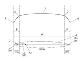
また、本実施形態では、爪形状検出部512は、印刷対象となる爪Tを上面視したときの爪幅(図4(a)において爪幅W)を検出する。図4(a)に示す例では、爪Tを上面視した場合に、爪Tの幅方向の端部が、指の爪床(爪と皮膚が密着している指先の皮膚)から離れる両側の端部A,B間の長さ(幅寸法)を爪幅Wとしている。
なお、爪Tのいかなる部分の幅寸法をもって爪幅Wとするかは、適宜設定可能であり、例えば、爪Tの幅方向において最も幅の広い部分の寸法を爪幅Wとしてもよい。
爪形状検出部512によって検出された結果である爪形状(爪Tの輪郭)及び爪幅Wは、記憶部52の爪形状メモリ523に記憶される。
In the present embodiment, the nail
It should be noted that it is possible to appropriately set which part of the nail T has the width dimension as the nail width W. For example, the dimension of the widest part in the width direction of the nail T may be the nail width W.
The nail shape (the contour of the nail T) and the nail width W, which are the results detected by the nail
印刷制御部513は、ネイルデザインの画像データに基づく印刷データを印刷部40の印刷ヘッド46に出力し、この印刷データにしたがって印刷ヘッド46により爪Tに印刷が施されるように印刷部40を制御する。
なお、印刷制御部513は、ネイルデザインの画像データに曲面補正を行って印刷データとすることが好ましい。
The
Note that the
本実施形態では、印刷制御部513は、爪形状検出部512により検出された爪幅Wと記憶部52のパラメータメモリ524に記憶されているパラメータ(図3(b)参照)とに基づいて、印刷対象となる爪Tについて大液滴インクにより印刷すべき大液滴印刷幅P(すなわち、大液滴インクにより印刷すべき範囲の爪Tの幅方向における幅寸法)を取得し、当該爪Tの幅方向の両端部から中央部に向かって大液滴印刷幅Pまでの領域では印刷ヘッド46より大液滴インクを噴射させて、大液滴インクにより印刷し、それ以外の領域では印刷ヘッド46より小液滴インクを噴射させて、小液滴インクにより印刷するように印刷ヘッド46を制御する。
In the present embodiment, the
ここで、大液滴インクとは着弾径がおよそφ40μm以上のインク液滴であり、小液滴インクとは着弾径がおよそφ30μm以下のインク液滴を意味する。
小液滴インクは、飛翔距離が5mm程度までであれば印刷対象の所望の位置にほぼ正確に着弾するが、飛翔距離が5mmを超えると所望の位置に正確に着弾させることが難しくなり、画質が著しく悪化する。これに対して、小液滴インクよりも液滴量の多い大液滴インクであれば、飛翔距離が5mmを超えても所望の位置にほぼ正確に着弾させることができる。
図4(b)は、図4(a)における矢視b方向から爪を見た図である。
図4(b)に示すように、印刷対象である爪Tは、幅方向の中央部の高さが高く、両端部では高さが低くなる曲面形状となっている。このため、爪Tの幅方向の中央部では、印刷ヘッド46と爪Tの表面との距離が近いが、爪Tの幅方向の両端部では、印刷ヘッド46と爪Tの表面との距離が遠くなってしまう。
例えば、ネイルプリント装置1の場合、印刷ヘッド46から爪Tの中央部までの距離を2mmに設定した場合には、印刷ヘッド46から爪Tの端部までの距離は5mm〜8mm程度となる。このため、爪Tの端部付近では、小液滴インクでは正確な着弾が難しいが、大液滴インクであれば、所望の位置にほぼ正確に着弾させることができる。
Here, the large droplet ink is an ink droplet having a landing diameter of approximately 40 μm or more, and the small droplet ink is an ink droplet having a landing diameter of approximately 30 μm or less.
Small droplet ink will land almost accurately on the desired position of the print target if the flying distance is up to about 5 mm, but if the flying distance exceeds 5 mm, it will be difficult to land accurately on the desired position. Is significantly worse. On the other hand, a large droplet ink having a larger amount of droplets than a small droplet ink can be landed almost accurately at a desired position even if the flight distance exceeds 5 mm.
FIG.4 (b) is the figure which looked at the nail | claw from the arrow b direction in Fig.4 (a).
As shown in FIG. 4B, the nail T to be printed has a curved shape in which the height of the central portion in the width direction is high and the height is low at both ends. For this reason, the distance between the
For example, in the case of the
そこで、本実施形態では、印刷制御部513は、爪幅Wと記憶部52のパラメータとに基づいて、大液滴インクにより印刷すべき大液滴印刷幅Pを取得し、爪Tの幅方向の両端部については、この大液滴印刷幅Pの領域だけ大液滴インクにより印刷するように印刷ヘッド46を制御する。
例えば、爪幅Wに対する大液滴印刷幅Pの割合を示すパラメータが、図3(b)に示すように10であった場合、図5に示すように、爪幅W100%のうち、爪Tの幅方向の左右の端部10%ずつを大液滴インクにより印刷すべき大液滴印刷幅Pとする。この場合、例えば爪幅が15mmであれば、爪Tの幅方向の左右の端部から中央に向かって1.5mmずつの幅の領域を大液滴インクにより印刷し、その他の領域を小液滴インクで印刷する。
一般に、爪Tは、幅方向の左右の端部10%程度の部分(すなわち、図4(b)及び図5において、点Cから端部Aまでの間と、点Dから端部Bまでの間)において、比較的大きく高さが変化しており、この部分のみを大液滴インクにより印刷し、他の部分については小液滴インクにより印刷することにより、爪Tの中央部及びその近傍では、きめの細かい高精細な印刷を可能とするとともに、爪の両端部及びその近傍については、確実にインクを着弾させ、インク濃度の低下等による画質の低下を最低限に抑えることができる。
Therefore, in the present embodiment, the
For example, when the parameter indicating the ratio of the large droplet printing width P to the nail width W is 10 as shown in FIG. 3B, as shown in FIG. A large droplet printing width P to be printed with large droplet ink is set to 10% each of the left and right end portions in the width direction. In this case, for example, if the width of the nail is 15 mm, an area having a width of 1.5 mm from the left and right ends in the width direction of the nail T toward the center is printed with a large droplet ink, and the other areas are small liquid. Print with drops of ink.
In general, the claw T is a portion of about 10% of the left and right end portions in the width direction (that is, between the point C and the end portion A and between the point D and the end portion B in FIGS. 4B and 5). The height of the nail T is relatively large, and only this portion is printed with the large droplet ink, and the other portion is printed with the small droplet ink. Then, fine high-definition printing can be performed, and ink is surely landed at both ends of the nail and the vicinity thereof, so that a decrease in image quality due to a decrease in ink density or the like can be minimized.
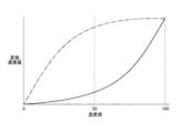
さらに、印刷制御部513は、大液滴インクと小液滴インクの各々で印刷したときの濃度が同じになるように、それぞれに適正なガンマ補正テーブルを有する。ガンマ補正テーブルは、印刷したい画像の濃度値をインク液滴に応じて変換したものである。
図6は、ガンマ補正テーブルの一例を示す図である。
図6において、大液滴インクの変換濃度値を実線で示し、小液滴インクの変換濃度値を一点鎖線で示している。
例えば、小液滴インクを3滴噴射させた場合と、大液滴インクを3滴噴射させた場合とでは、大液滴インクを3滴噴射させた場合の方が爪Tに着弾するインクの量が増えて色が濃くなってしまう。特にネイルデザインの画像データについて曲面補正を行った場合には、爪Tの両端部におけるインクの量が多くなっているため、より一層爪Tの両端部におけるインク濃度が濃くなる。このため、大液滴インク用の濃度変換テーブルと小液滴インク用の濃度変換テーブルとを持ち、これによって濃度値をインク液滴に応じて変換して、噴射するインク液滴の数を変換濃度値に応じた数に制御して印刷を行う。すなわち、大液滴インクについては実線で示した変換濃度値にしたがった数のインク液滴で印刷し、小液滴インクについては一点鎖線で示した変換濃度値にしたがった数のインク液滴で印刷する。これにより、全体的に濃度の揃った綺麗な印刷を行うことができる。
Further, the
FIG. 6 is a diagram illustrating an example of a gamma correction table.
In FIG. 6, the conversion density value of the large droplet ink is indicated by a solid line, and the conversion density value of the small droplet ink is indicated by a one-dot chain line.
For example, when three droplets of small droplet ink are ejected and when three droplets of large droplet ink are ejected, the case where three droplets of large droplet ink are ejected is the ink that lands on the nail T. The amount increases and the color becomes darker. In particular, when curved surface correction is performed on nail design image data, the amount of ink at both ends of the nail T is increased, so that the ink density at both ends of the nail T is further increased. Therefore, it has a density conversion table for large droplet inks and a density conversion table for small droplet inks, which converts the density value according to the ink droplets and converts the number of ejected ink droplets. Printing is performed by controlling the number according to the density value. That is, printing is performed with the number of ink droplets according to the conversion density value indicated by the solid line for the large droplet ink, and the number of ink droplets according to the conversion density value indicated by the alternate long and short dash line for the small droplet ink. Print. As a result, it is possible to perform clean printing with a uniform density as a whole.
表示制御部514は、表示部13を制御して、各種の表示画面を表示させるものである。
本実施形態では、表示制御部514は、例えば、印刷指U1を撮影して得られた爪画像や、爪Tに印刷すべき画像(すなわち、「ネイルデザイン」)を選択するためのデザイン選択画面、デザイン確認用のサムネイル画像、各種の指示を表示させる指示画面等を表示部13に表示させるようになっている。
The
In the present embodiment, the
次に、図7等を参照しつつ、本実施形態におけるネイルプリント装置1による印刷方法について説明する。
このネイルプリント装置1により印刷を行う場合、ユーザはまず、電源スイッチを入れて制御装置50を起動させる。
表示制御部514は、表示部13にデザイン選択画面を表示させ、ユーザは操作部12の操作釦121等を操作して、デザイン選択画面に表示された複数のネイルデザインの中から所望のネイルデザインを選択することにより、操作部12から選択指示信号が出力されて、一つのネイルデザインが選定される。
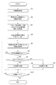
次に、図2に示すように、ユーザが印刷指U1を印刷指挿入部20a内に挿入し、印刷指U1のセットが完了すると、撮影制御部511が撮影部30を制御して印刷指U1の爪Tを撮影させ、爪画像を取得する(ステップS1)。爪画像が取得されると、爪形状検出部512は、当該爪画像から爪形状(爪Tの輪郭)の他、爪幅Wを検出する(ステップS2)。
爪幅Wが検出されると、印刷制御部513は、パラメータメモリ524からパラメータを読み出してこれを参照し、爪幅Wに対応する大液滴印刷割合α(図3(b)では、10)を取得する(ステップS3)。そして、このパラメータと爪幅Wから大液滴インクで印刷すべき範囲の幅である大液滴印刷幅Pを算出する(ステップS4)。すなわち、大液滴印刷割合αが10である場合、P=W×10/100となり、例えば、爪幅Wが20mmであれば、大液滴印刷幅Pは2mmとなる。
印刷制御部513は、ネイルデザインの画像データについて、印刷対象となる爪Tの爪形状に合わせ込む合わせ込み処理を行うとともに、曲面補正、ガンマ補正テーブルを用いた濃度値補正等を行い、補正後の画像データにしたがって爪Tに印刷を施すように印刷ヘッド46を制御する。
このとき、爪Tの幅方向の一方側の端部(印刷初期位置)から他方側の端部に向かって印刷ヘッド46を移動させながら印刷動作が行われ、印刷制御部513は、随時、印刷位置(図5において3つの印刷位置D1〜D3を黒点で例示する)の、印刷初期位置(爪端部)からの距離dを取得する(ステップS5)。そして、印刷制御部513は、取得した距離dから、印刷位置が爪Tの印刷範囲内か否か(すなわち、爪Tの輪郭の内側か否か)を判断する(ステップS6)。印刷位置が印刷範囲内であると判断すると(ステップS6;YES)、印刷制御部513は、それが大液滴インクで印刷すべき範囲内か否かを判断する(ステップS7)。具体的には、d<Pであるか、d>W−Pである場合には、印刷位置が大液滴インクで印刷すべき範囲内であると判断(ステップS7;YES)し、それ以外の場合には印刷位置が大液滴インクで印刷すべき範囲内でないと判断(ステップS7;NO、すなわち、小液滴インクにより印刷範囲内と判断)する。
すなわち、例えば、爪幅Wが20mmであり、大液滴印刷幅Pが2mmである場合、図5における印刷初期位置(爪端部)からの距離d(d1)が、d1<P(例えば、1.8mm)である印刷位置D1は、大液滴インクで印刷すべき範囲内であると判断される。また、図5における印刷初期位置(爪端部)からの距離d(d2)が、d2>P(例えば、5mm)である印刷位置D2は、小液滴インクで印刷すべき範囲内であると判断される。また、図5における印刷初期位置(爪端部)からの距離d(d3)が、d3>W−P(例えば、19.3mm)である印刷位置D3は、大液滴インクで印刷すべき範囲内であると判断される。
印刷位置が大液滴インクで印刷すべき範囲内であると判断された場合(ステップS7;YES)には、印刷制御部513は、大液滴インクで印刷するように印刷ヘッド46を制御する(ステップS8)。また、印刷位置が大液滴インクで印刷すべき範囲内でないと判断(すなわち、小液滴インクにより印刷範囲内と判断)された場合(ステップS7;NO)には、印刷制御部513は、小液滴インクで印刷するように印刷ヘッド46を制御する(ステップS9)。
大液滴インクによる印刷又は小液滴インクによる印刷が行われた場合(ステップS8又はステップS9)、若しくは印刷位置が爪Tの印刷範囲内でない場合(ステップS6;NO)には、印刷制御部513は、当該爪Tについて印刷が終了したか否かを判断し(ステップS10)、印刷が終了していないと判断する場合(ステップS10;NO)には、ステップS5に戻って処理を繰り返す。他方、当該爪Tについて印刷が終了したと判断する場合(ステップS10;YES)には、印刷制御部513は、印刷処理を終了する。
なお、他にも印刷する指の爪Tがある場合には、印刷指U1を入れ替えて、上記の処理を繰り返す。
また、印刷が完了した爪Tを見て、ユーザが大液滴インクで印刷すべき大液滴印刷幅Pを変更したい場合には、操作部12を操作することにより、パラメータを変更・調整することができる。すなわち、例えば、粒状感の目立つ範囲が広すぎると感じる場合には、大液滴印刷幅Pを狭くする(小液滴インクによってきめ細かく印刷する範囲を広くする)方向にパラメータを修正し、端部にインクが十分に付着していない、色の薄い部分があると感じる場合には、大液滴印刷幅Pを広くする(小液滴インクによってきめ細かく印刷する範囲を狭くする)方向にパラメータを修正する。一旦修正されたパラメータは修正後の状態でパラメータメモリ524に記憶され、次回以降の印刷の際には、この修正後のパラメータが参照される。
Next, a printing method by the
When printing is performed by the
The
Next, as shown in FIG. 2, when the user inserts the printing finger U1 into the printing
When the nail width W is detected, the
The
At this time, a printing operation is performed while moving the
That is, for example, when the nail width W is 20 mm and the large droplet printing width P is 2 mm, the distance d (d1) from the initial printing position (nail end) in FIG. 5 is d1 <P (for example, 1.8 mm) is determined to be within the range to be printed with large ink droplets. Further, the printing position D2 in which the distance d (d2) from the initial printing position (nail end) in FIG. 5 is d2> P (for example, 5 mm) is within the range to be printed with the small droplet ink. To be judged. In addition, the printing position D3 in which the distance d (d3) from the initial printing position (nail end) in FIG. 5 is d3> WP (for example, 19.3 mm) is a range to be printed with large droplet ink. Is determined to be within.
If it is determined that the printing position is within the range to be printed with the large droplet ink (step S7; YES), the
When printing with large droplet ink or printing with small droplet ink is performed (step S8 or step S9), or when the printing position is not within the printing range of the nail T (step S6; NO), the print control unit In step S513, it is determined whether printing has been completed for the nail T (step S10). If it is determined that printing has not been completed (step S10; NO), the process returns to step S5 and the process is repeated. On the other hand, when it is determined that printing has been completed for the nail T (step S10; YES), the
If there are other finger nails T to be printed, the printing finger U1 is replaced and the above process is repeated.
When the user wants to change the large droplet printing width P to be printed with the large droplet ink by looking at the nail T after the printing is completed, the parameter is changed / adjusted by operating the
以上のように、本実施形態によれば、印刷対象となる爪Tを上面視したときの爪幅Wを検出し、爪幅Wと、爪幅Wに対する大液滴印刷幅Pを規定するパラメータとに応じて、小液滴インクよりも液滴量の多い大液滴インクにより印刷すべき大液滴印刷幅Pを決定し、爪Tの幅方向の両端部から中央部に向かって大液滴印刷幅Pだけ大液滴インクにより印刷し、それ以外の部分を小液滴インクにより印刷する。このため、印刷ヘッド46からの距離が近く、小液滴インクでも正確に着弾させることのできる爪Tの中央部については、小液滴インクによってきめ細かい高精細な印刷を行うとともに、印刷ヘッド46からの距離が遠い部分である爪Tの幅方向の両端部にもインクを確実に着弾させて、デザインと濃度の乱れをなくし、画質の低下を最低限に抑えることができる。このように爪Tの中央部と端部とで液滴量の異なるインクを使い分けることにより、最も目立つ部分である爪Tの中央部においては粒状感の無い高精細な仕上がりを実現でき、爪T全体としても濃度むら等が抑えられるため、全ての領域において綺麗な仕上がりの高品位のネイルプリントを実現することができる。
また、本実施形態では、単にカメラ32によって取得した画像から爪Tを上面視したときの爪幅Wを検出し、この爪幅Wと予め記憶されているパラメータとに基づいて、大液滴インクにより印刷すべき大液滴印刷幅Pを決定するという手法を用いている。このため、印刷ヘッド46から爪Tの表面までの距離を測定する必要等がなく、別途センサ等を設ける必要もないため、簡易で安価な装置構成により、高精細な印刷を実現することができる。
また、本実施形態では、爪幅Wに対する大液滴印刷幅Pの割合を示す数値をパラメータとしている。このため、1つのパラメータで各種の爪幅Wの爪Tに対応させることができ、パラメータメモリ524のデータ量を少なくすることができる。
さらに本実施形態では、入力指示可能な操作部12を備え、操作部12からの入力指示に応じて、パラメータを変更可能となっている。このため、小液滴インクによるきめ細かい印刷を行う部分と大液滴インクにより爪T表面に確実にインクを着弾させる部分とのバランスをユーザが自在に修正、調整することができ、ユーザの好みに応じた仕上がりのネイルプリントを実現することができる。
As described above, according to the present embodiment, the nail width W when the nail T to be printed is viewed from above is detected, and the nail width W and the parameter that defines the large droplet printing width P with respect to the nail width W are defined. Accordingly, the large droplet printing width P to be printed by the large droplet ink having a larger droplet amount than that of the small droplet ink is determined, and the large liquid is directed from both ends in the width direction of the nail T toward the central portion. Printing is performed with the large droplet ink for the droplet printing width P, and the other portions are printed with the small droplet ink. For this reason, at the central portion of the nail T that is close to the
In this embodiment, the nail width W when the nail T is viewed from the top is simply detected from the image acquired by the
In the present embodiment, a numerical value indicating the ratio of the large droplet printing width P to the nail width W is used as a parameter. For this reason, it is possible to correspond to the claws T having various claw widths W with one parameter, and the amount of data in the
Further, in the present embodiment, an
なお、以上本発明の実施形態について説明したが、本発明は、かかる実施形態に限定されず、その要旨を逸脱しない範囲で、種々変形が可能であることは言うまでもない。 Although the embodiments of the present invention have been described above, the present invention is not limited to such embodiments, and various modifications can be made without departing from the scope of the present invention.
例えば、本実施形態では、パラメータとしての大液滴印刷割合が1種類だけパラメータメモリ524に記憶されている場合を例示したが、パラメータメモリ524に記憶されるパラメータは1種類に限定されない。
例えば、爪Tを形状によって複数のパターンに分類し、当該パターンごとに異なるパラメータを用意してもよい。爪Tをパターン分類する手法としては、例えば、図8(a)に示すように、照明灯33により爪Tに斜め上方向から光を照射した状態で、爪Tをカメラ32で撮影し、爪Tの端部に生じる影Sの形状や拡がり具合からおよその曲率等を推定して、予め用意されている複数のパターンのうち、最も近いパターンに爪Tを分類する。
図8(a)に示す例では、爪Taが最も中央部の盛り上がりの大きな爪であり、爪Tcは全体が比較的平坦な爪であり、爪Tbは、爪Taと爪Tcとの中間的な形状の爪となっている。この場合、例えば爪TaをパターンA、爪TbをパターンB、爪TcをパターンCにそれぞれ分類する。パラメータメモリ524には、例えば図8(b)に示すように、パターンA、パターンB、パターンCごとにそれぞれ異なるパラメータを用意しておき、爪Tがパターン分類されると、印刷制御部513は、当該パターンに対応したパラメータを適用して大液滴印刷幅を設定する。例えば、最も盛り上がりの大きなパターンAに分類された爪Taについては大液滴印刷割合15を適用し、爪幅を100%としたときに、爪Tの幅方向の15%ずつの幅の領域を大液滴インクによって印刷する。また、全体が平坦であるパターンCに分類された爪Tcについては大液滴印刷割合5を適用し、爪幅を100%としたときに、爪Tの幅方向の5%ずつの幅の領域を大液滴インクによって印刷する。
なお、爪Tのパターン分類は、制御部51によって自動的に行われる場合に限定されず、例えば、ユーザやネイルサロンのスタッフ等が印刷対象となる爪Tに合うと思われるパターンを選択して、当該パターンに対応したパラメータを用いるよう、操作部12等から入力指示してもよい。
このように、爪Tをパターン部類し、パターンごとに異なるパラメータを適用することにより、爪Tごとの形状に応じたより適切な大液滴印刷幅を設定することが可能となる。
For example, in this embodiment, the case where only one type of large droplet printing ratio as a parameter is stored in the
For example, the nail T may be classified into a plurality of patterns depending on the shape, and different parameters may be prepared for each pattern. As a method for classifying the nail T, for example, as shown in FIG. 8A, the nail T is photographed with the
In the example shown in FIG. 8A, the nail Ta is the nail with the largest bulge in the center, the nail Tc is a relatively flat nail as a whole, and the nail Tb is an intermediate between the nail Ta and the nail Tc. The nails have a unique shape. In this case, for example, the nail Ta is classified as the pattern A, the nail Tb is classified as the pattern B, and the nail Tc is classified as the pattern C. In the
Note that the pattern classification of the nail T is not limited to the case where it is automatically performed by the
As described above, by classifying the nail T into patterns and applying different parameters for each pattern, it is possible to set a more appropriate large droplet printing width according to the shape of each nail T.
また、パラメータメモリ524に記憶されるパラメータは、指の種類に応じて複数用意されていてもよい。
図9(a)は、左右の手の小指から親指までそれぞれについてパラメータを設定した例を示している。
例えば、図9(a)に示した例では、左手小指及び右手小指については大液滴印刷割合5を適用し、左手親指及び右手親指については大液滴印刷割合15を適用し、その他の指については、大液滴印刷割合10を適用するようにパラメータが設定されている。
図9(a)に示したパラメータを用いて大液滴印刷幅を設定した場合には、左手小指及び右手小指については、図9(b)に示すように、爪幅Wを100%とした場合における爪Tの端部0%から5%まで及び95%から100%までが大液滴インクで印刷すべき大液滴印刷幅Pとなる。また、左手親指及び右手親指については、図9(d)に示すように、爪幅Wを100%とした場合における爪Tの端部0%から15%まで及び85%から100%までが大液滴インクで印刷すべき大液滴印刷幅Pとなる。また、それ以外の指については、図9(c)に示すように、爪幅Wを100%とした場合における爪Tの端部0%から10%まで及び90%から100%までが大液滴インクで印刷すべき大液滴印刷幅Pとなる。
爪幅や爪Tの曲がり具合は、親指であれば比較的大きく、小指であれば比較的小さいというように、指の種類によって異なる場合が多いところ、図9(a)に示すように、指の種類に応じて複数のパラメータを用意した場合には、指の種類に応じた適切な大液滴印刷幅を設定することが可能となる。また、印刷する際に指の種類を選択するだけで印刷対象となる爪Tに適したパラメータが設定されるため、より適切な大液滴印刷幅を簡易迅速に設定することができる。
A plurality of parameters stored in the
FIG. 9A shows an example in which parameters are set for the left and right hands from the little finger to the thumb.
For example, in the example shown in FIG. 9A, the large
When the large droplet printing width is set using the parameters shown in FIG. 9A, the nail width W is set to 100% for the left and right little fingers as shown in FIG. 9B. In this case, the end portion of the nail T is 0% to 5% and 95% to 100% is the large droplet printing width P to be printed with the large droplet ink. As for the left thumb and right thumb, as shown in FIG. 9D, when the nail width W is 100%, the end of the nail T is 0% to 15% and 85% to 100%. A large droplet printing width P to be printed with droplet ink is obtained. For other fingers, as shown in FIG. 9 (c), when the nail width W is 100%, the end portions of the nail T are 0% to 10% and 90% to 100% are large liquids. The large droplet printing width P to be printed with droplet ink is obtained.
The fingernail width and the degree of bending of the fingernail T are often different depending on the type of finger, such as being relatively large for the thumb and relatively small for the little finger. As shown in FIG. In the case where a plurality of parameters are prepared according to the type, it is possible to set an appropriate large droplet printing width according to the type of the finger. In addition, since a parameter suitable for the nail T to be printed is set simply by selecting a finger type when printing, a more appropriate large droplet printing width can be set easily and quickly.
また、本実施形態では、大液滴印刷幅の爪幅Wに対する割合を示す数値がパラメータとしてパラメータメモリ524に記憶されている場合を例示したが、パラメータメモリ524に記憶されているパラメータは、爪幅Wに対する大液滴印刷幅を規定するものであればどのような形式のものでもよく、大液滴印刷幅の爪幅Wに対する割合を示す数値に限定されない。
例えば、図10に示すように、複数の互いに異なる爪幅Wごとに、大液滴印刷幅Pの具体的数値を対応付けたものをパラメータとして記憶するパラメータメモリ525を備えてもよい。このように、大液滴印刷幅Pの具体的数値をパラメータとする場合に、検出された爪幅Wがパラメータメモリ525に規定されている複数の爪幅Wの何れかに合致する場合には、制御部51は合致する爪幅Wに対応する数値を読み出してくれば足りるため、大液滴印刷幅の爪幅Wに対する割合を示す数値をパラメータとする場合と比べて演算処理の時間等を省くことができる。また、検出された爪幅Wがパラメータメモリ525に規定されている複数の爪幅Wに合致しない場合には、パラメータメモリ525に規定されている複数の爪幅Wにおける検出された爪幅Wに最も近似する爪幅Wに対応する数値を大液滴印刷幅として読み出すようにしてもよいし、パラメータメモリ525に規定されている爪幅Wに対する値を各爪幅Wと検出された爪幅Wとの差分に応じて比例計算して、算出された値を大液滴印刷幅とするようにしてもよい。
In the present embodiment, the numerical value indicating the ratio of the large droplet printing width to the nail width W is exemplified as being stored in the
For example, as shown in FIG. 10, a
また、本実施形態では、プログラムメモリ521、デザインデータメモリ522、爪形状メモリ523、パラメータメモリ524が制御装置50の記憶部52内に設けられている場合を例としたが、プログラムメモリ521、デザインデータメモリ522、爪形状メモリ523、パラメータメモリ524は制御装置50の記憶部52(ROM、RAM)に設けられている場合に限定されず、別途記憶部が設けられていてもよい。
In this embodiment, the case where the
また、本実施形態では、指を1本ずつ装置に挿入して順次印刷を行うネイルプリント装置1を例としたが、4本の指に対して同時に印刷を行うことのできる装置に本発明を適用することも可能である。
In the present embodiment, the
以上本発明のいくつかの実施形態を説明したが、本発明の範囲は、上述の実施の形態に限定するものではなく、特許請求の範囲に記載された発明の範囲とその均等の範囲を含む。
以下に、この出願の願書に最初に添付した特許請求の範囲に記載した発明を付記する。付記に記載した請求項の項番は、この出願の願書に最初に添付した特許請求の範囲の通りである。
〔付記〕
<請求項1>
小液滴インクと該小液滴インクよりも液滴量の多い大液滴インクとを選択的に噴射可能に構成された印刷ヘッドと、
印刷対象となる爪の幅方向の長さを爪幅として検出する爪形状検出部と、
前記爪幅における前記大液滴インクにより印刷すべき大液滴印刷幅を規定するパラメータを記憶している記憶部と、
前記爪形状検出部により検出された前記爪幅と前記記憶部に記憶されている前記パラメータとに基づいて前記印刷対象となる爪の前記大液滴印刷幅を取得し、前記印刷ヘッドを制御して、当該爪の幅方向の両端部から中央部に向かって前記大液滴印刷幅までの領域では前記印刷ヘッドから前記大液滴インクを噴射させ、それ以外の領域では前記印刷ヘッドから前記小液滴インクを噴射させる印刷制御部と、
を備えていることを特徴とするネイルプリント装置。
<請求項2>
前記記憶部に記憶されている前記パラメータは、前記爪幅に対する前記大液滴印刷幅の比率であり、
前記印刷制御部は、前記爪形状検出部により検出された前記爪幅に前記パラメータの値を乗算して、前記大液滴印刷幅を取得することを特徴とする請求項1に記載のネイルプリント装置。
<請求項3>
前記記憶部に記憶されている前記パラメータは、前記爪幅の複数の互いに異なる値の各々に対する前記大液滴印刷幅の値であり、
前記印刷制御部は、前記パラメータにおける前記爪形状検出部により検出された前記爪幅に対応する値を、前記大液滴印刷幅として取得することを特徴とする請求項1に記載のネイルプリント装置。
<請求項4>
前記パラメータは、親指、人差し指、中指、薬指及び小指の各々に対応して設定されていることを特徴とする請求項1から請求項3のいずれか一項に記載のネイルプリント装置。
<請求項5>
前記印刷制御部は、前記爪に印刷する画像の濃度を前記大液滴インクと前記小液滴インクの各々に応じた変換濃度値に変換したガンマ補正テーブルを有し、前記画像の印刷を施す際に、前記大液滴インクと前記小液滴インクのそれぞれのインク液滴の数を、前記変換濃度値にしたがった数に設定することを特徴とする請求項1から請求項4のいずれか一項に記載のネイルプリント装置。
<請求項6>
入力指示可能な操作部を備え、
前記操作部からの入力指示に応じて、前記パラメータを変更可能となっていることを特徴とする請求項1から請求項5のいずれか一項に記載のネイルプリント装置。
<請求項7>
印刷対象となる爪に画像の印刷を施すネイルプリント装置の印刷方法において、
前記ネイルプリント装置は、小液滴インクと該小液滴インクよりも液滴量の多い大液滴インクとを選択的に噴射可能に構成された印刷ヘッドと、印刷対象となる爪の爪幅における前記大液滴インクにより印刷すべき大液滴印刷幅を規定するパラメータを記憶している記憶部と、を有し、
前記印刷対象となる爪の幅方向の長さ爪幅として検出し、
検出された前記爪幅と前記記憶部に記憶されている前記パラメータとに基づいて大液滴印刷幅を取得し、
前記爪の幅方向の両端部から中央部に向かって前記大液滴印刷幅までの領域では前記印刷ヘッドから前記大液滴インクを噴射させて印刷を施し、それ以外の領域では前記印刷ヘッドから小液滴インクを噴射させて印刷を施すことを特徴とするネイルプリント装置の印刷方法。
<請求項8>
前記記憶部に記憶されている前記パラメータは、前記爪幅に対する前記大液滴印刷幅の比率であり、
前記爪形状検出部により検出された前記爪幅に前記パラメータの値を乗算して、前記大液滴印刷幅を取得することを特徴とする請求項7に記載のネイルプリント装置の印刷方法。
<請求項9>
前記記憶部に記憶されている前記パラメータは、前記爪幅の複数の互いに異なる値の各々に対する前記大液滴印刷幅の値であり、
前記パラメータにおける前記爪形状検出部により検出された前記爪幅に対応する値を、前記大液滴印刷幅として取得することを特徴とする請求項7に記載のネイルプリント装置の印刷方法。
<請求項10>
前記ネイルプリント装置は、前記爪に印刷する画像の濃度を前記大液滴インクと前記小液滴インクの各々に応じた変換濃度値に変換したガンマ補正テーブルを有し、
前記画像の印刷を施す際に、前記大液滴インクと前記小液滴インクのそれぞれのインク液滴の数を、前記変換濃度値にしたがった数に設定することを特徴とする請求項7から請求項9のいずれか一項に記載のネイルプリント装置の印刷方法。
Although several embodiments of the present invention have been described above, the scope of the present invention is not limited to the above-described embodiments, but includes the scope of the invention described in the claims and equivalents thereof. .
The invention described in the scope of claims attached to the application of this application will be added below. The item numbers of the claims described in the appendix are as set forth in the claims attached to the application of this application.
[Appendix]
<Claim 1>
A print head configured to selectively eject a small droplet ink and a large droplet ink having a larger droplet amount than the small droplet ink;
A nail shape detection unit for detecting the length in the width direction of the nail to be printed as a nail width;
A storage unit storing parameters defining a large droplet printing width to be printed by the large droplet ink in the nail width;
Based on the nail width detected by the nail shape detection unit and the parameters stored in the storage unit, the large droplet printing width of the nail to be printed is acquired, and the print head is controlled. Thus, the large droplet ink is ejected from the print head in the region from the both end portions in the width direction of the nail toward the central portion, and the small droplet ink is ejected from the print head in the other regions. A print control unit for ejecting droplet ink;
A nail printing apparatus comprising:
<Claim 2>
The parameter stored in the storage unit is a ratio of the large droplet printing width to the nail width,
2. The nail print according to
<Claim 3>
The parameter stored in the storage unit is a value of the large droplet printing width for each of a plurality of different values of the nail width,
2. The nail printing apparatus according to
<Claim 4>
The nail print apparatus according to any one of
<Claim 5>
The print control unit has a gamma correction table in which the density of an image printed on the nail is converted into a converted density value corresponding to each of the large droplet ink and the small droplet ink, and prints the image In this case, the number of ink droplets of each of the large droplet ink and the small droplet ink is set to a number according to the converted density value. The nail printing apparatus according to one item.
<Claim 6>
It has an operation unit that can input instructions,
The nail print apparatus according to any one of
<Claim 7>
In a printing method of a nail printing apparatus that prints an image on a nail to be printed,
The nail printing apparatus includes a print head configured to selectively eject a small droplet ink and a large droplet ink having a larger droplet amount than the small droplet ink, and a nail width of a nail to be printed. A storage unit storing parameters defining a large droplet printing width to be printed with the large droplet ink in
Detected as the length nail width in the width direction of the nail to be printed,
Obtaining a large droplet printing width based on the detected nail width and the parameter stored in the storage unit;
Printing is performed by ejecting the large droplet ink from the print head in the region from the both ends in the width direction of the nail to the large droplet printing width toward the center portion, and from the print head in other regions. A printing method for a nail printing apparatus, wherein printing is performed by ejecting small droplet ink.
<Claim 8>
The parameter stored in the storage unit is a ratio of the large droplet printing width to the nail width,
The printing method of the nail printing apparatus according to claim 7, wherein the large droplet printing width is obtained by multiplying the nail width detected by the nail shape detection unit by the value of the parameter.
<Claim 9>
The parameter stored in the storage unit is a value of the large droplet printing width for each of a plurality of different values of the nail width,
The printing method of the nail print apparatus according to claim 7, wherein a value corresponding to the nail width detected by the nail shape detection unit in the parameter is acquired as the large droplet printing width.
<Claim 10>
The nail printing apparatus has a gamma correction table in which the density of an image printed on the nail is converted into a converted density value corresponding to each of the large droplet ink and the small droplet ink,
The number of ink droplets of each of the large droplet ink and the small droplet ink is set to a number according to the converted density value when the image is printed. The printing method of the nail print apparatus as described in any one of
1 ネイルプリント装置
20a 印刷指挿入部
30 撮影部
32 カメラ
40 印刷部
46 印刷ヘッド
50 制御装置
51 制御部
52 記憶部
511 撮影制御部
512 爪形状検出部
513 印刷制御部
523 爪形状メモリ
524 パラメータメモリ
T 爪
U1 印刷指
DESCRIPTION OF
Claims (11)
印刷対象となる爪の幅方向の長さを爪幅として検出する爪形状検出部と、
前記爪幅に基づいて前記爪における前記大液滴インクにより印刷すべき大液滴印刷幅を取得し、当該爪の幅方向の両端部から前記爪の前記幅方向の中央部に向かって前記大液滴印刷幅までの端部領域では、前記爪の幅方向における位置によらず前記印刷ヘッドから前記第2液滴量を有する前記大液滴インクを噴射させ、前記爪における前記端部領域以外の領域では、前記爪の幅方向における位置によらず前記印刷ヘッドから前記第1液滴量を有する前記小液滴インクを噴射させるように前記印刷ヘッドを制御する印刷制御部と、
を備えていることを特徴とするネイルプリント装置。 A large droplet ink and selectively injectable configured print head having a second drop volume droplet amount is larger than the first droplet amount and droplets ink having a first drop volume ,
A nail shape detection unit for detecting the length in the width direction of the nail to be printed as a nail width;
Based on the nail width, a large droplet printing width to be printed by the large droplet ink on the nail is obtained, and the large size of the nail from the both ends in the width direction of the nail toward the central portion in the width direction of the nail. In the end region up to the droplet printing width, the large droplet ink having the second droplet amount is ejected from the print head regardless of the position in the width direction of the nail, and other than the end region in the nail A print control unit that controls the print head to eject the small droplet ink having the first droplet amount from the print head regardless of the position in the width direction of the nail ;
A nail printing apparatus comprising:
前記印刷制御部は、前記爪幅と前記パラメータとに基づいて前記大液滴印刷幅を取得することを特徴とする請求項1に記載のネイルプリント装置。 A storage unit storing parameters defining the large droplet printing width in the nail width;
The nail printing apparatus according to claim 1, wherein the printing control unit acquires the large droplet printing width based on the nail width and the parameter.
前記印刷制御部は、前記爪形状検出部により検出された前記爪幅に前記パラメータの値を乗算して、前記大液滴印刷幅を取得することを特徴とする請求項2に記載のネイルプリント装置。 The parameter stored in the storage unit is a ratio of the large droplet printing width to the nail width,
3. The nail print according to claim 2, wherein the printing control unit obtains the large droplet printing width by multiplying the nail width detected by the nail shape detection unit by the value of the parameter. apparatus.
前記印刷制御部は、前記パラメータにおける前記爪形状検出部により検出された前記爪幅に対応する値を、前記大液滴印刷幅として取得することを特徴とする請求項2に記載のネイルプリント装置。 The parameter stored in the storage unit is a value of the large droplet printing width for each of a plurality of different values of the nail width,
The nail printing apparatus according to claim 2, wherein the print control unit acquires a value corresponding to the nail width detected by the nail shape detection unit in the parameter as the large droplet printing width. .
前記ネイルプリント装置は、第1液滴量を有する小液滴インクと前記第1液滴量よりも液滴量が多い第2液滴量を有する大液滴インクとを選択的に噴射可能に構成された印刷ヘッドを有し、
前記印刷対象となる爪の幅方向の長さ爪幅として検出し、
検出された前記爪幅に基づいて前記大液滴インクにより印刷すべき大液滴印刷幅を取得し、
前記爪の幅方向の両端部から前記爪の前記幅方向の中央部に向かって前記大液滴印刷幅までの端部領域では、前記爪の幅方向における位置によらず前記印刷ヘッドから前記第2液滴量を有する前記大液滴インクを噴射させて印刷を施し、前記爪における前記端部領域以外の領域では、前記爪の幅方向における位置によらず前記印刷ヘッドから前記第1液滴量を有する前記小液滴インクを噴射させて印刷を施すことを特徴とするネイルプリント装置の印刷方法。 In a printing method of a nail printing apparatus that prints an image on a nail to be printed,
The nail printing device selectively to be capable of injecting a large droplet ink having a second drop volume droplet amount is larger than the first droplet amount and droplets ink having a first drop volume Having a configured print head;
Detected as the length nail width in the width direction of the nail to be printed,
Obtaining a large droplet printing width to be printed with the large droplet ink based on the detected nail width;
Wherein the both end portions in the width direction of the nail toward the center in the width direction of the claw at an end region up to large droplet printing width, the from the print head regardless of the position in the width direction of the pawl first Printing is performed by ejecting the large droplet ink having the amount of two droplets, and in the region other than the end region in the nail, the first droplet from the print head regardless of the position in the width direction of the nail. A printing method for a nail printing apparatus, wherein printing is performed by ejecting the small droplet ink having a quantity .
前記爪幅と前記パラメータとに基づいて前記大液滴印刷幅を取得することを特徴とする請求項7に記載のネイルプリント装置の印刷方法。 The nail printing apparatus has a storage unit that stores parameters defining the large droplet printing width in the nail width,
The printing method of the nail printing apparatus according to claim 7, wherein the large droplet printing width is acquired based on the nail width and the parameter.
前記爪形状検出部により検出された前記爪幅に前記パラメータの値を乗算して、前記大液滴印刷幅を取得することを特徴とする請求項8に記載のネイルプリント装置の印刷方法。 The parameter stored in the storage unit is a ratio of the large droplet printing width to the nail width,
9. The printing method for a nail printing apparatus according to claim 8, wherein the large droplet printing width is obtained by multiplying the nail width detected by the nail shape detecting unit by the value of the parameter.
前記パラメータにおける前記爪形状検出部により検出された前記爪幅に対応する値を、前記大液滴印刷幅として取得することを特徴とする請求項8に記載のネイルプリント装置の印刷方法。 The parameter stored in the storage unit is a value of the large droplet printing width for each of a plurality of different values of the nail width,
The printing method of the nail printing apparatus according to claim 8, wherein a value corresponding to the nail width detected by the nail shape detection unit in the parameter is acquired as the large droplet printing width.
前記画像の印刷を施す際に、前記大液滴インクと前記小液滴インクのそれぞれのインク液滴の数を、前記変換濃度値にしたがった数に設定することを特徴とする請求項7から請求項10のいずれか一項に記載のネイルプリント装置の印刷方法。 The nail printing apparatus has a gamma correction table in which the density of an image printed on the nail is converted into a converted density value corresponding to each of the large droplet ink and the small droplet ink,
The number of ink droplets of each of the large droplet ink and the small droplet ink is set to a number according to the converted density value when the image is printed. The printing method of the nail print apparatus as described in any one of Claims 10.
Priority Applications (1)
| Application Number | Priority Date | Filing Date | Title |
|---|---|---|---|
| JP2013183566A JP6286952B2 (en) | 2013-09-05 | 2013-09-05 | Nail printing apparatus and printing method for nail printing apparatus |
Applications Claiming Priority (1)
| Application Number | Priority Date | Filing Date | Title |
|---|---|---|---|
| JP2013183566A JP6286952B2 (en) | 2013-09-05 | 2013-09-05 | Nail printing apparatus and printing method for nail printing apparatus |
Publications (3)
| Publication Number | Publication Date |
|---|---|
| JP2015047473A JP2015047473A (en) | 2015-03-16 |
| JP2015047473A5 JP2015047473A5 (en) | 2016-06-02 |
| JP6286952B2 true JP6286952B2 (en) | 2018-03-07 |
Family
ID=52697970
Family Applications (1)
| Application Number | Title | Priority Date | Filing Date |
|---|---|---|---|
| JP2013183566A Active JP6286952B2 (en) | 2013-09-05 | 2013-09-05 | Nail printing apparatus and printing method for nail printing apparatus |
Country Status (1)
| Country | Link |
|---|---|
| JP (1) | JP6286952B2 (en) |
Families Citing this family (7)
| Publication number | Priority date | Publication date | Assignee | Title |
|---|---|---|---|---|
| JP6547542B2 (en) * | 2015-09-18 | 2019-07-24 | カシオ計算機株式会社 | Nail shape acquisition device, drawing device, and control program for nail shape acquisition device |
| JP6666676B2 (en) * | 2015-09-30 | 2020-03-18 | 株式会社Screenホールディングス | Tablet printing apparatus and tablet printing method |
| CN205467967U (en) * | 2015-12-31 | 2016-08-17 | 郭伟 | Box structure of first beautiful colored drawing machine |
| JP6769365B2 (en) * | 2017-03-21 | 2020-10-14 | カシオ計算機株式会社 | Drawing device and drawing method |
| JP7022299B2 (en) | 2017-06-29 | 2022-02-18 | カシオ計算機株式会社 | Nail printing device and control method of nail printing device |
| JP7035394B2 (en) * | 2017-09-13 | 2022-03-15 | カシオ計算機株式会社 | Drawing device and drawing method |
| JP7206587B2 (en) * | 2017-12-08 | 2023-01-18 | カシオ計算機株式会社 | Rendering device and rendering method |
Family Cites Families (5)
| Publication number | Priority date | Publication date | Assignee | Title |
|---|---|---|---|---|
| JP3016147B1 (en) * | 1998-12-25 | 2000-03-06 | 株式会社アトラス | Nail art equipment |
| JP5732840B2 (en) * | 2010-12-14 | 2015-06-10 | カシオ計算機株式会社 | Nail printing apparatus and printing control method |
| JP5494562B2 (en) * | 2011-04-28 | 2014-05-14 | カシオ計算機株式会社 | Curved surface printing apparatus and printing control method for curved surface printing apparatus |
| JP5834472B2 (en) * | 2011-04-28 | 2015-12-24 | カシオ計算機株式会社 | Nail printing apparatus and printing control method |
| JP5402980B2 (en) * | 2011-05-09 | 2014-01-29 | カシオ計算機株式会社 | Nail printing apparatus and printing control method for nail printing apparatus |
-
2013
- 2013-09-05 JP JP2013183566A patent/JP6286952B2/en active Active
Also Published As
| Publication number | Publication date |
|---|---|
| JP2015047473A (en) | 2015-03-16 |
Similar Documents
| Publication | Publication Date | Title |
|---|---|---|
| JP6286952B2 (en) | Nail printing apparatus and printing method for nail printing apparatus | |
| JP5915571B2 (en) | Nail printing apparatus and printing method for nail printing apparatus | |
| JP6268827B2 (en) | Nail printing apparatus and printing method for nail printing apparatus | |
| US8919903B2 (en) | Nail printing device including printing head that performs printing on fingernail, and printing control method | |
| JP6439342B2 (en) | Nail information detection device, drawing device, and nail information detection method | |
| JP5141742B2 (en) | Nail printing apparatus and printing control method | |
| JP5853909B2 (en) | Nail printing apparatus and printing control method for nail printing apparatus | |
| JP6268771B2 (en) | Nail printing apparatus, printing method and program for nail printing apparatus | |
| JP5402980B2 (en) | Nail printing apparatus and printing control method for nail printing apparatus | |
| JP6128067B2 (en) | Drawing apparatus and drawing control method of drawing apparatus | |
| JP5831441B2 (en) | Nail printing apparatus and printing method for nail printing apparatus | |
| US10696067B2 (en) | Nail printing apparatus and control method | |
| US9463644B2 (en) | Drawing apparatus and drawing control method thereof | |
| US11517093B2 (en) | Drawing device and drawing method | |
| US20130077103A1 (en) | Color correction print apparatus and print control method | |
| JP2014124230A (en) | Nail printing device, and printing method for the same | |
| JP7035394B2 (en) | Drawing device and drawing method | |
| JP6390740B2 (en) | Drawing apparatus and drawing control method of drawing apparatus | |
| JP6048568B2 (en) | Nail printing apparatus and printing method for nail printing apparatus | |
| JP5435108B2 (en) | Nail printing apparatus and printing control method | |
| JP5928264B2 (en) | Nail printing apparatus and printing control method | |
| JP2022050736A (en) | Printer, printing method and program | |
| JP7294469B2 (en) | NAIL PRINTING DEVICE, CONTROL METHOD AND PROGRAM FOR NAIL PRINTING DEVICE | |
| JP6825244B2 (en) | Drawing device and drawing method of drawing device | |
| JP2013180154A (en) | Printing apparatus and printing control method |
Legal Events
| Date | Code | Title | Description |
|---|---|---|---|
| A521 | Written amendment |
Free format text: JAPANESE INTERMEDIATE CODE: A523 Effective date: 20160406 |
|
| A621 | Written request for application examination |
Free format text: JAPANESE INTERMEDIATE CODE: A621 Effective date: 20160406 |
|
| A131 | Notification of reasons for refusal |
Free format text: JAPANESE INTERMEDIATE CODE: A131 Effective date: 20170613 |
|
| A521 | Written amendment |
Free format text: JAPANESE INTERMEDIATE CODE: A523 Effective date: 20170814 |
|
| TRDD | Decision of grant or rejection written | ||
| A01 | Written decision to grant a patent or to grant a registration (utility model) |
Free format text: JAPANESE INTERMEDIATE CODE: A01 Effective date: 20180109 |
|
| A61 | First payment of annual fees (during grant procedure) |
Free format text: JAPANESE INTERMEDIATE CODE: A61 Effective date: 20180122 |
|
| R150 | Certificate of patent or registration of utility model |
Ref document number: 6286952 Country of ref document: JP Free format text: JAPANESE INTERMEDIATE CODE: R150 |