JP5728885B2 - Nail printing apparatus and printing control method - Google Patents
Nail printing apparatus and printing control method Download PDFInfo
- Publication number
- JP5728885B2 JP5728885B2 JP2010237106A JP2010237106A JP5728885B2 JP 5728885 B2 JP5728885 B2 JP 5728885B2 JP 2010237106 A JP2010237106 A JP 2010237106A JP 2010237106 A JP2010237106 A JP 2010237106A JP 5728885 B2 JP5728885 B2 JP 5728885B2
- Authority
- JP
- Japan
- Prior art keywords
- printing
- finger
- unit
- coordinate value
- contour line
- Prior art date
- Legal status (The legal status is an assumption and is not a legal conclusion. Google has not performed a legal analysis and makes no representation as to the accuracy of the status listed.)
- Active
Links
Images


Description
本発明は、ネイルプリント装置及び印刷制御方法に関するものである。 The present invention relates to a nail printing apparatus and a printing control method.
従来、指の爪に印刷を施すネイルプリント装置が提案されている(例えば、特許文献1参照)。ネイルプリント装置は、例えば、印刷しようとする爪の指を、装置本体に設けた指載置台に位置決めし、この位置決めした指の爪にインクジェット方式の印刷ヘッド等を用いて色や絵柄等の画像を印刷するプリント装置であるが、こうしたネイルプリント装置では、印刷中に指が動いて位置がずれたり指載置台から指が離れてしまったりすると絵柄等を正しく爪に印刷することができず、印刷エラーが生じてしまう。 Conventionally, a nail printing apparatus that prints on a fingernail has been proposed (see, for example, Patent Document 1). The nail printing apparatus, for example, positions a finger of a nail to be printed on a finger placing table provided in the apparatus main body, and uses an ink jet print head or the like on the finger nail thus positioned to print an image such as a color or a pattern. However, in such a nail printing device, if the finger moves during printing and the position is shifted or the finger is removed from the finger placement table, the pattern or the like cannot be correctly printed on the nail, A printing error occurs.
印刷対象となる記録媒体が紙等である場合には、位置ずれ等が生じて印刷エラーが生じた場合には、当該紙等を廃棄して再印刷を行えばよい。
しかし、印刷対象が爪である場合には、印刷途中で位置ずれ等が生じた場合、一旦爪上に付着したインクを除去した上で再印刷を行う必要があり、その手間や時間等がユーザにとって煩わしいという問題がある。
When the recording medium to be printed is paper or the like, if a printing error occurs due to misalignment or the like, the paper or the like may be discarded and reprinted.
However, when the object to be printed is a nail, if there is a misalignment in the middle of printing, it is necessary to remove the ink that has adhered to the nail and then perform reprinting. There is a problem that it is troublesome.
そこで、このような装置においては、指固定治具を設けて、印刷中に指が動かないように指固定治具等によって指を固定した状態で印刷を行うことが考えられる。
このように指を固定すれば、印刷中に指の位置がずれたり指載置台から指が離れてしまったりすることがなく、適切な位置に正しく印刷を行うことが可能となる。
Therefore, in such an apparatus, it is conceivable to perform printing in a state where a finger fixing jig is provided and the finger is fixed by a finger fixing jig or the like so that the finger does not move during printing.
If the finger is fixed in this way, the position of the finger is not shifted during printing or the finger is not separated from the finger placement table, and printing can be performed correctly at an appropriate position.
しかしながら、指固定治具等によって指を固定した状態で印刷を行うと、印刷している間、指が圧迫された状態となることから、ユーザにとって極めて不快である。
また、ユーザが印刷する指に指輪等の装飾品をつけている場合には、指固定治具等によってしっかりと指を固定することが困難な場合がある等の問題もある。
However, if printing is performed with a finger fixed by a finger fixing jig or the like, the finger is pressed during printing, which is extremely uncomfortable for the user.
In addition, when a user wears a decorative item such as a ring on a finger to be printed, there is a problem that it may be difficult to firmly fix the finger with a finger fixing jig or the like.
本発明は以上のような事情に鑑みてなされたものであり、印刷中に指が動いて指の位置がずれたり指載置台から指が離れてしまったりした場合、不適切な位置に誤って印刷されてしまう事態を未然に防止することのできるネイルプリント装置及び印刷制御方法を提供することを目的とするものである。 The present invention has been made in view of the circumstances as described above, and when a finger moves during printing and the position of the finger is shifted or the finger is separated from the finger placement table, the position is mistakenly set to an inappropriate position. An object of the present invention is to provide a nail printing apparatus and a printing control method that can prevent a situation in which printing is performed.
前記課題を解決するために、請求項1に記載のネイルプリント装置は、
指が載置される指載置手段と、
この指載置手段上に載置された指を撮影して指爪画像を得る撮影手段と、
この撮影手段によって取得された前記指爪画像の輪郭線の座標値とこの指爪画像に含まれる爪領域の座標値とを対応付けて記憶する第1の記憶部と、
前記爪領域に印刷を施す印刷手段と、
前記第1の記憶部に前記指爪画像の前記輪郭線の座標値と前記指爪画像に含まれる前記爪領域の座標値とを対応付けて記憶したあとに、前記指載置手段上に載置された指の輪郭線を指の非印刷側から検出する指位置検出手段と、
前記指位置検出手段によって検出された指の輪郭線の座標値を記憶する第2の記憶部と、
前記印刷手段による前記爪領域への印刷を制御する制御手段と、を備えており、
前記制御手段は、
前記第1の記憶部に記憶されている前記指爪画像の輪郭線の座標値と前記第2の記憶部に記憶されている指の輪郭線の座標値とを比較して、両者が所定値以上ずれたか否かを判定する印刷可否判定手段を含み、
前記制御手段は、前記印刷可否判定手段により両者が所定値以上ずれたと判定された場合に、前記印刷手段による前記爪領域への印刷を停止させることを特徴とする。
In order to solve the problem, the nail printing apparatus according to
Finger placement means on which a finger is placed;
Photographing means for photographing a finger placed on the finger placing means to obtain a fingernail image;
A first storage unit that stores the coordinate value of the contour line of the fingernail image acquired by the photographing unit and the coordinate value of the nail region included in the fingernail image in association with each other;
Printing means for printing on the nail region;
After storing the coordinate value of the contour line of the fingernail image and the coordinate value of the nail region included in the fingernail image in the first storage unit in association with each other, the coordinate value is placed on the finger placement unit. Finger position detecting means for detecting the contour line of the placed finger from the non-printing side of the finger;
A second storage unit for storing the coordinate value of the contour line of the finger detected by the finger position detection unit;
Control means for controlling printing on the nail region by the printing means,
The control means includes
The coordinate value of the contour line of the fingernail image stored in the first storage unit and the coordinate value of the contour line of the finger stored in the second storage unit are compared, and both are predetermined values. Including a printability determination unit that determines whether or not the deviation has occurred;
The control unit stops printing on the nail region by the printing unit when the printing propriety determining unit determines that both are shifted by a predetermined value or more.
また、請求項2に記載の発明は、請求項1に記載のネイルプリント装置において、
前記印刷可否判定手段は、
前記第1の記憶部に記憶されている前記指爪画像の輪郭線の座標値と前記第2の記憶部に記憶されている指の輪郭線の座標値とが所定値以上ずれた場合に、前記第2の記憶部に記憶されている指の輪郭線の座標値に対応する爪領域の座標値を推定し、推定された爪領域の座標値から、印刷対象である爪領域が前記印刷手段の印刷可能範囲内にあるか否かを判定し、
前記制御手段は、前記印刷可否判定手段により印刷対象である爪領域が前記印刷手段の印刷可能範囲内にないと判定されたときは、前記印刷手段による印刷を中止させることを特徴としている。
Further, the invention according to
The print availability determination unit includes:
When the coordinate value of the contour line of the fingernail image stored in the first storage unit and the coordinate value of the contour line of the finger stored in the second storage unit are shifted by a predetermined value or more, The coordinate value of the nail region corresponding to the coordinate value of the finger outline stored in the second storage unit is estimated, and the nail region to be printed is determined from the estimated coordinate value of the nail region by the printing unit. To determine whether it is within the printable range of
The control means is characterized in that when the printability determination means determines that the nail area to be printed is not within the printable range of the printing means, printing by the printing means is stopped.
また、請求項3に記載の発明は、請求項1又は請求項2に記載のネイルプリント装置において、
前記制御手段は、
前記第1の記憶部に記憶されている前記指爪画像の輪郭線の座標値と前記第2の記憶部に記憶されている指の輪郭線の座標値とが所定値以上ずれた場合であって、前記印刷可否判定手段により印刷対象である爪領域が前記印刷手段の印刷可能範囲内にあると判定されたときに、前記印刷可否判定手段により推定された爪領域の座標値に基づいて、前記爪領域の座標値に基づく印刷用データを補正するデータ補正手段を含み、
前記制御手段は、前記データ補正手段により補正された後の印刷用データに基づいて印刷を行うように前記印刷手段を制御することを特徴としている。
Further, the invention according to
The control means includes
This is a case where the coordinate value of the contour line of the fingernail image stored in the first storage unit and the coordinate value of the contour line of the finger stored in the second storage unit are shifted by a predetermined value or more. When the nail area to be printed is determined to be within the printable range of the printing means by the printing availability determining means, based on the coordinate value of the nail area estimated by the printing availability determining means, Including data correction means for correcting printing data based on the coordinate values of the nail region ;
The control means controls the printing means to perform printing based on the printing data corrected by the data correction means.
また、請求項4に記載の発明は、請求項2に記載のネイルプリント装置において、
前記印刷可否判定手段により印刷対象である爪領域が前記印刷手段の印刷可能範囲内にないと判定されたときに、その旨を報知する報知手段を備えていることを特徴としている。
According to a fourth aspect of the present invention, in the nail print apparatus according to the second aspect,
When the printability determination unit determines that the nail region to be printed is not within the printable range of the printing unit, the printing unit is provided with a notification unit that notifies the fact.
また、請求項5に記載の印刷制御方法は、
指載置手段上に載置された指を撮影して指爪画像を得る撮影ステップと、
前記撮影ステップにおいて取得された前記指爪画像の輪郭線の座標値とこの指爪画像に含まれる爪領域の座標値とを対応付けて記憶する第1の記憶ステップと、
印刷手段により前記爪領域に印刷を施す印刷ステップと、
前記第1の記憶部に前記指爪画像の前記輪郭線の座標値と前記指爪画像に含まれる前記爪領域の座標値とを対応付けて記憶したあとに、前記指載置手段上に載置された指の輪郭線を指の非印刷側から検出する指位置検出ステップと、
前記指位置検出ステップにおいて検出された指の輪郭線の座標値を記憶する第2の記憶ステップと、
前記第1の記憶ステップにおいて記憶された前記指爪画像の輪郭線の座標値と前記第2の記憶ステップにおいて記憶された指の輪郭線の座標値とを比較して、両者が所定値以上ずれた場合には印刷の開始・続行ができないと判定する印刷可否判定ステップと、
前記印刷可否判定ステップにおいて印刷の開始・続行ができないと判定された場合に、前記印刷手段による前記爪領域への印刷を停止させる印刷制御ステップと、
を含んでいることを特徴とする。
The printing control method according to claim 5 is:
A photographing step of photographing a finger placed on the finger placing means to obtain a fingernail image;
A first storage step for storing the coordinate value of the contour line of the fingernail image acquired in the photographing step in association with the coordinate value of the nail region included in the fingernail image;
A printing step of printing on the nail region by a printing means;
After storing the coordinate value of the contour line of the fingernail image and the coordinate value of the nail region included in the fingernail image in the first storage unit in association with each other, the coordinate value is placed on the finger placement unit. A finger position detecting step for detecting the contour line of the placed finger from the non-printing side of the finger;
A second storage step of storing the coordinate value of the contour line of the finger detected in the finger position detection step;
The coordinate value of the contour line of the fingernail image stored in the first storage step is compared with the coordinate value of the contour line of the finger stored in the second storage step. A printability determination step that determines that printing cannot be started or continued if
A printing control step of stopping printing on the nail region by the printing means when it is determined that printing cannot be started / continued in the printing propriety determination step;
It is characterized by including.
また、請求項6に記載の発明は、請求項5に記載の印刷制御方法において、
前記印刷可否判定ステップは、
前記第1の記憶ステップにおいて記憶された前記指爪画像の輪郭線の座標値と前記第2の記憶ステップにおいて記憶された指の輪郭線の座標値とが所定値以上ずれた場合に、前記第2の記憶ステップにおいて記憶された指の輪郭線の座標値に対応する爪領域の座標値を推定し、推定された爪領域の座標値から、印刷対象である爪領域が前記印刷手段の印刷可能範囲内にあるか否かを判定するステップを含み、
前記印刷制御ステップは、前記印刷可否判定ステップにおいて印刷対象である爪領域が前記印刷手段の印刷可能範囲内にないと判定されたときは、前記印刷手段による印刷を中止させることを特徴としている。
According to a sixth aspect of the present invention, in the printing control method according to the fifth aspect,
The printing propriety determination step includes
When the coordinate value of the contour line of the fingernail image stored in the first storage step and the coordinate value of the finger contour line stored in the second storage step deviate by a predetermined value or more, the first The coordinate value of the nail region corresponding to the coordinate value of the contour line of the finger stored in
The printing control step is characterized in that when the nail area to be printed is determined not to be within the printable range of the printing means in the printing availability determination step, printing by the printing means is stopped.
また、請求項7に記載の発明は、請求項5又は請求項6に記載の印刷制御方法において、
前記印刷制御ステップは、
前記第1の記憶ステップにおいて記憶された前記指爪画像の輪郭線の座標値と前記第2の記憶ステップにおいて記憶された指の輪郭線の座標値とが所定値以上ずれた場合であって、前記印刷可否判定ステップにおいて印刷対象である爪領域が前記印刷手段の印刷可能範囲内にあると判定されたときに、前記印刷可否判定ステップおいて推定された爪領域の座標値に基づいて、前記爪領域の座標値に基づく印刷用データを補正するデータ補正ステップを含み、
前記印刷制御ステップは、前記データ補正ステップにおいて補正された後の印刷用データに基づいて印刷を行うように前記印刷手段を制御することを特徴としている。
The invention according to claim 7 is the printing control method according to claim 5 or 6,
The printing control step includes
The coordinate value of the contour line of the fingernail image stored in the first storage step and the coordinate value of the contour line of the finger stored in the second storage step are shifted by a predetermined value or more, When it is determined in the printability determination step that the nail region to be printed is within the printable range of the printing unit, based on the coordinate value of the nail region estimated in the printability determination step, Including a data correction step of correcting data for printing based on the coordinate value of the nail region ,
In the printing control step, the printing unit is controlled to perform printing based on the printing data corrected in the data correction step.
また、請求項8に記載のネイルプリント装置は、
指が載置される指載置手段と、
この指載置手段上に載置された指を撮影して指爪画像を得る撮影手段と、
この撮影手段によって取得された前記指爪画像の輪郭線の座標値とこの指爪画像に含まれる爪領域の座標値とを対応付けて記憶させる第1の記憶制御手段と、
この第1の記憶制御手段の制御により前記指爪画像の輪郭線の座標値と前記爪領域の座標値とを対応付けて記憶させたあとに、前記指載置手段上に載置された指の位置を検出する指位置検出手段と、
前記指位置検出手段によって検出された指の輪郭線の座標値を記憶させる第2の記憶制御手段と、
この第2の記憶制御手段の制御により記憶されている前記指の輪郭線の座標値と前記第1の記憶制御手段の制御により記憶されている前記指爪画像の輪郭線の座標値とを比較して、両者が所定値以上ずれたか否かを判定する印刷可否判定手段と、
この印刷可否判定手段により両者が所定値以上ずれたと判定された場合には、前記指載置手段上に載置された指の爪領域への印刷を停止し、両者が所定値以上ずれていないと判定された場合には、前記指載置手段上に載置された指の爪領域への印刷を施すように制御する印刷制御手段と、を備えていることを特徴としている。
In addition, the nail print device according to claim 8,
Finger placement means on which a finger is placed;
Photographing means for photographing a finger placed on the finger placing means to obtain a fingernail image;
First storage control means for storing the coordinate value of the contour line of the fingernail image acquired by the photographing means and the coordinate value of the nail region included in the fingernail image in association with each other;
After the coordinate values of the contour line of the fingernail image and the coordinate values of the nail region are stored in association with each other by the control of the first storage control unit, the finger placed on the finger placement unit is stored. Finger position detecting means for detecting the position of
Second storage control means for storing coordinate values of the contour line of the finger detected by the finger position detection means;
The coordinate value of the second storage control means contour of the fingernail image being more stored in the control of the first storage control means and the coordinate values of the contour line of the finger stored by the control of the In comparison, a printability determination unit that determines whether or not both have deviated by a predetermined value or more;
If it is determined by the printability determination unit that both have deviated by a predetermined value or more, printing on the fingernail area placed on the finger placing unit is stopped, and both have not deviated by a predetermined value or more. And a print control means for controlling to perform printing on the fingernail area placed on the finger placement means.
また、請求項9に記載の印刷制御方法は、
指が載置される指載置手段と、この指載置手段上に載置された指を撮影して指爪画像を得る撮影手段とを備えているネイルプリント装置に用いられる印刷制御方法において、
前記撮影手段によって取得された前記指爪画像の輪郭線の座標値とこの指爪画像に含まれる爪領域の座標値とを対応付けて記憶させる第1の記憶制御ステップと、
この第1の記憶制御ステップの制御により前記指爪画像の輪郭線の座標値と前記爪領域の座標値とを対応付けて記憶させたあとに、前記指載置手段上に載置された指の位置を検出する指位置検出ステップと、
前記指位置検出ステップによって検出された指の輪郭線の座標値を記憶させる第2の記憶制御ステップと、
この第2の記憶制御ステップの制御により記憶されている前記指の輪郭線の座標値と前記第1の記憶制御ステップの制御により記憶されている前記指爪画像の輪郭線の座標値とを比較して、両者が所定値以上ずれたか否かを判定する印刷可否判定ステップと、
この印刷可否判定ステップにより両者が所定値以上ずれたと判定された場合には、前記指載置手段上に載置された指の爪領域への印刷を停止し、両者が所定値以上ずれていないと判定された場合には、前記指載置手段上に載置された指の爪領域への印刷を施すように制御する印刷制御ステップと、を備えていることを特徴としている。
The print control method according to claim 9 is:
In a printing control method used in a nail printing apparatus including a finger placing unit on which a finger is placed and a photographing unit that takes a finger placed on the finger placing unit and obtains a fingernail image ,
A first storage control step of storing the coordinate value of the contour line of the fingernail image acquired by the photographing unit and the coordinate value of the nail region included in the fingernail image in association with each other;
The finger placed on the finger placement means after the coordinate value of the contour line of the fingernail image and the coordinate value of the nail region are stored in association with each other by the control of the first storage control step. A finger position detecting step for detecting the position of
A second storage control step of storing the coordinate value of the contour line of the finger detected by the finger position detection step;
The coordinate values of the contour line of the second storage control step the fingernail image being more stored in the control of the coordinate values of the contour line of the finger stored the first storage control step by the control of the In comparison, a printability determination step for determining whether or not both have deviated by a predetermined value or more;
If it is determined in this printability determination step that both have deviated by a predetermined value or more, printing on the fingernail area placed on the finger placing means is stopped, and both have not deviated by a predetermined value or more. A print control step of controlling to perform printing on the fingernail area placed on the finger placement means.
請求項1及び請求項5に記載の発明によれば、撮影手段により取得された指爪画像の輪郭線の座標値と指位置検出手段から送られてきた指の輪郭線の座標値とを比較して、両者が所定値以上ずれた場合には、印刷手段による爪領域への印刷を停止させる。このため、印刷に影響を与える程度に指位置がずれた場合に不適切な位置に誤って印刷されてしまうことを防止することができるという効果を奏する。
請求項2及び請求項6に記載の発明によれば、指爪画像の輪郭線の座標値と指の輪郭線の座標値とが所定値以上ずれた場合には、印刷可否判定手段が、指の輪郭線の座標値に対応する爪領域の座標値を推定し、推定された爪領域が印刷手段の印刷可能範囲内にあるか否かを判定して、爪領域が印刷可能範囲外と判定されたときは、印刷手段による印刷を中止させる。このため、爪領域が印刷手段の印刷可能範囲外にある状態のまま不適切な位置に誤って印刷されてしまうことを防止することができるという効果を奏する。
請求項3及び請求項7に記載の発明によれば、爪領域が印刷手段の印刷可能範囲内にある場合には、データ補正手段が、指の輪郭線の座標値に対応するように印刷用データを補正する。このため、補正で対応可能な場合にはできるだけ補正によって対応することができ、ユーザにできる限り印刷のやり直し等による手間や時間の負担をかけないようにすることができるという効果を奏する。
また、指位置検出手段は、指の輪郭線を指の非印刷側から検出することができるため、印刷が開始された後も随時指の位置(指の輪郭線の座標値)を検出することができ、印刷開始後に指位置がずれてしまった場合にも印刷の停止・中止、印刷用データの補正等の対応を適切に行うことができるという効果を奏する。
請求項8及び請求項9に記載の発明によれば、撮影手段により取得された指爪画像の輪郭線の座標値と指位置検出手段により検出された指の位置の輪郭線の座標値とを比較して、両者が所定値以上ずれた場合には、載置された指の爪領域への印刷を停止するように制御することができる一方で、両者が所定値以上ずれていないと判定された場合には、載置された指の爪領域への印刷を施すように制御することができるという効果を奏する。
According to the first and fifth aspects of the present invention, the coordinate value of the contour line of the fingernail image acquired by the photographing unit is compared with the coordinate value of the contour line of the finger sent from the finger position detecting unit. Then, when both are shifted by a predetermined value or more, printing on the nail region by the printing unit is stopped. For this reason, when the finger position is shifted to such an extent as to affect printing, it is possible to prevent erroneous printing at an inappropriate position.
According to the second and sixth aspects of the present invention, when the coordinate value of the contour line of the fingernail image and the coordinate value of the finger contour line deviate by a predetermined value or more, the printability determination unit The coordinate value of the nail region corresponding to the coordinate value of the contour line of the image is estimated, it is determined whether or not the estimated nail region is within the printable range of the printing means, and the nail region is determined to be out of the printable range When it is done, printing by the printing means is stopped. For this reason, it is possible to prevent the nail area from being erroneously printed at an inappropriate position while being outside the printable range of the printing means.
According to the third and seventh aspects of the present invention, when the nail region is within the printable range of the printing unit, the data correction unit prints so as to correspond to the coordinate value of the contour line of the finger. Correct the data. For this reason, when it can respond by correction | amendment, it can respond by correction | amendment as much as possible, and there exists an effect that it can avoid the burden and time burden by re-printing etc. to a user as much as possible.
In addition, since the finger position detection means can detect the contour line of the finger from the non-printing side of the finger, it can detect the position of the finger (coordinate value of the contour line of the finger) at any time after printing is started. Thus, even when the finger position is shifted after the start of printing, it is possible to appropriately take measures such as stopping / stopping printing and correcting printing data.
According to the invention described in claims 8 and 9, the coordinate value of the contour line of the fingernail image acquired by the photographing unit and the coordinate value of the contour line of the finger position detected by the finger position detection unit are obtained. In comparison, when both are deviated by a predetermined value or more, it can be controlled to stop printing on the nail area of the placed finger, while it is determined that both have not deviated by a predetermined value or more. In such a case, there is an effect that it can be controlled to perform printing on the nail area of the placed finger.
図1から図12を参照しつつ、本発明に係るネイルプリント装置の一実施形態について説明する。
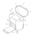
図1は、本実施形態におけるネイルプリント装置の外観を示す斜視図であり、図2は、ネイルプリント装置の内部構成を示す斜視図である。
An embodiment of a nail print apparatus according to the present invention will be described with reference to FIGS.
FIG. 1 is a perspective view illustrating an appearance of a nail print apparatus according to the present embodiment, and FIG. 2 is a perspective view illustrating an internal configuration of the nail print apparatus.
図1に示すように、このネイルプリント装置1は、ケース本体2及び蓋体4を備えている。このケース本体2及び蓋体4は、ケース本体2の上面後端部に設けたヒンジ3を介して、互いに連結されている。
As shown in FIG. 1, the
上記ケース本体2は平面視で長円状に形成されている。このケース本体2には前側には開閉板2cが起倒可能に設けられている。この開閉板2cは、ケース本体2の前面下端部に設けたヒンジ(図示せず)を介して、ケース本体2に連結されている。この開閉板2cは、ケース本体2の前面を開閉するためのものである。
また、ケース本体2の天板2fには後述する操作盤12が設置されており、天板2fのほぼ中央部には表示部13が設定されている。
なお、ケース本体2及び蓋体4の形状、構成はここに例示したものに限定されない。
The
Further, an
Note that the shapes and configurations of the
また、ケース本体2にはネイルプリント装置1の装置本体10が収容されている。この装置本体10は、図2に示す印刷指固定手段を構成している印刷指固定部20、撮影手段を構成している撮影部30、印刷手段を構成している印刷部40及び制御手段を構成している制御装置50(図7参照)を備えている。これら印刷指固定部20、撮影部30、印刷部40及び制御装置50は機枠11に設けられている。
なお、機枠11は下部機枠11a及び上部機枠11bによって構成されている。そして、下部機枠11aは箱状に形成され、ケース本体2の内部下方に設置され、上部機枠11bは下部機枠11aの上方で且つケース本体2の内部上方に設置されている。
Further, the case
The
印刷指固定部20は、機枠11の中の下部機枠11aに設けられている。この下部機枠11aに設けられた印刷指挿入部20a、非印刷指挿入部20b及び掴み部20cによって印刷指固定部20が構成されている。
ここで、印刷指挿入部20aは、印刷しようとする爪Tに対応する指(以下「印刷指」という。)U1を挿入するめための指挿入部である(図3参照)。印刷指挿入部20aの底面(印刷指載置面)は、印刷指U1を載置する指載置手段として機能する。印刷指U1の撮影や印刷は、印刷指U1がこの指載置手段としての印刷指挿入部20aの印刷指載置面に載置された状態で行われる。
また、非印刷指挿入部20bは、印刷指以外の指(以下「非印刷指」という。)U2を挿入するための指挿入部である(図3参照)。
また、掴み部20cは、印刷指挿入部20aに挿入された印刷指U1と、非印刷指挿入部20bに挿入された非印刷指U2とで挟持することが可能な部分である。本実施形態において、この掴み部20cは印刷指挿入部20aと非印刷指挿入部20bとを仕切る隔壁21によって構成されている。
The printing
Here, the printing
Further, the non-printing
The gripping
この隔壁21の上面は平坦な印刷指載置面を構成している。この隔壁21の指挿入側端部には膨出部22が形成されている。この膨出部22は、印刷指挿入部20a及び非印刷指挿入部20bに印刷指U1及び非印刷指U2を深く挿入した際に、印刷指U1及び非印刷指U2の付け根U3が当接する部分に形成されている。膨出部22は、印刷指U1の腹全体が印刷指載置面に当接した状態で、印刷指U1と非印刷指U2とで隔壁21(掴み部20c)を強く挟持することができるように、指挿入方向の断面が、隔壁21の下面から下方に向けて膨出するように円形となっている。なお、膨出部22の形状は、断面円形に限定されることなく、断面楕円形,多角形等の非円形であってもよい。
The upper surface of the
例えば、左手の親指以外の4本の指(人差し指、中指、薬指及び小指)が印刷指U1となる場合には、図3に示すように、ユーザは印刷指挿入部20aに4本の印刷指U1を挿入し、非印刷指挿入部20bに非印刷指U2である親指を挿入する。この場合、ユーザが印刷指挿入部20aに挿入された印刷指U1と、非印刷指挿入部20bに挿入された非印刷指U2とで掴み部20cを挟持することにより、印刷指U1が掴み部20cの上で固定される。
また、親指のみが印刷指U1となる場合には、親指(印刷指U1)を印刷指挿入部20aに挿入さし、親指以外の4本の指(非印刷指U2)を非印刷指挿入部20bに挿入する。この場合にも、ユーザが印刷指U1と非印刷指U2とで掴み部20cを挟持することで印刷指U1が固定される。
For example, when four fingers (index finger, middle finger, ring finger, and little finger) other than the thumb of the left hand are the print fingers U1, the user places four print fingers on the print
When only the thumb becomes the printing finger U1, the thumb (printing finger U1) is inserted into the printing
また、本実施形態では、指載置手段である印刷指載置面を構成している隔壁21の上側の面には、指載置手段上に載置された印刷指U1の輪郭線L1(図10(a)等参照)を印刷指U1の非印刷側から検出する指位置検出手段70が設けられている。
具体的には、指位置検出手段70は、隔壁21の上面の一部であって、印刷指U1が印刷指挿入部20aに挿入された際に印刷指U1の先端部から第一関節辺りまでが位置する部分のほぼ全域に亘って配置されている。
なお、本実施形態のように、人差し指から小指までの4本を同時に印刷指挿入部20aに挿入して印刷を行う装置においては、全ての指の先端部から第一関節辺りに対応する部分全域に指位置検出手段70が設けられる。
また、指位置検出手段70は、印刷指U1の輪郭線を印刷指U1の非印刷側から検出することのできる位置に設けられていればよく、指位置検出手段70が配置される位置は隔壁21の上面に限定されない。
Further, in the present embodiment, the contour line L1 of the printing finger U1 placed on the finger placement means (on the upper surface of the
Specifically, the finger position detecting means 70 is a part of the upper surface of the
Note that, as in the present embodiment, in the apparatus that performs printing by simultaneously inserting four fingers from the index finger to the little finger into the print
Further, the finger position detecting means 70 only needs to be provided at a position where the contour line of the printing finger U1 can be detected from the non-printing side of the printing finger U1, and the position where the finger position detecting means 70 is arranged is a partition wall. The upper surface of 21 is not limited.
指位置検出手段70は、図4に示すように、隔壁21の上面に配置されたカバー部材71と、カバー部材71の下に配置された複数の検出部72とで構成されている。
カバー部材71は、ガラス等の光が透過する材料で形成された板状の部材である。
検出部72は、例えば、光源となる発光素子73とセンサチップ74との対により構成されている。発光素子73としては例えばLED等が用いられる。センサチップ74は、発光素子73から照射されカバー部材71上に載置されている印刷指U1により反射した光を受光する受光素子741と受光素子741によって受光された光を処理する回路部742とから構成されている。なお、検出部72の構成はこれに限定されず、他にレンズ等の光学系を備えていてもよい。
As shown in FIG. 4, the finger
The
The
受光素子741は、例えばCCDやCMOSセンサ等のイメージセンサであり、カバー部材71の表面が印刷指U1で覆われて遮光されたときにこの印刷指U1に反射した光を検出する。回路部742は、受光素子741が検出した光を電気信号に変換する画像処理回路743、画像処理回路743によって変換された電気信号を制御装置50に出力する信号出力回路744(いずれも図7参照)等を備えている。
The
印刷指U1がカバー部材71の表面を覆って遮光すると、印刷指U1で覆われた部分では発光素子73からの光が印刷指U1に反射して受光素子741に入射する。これに対して、印刷指U1で覆われていない部分では光がカバー部材71を透過してしまい、反射しないため受光素子741には光が入射せず光を検出しない。
受光素子741による光の検出、非検出は、画像処理回路743によって電気信号に変換され、受光素子741が光を検出した部分と検出しなかった部分との境界(すなわち、印刷指U1の輪郭線L1(図10(a)等参照))が検出される。検出された印刷指U1の輪郭線L1の情報は、信号出力回路744を介して制御装置50に出力される。
そして、制御装置50は、この輪郭線L1をxy座標値で表したマップとして記憶部51(図7参照)のRAM(図示せず)等に記憶する。この輪郭線L1のxy座標値から印刷指U1の置かれている位置、方向を検出することができる。
なお、検出部72の数や配置は特に限定されないが、印刷指U1の置かれている位置、方向を正確に検出できるように、指位置検出手段70の全面に亘って、隙間なく並べて配置されていることが好ましい。また、検出部72の数が多いほど印刷指U1の輪郭線L1の正確な検出を行うことができ、好ましい。
When the printing finger U1 covers and covers the surface of the
Detection or non-detection of light by the
And the
The number and arrangement of the
また、図5は、本実施形態に係るネイルプリント装置1の正面側の断面図であり、図6は、ネイルプリント装置1の側断面図である。
図5及び図6に示すように、撮影部30は、機枠11の中の上部機枠11bに設けられている。
すなわち、上部機枠11bに設置された基板31の中央部下面には、ドライバーを内蔵した200万画素程度以上の画素を有するカメラ32が設置されている。また、基板31には、カメラ32を囲むように白色LED等の照明灯33が設置されている。撮影部30は、このカメラ32及び照明灯33を備えて構成されている。
この撮影部30は、指載置手段である印刷指挿入部20aに載置された印刷指U1を照明灯33によって照明し、カメラ32によってその印刷指U1を撮影して、指爪画像を得る撮影手段であり、この撮影部30は、後述する制御装置50の本体制御部52に接続され、該本体制御部52によって制御されるようになっている。
5 is a cross-sectional view of the front side of the
As shown in FIGS. 5 and 6, the photographing
That is, a
The photographing
また、印刷部40は、爪領域Taの座標値に基づく印刷用データに従って印刷対象領域である爪領域Ta(図10(a)等参照)に色や模様等の印刷を施す印刷手段であり、主に上部機枠11bに設けられている。
すなわち、図5及び図6に示すように、上部機枠11bの両側板には、2本のガイドロッド41が平行に架設されている。このガイドロッド41には、主キャリッジ42が摺動自在に設置されている。また、図6に示すように、主キャリッジ42の前壁42aおよび後壁42bには2本のガイドロッド44が平行に架設されている。このガイドロッド44には、副キャリッジ45が摺動自在に設置されている。この副キャリッジ45の下面中央部には、印刷ヘッド46が搭載されている。
本実施形態において、この印刷ヘッド46は、インクを微滴化し、被印字媒体に対し直接に吹き付けて印刷を行うインクジェット方式の印刷ヘッドである。なお、印刷ヘッド46の記録方式はインクジェット方式に限定されない。
The
That is, as shown in FIGS. 5 and 6, two
In the present embodiment, the
主キャリッジ42は動力伝達手段(図示せず)を介してモータ43に連結され、モータ43の正逆回転によって、ガイドロッド41に沿って左右方向に移動ように構成されている。また、副キャリッジ45は動力伝達手段(図示せず)を介してモータ47に連結され、モータ47の正逆回転によって、ガイドロッド44に沿って前後方向に移動するように構成されている。
また、下部機枠11aには、印刷ヘッド46にインクを供給するためのインクカートリッジ48が設けられている。インクカートリッジ48は、図示しないインク供給管を介して印刷ヘッド46と接続されており、適宜印刷ヘッド46にインクを供給するようになっている。なお、印刷ヘッド46自体にインクカートリッジを搭載する構成としてもよい。
The
Further, the
印刷部40は、これらガイドロッド41、主キャリッジ42、モータ43、ガイドロッド44、副キャリッジ45、印刷ヘッド46、モータ47及びインクカートリッジ48等を備えて構成されている。この印刷部40のモータ43、印刷ヘッド46、モータ47は、後述する制御装置50の本体制御部52に接続され、該本体制御部52によって制御されるようになっている。
印刷ヘッド46の可動範囲がネイルプリント装置1の印刷可能範囲A(図10(a)等参照)であり、印刷指U1に対する印刷はこの印刷可能範囲内において行われる。
The
The movable range of the
操作盤12は、ユーザが各種入力を行うための入力手段である。
操作盤12には、例えば、ネイルプリント装置1の電源をONする電源スイッチ釦、動作を停止させる停止スイッチ釦、その他各種の入力を行うための操作釦121が配置されている。
The
On the
表示部13は、例えば液晶パネル(液晶ディスプレイ(LCD:Liquid Crystal Display))等で構成された表示手段である。
なお、表示部13の表面に、タッチパネルが一体的に構成されていてもよい。この場合には、図示しないスタイラスペン等によるタッチ操作により、表示部13の表面をタッチすることによっても各種の入力を行うことができるように構成される。
The
A touch panel may be integrally formed on the surface of the
表示部13には、例えば、印刷指U1を撮影した指爪画像やその中の爪領域Ta、印刷指U1の輪郭線L1、印刷指U1の爪領域Taに印刷すべきネイル画像パターン、デザイン確認用のサムネイル画像等が表示されるようになっている。
また、本実施形態では、印刷対象である印刷指U1の爪領域Taが印刷部40の印刷可能範囲内にないと判定されたときには、その旨が表示部13に表示されるようになっており、表示部13は、爪領域Taへの印刷ができないことをユーザに報知する報知手段として機能する。なお、報知される内容は、印刷ができないことのみでなくてもよい。例えば、印刷指U1を右側又は左側等に移動させるように促す等、ユーザに対する具体的な指示を表示させるようにしてもよい。また、印刷可能範囲A内にあるが、指位置がずれて補正が必要な場合に、データを補正中である旨等を表示させてもよい。
The
In the present embodiment, when it is determined that the nail area Ta of the printing finger U1 to be printed is not within the printable range of the
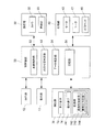
また、制御装置50は、例えば上部機枠11bに配置された基板31等に設置されている。図7は、本実施形態における制御構成を示す要部ブロック図である。
Moreover, the
制御装置50は、図示しないCPU(Central Processing Unit)の他、ROM(Read Only Memory)、RAM(Random Access Memory)等(全て図示せず)で構成される記憶部51を備えるコンピュータである。
The
記憶部51には、印刷すべきネイル画像パターン等のデータや爪領域を決定するための爪領域決定プログラム、印刷可否を判定するための印刷可否判定プログラム、印刷用データを補正するための補正印刷用データ補正プログラム、印刷処理を行うための印刷プログラム等の各種プログラムが格納されており、制御装置50はこれらのプログラムを実行してネイルプリント装置1の各部を制御するようになっている。
本実施形態において記憶部51は、撮影部30によって取得された印刷指U1の指爪画像I1の輪郭線のxy座標値とこの指爪画像I1に含まれる爪領域Taのxy座標値とを対応付けて記憶する第1の記憶部として機能する。
また、指位置検出手段70によって検出された印刷指U1の輪郭線L1のxy座標値を記憶する第2の記憶部として機能する。
The
In the present embodiment, the
Also, it functions as a second storage unit that stores the xy coordinate values of the contour line L1 of the printing finger U1 detected by the finger position detection means 70.
本実施形態において制御装置50は、本体制御部52、印刷可否判定部53、データ補正部54等の機能部を含んでいる。
In the present embodiment, the
本体制御部52は、撮影部30を制御して指爪画像I1を取得させ、撮影部30により取得された指爪画像I1の輪郭線を抽出する。そして、この指爪画像I1の中から爪領域Taを決定して、指爪画像I1の輪郭線のxy座標値とこの指爪画像I1に含まれる爪領域Taのxy座標値とを対応付けて第1の記憶部としての記憶部51のRAM等に記憶させる第1の記憶制御手段として機能する。
また、本体制御部52は、指位置検出手段70によって検出された印刷指U1の輪郭線L1の情報をxy座標値として第2の記憶部としての記憶部51のRAM等に記憶させる第2の記憶制御手段として機能する。
The main
Further, the main
また、本体制御部52は、ユーザの印刷指U1のうち爪領域Taと決定された領域の座標値に基づいて印刷用のデータを生成し、これを印刷部40に出力して、この印刷用データにしたがって爪領域Taに印刷を施すように印刷部40を制御する印刷制御手段として機能する。
Further, the main
印刷可否判定部53は、指爪画像I1の全体の輪郭線xy座標と印刷指U1の輪郭線L1のxy座標を比較対照して、両者に所定値以上のずれがないかを判断し、所定値以上のずれがあれば印刷部40による爪領域Taへの印刷の開始・続行ができないと判定する印刷可否判定手段である。
印刷の開始・続行の可否を決定する際の所定値は、爪領域Taへの印刷に影響を及ぼす程度のずれであるか否かの閾値であり、予めデフォルトで設定されていてもよいし、ユーザが事後的に設定できるようにしてもよい。
The printability determination unit 53 compares and contrasts the entire contour xy coordinates of the fingernail image I1 and the xy coordinates of the contour L1 of the printing finger U1, and determines whether or not there is a deviation greater than a predetermined value. If there is a deviation greater than or equal to the value, it is a print permission / non-permission determination unit that determines that printing on the nail area Ta cannot be started or continued by the
The predetermined value when deciding whether to start or continue printing is a threshold value indicating whether or not the deviation affects the printing on the nail area Ta, and may be set in advance by default, The user may be able to make settings afterwards.
指位置検出手段70は、印刷開始後も随時現時点での印刷指U1の輪郭線L1を検出して制御装置50に出力するようになっており、印刷可否判定部53は、撮影部30によって得られた指爪画像I1に基づく指爪画像I1の全体の輪郭線xy座標と、指位置検出手段70から送られた最新の印刷指U1の輪郭線L1のxy座標を比較対照するようになっている。これにより、印刷開始後、印刷中においても、随時印刷指U1の位置ずれの有無及び位置ずれがある場合にそれが印刷に影響を及ぼすか否かを判定することができる。
The finger position detection means 70 is configured to detect the contour line L1 of the print finger U1 at the present time and output it to the
印刷可否判定部53が爪領域Taへの印刷の開始・続行ができないと判定した場合には、印刷制御手段としての本体制御部52は、印刷部40による爪領域Taへの印刷を停止させるように印刷部40を制御する。
When the printability determination unit 53 determines that printing on the nail area Ta cannot be started or continued, the main
また、印刷可否判定部53は、指爪画像I1の全体の輪郭線xy座標と印刷指U1の輪郭線L1のxy座標を比較対照した結果、両者が印刷に影響を与える程度に(すなわち所定値以上)ずれたと判定した場合に、印刷指U1の輪郭線L1のxy座標値に対応する爪領域Taのxy座標値を推定し、推定された爪領域Taの座標値から、印刷対象である爪領域Taが印刷部40の印刷可能範囲A内にあるか否かを判定する。
印刷可否判定部53が印刷対象である爪領域Taが印刷部40の印刷可能範囲A内にないと判定したときは、印刷制御手段としての本体制御部52は、印刷部40による爪領域Taへの印刷を中止させるように印刷部40を制御し、表示部13にその旨や、印刷指U1の位置の修正をユーザに促す指示等を表示させる。
Further, as a result of comparing and comparing the entire contour line xy coordinates of the fingernail image I1 and the xy coordinates of the contour line L1 of the printing finger U1, the printability determination unit 53 determines that both affect printing (ie, a predetermined value). When it is determined that there is a deviation, the xy coordinate value of the nail area Ta corresponding to the xy coordinate value of the contour line L1 of the printing finger U1 is estimated, and the nail that is the print target is estimated from the estimated coordinate value of the nail area Ta It is determined whether or not the area Ta is within the printable range A of the
When the printability determination unit 53 determines that the nail area Ta to be printed is not within the printable range A of the
データ補正部54は、指爪画像I1の全体の輪郭線xy座標と印刷指U1の輪郭線L1のxy座標を比較対照した結果、両者が印刷に影響を与える程度に(すなわち所定値以上)ずれた場合であって、印刷可否判定部53により印刷対象である爪領域Taが印刷部40の印刷可能範囲内にあると判定されたときに、印刷可否判定部53により推定された爪領域Taのxy座標値に基づいて、印刷用データを補正するデータ補正手段である。
例えば、指位置検出手段70から送られた最新の印刷指U1の輪郭線L1のxy座標が、撮影部30によって得られた指爪画像I1に基づく指爪画像I1の全体の輪郭線xy座標に対して時計回り方向に20度傾いている場合には、指爪画像I1の全体の輪郭線xy座標に対応付けられている爪領域Taのxy座標とのずれ量を補正値として算出し、この補正値によって印刷用データを補正することにより、当初の印刷用データよりも時計回り方向に20度傾いた領域が新たな印刷対象領域となる。
The
For example, the xy coordinate of the latest contour line L1 of the printing finger U1 sent from the finger position detection means 70 becomes the entire contour line xy coordinate of the fingernail image I1 based on the fingernail image I1 obtained by the
データ補正部54により印刷用データが補正されると、印刷制御手段としての本体制御部52は、この補正後の印刷用データに基づいて爪領域Taへの印刷を行うように印刷部40による印刷を制御する。
また、本体制御部52は、データ補正を行うために印刷処理が停止している間、データ補正中である旨等を表示部13に表示させるようにしてもよい。
When the
Further, the main
次に、図8から図12を参照しつつ、本実施形態におけるネイルプリント装置1による印刷制御方法について説明する。
このネイルプリント装置1により印刷を行う場合、ユーザはまず、電源スイッチを入れて制御装置50を起動させ、印刷指U1に印刷したいネイル画像パターン(デザイン)を選択する。選択されたネイル画像パターンは、表示部13に、デザイン確認用のサムネイル画像として表示される。このデザインでよい場合には、ユーザは図示しない確定ボタンでネイル画像パターンを確定させる。
Next, a print control method by the
When printing is performed by the
次に、ユーザは、印刷指U1を印刷指挿入部20aに挿入し、非印刷指U2を非印刷指挿入部20bに挿入して、印刷指U1を固定した上で、印刷スイッチを操作する。
例えば、左手の人差し指、中指、薬指及び小指の爪領域Taに印刷を施したい場合には、図3に示すように、印刷指挿入部20aに人差し指、中指、薬指及び小指を平面的に並べて挿入し、非印刷指挿入部20bに親指を挿入する。そして、印刷指挿入部20aに挿入した人差し指、中指、薬指及び小指と非印刷指挿入部20bに挿入した親指とで掴み部20cを挟持する。これによって、印刷指U1である人差し指、中指、薬指及び小指が固定される。
Next, the user inserts the printing finger U1 into the printing
For example, when printing is to be performed on the index finger, middle finger, ring finger, and nail area Ta of the little finger of the left hand, the index finger, middle finger, ring finger, and little finger are inserted into the print
図8に示すように、制御装置50は、表示部13の印刷スイッチから指示が入力されると、印刷動作を開始する前に、まず撮影部30を制御して、印刷指U1全体を撮影させる。これにより、図10(b)に示すような印刷指U1の指爪画像I1が取得される(ステップS1)。本体制御部52は、この指爪画像I1から印刷対象領域となる爪領域Taを決定する(ステップS2)。そして、印刷指U1全体の輪郭線のxy座標値と、爪領域Taのxy座標値とを対応付けて第1の記憶部としての記憶部51のRAM等に記憶させる(ステップS3)。
また、指位置検出手段70により現時点における印刷指U1の輪郭線L1(図10(a)参照)が検出され(ステップS4)、制御装置50に出力される。制御装置50は、印刷指U1の輪郭線L1のxy座標を第2の記憶部としての記憶部51のRAM等に記憶させる(ステップS5)。
As illustrated in FIG. 8, when an instruction is input from the print switch of the
Further, the finger position detecting means 70 detects the contour line L1 (see FIG. 10A) of the printing finger U1 at the present time (step S4) and outputs it to the
次に、印刷可否判定部53は、印刷対象である印刷指U1の爪領域Taが印刷部40の印刷可能範囲Aの中にあるか否かを判定する(ステップS6)。例えば、図12(a)に示すように、印刷指U1の輪郭線L1が印刷可能範囲Aの外にはみ出している場合には、図12(b)に示すように、この印刷指U1に対応する爪領域Taも印刷可能範囲Aの外にはみ出していると推定される。
印刷可否判定部53により爪領域Taが印刷部40の印刷可能範囲Aの中にないと判定された場合(ステップS6;NO)には、このまま印刷を開始させると印刷すべき絵柄等が爪領域Taからはみ出してしまい、適切に印刷を行うことができない。このため、本体制御部52は、印刷部40による印刷を開始させず、ユーザに対して指位置を修正するように指示する表示を表示部13に表示させる(ステップS7)。そして、印刷指挿入部20aに印刷指U1が載置し直されると、再度ステップS1からステップS6の処理を繰り返す。
Next, the printability determination unit 53 determines whether or not the nail area Ta of the printing finger U1 to be printed is within the printable range A of the printing unit 40 (step S6). For example, as shown in FIG. 12A, when the outline L1 of the printing finger U1 protrudes outside the printable range A, the printing finger U1 corresponds to the printing finger U1 as shown in FIG. It is presumed that the nail area Ta to be protruded outside the printable range A.
When the printability determination unit 53 determines that the nail area Ta is not within the printable range A of the printing unit 40 (step S6; NO), when printing is started as it is, the pattern to be printed becomes the nail area. Since it protrudes from Ta, it cannot print appropriately. Therefore, the main
他方、爪領域Taが印刷部40の印刷可能範囲Aの中にあると判定された場合(ステップS6;YES)には、印刷可否判定部53は、指爪画像I1の輪郭線のxy座標値と現時点での印刷指U1の輪郭線L1のxy座標値とを比較して、両者が印刷に影響を及ぼさない程度に一致しているか否か、すなわち、所定値以上ずれていないか否か(ステップS8)を判定する。そして、両者が完全に一致しているか、ずれたとしても印刷に影響を及ぼさない程度のずれに止まっていると判断した場合(ステップS8;YES)には、本体制御部52は、印刷用データにしたがって爪領域Taへの印刷を開始するように印刷部40を制御する(ステップS9)。
On the other hand, when it is determined that the nail area Ta is within the printable range A of the printing unit 40 (step S6; YES), the printability determination unit 53 determines the xy coordinate value of the contour line of the fingernail image I1. Is compared with the xy coordinate value of the contour line L1 of the printing finger U1 at the present time, and whether or not the two coincide with each other so as not to affect the printing, that is, whether or not the deviation is not less than a predetermined value ( Step S8) is determined. If it is determined that the two are completely coincident or have deviated to such an extent that they do not affect printing even if they deviate (step S8; YES), the main
一方、指爪画像I1の輪郭線のxy座標値と現時点での印刷指U1の輪郭線L1のxy座標値とが所定値以上ずれたと判断した場合(ステップS8;NO)には、本体制御部52は、印刷部40による印刷処理を停止させる(ステップS10)。そして、この場合には、データ補正部54が、両者のずれ量から補正値を算出し、当該補正値により印刷用データを補正する(ステップS11)。そして、本体制御部52は、データ補正部54により補正された補正後の印刷用データにしたがって爪領域Taへの印刷を開始するように印刷部40を制御する(ステップS9)。
On the other hand, when it is determined that the xy coordinate value of the contour line of the fingernail image I1 and the xy coordinate value of the contour line L1 of the printing finger U1 at the present time have shifted by a predetermined value or more (step S8; NO), the main
印刷開始後も指位置検出手段70は随時現時点における印刷指U1の輪郭線L1(例えば、図10(a)、図11(a)、図12(a)参照)を検出し(ステップS12)、制御装置50に検出結果を出力する。
印刷可否判定部53は、指爪画像I1の輪郭線のxy座標値と指位置検出手段70から送られてきた最新の印刷指U1の輪郭線L1のxy座標値とを比較して、両者が印刷に影響を及ぼさない程度に一致しているか否か、すなわち、所定値以上ずれていないか否か(ステップS13)を判定する。そして、両者が完全に一致しているか、ずれたとしても印刷に影響を及ぼさない程度のずれに止まっていると判断した場合(ステップS13;YES)には、本体制御部52は、印刷部40による爪領域Taへの印刷を続行し、随時印刷指U1の爪領域Taへの印刷が完了したかを判断する(ステップS14)。そして、印刷指U1の爪領域Taへの印刷が完了したと判断した場合(ステップS14;YES)には、本体制御部52は、印刷部40による印刷処理を終了する。
他方、爪領域Taへの印刷が完了していないと判断したとき(ステップS14;NO)は、ステップS12に戻って処理を繰り返す。
Even after the printing is started, the finger position detecting means 70 detects the outline L1 of the printing finger U1 at the present time (for example, see FIG. 10A, FIG. 11A, FIG. 12A) (step S12). The detection result is output to the
The printability determination unit 53 compares the xy coordinate value of the contour line of the fingernail image I1 with the xy coordinate value of the latest contour line L1 of the print finger U1 sent from the finger
On the other hand, when it is determined that printing on the nail area Ta has not been completed (step S14; NO), the process returns to step S12 and the process is repeated.
他方、指爪画像I1の輪郭線のxy座標値と最新の印刷指U1の輪郭線L1のxy座標値とが所定値以上ずれたと判断した場合(ステップS13;NO)には、本体制御部52は、印刷部40による印刷処理を停止させる(ステップS15)。そして、印刷可否判定部53は、印刷対象である印刷指U1の爪領域Taが印刷部40の印刷可能範囲Aの中にあるか否かを判定する(ステップS16)。具体的には、最新の印刷指U1の輪郭線L1のxy座標値から、この輪郭線L1に対応する爪領域Taのxy座標値を推定し、推定された爪領域Taのxy座標値から、印刷対象である爪領域Taが印刷部40の印刷可能範囲Aの中にあるか否かを判定する。
On the other hand, when it is determined that the xy coordinate value of the contour line of the fingernail image I1 and the xy coordinate value of the latest contour line L1 of the printing finger U1 have shifted by a predetermined value or more (step S13; NO), the main
例えば、図11(a)に示すように、印刷指U1の輪郭線L1のxy座標値が、撮影部30によって得られた指爪画像I1(図10(b)参照)における印刷指U1全体の輪郭線のxy座標値とずれた場合でも、この印刷指U1の輪郭線L1から推定される爪領域Taの位置は、図11(b)に示すように、印刷可能範囲Aの中に収まっている。これに対して、図12(a)に示すように、印刷指U1の輪郭線L1のxy座標値が印刷可能範囲Aの外にはみ出している場合には、この印刷指U1輪郭線L1のxy座標値に対応するものとして推定される爪領域Taのxy座標値も、図12(b)に示すように、印刷可能範囲Aの外にはみ出していると判定される。なお、図11(b)及び図12(b)では、説明の便宜上、爪領域Taを実線で示している他、印刷指U1全体の輪郭線を二点鎖線で表している。 For example, as shown in FIG. 11A, the xy coordinate value of the contour line L1 of the printing finger U1 is the entire printing finger U1 in the fingernail image I1 obtained by the imaging unit 30 (see FIG. 10B). Even when it deviates from the xy coordinate value of the contour line, the position of the nail region Ta estimated from the contour line L1 of the printing finger U1 is within the printable range A as shown in FIG. Yes. On the other hand, as shown in FIG. 12A, when the xy coordinate value of the contour line L1 of the printing finger U1 protrudes outside the printable range A, the xy of the printing finger U1 contour line L1. It is determined that the xy coordinate value of the nail area Ta estimated to correspond to the coordinate value also protrudes outside the printable range A as shown in FIG. In FIG. 11B and FIG. 12B, for convenience of explanation, the nail region Ta is indicated by a solid line, and the outline of the entire printing finger U1 is indicated by a two-dot chain line.
印刷可否判定部53により爪領域Taが印刷部40の印刷可能範囲Aの中にないと判定された場合(ステップS16;NO、例えば図12(a)・図12(b)参照)には、印刷用データを補正することによっては対処することができないため、本体制御部52は、印刷部40による印刷を中止させる(ステップS17)。なお、この場合、印刷続行ができない旨を表示部13に表示させてもよい。また、印刷指U1を適切な位置に載置し直すようユーザに促す表示を表示部13に表示させてもよい。
When the printability determination unit 53 determines that the nail area Ta is not within the printable range A of the printing unit 40 (step S16; NO, for example, see FIGS. 12A and 12B), Since this cannot be dealt with by correcting the printing data, the main
他方、印刷可否判定部53により、爪領域Taが印刷部40の印刷可能範囲Aの中にあると判定された場合(ステップS16;YES、例えば図11(a)・図11(b)参照)には、データ補正部54が、指爪画像I1の輪郭線のxy座標値と最新の印刷指U1の輪郭線L1のxy座標値とのずれ量に基づき補正値を算出する。そして、この補正値に基づいて、最新の印刷指U1の輪郭線L1のxy座標値に対応するように印刷用データを補正する(ステップS18)。そして、本体制御部52は、データ補正部54により補正された補正後の印刷用データにしたがって爪領域Taへの印刷を再開するように印刷部40を制御する(ステップS19)。
そして、本体制御部52は、随時印刷指U1の爪領域Taへの印刷が完了したかを判断し(ステップS14)、印刷指U1の爪領域Taへの印刷が完了したと判断した場合(ステップS14;YES)には、本体制御部52は、印刷部40による印刷処理を終了する。
他方、爪領域Taへの印刷が完了していないと判断したとき(ステップS14;NO)は、ステップS12に戻って処理を繰り返す。
On the other hand, when the printability determination unit 53 determines that the nail area Ta is within the printable range A of the printing unit 40 (step S16; YES, for example, see FIGS. 11A and 11B). The
Then, the main
On the other hand, when it is determined that printing on the nail area Ta has not been completed (step S14; NO), the process returns to step S12 and the process is repeated.
なお、ここでは、1本の印刷指U1に対する対応について述べたが、本実施形態のように、例えば4本等、複数の印刷指U1に対して同時に印刷処理を行う場合には、以上の処理を各印刷指U1についてそれぞれ繰り返すことにより、全ての印刷指U1について印刷処理を行う。 Here, the correspondence to one printing finger U1 has been described. However, when the printing process is simultaneously performed on a plurality of printing fingers U1, such as four, as in the present embodiment, the above processing is performed. Is repeated for each printing finger U1 to perform printing processing for all printing fingers U1.
以上のように、本実施形態におけるネイルプリント装置1によれば、印刷可否判定部53により、印刷開始前に撮影部30により取得された指爪画像I1の輪郭線のxy座標値と指位置検出手段70から送られてきた最新の印刷指U1の輪郭線L1のxy座標値とを比較して、両者が所定値以上ずれていないか否かを判定し、所定値以上ずれたと判定された場合には、印刷部40による爪領域Taへの印刷を停止させるようになっている。このため、印刷に影響を与える程度に指位置がずれた場合に不適切な位置に誤って印刷されてしまうことを防止することができる。
また、指爪画像I1の輪郭線のxy座標値と最新の印刷指U1の輪郭線L1のxy座標値とが所定値以上ずれた場合には、印刷可否判定部53が、印刷指U1の輪郭線L1のxy座標値に対応する爪領域Taのxy座標値を推定する。そして、推定された爪領域Taが印刷部40の印刷可能範囲Aの中にあるか否かを判定し、印刷対象である爪領域Taが印刷部40の印刷可能範囲A内にないと判定されたときは、印刷部40による印刷を中止させる。このため、印刷部40の印刷可能範囲Aを外れて最早補正によって対応できない場合には不適切な位置に誤って印刷されてしまうことを防止することができる。
また、爪領域Taが印刷部40の印刷可能範囲Aの中にある場合には、データ補正部54が、指爪画像I1の輪郭線のxy座標値と最新の印刷指U1の輪郭線L1のxy座標値とのずれ量に基づいて補正値を算出し、この補正値に基づいて、最新の印刷指U1の輪郭線L1のxy座標値に対応するように印刷用データを補正する。このため、補正で対応可能な場合にはできるだけ補正によって対応することができ、印刷のやり直し等による手間や時間の負担をできる限りユーザにかけないようにすることができる。
また、指位置検出手段70は、印刷指U1の輪郭線L1を印刷指U1の非印刷側から検出することができるため、印刷が開始された後も随時印刷指U1の位置(輪郭線L1のxy座標値)を検出することができ、印刷開始後に印刷指U1が動いてしまった場合にも印刷の停止・中止、印刷用データの補正等の対応を適切に行うことができる。
また、印刷対象である爪領域Taが印刷部40の印刷可能範囲A内にないと判定されたときには、その旨を表示部13に表示させる等により報知するため、ユーザは、印刷指U1の載置し直し等の対応をすることができる。
As described above, according to the
Further, when the xy coordinate value of the contour line of the fingernail image I1 and the xy coordinate value of the latest contour line L1 of the printing finger U1 are shifted by a predetermined value or more, the printability determination unit 53 determines the contour of the printing finger U1. The xy coordinate value of the nail region Ta corresponding to the xy coordinate value of the line L1 is estimated. Then, it is determined whether or not the estimated nail area Ta is within the printable range A of the
When the nail area Ta is in the printable range A of the
In addition, since the finger
Further, when it is determined that the nail area Ta to be printed is not within the printable range A of the
なお、本実施形態では、指位置検出手段70として、発光素子73と受光素子741とを備える検出部72を複数備えているものを例示したが、指位置検出手段70の構成はここに示したものに限定されない。指位置検出手段70は、印刷指載置面に載置された印刷指U1の位置や向きを検出することのできるものであればここに例示した以外の構成のものでも適用可能であり、例えば、指紋センサや静脈センサ等を用いてもよい。
指位置検出手段70として指紋センサや静脈センサ等を用いる場合には、指位置検出手段70を用いて、印刷を行うユーザを識別し、当該ユーザが過去に選択した絵柄を印刷する絵柄としてデフォルト設定したり、当該ユーザについて過去に撮影された指爪画像をユーザの印刷指U1の情報として用いる等、個別のユーザに対応した処理を行うように構成してもよい。
In the present embodiment, the finger
When a fingerprint sensor, a vein sensor, or the like is used as the finger
また、本実施形態では、表示部13を報知手段として機能させ、表示部13に爪領域Taが印刷部40の印刷可能範囲A内にない旨の表示や、印刷指U1の載置し直しを促す表示等をさせるようにしたが、報知手段は表示部13に限定されない。例えばブザーや音声案内等を発するスピーカ等の音声発生手段を備え、これを報知手段として用いてもよい。
また、報知手段は、爪領域Taが印刷部40の印刷可能範囲A内にない旨等をランプの点灯、点滅等によりユーザに報知するものでもよい。
Further, in the present embodiment, the
Further, the notifying means may notify the user that the nail area Ta is not within the printable range A of the
また、本実施形態では、水平方向における印刷指U1の位置ずれを主として説明したが、例えば印刷指U1が印刷開始前に設定した当初の位置よりも上に上がってしまった場合等、指載置手段からの印刷指U1の離れ、浮き上がり等についても指位置検出手段70によって検出して、印刷指U1の離れ、浮き上がり等がある場合には印刷を開始しない、または印刷途中である場合には印刷を停止させるようにしてもよい。この場合、これが補正可能な範囲内か否かを判断し、補正可能な範囲であれば、補正によって対応した後に印刷を再開する。また、補正不能である場合には、印刷を中止してその旨を表示部13によりユーザに報知するようにする。
Further, in the present embodiment, the positional deviation of the printing finger U1 in the horizontal direction has been mainly described. However, for example, when the printing finger U1 is raised above the initial position set before starting printing, the finger placement is performed. The finger position detecting means 70 also detects the separation and lifting of the printing finger U1 from the means, and if the printing finger U1 is separated or lifted, the printing is not started or printing is in progress. May be stopped. In this case, it is determined whether or not this is within the correctable range, and if it is within the correctable range, printing is resumed after the correction is made. If correction is not possible, printing is stopped and the
また、本実施形態では、第1の記憶部、第2の記憶部が制御装置50の記憶部51である場合を例としたが、第1の記憶部、第2の記憶部は制御装置50の記憶部51に限定されず、別途記憶部が設けられていてもよい。
In the present embodiment, the first storage unit and the second storage unit are the
また、本実施形態では、4本の指に対して同時に印刷を行うことのできるネイルプリント装置1を例としたが、指を1本ずつ装置に挿入して順次印刷を行う装置に本発明を適用することも可能である。
In the present embodiment, the
その他、本発明が本実施形態に限定されず、適宜変更可能であることはいうまでもない。 In addition, it cannot be overemphasized that this invention is not limited to this embodiment, and can be changed suitably.
1 ネイルプリント装置
2 ケース本体
4 蓋体
20a 印刷指挿入部
21 隔壁
30 撮影部
40 印刷部
50 制御装置
51 記憶部
52 本体制御部
53 印刷可否判定部
54 データ補正部
I1 指爪画像
L1 輪郭線
T 爪
Ta 爪領域
U1 印刷指
U2 非印刷指
DESCRIPTION OF
Claims (9)
この指載置手段上に載置された指を撮影して指爪画像を得る撮影手段と、
この撮影手段によって取得された前記指爪画像の輪郭線の座標値とこの指爪画像に含まれる爪領域の座標値とを対応付けて記憶する第1の記憶部と、
前記爪領域に印刷を施す印刷手段と、
前記第1の記憶部に前記指爪画像の前記輪郭線の座標値と前記指爪画像に含まれる前記爪領域の座標値とを対応付けて記憶したあとに、前記指載置手段上に載置された指の輪郭線を指の非印刷側から検出する指位置検出手段と、
前記指位置検出手段によって検出された指の輪郭線の座標値を記憶する第2の記憶部と、
前記印刷手段による前記爪領域への印刷を制御する制御手段と、を備えており、
前記制御手段は、
前記第1の記憶部に記憶されている前記指爪画像の輪郭線の座標値と前記第2の記憶部に記憶されている指の輪郭線の座標値とを比較して、両者が所定値以上ずれたか否かを判定する印刷可否判定手段を含み、
前記制御手段は、前記印刷可否判定手段により両者が所定値以上ずれたと判定された場合に、前記印刷手段による前記爪領域への印刷を停止させることを特徴とするネイルプリント装置。 Finger placement means on which a finger is placed;
Photographing means for photographing a finger placed on the finger placing means to obtain a fingernail image;
A first storage unit that stores the coordinate value of the contour line of the fingernail image acquired by the photographing unit and the coordinate value of the nail region included in the fingernail image in association with each other;
Printing means for printing on the nail region;
After storing the coordinate value of the contour line of the fingernail image and the coordinate value of the nail region included in the fingernail image in the first storage unit in association with each other, the coordinate value is placed on the finger placement unit. Finger position detecting means for detecting the contour line of the placed finger from the non-printing side of the finger;
A second storage unit for storing the coordinate value of the contour line of the finger detected by the finger position detection unit;
Control means for controlling printing on the nail region by the printing means,
The control means includes
The coordinate value of the contour line of the fingernail image stored in the first storage unit and the coordinate value of the contour line of the finger stored in the second storage unit are compared, and both are predetermined values. Including a printability determination unit that determines whether or not the deviation has occurred;
The nail printing apparatus according to claim 1, wherein the control unit stops printing on the nail region by the printing unit when it is determined by the printing propriety determining unit that both are shifted by a predetermined value or more.
前記第1の記憶部に記憶されている前記指爪画像の輪郭線の座標値と前記第2の記憶部に記憶されている指の輪郭線の座標値とが所定値以上ずれた場合に、前記第2の記憶部に記憶されている指の輪郭線の座標値に対応する爪領域の座標値を推定し、推定された爪領域の座標値から、印刷対象である爪領域が前記印刷手段の印刷可能範囲内にあるか否かを判定し、
前記制御手段は、前記印刷可否判定手段により印刷対象である爪領域が前記印刷手段の印刷可能範囲内にないと判定されたときは、前記印刷手段による印刷を中止させることを特徴とする請求項1に記載のネイルプリント装置。 The print availability determination unit includes:
When the coordinate value of the contour line of the fingernail image stored in the first storage unit and the coordinate value of the contour line of the finger stored in the second storage unit are shifted by a predetermined value or more, The coordinate value of the nail region corresponding to the coordinate value of the finger outline stored in the second storage unit is estimated, and the nail region to be printed is determined from the estimated coordinate value of the nail region by the printing unit. To determine whether it is within the printable range of
The said control means stops printing by the said printing means, when it determines with the nail | claw area | region which is a printing object not being in the printable range of the said printing means by the said printing availability determination means. The nail printing apparatus according to 1.
前記第1の記憶部に記憶されている前記指爪画像の輪郭線の座標値と前記第2の記憶部に記憶されている指の輪郭線の座標値とが所定値以上ずれた場合であって、前記印刷可否判定手段により印刷対象である爪領域が前記印刷手段の印刷可能範囲内にあると判定されたときに、前記印刷可否判定手段により推定された爪領域の座標値に基づいて、前記爪領域の座標値に基づく印刷用データを補正するデータ補正手段を含み、
前記制御手段は、前記データ補正手段により補正された後の印刷用データに基づいて印刷を行うように前記印刷手段を制御することを特徴とする請求項1又は請求項2に記載のネイルプリント装置。 The control means includes
This is a case where the coordinate value of the contour line of the fingernail image stored in the first storage unit and the coordinate value of the contour line of the finger stored in the second storage unit are shifted by a predetermined value or more. When the nail area to be printed is determined to be within the printable range of the printing means by the printing availability determining means, based on the coordinate value of the nail area estimated by the printing availability determining means, Including data correction means for correcting printing data based on the coordinate values of the nail region;
3. The nail printing apparatus according to claim 1, wherein the control unit controls the printing unit to perform printing based on the printing data corrected by the data correction unit. .
前記撮影ステップにおいて取得された前記指爪画像の輪郭線の座標値とこの指爪画像に含まれる爪領域の座標値とを対応付けて記憶する第1の記憶ステップと、
印刷手段により前記爪領域に印刷を施す印刷ステップと、
前記第1の記憶部に前記指爪画像の前記輪郭線の座標値と前記指爪画像に含まれる前記爪領域の座標値とを対応付けて記憶したあとに、前記指載置手段上に載置された指の輪郭線を指の非印刷側から検出する指位置検出ステップと、
前記指位置検出ステップにおいて検出された指の輪郭線の座標値を記憶する第2の記憶ステップと、
前記第1の記憶ステップにおいて記憶された前記指爪画像の輪郭線の座標値と前記第2の記憶ステップにおいて記憶された指の輪郭線の座標値とを比較して、両者が所定値以上ずれた場合には印刷の開始・続行ができないと判定する印刷可否判定ステップと、
前記印刷可否判定ステップにおいて印刷の開始・続行ができないと判定された場合に、前記印刷手段による前記爪領域への印刷を停止させる印刷制御ステップと、
を含んでいることを特徴とする印刷制御方法。 A photographing step of photographing a finger placed on the finger placing means to obtain a fingernail image;
A first storage step for storing the coordinate value of the contour line of the fingernail image acquired in the photographing step in association with the coordinate value of the nail region included in the fingernail image;
A printing step of printing on the nail region by a printing means;
After storing the coordinate value of the contour line of the fingernail image and the coordinate value of the nail region included in the fingernail image in the first storage unit in association with each other, the coordinate value is placed on the finger placement unit. A finger position detecting step for detecting the contour line of the placed finger from the non-printing side of the finger;
A second storage step of storing the coordinate value of the contour line of the finger detected in the finger position detection step;
The coordinate value of the contour line of the fingernail image stored in the first storage step is compared with the coordinate value of the contour line of the finger stored in the second storage step. A printability determination step that determines that printing cannot be started or continued if
A printing control step of stopping printing on the nail region by the printing means when it is determined that printing cannot be started / continued in the printing propriety determination step;
A printing control method comprising:
前記第1の記憶ステップにおいて記憶された前記指爪画像の輪郭線の座標値と前記第2の記憶ステップにおいて記憶された指の輪郭線の座標値とが所定値以上ずれた場合に、前記第2の記憶ステップにおいて記憶された指の輪郭線の座標値に対応する爪領域の座標値を推定し、推定された爪領域の座標値から、印刷対象である爪領域が前記印刷手段の印刷可能範囲内にあるか否かを判定するステップを含み、
前記印刷制御ステップは、前記印刷可否判定ステップにおいて印刷対象である爪領域が前記印刷手段の印刷可能範囲内にないと判定されたときは、前記印刷手段による印刷を中止させることを特徴とする請求項5に記載の印刷制御方法。 The printing propriety determination step includes
When the coordinate value of the contour line of the fingernail image stored in the first storage step and the coordinate value of the finger contour line stored in the second storage step deviate by a predetermined value or more, the first The coordinate value of the nail region corresponding to the coordinate value of the contour line of the finger stored in step 2 is estimated, and the nail region to be printed can be printed by the printing unit from the estimated coordinate value of the nail region. Determining whether it is within range,
The printing control step stops printing by the printing unit when it is determined that the nail area to be printed is not within the printable range of the printing unit in the printing propriety determination step. Item 6. The print control method according to Item 5.
前記第1の記憶ステップにおいて記憶された前記指爪画像の輪郭線の座標値と前記第2の記憶ステップにおいて記憶された指の輪郭線の座標値とが所定値以上ずれた場合であって、前記印刷可否判定ステップにおいて印刷対象である爪領域が前記印刷手段の印刷可能範囲内にあると判定されたときに、前記印刷可否判定ステップおいて推定された爪領域の座標値に基づいて、前記爪領域の座標値に基づく印刷用データを補正するデータ補正ステップを含み、
前記印刷制御ステップは、前記データ補正ステップにおいて補正された後の印刷用データに基づいて印刷を行うように前記印刷手段を制御することを特徴とする請求項5又は請求項6に記載の印刷制御方法。 The printing control step includes
The coordinate value of the contour line of the fingernail image stored in the first storage step and the coordinate value of the contour line of the finger stored in the second storage step are shifted by a predetermined value or more, When it is determined in the printability determination step that the nail region to be printed is within the printable range of the printing unit, based on the coordinate value of the nail region estimated in the printability determination step, Including a data correction step of correcting data for printing based on the coordinate value of the nail region,
7. The print control according to claim 5, wherein the print control step controls the printing unit to perform printing based on the print data corrected in the data correction step. Method.
この指載置手段上に載置された指を撮影して指爪画像を得る撮影手段と、
この撮影手段によって取得された前記指爪画像の輪郭線の座標値とこの指爪画像に含まれる爪領域の座標値とを対応付けて記憶させる第1の記憶制御手段と、
この第1の記憶制御手段の制御により前記指爪画像の輪郭線の座標値と前記爪領域の座標値とを対応付けて記憶させたあとに、前記指載置手段上に載置された指の位置を検出する指位置検出手段と、
前記指位置検出手段によって検出された指の輪郭線の座標値を記憶させる第2の記憶制御手段と、
この第2の記憶制御手段の制御により記憶されている前記指の輪郭線の座標値と前記第1の記憶制御手段の制御により記憶されている前記指爪画像の輪郭線の座標値とを比較して、両者が所定値以上ずれたか否かを判定する印刷可否判定手段と、
この印刷可否判定手段により両者が所定値以上ずれたと判定された場合には、前記指載置手段上に載置された指の爪領域への印刷を停止し、両者が所定値以上ずれていないと判定された場合には、前記指載置手段上に載置された指の爪領域への印刷を施すように制御する印刷制御手段と、
を備えていることを特徴とするネイルプリント装置。 Finger placement means on which a finger is placed;
Photographing means for photographing a finger placed on the finger placing means to obtain a fingernail image;
First storage control means for storing the coordinate value of the contour line of the fingernail image acquired by the photographing means and the coordinate value of the nail region included in the fingernail image in association with each other;
After the coordinate values of the contour line of the fingernail image and the coordinate values of the nail region are stored in association with each other by the control of the first storage control unit, the finger placed on the finger placement unit is stored. Finger position detecting means for detecting the position of
Second storage control means for storing coordinate values of the contour line of the finger detected by the finger position detection means;
The coordinate value of the second storage control means contour of the fingernail image being more stored in the control of the first storage control means and the coordinate values of the contour line of the finger stored by the control of the In comparison, a printability determination unit that determines whether or not both have deviated by a predetermined value or more;
If it is determined by the printability determination unit that both have deviated by a predetermined value or more, printing on the fingernail area placed on the finger placing unit is stopped, and both have not deviated by a predetermined value or more. A print control means for controlling to perform printing on the fingernail area placed on the finger placement means,
A nail printing apparatus comprising:
前記撮影手段によって取得された前記指爪画像の輪郭線の座標値とこの指爪画像に含まれる爪領域の座標値とを対応付けて記憶させる第1の記憶制御ステップと、
この第1の記憶制御ステップの制御により前記指爪画像の輪郭線の座標値と前記爪領域の座標値とを対応付けて記憶させたあとに、前記指載置手段上に載置された指の位置を検出する指位置検出ステップと、
前記指位置検出ステップによって検出された指の輪郭線の座標値を記憶させる第2の記憶制御ステップと、
この第2の記憶制御ステップの制御により記憶されている前記指の輪郭線の座標値と前記第1の記憶制御ステップの制御により記憶されている前記指爪画像の輪郭線の座標値とを比較して、両者が所定値以上ずれたか否かを判定する印刷可否判定ステップと、
この印刷可否判定ステップにより両者が所定値以上ずれたと判定された場合には、前記指載置手段上に載置された指の爪領域への印刷を停止し、両者が所定値以上ずれていないと判定された場合には、前記指載置手段上に載置された指の爪領域への印刷を施すように制御する印刷制御ステップと、
を備えていることを特徴とする印刷制御方法。 In a printing control method used in a nail printing apparatus including a finger placing unit on which a finger is placed and a photographing unit that takes a finger placed on the finger placing unit and obtains a fingernail image ,
A first storage control step of storing the coordinate value of the contour line of the fingernail image acquired by the photographing unit and the coordinate value of the nail region included in the fingernail image in association with each other;
The finger placed on the finger placement means after the coordinate value of the contour line of the fingernail image and the coordinate value of the nail region are stored in association with each other by the control of the first storage control step. A finger position detecting step for detecting the position of
A second storage control step of storing the coordinate value of the contour line of the finger detected by the finger position detection step;
The coordinate values of the contour line of the second storage control step the fingernail image being more stored in the control of the coordinate values of the contour line of the finger stored the first storage control step by the control of the In comparison, a printability determination step for determining whether or not both have deviated by a predetermined value or more;
If it is determined in this printability determination step that both have deviated by a predetermined value or more, printing on the fingernail area placed on the finger placing means is stopped, and both have not deviated by a predetermined value or more. A print control step for controlling to perform printing on the fingernail area placed on the finger placement means,
A printing control method comprising:
Priority Applications (1)
| Application Number | Priority Date | Filing Date | Title |
|---|---|---|---|
| JP2010237106A JP5728885B2 (en) | 2010-10-22 | 2010-10-22 | Nail printing apparatus and printing control method |
Applications Claiming Priority (1)
| Application Number | Priority Date | Filing Date | Title |
|---|---|---|---|
| JP2010237106A JP5728885B2 (en) | 2010-10-22 | 2010-10-22 | Nail printing apparatus and printing control method |
Related Child Applications (1)
| Application Number | Title | Priority Date | Filing Date |
|---|---|---|---|
| JP2015078829A Division JP5991401B2 (en) | 2015-04-08 | 2015-04-08 | Nail printing apparatus and printing control method |
Publications (3)
| Publication Number | Publication Date |
|---|---|
| JP2012085944A JP2012085944A (en) | 2012-05-10 |
| JP2012085944A5 JP2012085944A5 (en) | 2013-11-14 |
| JP5728885B2 true JP5728885B2 (en) | 2015-06-03 |
Family
ID=46258226
Family Applications (1)
| Application Number | Title | Priority Date | Filing Date |
|---|---|---|---|
| JP2010237106A Active JP5728885B2 (en) | 2010-10-22 | 2010-10-22 | Nail printing apparatus and printing control method |
Country Status (1)
| Country | Link |
|---|---|
| JP (1) | JP5728885B2 (en) |
Families Citing this family (11)
| Publication number | Priority date | Publication date | Assignee | Title |
|---|---|---|---|---|
| JP5831441B2 (en) * | 2012-12-17 | 2015-12-09 | カシオ計算機株式会社 | Nail printing apparatus and printing method for nail printing apparatus |
| US11265444B2 (en) * | 2013-08-23 | 2022-03-01 | Preemadonna Inc. | Apparatus for applying coating to nails |
| US9687059B2 (en) * | 2013-08-23 | 2017-06-27 | Preemadonna Inc. | Nail decorating apparatus |
| JP6384150B2 (en) * | 2014-07-01 | 2018-09-05 | カシオ計算機株式会社 | Drawing apparatus and drawing control method of drawing apparatus |
| GB2563766B (en) * | 2014-07-23 | 2019-03-27 | Preemadonna Inc | Apparatus for applying coating to nails |
| JP7079810B2 (en) * | 2014-07-23 | 2022-06-02 | プリマドンナ,インコーポレイテッド | A device for applying a coating to the nails |
| JP6596979B2 (en) * | 2015-06-30 | 2019-10-30 | カシオ計算機株式会社 | Drawing apparatus and drawing method of drawing apparatus |
| JP6493198B2 (en) | 2015-12-22 | 2019-04-03 | カシオ計算機株式会社 | Drawing apparatus and drawing method of drawing apparatus |
| WO2019070886A1 (en) | 2017-10-04 | 2019-04-11 | Preemadonna Inc. | Systems and methods of adaptive nail printing and collaborative beauty platform hosting |
| EP3773063A1 (en) * | 2018-04-13 | 2021-02-17 | Coral Labs, Inc. | System and method for accurate application and curing of nail polish |
| JP6973437B2 (en) * | 2019-03-25 | 2021-11-24 | カシオ計算機株式会社 | Printing equipment, printing methods and programs |
Family Cites Families (5)
| Publication number | Priority date | Publication date | Assignee | Title |
|---|---|---|---|---|
| AU1353299A (en) * | 1997-12-24 | 1999-07-19 | Jit Ceremony Co., Ltd. | Nail art method and device |
| JP2000006384A (en) * | 1998-06-25 | 2000-01-11 | Mitsumi Electric Co Ltd | Printing device capable of printing on three-dimensional surface |
| US6286517B1 (en) * | 1998-12-22 | 2001-09-11 | Pearl Technology Holdings, Llc | Fingernail and toenail decoration using ink jets |
| JP3016147B1 (en) * | 1998-12-25 | 2000-03-06 | 株式会社アトラス | Nail art equipment |
| JP2006255196A (en) * | 2005-03-17 | 2006-09-28 | Seiko Epson Corp | Nail drawing device and nail drawing method |
-
2010
- 2010-10-22 JP JP2010237106A patent/JP5728885B2/en active Active
Also Published As
| Publication number | Publication date |
|---|---|
| JP2012085944A (en) | 2012-05-10 |
Similar Documents
| Publication | Publication Date | Title |
|---|---|---|
| JP5728885B2 (en) | Nail printing apparatus and printing control method | |
| JP5141742B2 (en) | Nail printing apparatus and printing control method | |
| CN109123989B (en) | Drawing system, terminal device, and recording medium | |
| JP6268771B2 (en) | Nail printing apparatus, printing method and program for nail printing apparatus | |
| JP6439342B2 (en) | Nail information detection device, drawing device, and nail information detection method | |
| US8919903B2 (en) | Nail printing device including printing head that performs printing on fingernail, and printing control method | |
| US10696067B2 (en) | Nail printing apparatus and control method | |
| US8919898B2 (en) | Nail print apparatus including display control unit distinguishing between fingernail under printing and fingernail not under printing to display fingernail | |
| JP5991401B2 (en) | Nail printing apparatus and printing control method | |
| JP5601103B2 (en) | Nail printing apparatus and printing control method | |
| US20130077103A1 (en) | Color correction print apparatus and print control method | |
| CN111728344B (en) | Printing apparatus and printing method | |
| JP2008186120A (en) | Processor, processing method and program for executing processing according to user's instruction | |
| JP5435108B2 (en) | Nail printing apparatus and printing control method | |
| JP2013039169A (en) | Nail printer and method for controlling print | |
| JP2013192680A (en) | Nail printing device and print control method | |
| JP5928264B2 (en) | Nail printing apparatus and printing control method | |
| US20220379638A1 (en) | Printing device, printing method, and storage medium | |
| JP2013039170A (en) | Nail printer, and method for controlling print | |
| JP7067166B2 (en) | Nail printing device, finger type determination method and program | |
| JP7294469B2 (en) | NAIL PRINTING DEVICE, CONTROL METHOD AND PROGRAM FOR NAIL PRINTING DEVICE | |
| JP7173256B2 (en) | Drawing system and drawing control method | |
| JP2023038725A (en) | Electronic apparatus, determination method and program | |
| BR102013022795B1 (en) | NAIL PRINT APPLIANCE AND PRINT CONTROL METHOD |
Legal Events
| Date | Code | Title | Description |
|---|---|---|---|
| A521 | Written amendment |
Free format text: JAPANESE INTERMEDIATE CODE: A523 Effective date: 20130925 |
|
| A621 | Written request for application examination |
Free format text: JAPANESE INTERMEDIATE CODE: A621 Effective date: 20130925 |
|
| A131 | Notification of reasons for refusal |
Free format text: JAPANESE INTERMEDIATE CODE: A131 Effective date: 20140708 |
|
| A977 | Report on retrieval |
Free format text: JAPANESE INTERMEDIATE CODE: A971007 Effective date: 20140710 |
|
| A521 | Written amendment |
Free format text: JAPANESE INTERMEDIATE CODE: A523 Effective date: 20140905 |
|
| TRDD | Decision of grant or rejection written | ||
| A01 | Written decision to grant a patent or to grant a registration (utility model) |
Free format text: JAPANESE INTERMEDIATE CODE: A01 Effective date: 20150310 |
|
| A61 | First payment of annual fees (during grant procedure) |
Free format text: JAPANESE INTERMEDIATE CODE: A61 Effective date: 20150323 |
|
| R150 | Certificate of patent or registration of utility model |
Ref document number: 5728885 Country of ref document: JP Free format text: JAPANESE INTERMEDIATE CODE: R150 |