JP2013051402A - Choke coil and manufacturing method of the same - Google Patents
Choke coil and manufacturing method of the same Download PDFInfo
- Publication number
- JP2013051402A JP2013051402A JP2012152352A JP2012152352A JP2013051402A JP 2013051402 A JP2013051402 A JP 2013051402A JP 2012152352 A JP2012152352 A JP 2012152352A JP 2012152352 A JP2012152352 A JP 2012152352A JP 2013051402 A JP2013051402 A JP 2013051402A
- Authority
- JP
- Japan
- Prior art keywords
- core
- bobbin
- coil
- choke coil
- outer core
- Prior art date
- Legal status (The legal status is an assumption and is not a legal conclusion. Google has not performed a legal analysis and makes no representation as to the accuracy of the status listed.)
- Pending
Links
Images


Classifications
-
- H—ELECTRICITY
- H01—ELECTRIC ELEMENTS
- H01F—MAGNETS; INDUCTANCES; TRANSFORMERS; SELECTION OF MATERIALS FOR THEIR MAGNETIC PROPERTIES
- H01F3/00—Cores, Yokes, or armatures
- H01F3/08—Cores, Yokes, or armatures made from powder
-
- H—ELECTRICITY
- H01—ELECTRIC ELEMENTS
- H01F—MAGNETS; INDUCTANCES; TRANSFORMERS; SELECTION OF MATERIALS FOR THEIR MAGNETIC PROPERTIES
- H01F27/00—Details of transformers or inductances, in general
- H01F27/24—Magnetic cores
- H01F27/255—Magnetic cores made from particles
-
- H—ELECTRICITY
- H01—ELECTRIC ELEMENTS
- H01F—MAGNETS; INDUCTANCES; TRANSFORMERS; SELECTION OF MATERIALS FOR THEIR MAGNETIC PROPERTIES
- H01F27/00—Details of transformers or inductances, in general
- H01F27/24—Magnetic cores
- H01F27/26—Fastening parts of the core together; Fastening or mounting the core on casing or support
-
- H—ELECTRICITY
- H01—ELECTRIC ELEMENTS
- H01F—MAGNETS; INDUCTANCES; TRANSFORMERS; SELECTION OF MATERIALS FOR THEIR MAGNETIC PROPERTIES
- H01F27/00—Details of transformers or inductances, in general
- H01F27/28—Coils; Windings; Conductive connections
- H01F27/32—Insulating of coils, windings, or parts thereof
- H01F27/324—Insulation between coil and core, between different winding sections, around the coil; Other insulation structures
- H01F27/325—Coil bobbins
-
- H—ELECTRICITY
- H01—ELECTRIC ELEMENTS
- H01F—MAGNETS; INDUCTANCES; TRANSFORMERS; SELECTION OF MATERIALS FOR THEIR MAGNETIC PROPERTIES
- H01F37/00—Fixed inductances not covered by group H01F17/00
-
- H—ELECTRICITY
- H01—ELECTRIC ELEMENTS
- H01F—MAGNETS; INDUCTANCES; TRANSFORMERS; SELECTION OF MATERIALS FOR THEIR MAGNETIC PROPERTIES
- H01F27/00—Details of transformers or inductances, in general
- H01F27/28—Coils; Windings; Conductive connections
- H01F27/30—Fastening or clamping coils, windings, or parts thereof together; Fastening or mounting coils or windings on core, casing, or other support
- H01F27/306—Fastening or mounting coils or windings on core, casing or other support
Landscapes
- Engineering & Computer Science (AREA)
- Power Engineering (AREA)
- Coils Or Transformers For Communication (AREA)
- Insulating Of Coils (AREA)
Abstract
Description
本発明は、主として電源回路の昇圧用、力率改善用又は電流平滑用として用いられるチョークコイルに関する。 The present invention relates to a choke coil used mainly for boosting a power supply circuit, improving a power factor, or current smoothing.
チョークコイルは、例えば、電源回路の昇圧用、力率改善用又は電流平滑用として用いられている。従来のチョークコイルは、一対のコアと、コイルを巻回したボビンとを、互いに抱き合わせた構成となっている。例えば、フェライトコア用のコア形状として、ERコアが知られている(例えば、特許文献1参照。)。図20は、ERコア型のチョークコイル100の構成例を示す分解斜視図である。図において、このチョークコイル100は、上下一対のコア101と、コイル103が巻回された円筒状のボビン102とを備えている。
The choke coil is used, for example, for boosting a power supply circuit, for power factor improvement, or for current smoothing. A conventional choke coil has a configuration in which a pair of cores and a bobbin around which a coil is wound are entangled with each other. For example, an ER core is known as a core shape for a ferrite core (see, for example, Patent Document 1). FIG. 20 is an exploded perspective view showing a configuration example of the ER core
コア101は、ボビン102の軸方向両端に設けられている環状鍔部102aの外周形状と、ボビン102の中心に形成されている孔102bの形状とに合わせた凹凸形状となるように、両端の凸部101aと中央の円柱部101bとを有している。孔102bに上下一対のコア101の円柱部101bを入れ、かつ、外側の凸部101a同士を当接させた状態で全体を固定すれば、チョークコイル100が出来上がる。なお、例えば、外側の凸部101a同士を当接させた状態で、円柱部101b同士は当接せず、一定のギャップを形成するように構成されている。ギャップの存在により、磁気飽和が抑制される。
The
また、ERコアとは異なるEEコアも、よく知られている(例えば、特許文献2参照。)。図21は、EEコア型のチョークコイル200の構成例を示す斜視図である。図において、このチョークコイル200は、上下一対のコア201と、コイル203が巻回された角形のボビン202とを備えている。
An EE core different from the ER core is also well known (see, for example, Patent Document 2). FIG. 21 is a perspective view showing a configuration example of an EE core
コア201は、ボビン202の軸方向両端に設けられている方形鍔部202aの外形状と、ボビン202の中心に形成された孔202bの形状とに合わせた凹凸形状となるように、両端の凸部201aと中央の凸部201bとを有している。孔202bに上下一対のコア201の中央の凸部201bを入れ、かつ、外側の凸部201a同士を当接させた状態で全体を固定すれば、チョークコイル200が出来上がる。なお、例えば、外側の凸部201a同士を当接させた状態で、中央の凸部201b同士は当接せず、一定のギャップを形成するように構成されている。
The
ここで、コアの材質としては、一般に、珪素鋼板、フェライト、アモルファスリボンが使用されてきたが、これらに代えて、ダストコア(圧粉磁心)を用いるチョークコイルを作製したい。ダストコアは、高周波域での損失が少なく、比較的、飽和磁束密度が高い、という利点がある。
ところが、ダストコアによってERコアを作製しようとすると、コアの形状が複雑なため、1ストロークでプレス成形することはできず、NCプレス機を用いて数値制御された高度なプレス工程を必要とする。従って、成形コストが高くなる。また、形状が複雑であるため、局部的に応力集中し易い部位が多くある。そのため、コアが割れ易く、機械的強度が不足する。
Here, silicon steel plates, ferrites, and amorphous ribbons have generally been used as the core material, but instead of these, a choke coil using a dust core (a dust core) is desired. The dust core has the advantages of low loss in the high frequency region and relatively high saturation magnetic flux density.
However, when an ER core is produced using a dust core, the shape of the core is complicated, so that it cannot be press-molded in one stroke, and requires an advanced press process that is numerically controlled using an NC press. Therefore, the molding cost is increased. In addition, since the shape is complicated, there are many sites where stress is likely to be concentrated locally. Therefore, the core is easily broken and the mechanical strength is insufficient.
一方、ダストコアによってEEコアを作製しようとすると、Eの字に見える方向からコアを見たときの横断面形状は、どこで切ってもE字状であるから、プレス成形はERコアより容易であり、低コストの油圧プレスでも容易に成形可能である。しかしながら、応力集中し易い隅の部分が一対のコア全体では多くあるので、やはり、機械的強度は十分とは言えない。また、EEコアの場合、ボビンが角形になるため、コイルを外側に膨らませずに巻き付けることが困難であるという、固有の問題点がある。 On the other hand, when trying to make an EE core with a dust core, the cross-sectional shape when the core is viewed from the direction that looks like the letter E is E-shaped everywhere, so press molding is easier than the ER core. Even a low-cost hydraulic press can be easily formed. However, since there are many corner portions where stress is easily concentrated in the entire pair of cores, the mechanical strength is still not sufficient. In the case of the EE core, since the bobbin has a square shape, there is an inherent problem that it is difficult to wind the coil without expanding it outward.
かかる問題点に鑑み、本発明は、従来のERコアでもEEコアでもない簡素な構造で、コアの機械的強度の確保が容易なチョークコイル及びその製造方法を提供することを目的とする。 In view of such problems, an object of the present invention is to provide a choke coil that has a simple structure that is neither a conventional ER core nor an EE core, and that can easily secure the mechanical strength of the core, and a method for manufacturing the choke coil.
(1)本発明のチョークコイルは、ダストコアであって、少なくとも内面側の形状が方形枠状の外コアと、コイルが巻回された状態で前記外コアの枠内に装着されたボビンと、前記ボビンの磁心となるダストコアであって、前記コイルの巻回軸方向と平行な中心軸を有する心棒状の形状を有し、当該中心軸が前記外コアの内面で互いに対向する2平面に直交する方向となるように当該2平面間に介挿されている内コアと、前記外コアを型枠として、枠の両端面間に樹脂を充填して成り、前記コイル及び前記ボビンをモールドするモールド部とを備えたものである。 (1) The choke coil according to the present invention is a dust core, and at least an inner surface of a rectangular frame-shaped outer core, and a bobbin mounted in the outer core frame in a state where the coil is wound, A dust core which is a magnetic core of the bobbin, has a mandrel-like shape having a central axis parallel to the winding axis direction of the coil, and the central axis is orthogonal to two planes facing each other on the inner surface of the outer core. A mold that molds the coil and the bobbin with an inner core interposed between the two planes so as to be in a direction and filling the resin between both end faces of the frame using the outer core as a mold frame Part.
上記のように構成されたチョークコイルでは、外コアと内コアとが互いに別部材であることによって各々は形状が単純化され、外コアは少なくとも内面側の形状が方形枠状で、内コアは心棒状であるので、共に形状が簡素で成形が容易である。また、形状が簡素であることにより局部的な応力集中を抑制でき、ダストコアであっても機械的強度の確保が容易である。なお、方形枠状の外コア及び心棒状の内コアは、それぞれ、外コアの枠形状及び内コアの中心軸方向に直交する断面形状が任意の断面で一定不変であるように構成することが容易にできるので、各コアのプレス成形が容易である。
また、外コアを型枠として利用したモールド部を容易に形成することができる。モールド部の表面を実装面(放熱部材)に接触させることにより、モールド部を介してのコイルの放熱も実現することができる。
In the choke coil configured as described above, the outer core and the inner core are separated from each other, so that the shape of each of the outer core is simplified, and the outer core has a rectangular frame shape at least on the inner surface side. Since it is a mandrel shape, both are simple in shape and easy to mold. In addition, since the shape is simple, local stress concentration can be suppressed, and it is easy to ensure mechanical strength even with a dust core. The rectangular frame-shaped outer core and the mandrel-shaped inner core may be configured such that the frame shape of the outer core and the cross-sectional shape orthogonal to the central axis direction of the inner core are constant in any cross section. Since it can be easily performed, press molding of each core is easy.
Moreover, the mold part using the outer core as a mold can be easily formed. By bringing the surface of the mold part into contact with the mounting surface (heat dissipating member), heat dissipation of the coil via the mold part can also be realized.
(2)また、上記(1)のチョークコイルにおいて、内コアは、ボビンの中央に形成された穴に挿入されて所定の位置に収められることによって、当該内コアの中心軸方向の一端部が上記2平面のうち一方の平面に当接し、他端部は、磁気的な所定のギャップを形成しつつ他方の平面に対向する構成であってもよい。
この場合、内コアをボビンの穴に挿入して所定の位置に収めたものを、外コアの枠内に装着すれば、内コアの一端は外コアに当接させ、他端は外コアとの間に、所定のギャップを設けることができる。これにより、ギャップの寸法管理が容易になる。
(2) In the choke coil of (1), the inner core is inserted into a hole formed in the center of the bobbin and stored in a predetermined position, so that one end of the inner core in the central axis direction is A configuration may be adopted in which one of the two planes abuts and the other end faces the other plane while forming a predetermined magnetic gap.
In this case, if the inner core is inserted into the hole of the bobbin and is stored in a predetermined position, it is attached to the outer core frame so that one end of the inner core is in contact with the outer core and the other end is A predetermined gap can be provided between the two. This facilitates gap dimension management.
(3)また、上記(2)のチョークコイルにおいて、穴は有底穴であり、上記他端部は、当該有底穴の底の厚さを介して他方の平面に対向する構成であってもよい。
この場合、底の厚さで規定されるギャップを設けることができるので、特に、ギャップの寸法管理が容易になる。
(3) In the choke coil of (2), the hole is a bottomed hole, and the other end portion is configured to face the other plane through the thickness of the bottom of the bottomed hole. Also good.
In this case, since the gap defined by the thickness of the bottom can be provided, the size management of the gap is particularly facilitated.
(4)また、上記(2)又は(3)のチョークコイルにおいて、ボビンの両端には鍔部が形成され、一端の鍔部は他端の鍔部より厚肉であり、当該一端の鍔部側に上記ギャップが存在する構成であってもよい。
この場合、厚肉の鍔部は、ギャップの側にあるコイルを外コアから少し遠ざけることに寄与する。そのため、コイルが漏れ磁束を浴びる量を少なくすることができる。従って、チョークコイルの損失を抑制することができる。
(4) Further, in the choke coil of (2) or (3) above, a flange is formed at both ends of the bobbin, and the flange at one end is thicker than the flange at the other end. The gap may be present on the side.
In this case, the thick collar contributes to keeping the coil on the gap side slightly away from the outer core. Therefore, the amount that the coil is exposed to the leakage magnetic flux can be reduced. Therefore, the loss of the choke coil can be suppressed.
(5)また、上記(5)のチョークコイルにおいて、上記一端の鍔部に、コイルの巻端を沿わせる凹部が形成されていてもよい。
この場合、厚肉の鍔部は厚さに余裕があるので、凹部を容易に形成することができる。
(5) Further, in the choke coil of the above (5), a recess for extending the winding end of the coil may be formed in the flange portion of the one end.
In this case, since the thick collar has a margin in thickness, the concave portion can be easily formed.
(6)また、上記(1)〜(3)のいずれかのチョークコイルにおいて、内コアは、その中心軸の方向において複数片に分割され、当該複数片の相互間に磁気的なギャップとなる部材を挟んでいてもよい。
この場合、当該部材として、例えば非磁性体を採用すれば、磁気的なギャップを内コア自身で確保することができる。
(6) In the choke coil of any one of (1) to (3), the inner core is divided into a plurality of pieces in the direction of the central axis, and a magnetic gap is formed between the plurality of pieces. A member may be sandwiched.
In this case, for example, if a non-magnetic material is used as the member, the magnetic gap can be secured by the inner core itself.
(7)また、上記(1)〜(3)のいずれかのチョークコイルにおいて、ボビンには、内コアの中心軸を、上記2平面の中心に合わせる位置決め部が設けられていてもよい。
この場合、内コアの中心軸を2平面の中心に合わせることが容易であり、これにより、磁束をバランスよく外コアに通すことができる。
(7) In the choke coil according to any one of (1) to (3), the bobbin may be provided with a positioning portion that aligns the central axis of the inner core with the center of the two planes.
In this case, it is easy to align the center axis of the inner core with the center of the two planes, so that the magnetic flux can be passed through the outer core in a balanced manner.
(8)また、上記(1)〜(3)のいずれかのチョークコイルにおいて、ボビンに巻回されたコイルの最外層の一部は、外コアの枠の一端面側に露出し、かつ、当該一端面よりも当該外コアの内方にあり、当該一端面及び当該最外層の一部に対向して放熱部材が設けられる構成であってもよい。
この場合、外コアの一端面と、コイルの最外層の一部とが、共に放熱部材に対向し、しかも、当該最外層の一部は、当該一端面より外方へ突出していない。このような状態であれば、外コアに関しては当該一端面を放熱部材に接触させることにより容易に放熱用熱伝導経路を構成することができる。また、コイルに関しては当該最外層の一部を、放熱シート等の熱伝導材を介して放熱部材に接触させることにより最短の放熱用熱伝導経路を構成することができる。従って、コイルの発生する熱を、外コア経由のみならず、コイルの最外層から放熱部材に伝導させることができる点で、優れた放熱効果が得られる。
(8) In the choke coil according to any one of (1) to (3), a part of the outermost layer of the coil wound around the bobbin is exposed on one end surface side of the frame of the outer core, and A structure in which the heat dissipating member is provided inward of the outer core from the one end face and facing the one end face and a part of the outermost layer may be employed.
In this case, one end face of the outer core and a part of the outermost layer of the coil are both opposed to the heat dissipation member, and a part of the outermost layer does not protrude outward from the one end face. In such a state, the heat conduction path for heat dissipation can be easily configured by bringing the one end face of the outer core into contact with the heat dissipation member. In addition, regarding the coil, a part of the outermost layer is brought into contact with the heat radiating member via a heat conductive material such as a heat radiating sheet, whereby the shortest heat conduction path for heat radiation can be configured. Therefore, an excellent heat radiation effect can be obtained in that the heat generated by the coil can be conducted not only through the outer core but also from the outermost layer of the coil to the heat radiating member.
(9)また、上記(1)〜(3)のいずれかのチョークコイルにおいて、外コア及び内コアを形成するダストコアは、絶縁皮膜で覆われた軟磁性粉末を圧縮成形及び熱処理したものであり、当該軟磁性粉末の平均粒径は約150μmであることが好ましい。
この場合のダストコアは、磁気的な異方性が少なくなり、チョークコイルのコアの材料として好ましい。
(9) Moreover, in the choke coil according to any one of the above (1) to (3), the dust core forming the outer core and the inner core is obtained by compression molding and heat-treating soft magnetic powder covered with an insulating film. The average particle size of the soft magnetic powder is preferably about 150 μm.
In this case, the dust core has less magnetic anisotropy and is preferable as a material for the core of the choke coil.
(10)また、上記(1)〜(3)のいずれかのチョークコイルにおいて、ボビンにおける前記コイルを巻き付ける部位の、前記巻回軸方向に直交する断面形状は、円及び楕円を含む、丸みを帯びた外側に凸な曲線、又は、角を丸めた多角形であることが好ましい。
この場合、断面形状が四角形等の、角のある多角形である場合と比べると角が無いのでコイルを当該部位に密着させ易い。また、例えば楕円や、長方形の角を丸めた形状は、巻き方向に曲率半径又は辺の長さの変化があるので巻き付けたコイルが緩みにくい。従って、コイルの巻き付けが容易である。なお、この場合には内コアも相似な形状とすることで、コイルと内コアとの距離を、コイル一周あたりで均一にすることができる。
(10) In the choke coil according to any one of (1) to (3) above, the cross-sectional shape perpendicular to the winding axis direction of the portion around which the coil is wound in the bobbin includes a circle and an ellipse. It is preferably a curved outwardly convex curve or a polygon with rounded corners.
In this case, compared with the case where the cross-sectional shape is a polygon with a corner such as a quadrangle, there is no corner, so the coil can be in close contact with the part. In addition, for example, an ellipse or a shape with rounded corners of a rectangle has a change in the radius of curvature or the length of a side in the winding direction, so that the wound coil is difficult to loosen. Therefore, the coil can be easily wound. In this case, the inner core has a similar shape, so that the distance between the coil and the inner core can be made uniform around the entire circumference of the coil.
(11)また、上記(1)〜(3)のいずれかのチョークコイルにおいて、ボビンは、当該チョークコイルを固定するために外コアの外側に突出した固定用部位を有するものであってもよい。
この場合、固定用部位を用いて容易に、チョークコイルを実装面(放熱部材)に固定することができる。固定用部位はボビンの一部であるため、別途、取付用の部材を用意する必要がない。
(11) Moreover, in the choke coil according to any one of the above (1) to (3), the bobbin may have a fixing portion protruding outside the outer core in order to fix the choke coil. .
In this case, the choke coil can be easily fixed to the mounting surface (heat dissipating member) using the fixing portion. Since the fixing portion is a part of the bobbin, there is no need to separately prepare a mounting member.
(12)また、本発明は、ダストコアであって、少なくとも内面側の形状が方形枠状の外コアと、コイルが巻回されるボビンと、前記ボビンの磁心となるダストコアであって、前記コイルの巻回軸方向と平行な中心軸を有する心棒状の形状を有する内コアと、を備えるチョークコイルについての、その製造方法であって、前記コイルが巻回された状態の前記ボビンを前記外コアの枠内に装着し、その際、前記内コアの中心軸が前記外コアの内面で互いに対向する2平面に直交する方向となるように当該2平面間に前記内コアを介挿し、平面上に前記外コアの枠の一端面を載せ、他端面側から、枠の両端面間に樹脂を充填し、前記コイル及び前記ボビンをモールドする、ことを特徴とする。 (12) Further, the present invention is a dust core, which is an outer core having a rectangular frame shape at least on the inner surface side, a bobbin around which a coil is wound, and a dust core serving as a magnetic core of the bobbin, An inner core having a mandrel-like shape having a central axis parallel to the winding axis direction of the choke coil, and a manufacturing method thereof, wherein the bobbin in a state where the coil is wound is The inner core is inserted between the two planes so that the center axis of the inner core is perpendicular to the two planes facing each other on the inner surface of the outer core. One end surface of the frame of the outer core is placed on the top, resin is filled between both end surfaces of the frame from the other end surface side, and the coil and the bobbin are molded.
上記の方法によれば、外コアが磁路の一部でありながら、樹脂の容器の機能を兼ね備える。すなわち、チョークコイルを実装面(放熱部材)に実装する際、外コアとその実装面がモールドの型枠代わりになり、樹脂充填の容器となる。従って、別途、モールドのケースを設ける必要が無い。こうして、外コアを型枠として利用したモールド部を容易に形成することができる。モールド部の表面を実装面(放熱部材)に接触させることにより、モールド部を介してのコイルの放熱も実現することができる。 According to the above method, the outer core is a part of the magnetic path, and has the function of a resin container. That is, when the choke coil is mounted on the mounting surface (heat dissipating member), the outer core and the mounting surface replace the mold form and become a resin-filled container. Therefore, it is not necessary to provide a separate mold case. In this way, a mold part using the outer core as a mold can be easily formed. By bringing the surface of the mold part into contact with the mounting surface (heat dissipating member), heat dissipation of the coil via the mold part can also be realized.
本発明のチョークコイル及びその製造方法によれば、従来のERコアでもEEコアでもない簡素な構造で、コアの機械的強度を容易に確保することができる。また、外コアを型枠として利用したモールド部を容易に形成することができる。 According to the choke coil and the manufacturing method thereof of the present invention, the mechanical strength of the core can be easily secured with a simple structure that is neither a conventional ER core nor an EE core. Moreover, the mold part using the outer core as a mold can be easily formed.
以下、本発明の実施形態に係るチョークコイルについて、図面を参照して説明する。 Hereinafter, choke coils according to embodiments of the present invention will be described with reference to the drawings.
《チョークコイルを使用する回路例》
初めに、当該チョークコイルの典型的な用途について説明する。図5は、車載バッテリの充電用として電気自動車(EV:Electric Vehicle)又は、プラグインタイプのハイブリッド車(HEV:Hybrid Electric Vehicle)に搭載される電源回路(主回路部分のみを示す。)の一例を示す回路図である。この電源回路は、一般家庭等に供給されている商用電源20(AC100V又は200V)によって、車載バッテリ30(例えばDC340V)を充電するものである。
《Circuit example using choke coil》
First, typical applications of the choke coil will be described. FIG. 5 shows an example of a power supply circuit (only the main circuit portion is shown) mounted on an electric vehicle (EV) or a plug-in type hybrid vehicle (HEV) for charging an in-vehicle battery. FIG. This power supply circuit charges a vehicle-mounted battery 30 (for example, DC 340 V) with a commercial power supply 20 (AC 100 V or 200 V) supplied to a general household or the like.
図において、電源回路は、整流・昇圧回路40、変圧・絶縁回路50、及び、整流・平滑回路60によって構成されている。整流・昇圧回路40は、一対のチョークコイル10A,10Bと、ダイオード41,42と、スイッチング素子43,44及びそれらに逆並列に接続されたダイオード45,46と、平滑コンデンサ47とを備えている。変圧・絶縁回路50は、4つのスイッチング素子51〜54と、変圧器50Tとを備えている。整流・平滑回路60は、4つのダイオード61〜64と、チョークコイル10Cと、平滑コンデンサ65とを備えている。変圧・絶縁回路50及び整流・平滑回路60は、DC−DC変換を行うフルブリッジコンバータを構成している。
In the figure, the power supply circuit includes a rectifying / boosting
上記のような電源回路によれば、商用電源20の交流電圧が整流・昇圧回路40によって昇圧された直流電圧となる。チョークコイル10A,10Bは、昇圧及び力率改善に寄与する。昇圧された直流電圧は、平滑コンデンサ47で平滑され、出力される。出力された直流電圧(例えば約400V)は、変圧・絶縁回路50及び整流・平滑回路60によって構成されるフルブリッジコンバータにより、車載バッテリ30の充電に適した直流電圧に変換される。チョークコイル10Cは、電流平滑に寄与する。
According to the power supply circuit as described above, the AC voltage of the
《チョークコイルの構造》
次に、上記のチョークコイル10A,10B,10Cの構造的特徴に関して詳細に説明する。
図1は、本発明の一実施形態に係るチョークコイルの構造を示す斜視図であり、(a)はボビン、(b)は組立中の状態、(c)は組み立てられたチョークコイルを、それぞれ示している。チョークコイル10は、外コア11と、内コア12と、ボビン13と、コイル14とを、主要な構成要素として備えている。
《Choke coil structure》
Next, the structural features of the choke coils 10A, 10B, and 10C will be described in detail.
FIG. 1 is a perspective view showing the structure of a choke coil according to an embodiment of the present invention, where (a) is a bobbin, (b) is in an assembled state, and (c) is an assembled choke coil. Show. The
まず、図1の(b)に示す外コア11は、ダストコア(圧粉磁心)を材質とするものであり、図示のような方形枠状(あるいは角形の筒状とも言える。)に形成されている。ボビン13が挿入される外コア11の内面側は、互いに対向する一対2組の平面11a,11bを有する。外コア11の枠の端面11c,11d(外コア11を「筒」として見た場合の軸方向の両端面)は、全体として方形を成している。なお、厳密には、外コア11の内周・外周の四隅には、成形時に必要な円弧状の丸みが形成されているが、かかる細部は、「方形枠状」であることを阻害しないものとする。言い換えれば、上記の「方形枠状」とは、外コア11に具現されている基本的な形状を意味する。
また、外コア11に対する内コア12は、同様にダストコアを材質とするものであり、例えば楕円の心棒状に形成されている。内コア12は、ボビン13の磁心となる。
First, the
Similarly, the
一方、図1の(a)に示すボビン13は、例えばPBT(ポリブチレンテレフタレート)を材質とする成型品又は、成型品を接合して成るものである。ボビン13は、コイル14を巻き付ける芯体13a、及び、その両端に形成された角形の鍔部13bによって構成されている。芯体13aは、その中心軸方向すなわちコイル14を巻く場合の巻回軸方向に直交する断面形状が楕円となるパイプ状である。有底穴13dは、図の手前側の鍔部13bから芯体13aの内面に続くように、ボビン13の中央部に形成されている。なお、この有底穴13dの「底」となるのは、他方の鍔部13bである。鍔部13bの上端には、鍔部13bの主たる平面と直交する外側方向へ少し突出した位置決め部13cが形成されている。
On the other hand, the
ボビン13の芯体13aには、図1の(b)に示すように、コイル14が所定のターン数だけ巻回される。内コア12は、ボビン13の有底穴13dに対して緊密に挿入される。挿入された内コア12の中心軸Aは、コイル14の巻回軸方向と平行である(実質的には一致している。)。コイル14が巻回され、内コア12が挿入された状態のボビン13は、これを、外コア11に対して図の矢印方向へ挿入することによって、図1の(c)に示すように外コア11の枠内に装着される。
As shown in FIG. 1B, the
図1の(b)の二点鎖線で示すように、位置決め部13cを除く挿入時のボビン13の幅寸法(長い方)は外コア11の内周面における四隅の曲率半径Rを除く内寸法(対向する2平面11a間の距離から2Rを減じた寸法)と合致しており、また、奥行き寸法(短い方)は、外コア11の内寸法(対向する2平面11b間の寸法)と合致しており、緊密な挿入・装着が可能である。図1の(c)の状態において内コア12は、中心軸Aが外コア11の内面で互いに対向する2平面11bに直交する方向となるように当該2平面間に介挿されている。
As shown by a two-dot chain line in FIG. 1B, the width dimension (longer one) of the
《ダストコアの詳細》
上記外コア11及び内コア12を構成するダストコアは、粉砕粉とされた軟磁性粉末と、その表面を覆う絶縁被膜と、バインダとを含む原材料に、圧縮成形及び熱処理を施すことによって製造される。軟磁性粉末としては、純鉄(Fe)、又は、鉄を含むFe−Si合金系若しくはFe−Si−Al合金系が適する。さらに、Fe−Si−B合金系(アモルファスダストコア)も使用可能である。
<Details of Dust Core>
The dust core constituting the
本実施形態における軟磁性粉末は、具体的には、主成分の鉄(Fe)の他、約9.5重量%の珪素(Si)と、約5.5重量%のアルミニウム(Al)とを含む。軟磁性粉末を覆う絶縁被膜は、シリコーン樹脂を熱硬化させたものである。また、バインダは、アクリル樹脂である。軟磁性粉末の平均粒径は、30μm以上500μm以下が好ましく、本例では、約150μmとした。本例の平均粒径とすることにより、磁気的な異方性が少なくなり、このことは、チョークコイルのコアの材料として好ましい。成形のためのプレスは、室温にて10[t/cm2]の圧力で行った。また、成形後、窒素雰囲気中で、750℃にて1時間の熱処理を行った。 Specifically, the soft magnetic powder in this embodiment contains about 9.5% by weight of silicon (Si) and about 5.5% by weight of aluminum (Al) in addition to the main component of iron (Fe). Including. The insulating coating covering the soft magnetic powder is obtained by thermosetting a silicone resin. The binder is an acrylic resin. The average particle size of the soft magnetic powder is preferably 30 μm or more and 500 μm or less, and in this example, it is about 150 μm. By setting the average particle size in this example, the magnetic anisotropy is reduced, which is preferable as a material for the core of the choke coil. The pressing for molding was performed at room temperature and a pressure of 10 [t / cm 2 ]. Further, after molding, heat treatment was performed at 750 ° C. for 1 hour in a nitrogen atmosphere.
すなわち、上記ダストコアの主な製造工程は、(1)軟磁性粉末に絶縁皮膜を被覆後、バインダを混合する工程、(2)プレス工程、(3)熱処理工程、の3工程となる。比較のために、アモルファスリボンの製造工程は、(i)冷間圧延、(ii)積層/巻き付け、(iii)接着(加熱、加圧)、(iv)カット、(v)熱処理、の少なくとも5工程が必要である。すなわち、ダストコアは、アモルファスリボンに比べて、製造工程が少ないという利点がある。 That is, the main manufacturing process of the dust core includes three steps: (1) a step of coating a soft magnetic powder with an insulating film and then mixing a binder, (2) a pressing step, and (3) a heat treatment step. For comparison, the manufacturing process of the amorphous ribbon includes at least 5 of (i) cold rolling, (ii) lamination / winding, (iii) adhesion (heating, pressing), (iv) cutting, and (v) heat treatment. A process is required. That is, the dust core has an advantage that the number of manufacturing steps is smaller than that of the amorphous ribbon.
また、アモルファスリボンは、リボンの平面に沿って磁束が通り易くなるため、磁気的な異方性が強く現れ易い。そのため、図1の構成において仮に外コア11及び内コア12がアモルファスリボンであったとすると、内コア12の端面と対向する外コア11に渦電流が発生し、渦電流損が大きくなる。その点、異方性の少ないダストコアは、渦電流が発生しにくい。
Moreover, since the magnetic flux easily passes along the plane of the ribbon, the amorphous ribbon is likely to exhibit strong magnetic anisotropy. Therefore, if the
《ボビンの詳細》
図2は、コイル14が巻回され、かつ、内コア12が挿入されて所定の位置に収められた状態のボビン13の断面図である。図において、左側の鍔部13bの外面(位置決め部13cを除く。)と、内コア12の左端面とは、互いに同一平面上にある。一方、右側の鍔部13bの肉厚(位置決め部13cを除く。)は、内コア12の右端面が当接する中央部13b1の厚さt2と、それ以外の周辺部13b2(コイル14を側面から受ける部分)の厚さt1とが別々に設計され、同じ値とは限らない。すなわち、厚さt1は、主として鍔部13bの強度を確保するための厚さであるのに対して、厚さt2は、内コア12の右端面と、これに近接対向する外コア11との磁気的なギャップを規定する厚さである。従って、必要なギャップ長が厚さt2となる。なお、厚さt1に関しては、左側の鍔部13bも同一である。
《Details of bobbin》
FIG. 2 is a cross-sectional view of the
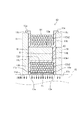
《完成断面及び放熱構造》
図3は、図1の(c)の状態におけるチョークコイル10に、放熱のための構成を付加して示す断面図である。ボビン13の挿入により位置決め部13cが外コア11の上部の端面11cに当たれば、そこが、正確な装着位置である。この装着位置で、内コア12の中心軸Aは、外コア11の平面11bの中心(図3の紙面の上下方向の中心、及び、紙面に直交する奥行き方向の中心)にある。このようにして、容易に、内コア12の中心軸Aを2平面11bの中心に合わせることができ、これにより、磁束をバランスよく外コア11に通すことができる。
《Complete cross section and heat dissipation structure》
FIG. 3 is a cross-sectional view showing the
また、図3において、内コア12の中心軸A方向の左端部は、外コア11の一方(左方)の平面11bに当接し、右端部は有底穴13dの底の厚さ(図2のt2)を介して他方(右方)の平面11bに対向する。すなわち、内コア12をボビン13の有底穴13dに挿入して所定の位置に収めた状態で、ボビン13を外コア11の枠内に装着すれば、内コア12の一端は外コア11に当接させ、他端は外コア11との間に、底の厚さ(t2)で規定される一定のギャップを設けることができる。これにより、ギャップの寸法管理が容易になる。
3, the left end portion of the
また、図3において、コイル14の最外層の一部(下方にある部分)14aは、外コア11の枠の端面11d側に露出し、かつ、端面11dよりも外コア11の内方(図の上方)にある。そこで、外コア11の端面11d及びコイル14の最外層の一部14aに対向する放熱部材15を設ける。この放熱部材15とは例えばウォータージャケット構造で、熱を吸収し、搬出することができるものである。外コアの11の下方の端面11dには、この放熱部材15が当接する。また、コイル14の最外層の一部14aと放熱部材15との間に、放熱シート16を挟み込み、固定する。放熱シート16は、熱伝導性に優れ、柔軟性のあるシート状の熱伝導材である。
Further, in FIG. 3, a part (lower part) 14 a of the outermost layer of the
このような放熱のための構成により、外コア11に関しては端面11dを放熱部材15に接触させることにより容易に放熱用熱伝導経路を構成することができる。また、コイル14に関しては最外層の一部14aを、放熱シート16を介して放熱部材15に接触させることにより最短の(外コア11経由でない)放熱用熱伝導経路を構成することができる。従って、図3の矢印で示すように、コイル14の発生する熱を、外コア11経由のみならず、コイル14の最外層から放熱部材15に伝導させることができる点で、優れた放熱効果が得られる。
With such a structure for heat dissipation, a heat conduction path for heat dissipation can be easily configured by bringing the
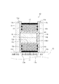
図4は、図3に示した放熱シート16とは異なる他の、放熱のための構成を設けた例を示す断面図である。図において、コイル14全体及びボビン13は、外コア11の枠の両端面間に例えばエポキシ樹脂を充填することによりモールドされる。このモールドによって、外コア11内の空間部分はエポキシ樹脂で満たされ、上下の端面13c,13eと同じ平面にモールド部17の表面がある状態(チョークコイル全体の外面にモールド部17の表面が出ている状態)となる。
FIG. 4 is a cross-sectional view illustrating an example in which a configuration for heat dissipation other than the
図6は、あくまで参考用の比較例として、図1に示すチョークコイルとは全く異なる構成のチョークコイルを示す図であり、(a)は主にコア配置を示す平面図、(b)は斜視図である。まず(a)において、このチョークコイル300は、コイル302が巻かれる一対の第1コア301と、第1コア301と四角形状を構成する一対の第2コア303とを備えている。このような構成のチョークコイル300は、(b)に示すように、例えばアルミニウム製のケース304に収められた状態とされる。ケース304の四隅には、取り付け用のねじを通す部位304aが、設けられている。
6 is a diagram showing a choke coil having a completely different configuration from the choke coil shown in FIG. 1 as a comparative example for reference only, (a) is a plan view mainly showing the core arrangement, and (b) is a perspective view. FIG. First, in (a), the
図7は、比較のために従来の製造方法(特にモールド方法)を示す斜視図である。実装面305(放熱部材)上のねじ孔(図示せず。)を利用してねじ止めされたモールド用のケース304内には、コア301,303及びコイル302が収容されている。この状態で、ケース304内に、溶融状態の樹脂Rを流し込み、樹脂Rが固化して、コア301,303及びコイル302をモールドする。
FIG. 7 is a perspective view showing a conventional manufacturing method (particularly a molding method) for comparison.
一方、図8は、本実施形態のチョークコイル10を実装面である放熱部材15に固定した状態を示す斜視図である。(a)において、まず、放熱部材15に、外コア11の枠の一端面を置いて、例えば板バネ製のサドル型の取付具21を取り付ける。この取付具21をねじ止めすることにより、チョークコイル10を放熱部材15に固定することができる。ここで、溶融状態の樹脂Rを外コア11の内側に流し込む。(b)に示すように、樹脂が固化すれば、コイル14及びボビン13をモールドするモールド部17が出来上がる。なお、樹脂が放熱部材15にも張り付くことにより一定の固定効果は得られるが、取付具21を取り付けることが、より好ましい。
On the other hand, FIG. 8 is a perspective view showing a state in which the
上記の製造(特にモールド)方法によれば、外コア11が磁路の一部でありながら、樹脂の容器の機能を兼ね備える。すなわち、チョークコイル10を放熱部材15等の実装面に実装する際、外コア11とその実装面とがモールドの型枠代わりになり、樹脂充填の容器となる。従って、別途、モールドのケースを設ける必要が無い。こうして、外コア11を型枠として利用したモールド部17を容易に形成することができる。
According to the manufacturing (particularly molding) method described above, the
ここで、外コア11の下方におけるモールド部17の表面(図8では下面)を放熱部材15に接触させることにより、コイル14の熱を放熱部材15に導く最短の(外コア11経由でない)放熱用熱伝導経路を構成することができる。従って、コイル14の発生する熱を、外コア11経由のみならず、モールド部17を介して放熱部材15に伝導させることができる点で、優れた放熱効果が得られる。
Here, by bringing the surface (the lower surface in FIG. 8) of the
《まとめ》
以上のように、上記実施形態のチョークコイル10によれば、外コア11と内コア12とが互いに別部材であることによって各々は形状が単純化され、外コア11は方形枠状で、内コア12は心棒状であるので、共に形状が簡素で成形が容易である。また、形状が簡素であることにより局部的な応力集中を抑制でき、ダストコアであっても機械的強度の確保が容易である。また、方形枠状の外コア11及び心棒状の内コア12は、それぞれ、外コア11の枠形状及び内コア12の中心軸方向に直交する断面形状が任意の断面で一定不変であるので、各コアのプレス成形が容易である。
<Summary>
As described above, according to the
また、内コア12は、ボビン13の中央に形成された穴(有底穴13d)に挿入されて所定の位置に収められることによって、内コア12の中心軸Aの方向の一端部が外コア11の2平面11bのうち一方の平面に当接し、他端部は、磁気的な所定のギャップ(図2の厚さt2に相当)を形成しつつ他方の平面に対向する。すなわち、内コア12をボビン13の穴に挿入して所定の位置に収めたものを、外コア11の枠内に装着すれば、内コア12の一端は外コア11に当接させ、他端は外コア11との間に、所定のギャップを設けることができる。これにより、ギャップの寸法管理が容易になる。
Further, the
また、ボビン13においてコイル14を巻き付ける部位(芯体13a)の、巻回軸方向に直交する断面形状は楕円であり、これは、断面形状が四角形等の多角形である場合と比べると角が無いのでコイル14を当該部位に密着させ易い。また、断面形状が円である場合と比べると巻き方向に曲率の変化があるので、巻き付けたコイル14が緩みにくい。従って、コイル14の巻き付けが容易である。なお、内コア12も相似な形状の楕円とすることで、コイル14と内コア12との距離を、コイル一周あたりで均一にすることができる。
In addition, the cross-sectional shape perpendicular to the winding axis direction of the part (
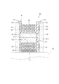
なお、上記実施形態において、外コア11は内外面ともに方形であるが、外面は必ずしも方形でなくてもよい。例えば、図9に示す変形例の外コア11は、内面は図1と同様に一対2組の平面11a,11bを有する方形であるが、外面は円弧状に膨らませた形状となっている。この場合も、形状が簡素であることによる基本的な作用効果は同様であり、肉厚を増した分や、外面の丸みにより、機械的強度も向上することが期待される。
また、図1及び図9の外コア11の内面側の方形の四隅に、ボビン13の鍔部13bの肉厚分に相当する曲率半径の丸みを設けてもよい。
In the above embodiment, the
Moreover, you may provide the roundness of the curvature radius corresponded to the thickness part of the
《内コア及びボビンの芯体についての他の形態》
また、上記実施形態において、図1に示すボビン13の芯体13a及び内コア12の断面形状は楕円とした。これは前述のようにコイル14を巻き付け易い利点がある。しかしながら、断面形状は楕円に限定されない。例えば、円も可能であり、円や楕円に近似した曲線でもよい。また、長方形等の多角形でも、角を円弧状に丸めた輪郭とすれば好適である。
<< Other forms of inner core and bobbin core >>
Moreover, in the said embodiment, the cross-sectional shape of the
総括的には、ボビン13の芯体及び内コア12の断面形状(輪郭)は、円及び楕円を含む、丸みを帯びた外側に凸な曲線、又は、角を丸めた多角形であればよい。これらの形状は、断面形状が四角形等の、角のある多角形である場合と比べると、角が無いのでコイルを密着させ易い。また、長方形の角を丸めた形状は、巻き方向に辺の長さの変化があるので、巻き付けたコイルが緩みにくい。従って、コイルの巻き付けが容易である。
なお、前述のように、芯体13aの断面形状と、内コア12の断面形状とは、互いに相似の関係にすることが、コイル14と内コア12との間の磁気的な距離の均一性を維持するために好適である。
In general, the cross-sectional shape (contour) of the core body of the
As described above, the cross-sectional shape of the
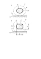
図10は、内コア12及びボビン13の芯体13aの断面形状の2つの例を示す概略図である。(a)に示すように、図1に示したような断面形状が楕円の内コア12及び芯体13aの場合、コイル14を巻くのは容易であるが、コイル14の最外周部が放熱シート16に直接接触する面積が小さく、コイル14から放熱シート16への直接の放熱性は、さほど良くない。これは、断面形状が円であっても同じである。断面形状を長方形にすれば、コイル14を、広い面積にわたって放熱シート16に接触させることができるが、角があると、コイル14を巻き付けるのが容易でない。
FIG. 10 is a schematic diagram showing two examples of cross-sectional shapes of the core 13a of the
そこで、(b)に示すように、断面形状は、長方形を基調として、角を丸めた形態が、より好適である。この場合、コイル14を、広い面積にわたって放熱シート16に接触させることができるとともに、コイル14の巻き付けも容易である。
Therefore, as shown in (b), it is more preferable that the cross-sectional shape is based on a rectangle and rounded corners. In this case, the
《内コア等についての他の形態》
図11は、内コア12についての他の構成を示す斜視図である。上記実施形態では、内コア12を1本の心棒状(図1)に形成したが、図11に示すように中心軸Aの軸方向に分割して、それらの間にスペーサ18を挟む構成としてもよい。これは2分割の例であるが、3分割あるいはそれ以上に分割することも可能である。この場合、スペーサ18を、例えば非磁性体である樹脂製とすることにより、スペーサ18の厚さで磁気的なギャップを確保することができる。
<< Other forms of inner core, etc. >>
FIG. 11 is a perspective view showing another configuration of the
すなわち、この場合、図2,図3に示したようにボビン13の構造によって磁気的なギャップを確保することは必ずしも必要では無くなるので、ボビン13の有底穴13dは貫通穴に変更し、内コア12の両端面を外コア11に当接させる構成とすることも可能である。但し、図2に示すようなボビン13の有底穴13dの底の厚さでギャップを確保する構成と、内コア12にスペーサ18を挟む図11のような構成とを、併用してもよい。その場合には、有底穴13dの底の厚さとスペーサ18の厚さとの合計にて、必要量の磁気的なギャップを確保することになる。また、スペーサ18は、必ずしも非磁性体でなくてもよい。例えば、磁性体ではあるが、内コア12よりも磁気抵抗の大きい材質を選択することによって、ギャップに近似した作用(磁気飽和抑制)を持たせることもできる。
That is, in this case, as shown in FIGS. 2 and 3, it is not always necessary to secure a magnetic gap by the structure of the
《ボビンについての他の形態》
図12は、他の形態に係るボビン13を示す斜視図である。基本的な特徴として、ボビン13が芯体13a及びその両端の鍔部によって構成されている点、芯体13aに有底穴13dが形成されている点、及び、鍔部に位置決め部13cが形成されている点は、図1のボビン13と同様である。但し、芯体13aの断面形状(輪郭)は楕円ではなく、図10の(b)に示したような四隅を丸めた長方形である例を示している。
《Other forms of bobbins》
FIG. 12 is a perspective view showing a
図1に示すボビン13との主要な違いは、まず、一方の鍔部13bより他方の鍔部13fの方が、厚肉になっている点、及び、その鍔部13fに、その他の面より低くなる凹部13gが形成されている点である。鍔部13fの厚さに余裕があることによって、このような凹部13gを容易に形成することができる。この凹部13g及びその端壁13hにコイル14の巻端を沿わせることにより、コイル14の巻き付けが容易になる。
The main difference from the
図13は、図12におけるXIII−XIII線断面図である。有底穴13dの底が厚さt2の磁気的なギャップを構成する点は、図2と同様であるが、このギャップ側の鍔部13fは、厚さが例えばt3であり、左側の鍔部13bの厚さt1より分厚い。
13 is a cross-sectional view taken along line XIII-XIII in FIG. The bottom of the bottomed
図14は、図10に示すボビン13にコイル14を巻回したものを、外コア11内に装着した状態を示す部分断面図である。図中の矢印付きの線は、内コア12から外コア11へ流れ込むべき磁束が外側へ漏れて、漏れ磁束φとなっている状態を示している。コイル14の内周・右端寄りの電線がこのような漏れ磁束φを浴びると、電線に渦電流損が発生する。従って、なるべく漏れ磁束φを浴びないようにするのが好ましいのであるが、ギャップ側の鍔部13fを分厚くしたことによって、その分、漏れ磁束φから離れるように電線が左方へ引いた形となり、結果的に、電線が浴びる漏れ磁束の量が少なくなる。従って、チョークコイル10の損失が低減される。
14 is a partial cross-sectional view showing a state in which the
図15は、さらに他の形態に係るボビン13を示す図であり、(a)は断面図、(b)は鍔部13f側から見た側面図である。このボビン13は、内コアを収容する穴13jの底が抜けており、底孔13kが形成されている。なお、ここでは一例として、内コアは円柱状であり、穴13jも、それに対応した形状であるとする。底孔13kの直径は、穴13jの内径より小さく、従って、底孔13kの縁13k1が、内コアを当接させるストッパとなる。また、縁13k1の厚さ(t2)により、磁気的なギャップが形成される。このような底孔13kを形成することによって、ボビン13にコイルを巻く際にボビン13の回転軸となる治具を通すことができる利点が生じる。コイルを巻回した後の底孔13kの空間は、何も入れずに空間として存置してもよいし、放熱材や樹脂を充填してもよい。
15A and 15B are views showing a
なお、ボビン13の鍔部13b(位置決め部13cも含む。)又は13fは、外コア11への安定装着や位置決めの便宜、さらには放熱性向上のためには、図1,図12,又は図15の形状(四角い形状)が好適であるが、図20に示したような環状鍔部(102a)を有するボビン(内コアは円柱状)も採用可能ではある。この場合も、外コアと内コアとが互いに別部材であることによって各々は形状が単純化され、成形が容易であり、ダストコアであっても機械的強度の確保が容易である、という基本的作用効果は得られる。
The
《ボビンの固定》
図16は、図15のタイプのボビン13を用いた場合の、チョークコイル10の断面図である。ボビン13は本来、外コア11内への緊密な装着によって、安定して外コア11に保持される。また、位置決め部13cの存在によって図の下方向には動かない。しかし、より確実に外コア11とボビン13とを相互に固定するには、接着剤19の塗布後に外コア11にボビン13を挿入することが好ましい。接着剤としては、シリコン系が好ましいが、エポキシ系も使用可能である。
《Bobbin fixing》
FIG. 16 is a sectional view of the
《ボビンのさらに他の形態》
図17は、さらに他の形態のボビン13を示す斜視図である。(a)は、ボビンの単体図、(b)は、コイル14を巻回したボビン13が、外コア11に装着された状態を示す斜視図である。(a)において、ボビン13の鍔部13bは、上端から外側に折り返して下方へ突出した構造となっていて、外側の下端には固定用部位13mが設けられている。この固定用部位13mは、ねじを通すことができる孔13m1を備えている。これらの固定用部位13mを利用して放熱部材15にチョークコイル10を、固定することができる。また、その後、図8の要領により、樹脂によりモールド部17を形成することができる。この場合、図8のような取付具21は不要となる。
<Still other forms of bobbins>
FIG. 17 is a perspective view showing a
図18は、図17のボビン13の外側部分を少し短くした例である。(a)は、ボビンの単体図、(b)は、コイル14を巻回したボビン13が、外コア11に装着された状態を示す斜視図である。このように、放熱部材15から取付座15aを立設している場合は、ボビン13の固定用部位13mを高い位置にしたこのような構成が適する場合もある。
FIG. 18 is an example in which the outer portion of the
《コイルの種類》
図19は、コイルの断面形状の種類を示す図である。図2その他に示したコイル14の電線(絶縁電線)は、(a)に示すように、断面が円形の丸線であるが、その他、(b)に示すような断面が正方形状の平角線コイル14fや、(c)に示すような、断面が長方形状の平角線の短辺を内径面として巻いたエッジワイズコイル14wも使用可能である。エッジワイズコイルは、(a)の丸線、(b)の平角線に比べて巻きにくいが、占積率が大きく、大電流には好適である。
《Coil type》
FIG. 19 is a diagram showing types of cross-sectional shapes of coils. The electric wire (insulated electric wire) of the
《その他》
なお、今回開示された実施の形態はすべての点で例示であって制限的なものではないと考えられるべきである。本発明の範囲は特許請求の範囲によって示され、特許請求の範囲と均等の意味及び範囲内での全ての変更が含まれることが意図される。
<Others>
The embodiment disclosed this time should be considered as illustrative in all points and not restrictive. The scope of the present invention is defined by the terms of the claims, and is intended to include any modifications within the scope and meaning equivalent to the terms of the claims.
10 チョークコイル
11 外コア
11b 平面
11d 端面
12 内コア
13 ボビン
13a 芯体
13b,13f 鍔部
13c 位置決め部
13d 有底穴
13g 凹部
13j 穴
13m 固定用部位
14 コイル
15 放熱部材
17 モールド部
18 スペーサ
DESCRIPTION OF
Claims (12)
コイルが巻回された状態で前記外コアの枠内に装着されたボビンと、
前記ボビンの磁心となるダストコアであって、前記コイルの巻回軸方向と平行な中心軸を有する心棒状の形状を有し、当該中心軸が前記外コアの内面で互いに対向する2平面に直交する方向となるように当該2平面間に介挿されている内コアと、
前記外コアを型枠として、枠の両端面間に樹脂を充填して成り、前記コイル及び前記ボビンをモールドするモールド部と
を備えていることを特徴とするチョークコイル。 A dust core, at least an outer core having a rectangular frame shape on the inner surface side;
A bobbin mounted in a frame of the outer core in a state where a coil is wound;
A dust core which is a magnetic core of the bobbin, has a mandrel-like shape having a central axis parallel to the winding axis direction of the coil, and the central axis is orthogonal to two planes facing each other on the inner surface of the outer core. An inner core interposed between the two planes so as to be in a direction to
A choke coil comprising: the outer core as a mold, and a resin portion filled between both end faces of the frame; and a mold portion for molding the coil and the bobbin.
前記コイルが巻回された状態の前記ボビンを前記外コアの枠内に装着し、その際、前記内コアの中心軸が前記外コアの内面で互いに対向する2平面に直交する方向となるように当該2平面間に前記内コアを介挿し、
平面上に前記外コアの枠の一端面を載せ、
他端面側から、枠の両端面間に樹脂を充填し、前記コイル及び前記ボビンをモールドする、
ことを特徴とするチョークコイルの製造方法。 An outer core having a rectangular frame shape at least on the inner surface side, a bobbin around which the coil is wound, and a dust core serving as a magnetic core of the bobbin, the center being parallel to the winding axis direction of the coil An inner core having a mandrel-like shape having a shaft, and a manufacturing method thereof for a choke coil comprising:
The bobbin in a state where the coil is wound is mounted in the frame of the outer core, and at this time, the central axis of the inner core is in a direction orthogonal to two planes facing each other on the inner surface of the outer core. Inserting the inner core between the two planes,
Place one end face of the outer core frame on a plane,
From the other end surface side, the resin is filled between both end surfaces of the frame, and the coil and the bobbin are molded.
A method for manufacturing a choke coil.
Priority Applications (1)
| Application Number | Priority Date | Filing Date | Title |
|---|---|---|---|
| JP2012152352A JP2013051402A (en) | 2011-08-01 | 2012-07-06 | Choke coil and manufacturing method of the same |
Applications Claiming Priority (3)
| Application Number | Priority Date | Filing Date | Title |
|---|---|---|---|
| JP2011168466 | 2011-08-01 | ||
| JP2011168466 | 2011-08-01 | ||
| JP2012152352A JP2013051402A (en) | 2011-08-01 | 2012-07-06 | Choke coil and manufacturing method of the same |
Publications (1)
| Publication Number | Publication Date |
|---|---|
| JP2013051402A true JP2013051402A (en) | 2013-03-14 |
Family
ID=47628927
Family Applications (2)
| Application Number | Title | Priority Date | Filing Date |
|---|---|---|---|
| JP2013526767A Pending JPWO2013018381A1 (en) | 2011-08-01 | 2012-01-20 | choke coil |
| JP2012152352A Pending JP2013051402A (en) | 2011-08-01 | 2012-07-06 | Choke coil and manufacturing method of the same |
Family Applications Before (1)
| Application Number | Title | Priority Date | Filing Date |
|---|---|---|---|
| JP2013526767A Pending JPWO2013018381A1 (en) | 2011-08-01 | 2012-01-20 | choke coil |
Country Status (5)
| Country | Link |
|---|---|
| US (1) | US20140176291A1 (en) |
| JP (2) | JPWO2013018381A1 (en) |
| CN (1) | CN103733283A (en) |
| DE (1) | DE112012003217T5 (en) |
| WO (1) | WO2013018381A1 (en) |
Cited By (11)
| Publication number | Priority date | Publication date | Assignee | Title |
|---|---|---|---|---|
| WO2014156770A1 (en) * | 2013-03-25 | 2014-10-02 | Ntn株式会社 | Electric circuit-use core and device using same |
| JP2015233033A (en) * | 2014-06-09 | 2015-12-24 | パナソニックIpマネジメント株式会社 | Coil structure and power supply device |
| WO2016027569A1 (en) * | 2014-08-20 | 2016-02-25 | 日立オートモティブシステムズ株式会社 | Reactor and dc-dc converter using same |
| JP2016066650A (en) * | 2014-09-24 | 2016-04-28 | 長野日本無線株式会社 | Coil device |
| JP2016171099A (en) * | 2015-03-11 | 2016-09-23 | 三菱電機株式会社 | Reactor device |
| WO2017047740A1 (en) * | 2015-09-17 | 2017-03-23 | Ntn株式会社 | Magnetic element |
| JP2017059811A (en) * | 2015-09-17 | 2017-03-23 | Ntn株式会社 | Magnetic element |
| DE102016118415A1 (en) | 2015-09-30 | 2017-03-30 | Taiyo Yuden Co.,Ltd. | Coil component and method of making the same |
| JP2018018902A (en) * | 2016-07-26 | 2018-02-01 | 株式会社オートネットワーク技術研究所 | Reactor |
| JP2018133500A (en) * | 2017-02-16 | 2018-08-23 | スミダコーポレーション株式会社 | Reactor and manufacturing method thereof |
| WO2021199494A1 (en) * | 2020-03-31 | 2021-10-07 | スミダコーポレーション株式会社 | Winding bobbin |
Families Citing this family (16)
| Publication number | Priority date | Publication date | Assignee | Title |
|---|---|---|---|---|
| JP6287391B2 (en) * | 2014-03-14 | 2018-03-07 | オムロン株式会社 | Electronic device and power supply device including the same |
| US9799442B1 (en) * | 2014-08-18 | 2017-10-24 | Universal Lighting Technologies, Inc. | Magnetic core structures for magnetic assemblies |
| WO2016170927A1 (en) * | 2015-04-23 | 2016-10-27 | 日立金属株式会社 | Surface-mounted reactor and manufacturing method therefor |
| WO2017029914A1 (en) * | 2015-08-18 | 2017-02-23 | 株式会社デンソー | Reactor |
| JP6398907B2 (en) * | 2015-08-18 | 2018-10-03 | 株式会社デンソー | Reactor |
| JP2017041497A (en) * | 2015-08-18 | 2017-02-23 | 株式会社デンソー | Reactor |
| CN105355362A (en) * | 2015-10-20 | 2016-02-24 | 天津三源华能电力设备技术有限公司 | Internal structure of transformer tank |
| KR101759168B1 (en) | 2016-01-11 | 2017-07-19 | (주)창성 | The manufacturing method of a coil-embedded heat-radiating inductor using heat-radiating powder paste and soft-magnetic powder paste and the coil-embedded heat-radiating inductor manufactured thereby |
| CN112908613B (en) * | 2016-04-01 | 2022-12-27 | 株式会社村田制作所 | Common mode choke coil |
| KR102010256B1 (en) | 2016-05-24 | 2019-08-13 | 주식회사 아모그린텍 | Coil component |
| WO2018041764A1 (en) | 2016-08-29 | 2018-03-08 | Koninklijke Philips N.V. | Inductive device |
| KR102520719B1 (en) * | 2018-08-14 | 2023-04-12 | 삼성전자주식회사 | Inductor |
| CN109657386B (en) * | 2018-12-27 | 2023-04-07 | 燕山大学 | Design method of rectangular Helmholtz coil |
| SE545081C2 (en) * | 2021-06-18 | 2023-03-21 | Saab Ab | A weight reducing transformer arrangement comprising a shell and a core with three orthogonal axes |
| DE102021209140A1 (en) * | 2021-08-19 | 2023-02-23 | Zf Friedrichshafen Ag | Storage choke with modular inner cores for a DC-DC converter, DC-DC converter and vehicle |
| CN114776747B (en) * | 2022-03-15 | 2023-09-22 | 东北大学 | Composite hyperbolic corrugated sandwich structure for inhibiting vibration of lubricating oil tank of aero-engine and application thereof |
Citations (8)
| Publication number | Priority date | Publication date | Assignee | Title |
|---|---|---|---|---|
| JPH0330305A (en) * | 1989-06-27 | 1991-02-08 | Matsushita Electric Works Ltd | Electromagnetic device |
| JPH03180009A (en) * | 1989-12-08 | 1991-08-06 | Matsushita Electric Ind Co Ltd | Current transformer |
| JP2002217044A (en) * | 2001-04-18 | 2002-08-02 | Funai Electric Co Ltd | Transformer |
| JP2003100525A (en) * | 2001-09-21 | 2003-04-04 | Hitachi Media Electoronics Co Ltd | Transformer |
| JP2006294787A (en) * | 2005-04-08 | 2006-10-26 | Matsushita Electric Ind Co Ltd | Reactor |
| JP2008016670A (en) * | 2006-07-06 | 2008-01-24 | Hitachi Ltd | Magnetic powder, dust core, and manufacturing method thereof |
| JP2009231495A (en) * | 2008-03-21 | 2009-10-08 | Toyota Motor Corp | Reactor |
| JP2012129241A (en) * | 2010-12-13 | 2012-07-05 | Mitsubishi Electric Corp | Magnetic component and manufacturing method of the same |
Family Cites Families (13)
| Publication number | Priority date | Publication date | Assignee | Title |
|---|---|---|---|---|
| US3377602A (en) * | 1966-05-31 | 1968-04-09 | Eltra Corp | Core supporting structure having encapsulated coil thereon |
| JPH01270306A (en) * | 1988-04-22 | 1989-10-27 | Mitsubishi Electric Corp | Bobbin for winding |
| JP3182144B2 (en) * | 1989-10-18 | 2001-07-03 | 松下電工株式会社 | lighting equipment |
| JP3197606B2 (en) * | 1992-05-07 | 2001-08-13 | ティーディーケイ株式会社 | Variable inductance type coil device |
| US5382937A (en) * | 1992-07-30 | 1995-01-17 | Tdk Corporation | Coil device |
| JPH0935965A (en) * | 1995-07-18 | 1997-02-07 | Matsushita Electric Ind Co Ltd | Reactor |
| DE10155898A1 (en) * | 2001-11-14 | 2003-05-28 | Vacuumschmelze Gmbh & Co Kg | Inductive component and method for its production |
| US20030184423A1 (en) * | 2002-03-27 | 2003-10-02 | Holdahl Jimmy D. | Low profile high current multiple gap inductor assembly |
| JP2006032559A (en) * | 2004-07-14 | 2006-02-02 | Tdk Corp | Coil component |
| US7170385B2 (en) * | 2004-11-18 | 2007-01-30 | Simmonds Precision Products, Inc. | Inductive proximity sensor and method of assembling the same |
| JP4149435B2 (en) * | 2004-12-15 | 2008-09-10 | スミダコーポレーション株式会社 | High voltage transformer |
| JP4688833B2 (en) * | 2007-03-16 | 2011-05-25 | 株式会社神戸製鋼所 | Powder for dust core, dust core and method for producing the same |
| CN102074333B (en) * | 2009-11-24 | 2013-06-05 | 台达电子工业股份有限公司 | Magnetic core set made of mixed materials, magnetic element and manufacturing method |
-
2012
- 2012-01-20 DE DE112012003217.9T patent/DE112012003217T5/en not_active Withdrawn
- 2012-01-20 WO PCT/JP2012/051179 patent/WO2013018381A1/en active Application Filing
- 2012-01-20 CN CN201280038260.7A patent/CN103733283A/en active Pending
- 2012-01-20 JP JP2013526767A patent/JPWO2013018381A1/en active Pending
- 2012-01-20 US US14/236,312 patent/US20140176291A1/en not_active Abandoned
- 2012-07-06 JP JP2012152352A patent/JP2013051402A/en active Pending
Patent Citations (8)
| Publication number | Priority date | Publication date | Assignee | Title |
|---|---|---|---|---|
| JPH0330305A (en) * | 1989-06-27 | 1991-02-08 | Matsushita Electric Works Ltd | Electromagnetic device |
| JPH03180009A (en) * | 1989-12-08 | 1991-08-06 | Matsushita Electric Ind Co Ltd | Current transformer |
| JP2002217044A (en) * | 2001-04-18 | 2002-08-02 | Funai Electric Co Ltd | Transformer |
| JP2003100525A (en) * | 2001-09-21 | 2003-04-04 | Hitachi Media Electoronics Co Ltd | Transformer |
| JP2006294787A (en) * | 2005-04-08 | 2006-10-26 | Matsushita Electric Ind Co Ltd | Reactor |
| JP2008016670A (en) * | 2006-07-06 | 2008-01-24 | Hitachi Ltd | Magnetic powder, dust core, and manufacturing method thereof |
| JP2009231495A (en) * | 2008-03-21 | 2009-10-08 | Toyota Motor Corp | Reactor |
| JP2012129241A (en) * | 2010-12-13 | 2012-07-05 | Mitsubishi Electric Corp | Magnetic component and manufacturing method of the same |
Cited By (19)
| Publication number | Priority date | Publication date | Assignee | Title |
|---|---|---|---|---|
| WO2014156770A1 (en) * | 2013-03-25 | 2014-10-02 | Ntn株式会社 | Electric circuit-use core and device using same |
| JP2015233033A (en) * | 2014-06-09 | 2015-12-24 | パナソニックIpマネジメント株式会社 | Coil structure and power supply device |
| WO2016027569A1 (en) * | 2014-08-20 | 2016-02-25 | 日立オートモティブシステムズ株式会社 | Reactor and dc-dc converter using same |
| JP2016046277A (en) * | 2014-08-20 | 2016-04-04 | 日立オートモティブシステムズ株式会社 | Reactor and dc-dc converter using the same |
| US10784788B2 (en) | 2014-08-20 | 2020-09-22 | Hitachi Automotive Systems, Ltd. | Reactor and DC-DC converter using same |
| JP2016066650A (en) * | 2014-09-24 | 2016-04-28 | 長野日本無線株式会社 | Coil device |
| JP2016171099A (en) * | 2015-03-11 | 2016-09-23 | 三菱電機株式会社 | Reactor device |
| EP3352182A4 (en) * | 2015-09-17 | 2019-06-19 | NTN Corporation | Magnetic element |
| CN108028119A (en) * | 2015-09-17 | 2018-05-11 | Ntn株式会社 | Magnetic element |
| JP2017059811A (en) * | 2015-09-17 | 2017-03-23 | Ntn株式会社 | Magnetic element |
| WO2017047740A1 (en) * | 2015-09-17 | 2017-03-23 | Ntn株式会社 | Magnetic element |
| US11145450B2 (en) | 2015-09-17 | 2021-10-12 | Ntn Corporation | Magnetic element |
| DE102016118415A1 (en) | 2015-09-30 | 2017-03-30 | Taiyo Yuden Co.,Ltd. | Coil component and method of making the same |
| US10366819B2 (en) | 2015-09-30 | 2019-07-30 | Taiyo Yuden Co., Ltd. | Coil component and method of manufacturing the same |
| JP2018018902A (en) * | 2016-07-26 | 2018-02-01 | 株式会社オートネットワーク技術研究所 | Reactor |
| JP2018133500A (en) * | 2017-02-16 | 2018-08-23 | スミダコーポレーション株式会社 | Reactor and manufacturing method thereof |
| US11183329B2 (en) | 2017-02-16 | 2021-11-23 | Sumida Corporation | Reactor and method for producing the same |
| WO2021199494A1 (en) * | 2020-03-31 | 2021-10-07 | スミダコーポレーション株式会社 | Winding bobbin |
| JP7510601B2 (en) | 2020-03-31 | 2024-07-04 | スミダコーポレーション株式会社 | Winding bobbin |
Also Published As
| Publication number | Publication date |
|---|---|
| JPWO2013018381A1 (en) | 2015-03-05 |
| WO2013018381A1 (en) | 2013-02-07 |
| DE112012003217T5 (en) | 2014-07-03 |
| CN103733283A (en) | 2014-04-16 |
| US20140176291A1 (en) | 2014-06-26 |
Similar Documents
| Publication | Publication Date | Title |
|---|---|---|
| JP2013051402A (en) | Choke coil and manufacturing method of the same | |
| JP5626466B2 (en) | Reactor and manufacturing method thereof | |
| CN103189942B (en) | Reactor | |
| JP5867677B2 (en) | Reactor, converter and power converter | |
| JP5083258B2 (en) | Reactor | |
| JP6065609B2 (en) | Reactor, converter, and power converter | |
| JP5983942B2 (en) | Reactor, converter, and power converter | |
| JPWO2011089941A1 (en) | Reactor | |
| JP2009033051A (en) | Core for reactor | |
| JP2012209333A (en) | Reactor and manufacturing method of the same | |
| JP2008028290A (en) | Reactor device and assembly method thereof | |
| JP6048652B2 (en) | Reactor, converter, and power converter | |
| JP2010157599A (en) | Reactor | |
| JP2014239120A (en) | Reactor, core piece for reactor, converter, and power conversion device | |
| JP2013179264A (en) | Reactor, converter and power conversion device | |
| JP2013179186A (en) | Reactor, component for reactor, converter, and power conversion device | |
| WO2013168538A1 (en) | Reactor, converter, electric power conversion device, and manufacturing method for resin core piece | |
| JP2013179259A (en) | Reactor, converter and power conversion device, and core material for reactor | |
| JP6651879B2 (en) | Reactor | |
| JP2014229659A (en) | Inductor and method of manufacturing the same | |
| JP2012227288A (en) | Coil formed body, component for reactor, and the reactor | |
| JP2013026418A (en) | Reactor | |
| JP2016100538A (en) | choke coil | |
| JP2015188019A (en) | Gap member, magnetic core and reactor | |
| JP2013105854A (en) | Reactor |
Legal Events
| Date | Code | Title | Description |
|---|---|---|---|
| A621 | Written request for application examination |
Free format text: JAPANESE INTERMEDIATE CODE: A621 Effective date: 20150701 |
|
| A977 | Report on retrieval |
Free format text: JAPANESE INTERMEDIATE CODE: A971007 Effective date: 20160420 |
|
| A131 | Notification of reasons for refusal |
Free format text: JAPANESE INTERMEDIATE CODE: A131 Effective date: 20160426 |
|
| A02 | Decision of refusal |
Free format text: JAPANESE INTERMEDIATE CODE: A02 Effective date: 20161025 |