JP6048652B2 - Reactor, converter, and power converter - Google Patents
Reactor, converter, and power converter Download PDFInfo
- Publication number
- JP6048652B2 JP6048652B2 JP2012251581A JP2012251581A JP6048652B2 JP 6048652 B2 JP6048652 B2 JP 6048652B2 JP 2012251581 A JP2012251581 A JP 2012251581A JP 2012251581 A JP2012251581 A JP 2012251581A JP 6048652 B2 JP6048652 B2 JP 6048652B2
- Authority
- JP
- Japan
- Prior art keywords
- reactor
- magnetic
- core
- core portion
- magnetic powder
- Prior art date
- Legal status (The legal status is an assumption and is not a legal conclusion. Google has not performed a legal analysis and makes no representation as to the accuracy of the status listed.)
- Active
Links
Images


Classifications
-
- H—ELECTRICITY
- H01—ELECTRIC ELEMENTS
- H01F—MAGNETS; INDUCTANCES; TRANSFORMERS; SELECTION OF MATERIALS FOR THEIR MAGNETIC PROPERTIES
- H01F27/00—Details of transformers or inductances, in general
- H01F27/24—Magnetic cores
- H01F27/255—Magnetic cores made from particles
-
- H—ELECTRICITY
- H01—ELECTRIC ELEMENTS
- H01F—MAGNETS; INDUCTANCES; TRANSFORMERS; SELECTION OF MATERIALS FOR THEIR MAGNETIC PROPERTIES
- H01F3/00—Cores, Yokes, or armatures
- H01F3/10—Composite arrangements of magnetic circuits
- H01F3/14—Constrictions; Gaps, e.g. air-gaps
-
- H—ELECTRICITY
- H01—ELECTRIC ELEMENTS
- H01F—MAGNETS; INDUCTANCES; TRANSFORMERS; SELECTION OF MATERIALS FOR THEIR MAGNETIC PROPERTIES
- H01F37/00—Fixed inductances not covered by group H01F17/00
-
- H—ELECTRICITY
- H01—ELECTRIC ELEMENTS
- H01F—MAGNETS; INDUCTANCES; TRANSFORMERS; SELECTION OF MATERIALS FOR THEIR MAGNETIC PROPERTIES
- H01F3/00—Cores, Yokes, or armatures
- H01F3/10—Composite arrangements of magnetic circuits
- H01F2003/106—Magnetic circuits using combinations of different magnetic materials
-
- H—ELECTRICITY
- H01—ELECTRIC ELEMENTS
- H01F—MAGNETS; INDUCTANCES; TRANSFORMERS; SELECTION OF MATERIALS FOR THEIR MAGNETIC PROPERTIES
- H01F27/00—Details of transformers or inductances, in general
- H01F27/24—Magnetic cores
- H01F27/26—Fastening parts of the core together; Fastening or mounting the core on casing or support
- H01F27/263—Fastening parts of the core together
Description
本発明は、ハイブリッド自動車や電気自動車などの駆動源に電力を利用する車両に搭載される車載用DC−DCコンバータといった電力変換装置の構成部品などに利用されるリアクトル、このリアクトルを用いたコンバータ、およびこのコンバータを用いた電力変換装置に関する。 The present invention relates to a reactor used for components of a power conversion device such as an in-vehicle DC-DC converter mounted on a vehicle that uses electric power for a drive source such as a hybrid vehicle or an electric vehicle, a converter using the reactor, The present invention also relates to a power converter using this converter.
電圧の昇圧動作や降圧動作を行う回路の部品の一つに、リアクトルがある。リアクトルは、ハイブリッド自動車などの車両に搭載されるコンバータに利用される。そのリアクトルとして、例えば、特許文献1に示すものがある。
A reactor is one of the parts of a circuit that performs a voltage step-up operation or a voltage step-down operation. The reactor is used in a converter mounted on a vehicle such as a hybrid vehicle. As the reactor, for example, there is one shown in
特許文献1のリアクトルは、一対のコイル素子を有するコイルと、これらコイル素子の内部に挿通される環状の磁性コアとを備える。磁性コアは、コイル素子の内部に配置されるコイル配置部(内側コア部)と、コイル素子から露出する露出部(外側コア部)とを有する。そして、特許文献1では、外側コア部を内側コア部よりも高比透磁率とすることで、磁気飽和し難い磁性コア、即ち磁気飽和し難いリアクトルとしている。
The reactor of
近年、ハイブリッド自動車などの発展に伴い、リアクトルに供給される電流が大きくなる傾向にある。リアクトルに供給する電流が大きくなると、特許文献1の構造を有するリアクトルであっても磁気飽和する場合があり、その対策が望まれている。
In recent years, with the development of hybrid vehicles and the like, the current supplied to the reactor tends to increase. When the current supplied to the reactor is increased, even the reactor having the structure of
本発明は上記事情に鑑みてなされたものであり、その目的の一つは、従来よりも磁気飽和し難いリアクトルを提供することにある。また、本発明の別の目的は、本発明のリアクトルを用いたコンバータ、およびそのコンバータを用いた電力変換装置を提供することにある。 The present invention has been made in view of the above circumstances, and one of its purposes is to provide a reactor that is less magnetically saturated than in the past. Another object of the present invention is to provide a converter using the reactor of the present invention and a power converter using the converter.
本発明者は、上記課題を解決するために、内側コア部と外側コア部との間にギャップ材を介在させる構成を検討した。また、本発明者は、その検討の過程でリアクトルを外部環境から保護する構成にも着目した。その結果、ギャップ材の配置とリアクトルの保護を両立させることができる構成に想到し、本発明を完成させた。以下に、本発明のリアクトルを規定する。 In order to solve the above problems, the present inventor has studied a configuration in which a gap material is interposed between the inner core portion and the outer core portion. In addition, the present inventor also paid attention to the configuration for protecting the reactor from the external environment in the course of the study. As a result, the inventors have conceived a configuration that can achieve both the arrangement of the gap material and the protection of the reactor, thereby completing the present invention. Below, the reactor of this invention is prescribed | regulated.
本発明のリアクトルは、コイルと、コイルの内部に挿通される部分を有する磁性コアとを備え、磁性コアが、コイルの内部に配置された内側コア部、およびコイルから露出している外側コア部を有するリアクトルである。この本発明のリアクトルでは、リアクトルに備わる内側コア部が、樹脂中に磁性粉末を分散させた磁性粉末混合樹脂からなり、外側コア部の比透磁率が、内側コア部の比透磁率よりも大きくなっており、かつ外側コア部が後述するコア成形体の形態で用いられている。 The reactor of the present invention includes a coil and a magnetic core having a portion inserted into the coil, and the magnetic core is disposed inside the coil, and the outer core portion is exposed from the coil. It is a reactor which has. In the reactor of the present invention, the inner core portion provided in the reactor is made of a magnetic powder mixed resin in which magnetic powder is dispersed in the resin, and the relative permeability of the outer core portion is larger than the relative permeability of the inner core portion. The outer core portion is used in the form of a core molded body to be described later.
なお、本発明のリアクトルは、並列される一対のコイル素子を有するコイルを備えるリアクトル(後述する実施形態1を参照)であっても良いし、一つのコイル素子を有するコイルを備えるリアクトル(実施形態2を参照)であっても良い。また、本発明のリアクトルにおける「コイルの内側に配置される内側コア部」とは、少なくとも一部がコイルの内部に配置されている内側コア部を意味する。例えば、内側コア部の中央部分がコイルの内部に位置し、内側コア部の端部付近がコイルの外側に位置するような場合も「コイルの内側に配置される内側コア部」に含まれる。
In addition, the reactor of this invention may be a reactor (refer
本発明のリアクトルにおけるコア成形体は、外側コア部と、その外側コア部を保護するコアモールド部とを有する。コアモールド部は、外側コア部の外周面のうち、少なくとも次の二つの部分を覆う。
[1]リアクトルの外方に向いた部分(コアモールド部を剥いだときに、リアクトルの外観上から視認できる部分と言い換えても良い)
[2]内側コア部に対向する部分(コアモールド部を剥いだとしても、リアクトルの外観上から視認することはできない)
The core molding in the reactor of this invention has an outer core part and the core mold part which protects the outer core part. The core mold part covers at least the following two parts of the outer peripheral surface of the outer core part.
[1] A part facing outward from the reactor (in other words, a part that can be visually recognized from the appearance of the reactor when the core mold part is peeled off)
[2] The part facing the inner core part (even if the core mold part is peeled off, it cannot be visually recognized from the appearance of the reactor)
外側コア部の外周面における上記[1]、[2]以外の部分はコアモールド部に覆われていても良いし、覆われていなくても良い。コアモールド部で覆われていても良いし覆われていなくても良い部分として、具体的には、外側コア部のうち、リアクトルの設置対象に対向する底面を挙げることができる。 Portions other than the above [1] and [2] on the outer peripheral surface of the outer core portion may be covered with the core mold portion or may not be covered. Specific examples of the portion that may or may not be covered with the core mold portion include the bottom surface of the outer core portion that faces the installation target of the reactor.
上記本発明の構成によれば、外側コア部の外周面のうち、リアクトルの外方に向いた部分がコアモールド部で覆われているため、外側コア部を外部環境から保護することができる。また、本発明の構成では、コア成形体における外側コア部の外周面のうち、内側コア部に対向する部分もコアモールド部で覆われている。そのため、コア成形体と内側コア部とを組み合わせて磁性コアを形成すると、コアモールド部の一部が外側コア部と内側コア部との間に配置されて、磁性コアのギャップ材として機能するため、磁性コアを磁気飽和し難くできる。このように、本発明の構成によれば、磁気飽和し難く、かつ外部環境から保護されたリアクトルとすることができる。 According to the configuration of the present invention described above, the outer core portion of the outer peripheral surface of the outer core portion that faces outward from the reactor is covered with the core mold portion, so that the outer core portion can be protected from the external environment. Moreover, in the structure of this invention, the part which opposes an inner core part among the outer peripheral surfaces of the outer core part in a core molded object is also covered with the core mold part. Therefore, when a magnetic core is formed by combining the core molded body and the inner core portion, a part of the core mold portion is disposed between the outer core portion and the inner core portion and functions as a gap material for the magnetic core. The magnetic core can be made hard to be magnetically saturated. Thus, according to the structure of this invention, it can be set as the reactor which is hard to be magnetically saturated and was protected from the external environment.
本発明のリアクトルの一形態として、コア成形体は、内側コア部の端部を収納する凹部を備える形態を挙げることができる。 As one form of the reactor of this invention, the core molded object can mention the form provided with the recessed part which accommodates the edge part of an inner core part.
上記構成によれば、コア成形体の凹部に内側コア部の端部を嵌め込むだけで、外側コア部と内側コア部との相対的な位置決めを容易に行なうことができる。また、組み立てられたリアクトルにおいて、外側コア部と内側コア部との相対的な位置がずれることを効果的に抑制できる。 According to the said structure, the relative positioning of an outer core part and an inner core part can be easily performed only by inserting the edge part of an inner core part in the recessed part of a core molded object. Moreover, in the assembled reactor, it can suppress effectively that the relative position of an outer core part and an inner core part shifts | deviates.
本発明のリアクトルの一形態として、外側コア部のうち、リアクトルの設置対象に向いた底面には、コアモールド部が形成されていない形態とすることが挙げられる。 As one form of the reactor of this invention, it is mentioned that it is set as the form by which the core mold part is not formed in the bottom face which faced the installation object of a reactor among outer core parts.
外側コア部の底部にコアモールド部を設けないことで、外側コア部から冷却ベースなどの設置対象への放熱性、即ちリアクトルから外部への放熱性を高めることができる。 By not providing the core mold part at the bottom of the outer core part, the heat dissipation from the outer core part to the installation object such as the cooling base, that is, the heat dissipation from the reactor to the outside can be enhanced.
本発明のリアクトルの一形態として、内側コア部を構成する磁性粉末混合樹脂の磁性成分の含有量は、全体を100体積%としたとき、20体積%以上75体積%以下である形態を挙げることができる。 As one form of the reactor of this invention, content of the magnetic component of the magnetic powder mixed resin which comprises an inner core part mentions the form which is 20 volume% or more and 75 volume% or less when the whole is 100 volume%. Can do.
磁性粉末が20体積%以上であることで、比透磁率や飽和磁束密度などの磁気特性を確保し易い。磁性粉末が75体積%以下であると、樹脂との混合が行い易く、磁性粉末混合樹脂の製造性に優れる。このような内側コア部を磁性コアに用いれば、磁性コアを磁気飽和し難くできる。 When the magnetic powder is 20% by volume or more, it is easy to ensure magnetic properties such as relative permeability and saturation magnetic flux density. When the magnetic powder is 75% by volume or less, mixing with the resin is easy, and the productivity of the magnetic powder mixed resin is excellent. If such an inner core part is used for a magnetic core, the magnetic core can be hardly magnetically saturated.
本発明のリアクトルの一形態として、外側コア部は、圧粉成形体である形態を挙げることができる。 As one form of the reactor of this invention, the outer core part can mention the form which is a compacting body.
圧粉成形体における磁性成分の含有量は、磁性粉末混合樹脂における磁性成分の含有量よりも多くすることが容易であり、そのため圧粉成形体の比透磁率を、磁性粉末混合樹脂の比透磁率よりも大きくし易い。本発明のリアクトルでは、外側コア部の比透磁率が内側コア部の比透磁率よりも大きく、かつ内側コア部が磁性粉末混合樹脂からなることが必須要件であるため、外側コア部を圧粉成形体とすると、『外側コア部の比透磁率>内側コア部の比透磁率』の関係を容易に満たすことができる。 It is easy to increase the content of the magnetic component in the green compact to be higher than the content of the magnetic component in the magnetic powder mixed resin. Therefore, the relative permeability of the green compact is set to be the relative permeability of the magnetic powder mixed resin. It is easy to make it larger than the magnetic susceptibility. In the reactor of the present invention, it is essential that the relative permeability of the outer core portion is larger than the relative permeability of the inner core portion, and the inner core portion is made of a magnetic powder mixed resin. When the molded body is used, the relationship of “relative permeability of outer core portion> relative permeability of inner core portion” can be easily satisfied.
本発明のリアクトルの一形態として、外側コア部は、樹脂中に磁性粉末を分散させた磁性粉末混合樹脂である形態を挙げることができる。 As one form of the reactor of this invention, the outer core part can mention the form which is magnetic powder mixed resin which disperse | distributed magnetic powder in resin.
磁性粉末混合樹脂は、樹脂と磁性粉末の割合を変化させることで、その磁気特性を容易に変化させることができる。そのため、磁性粉末混合樹脂で外側コア部を構成すれば、所望の磁気特性を備える外側コア部を容易に得られる。 Magnetic powder mixed resin can easily change its magnetic characteristics by changing the ratio of resin and magnetic powder. Therefore, if an outer core part is comprised with a magnetic powder mixed resin, an outer core part provided with a desired magnetic characteristic can be obtained easily.
外側コア部が磁性粉末混合樹脂で構成される本発明のリアクトルの一形態として、外側コア部を構成する磁性粉末混合樹脂の磁性成分の含有量は、全体を100体積%としたとき、20体積%以上75体積%以下である形態を挙げることができる。 As one form of the reactor of the present invention in which the outer core portion is made of a magnetic powder mixed resin, the content of the magnetic component of the magnetic powder mixed resin constituting the outer core portion is 20 volumes when the whole is 100% by volume. The form which is% or more and 75 volume% or less can be mentioned.
上記範囲の磁性成分を含有する外側コア部を磁性コアに用いれば、磁性コアを磁気飽和し難くできる。 If the outer core portion containing the magnetic component in the above range is used for the magnetic core, the magnetic core can be hardly magnetically saturated.
本発明のリアクトルの一形態として、磁性コア全体の比透磁率を10以上50以下、内側コア部の比透磁率を5以上50以下、外側コア部の比透磁率を50以上500以下とすることが好ましい。磁性コア全体のさらに好ましい比透磁率は10以上35以下、最も好ましい比透磁率は10以上30以下である。ここで、磁性コア全体の比透磁率とは、内側コア部と、外側コア部と、コアモールド部のうちの外側コア部と内側コア部との間に配置されている部分と、を合わせた比透磁率である。さらに磁性コアにギャップ材が含まれる場合、例えば磁性粉末混合樹脂からなる複数の分割片と、分割片の間に配置されるギャップ材とで内側コア部が構成される場合、磁性コア全体の比透磁率は、そのギャップ材も含めた比透磁率である。 As one form of the reactor of the present invention, the relative permeability of the entire magnetic core is 10 or more and 50 or less, the relative permeability of the inner core part is 5 or more and 50 or less, and the relative permeability of the outer core part is 50 or more and 500 or less. Is preferred. The more preferable relative permeability of the entire magnetic core is 10 or more and 35 or less, and the most preferable relative permeability is 10 or more and 30 or less. Here, the relative magnetic permeability of the entire magnetic core is a combination of the inner core portion, the outer core portion, and the portion disposed between the outer core portion and the inner core portion of the core mold portion. The relative permeability. Furthermore, when the gap material is included in the magnetic core, for example, when the inner core portion is composed of a plurality of divided pieces made of a magnetic powder mixed resin and the gap material arranged between the divided pieces, the ratio of the entire magnetic core The magnetic permeability is a relative magnetic permeability including the gap material.
なお、ここでいう上記各コア部の比透磁率とは、次のようにして求めたものをいう。コア部と同じ材料で、外径34mm、内径20mm、厚さ5mmのリング状試験片を作製する。この試験片に、一次側300巻き、二次側20巻きの巻線を施して、試験片のB−H初磁化曲線をH=0〜100エルステッド(Oe)の範囲で測定する。この測定には、例えば、理研電子株式会社製BHカーブトレーサ「BHS−40S10K」を使用することができる。そして、得られたB‐H初磁化曲線の勾配(B/H)の最大値を求め、それをコア部の比透磁率とする。ここでの磁化曲線とは、いわゆる直流磁化曲線である。 In addition, the relative magnetic permeability of each said core part here means what was calculated | required as follows. A ring-shaped test piece having an outer diameter of 34 mm, an inner diameter of 20 mm, and a thickness of 5 mm is produced using the same material as the core portion. The test piece is subjected to winding of 300 turns on the primary side and 20 turns on the secondary side, and the BH initial magnetization curve of the test piece is measured in the range of H = 0 to 100 Oersted (Oe). For this measurement, for example, a BH curve tracer “BHS-40S10K” manufactured by Riken Denshi Co., Ltd. can be used. Then, the maximum value of the gradient (B / H) of the obtained BH initial magnetization curve is obtained and used as the relative permeability of the core portion. The magnetization curve here is a so-called DC magnetization curve.
一方、上記各コア部の飽和磁束密度は、上記試験片に対して電磁石で10000(Oe)の磁界を印加し、十分に磁気飽和させたときの磁束密度とする。 On the other hand, the saturation magnetic flux density of each of the core portions is the magnetic flux density when a magnetic field of 10,000 (Oe) is applied to the test piece with an electromagnet and sufficiently magnetically saturated.
上記範囲の比透磁率を満たす磁性コアは、リアクトルに利用した際に磁気飽和し難い。上記範囲の比透磁率は、外側コア部を圧粉成形体とすることで満たし易い。 A magnetic core satisfying the relative permeability in the above range is less likely to be magnetically saturated when used in a reactor. The relative magnetic permeability in the above range can be easily satisfied by using the outer core portion as a green compact.
本発明のリアクトルの一形態として、磁性コア全体の比透磁率を5以上30以下、内側コア部の比透磁率を5以上25以下、外側コア部の比透磁率を10以上40以下とすることが好ましい。 As one form of the reactor of the present invention, the relative permeability of the entire magnetic core is 5 or more and 30 or less, the relative permeability of the inner core part is 5 or more and 25 or less, and the relative permeability of the outer core part is 10 or more and 40 or less. Is preferred.
上記範囲の比透磁率を満たす磁性コアは、リアクトルに利用した際に磁気飽和し難い。上記範囲の比透磁率は、外側コア部を磁性粉末混合樹脂とすることで満たし易い。外側コア部を圧粉成形体としても上記範囲の比透磁率を満たすことは可能である。 A magnetic core satisfying the relative permeability in the above range is less likely to be magnetically saturated when used in a reactor. The relative permeability in the above range can be easily satisfied by using the outer core portion as a magnetic powder mixed resin. It is possible to satisfy the relative magnetic permeability in the above range even when the outer core portion is a green compact.
本発明のコンバータは、上記本発明のリアクトルを備える。例えば、本発明のコンバータとして、スイッチング素子と、上記スイッチング素子の動作を制御する駆動回路と、スイッチング動作を平滑にする本発明のリアクトルとを備え、上記スイッチング素子の動作により、入力電圧を変換する構成を挙げることができる。 The converter of this invention is provided with the reactor of the said invention. For example, the converter of the present invention includes a switching element, a drive circuit that controls the operation of the switching element, and the reactor of the present invention that smoothes the switching operation, and converts the input voltage by the operation of the switching element. A configuration can be mentioned.
本発明の電力変換装置は、上記本発明のコンバータを備える。例えば、本発明の電力変換装置として、入力電圧を変換する本発明のコンバータと、上記コンバータに接続されて、直流と交流とを相互に変換するインバータとを備え、このインバータで変換された電力により負荷を駆動する形態を挙げることができる。 The power converter device of this invention is provided with the converter of the said invention. For example, the power converter of the present invention includes a converter of the present invention that converts an input voltage, and an inverter that is connected to the converter and converts between direct current and alternating current, and the electric power converted by the inverter The form which drives load can be mentioned.
生産性に優れる本発明のリアクトルを用いた本発明のコンバータ、及び本発明の電力変換装置は、これらを備える機器(例えば、ハイブリット自動車などの車両)の生産性の向上に寄与する。 The converter of the present invention using the reactor of the present invention that is excellent in productivity and the power conversion device of the present invention contribute to the improvement of the productivity of equipment (for example, a vehicle such as a hybrid car) provided with these.
本発明のリアクトルは、磁気飽和し難い。 The reactor of the present invention is hardly magnetically saturated.
以下、本発明の実施形態をより具体的に説明する。図中の同一符号は同一名称物を示す。 Hereinafter, embodiments of the present invention will be described more specifically. The same reference numerals in the figure indicate the same names.
<実施形態1>
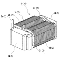
図1〜3に示す本実施形態1のリアクトル1は、コイル2と磁性コア3との組合体10である。このリアクトル1のコイル2は一対のコイル素子2A,2Bを有し、磁性コア3は一対の内側コア部31,31と一対の外側コア部32,32とを備える(特に、図3を参照)。このリアクトル1の特徴とするところは、図3に示すように、外側コア部32の外周面に、外側コア部32を保護するコアモールド部5Mが形成され、かつこのコアモールド部5Mのうち、外側コア部32と内側コア部31との間に配置される部分がギャップ材として機能することである。以下、本実施形態1のリアクトル1の各構成を詳細に説明する。
<
A
≪コイル≫
組合体10(リアクトル1)に備わるコイル2は、一対のコイル素子2A,2Bと、両コイル素子2A,2Bを連結するコイル素子連結部2rとを備える。各コイル素子2A,2Bは、互いに同一の巻数、同一の巻回方向で中空筒状に形成され、各軸方向が平行するように横並びに並列されている。本実施形態では、これらコイル素子2A,2Bは接続部の無い一本の巻線を螺旋状に巻回することで形成されており、その巻線をU字状に屈曲させることで上記コイル素子連結部2rが形成されている。もちろん、両コイル素子2A,2Bは、別個の巻線を螺旋状に巻回することで形成しても良く、その場合、例えば、コイル素子2A,2Bの端部同士を圧接や溶接などで接合する。
≪Coil≫
The
コイル2は、銅やアルミニウム、その合金といった導電性材料からなる平角線や丸線などの導体の外周に、絶縁性材料からなる絶縁被覆を備える被覆線を好適に利用できる。本実施形態では、導体が銅製の平角線からなり、絶縁被覆がエナメル(代表的にはポリアミドイミド)からなる被覆平角線を利用し、各コイル素子2A,2Bは、この被覆平角線をエッジワイズ巻きにしたエッジワイズコイルである。また、各コイル素子2A,2Bの端面形状を長方形の角部を丸めた形状としているが、端面形状は、円形状など適宜変更することができる。
As the
コイル2の両端部2a,2b(図1、図3の紙面左側)は、ターン形成部分から引き延ばされて、図示しない端子部材に接続される。この端子部材を介して、コイル2に電力供給を行なう電源などの外部装置(図示せず)が接続される。
Both
≪磁性コア≫
組合体10(リアクトル1)に備わる磁性コア3は、各コイル素子2A,2Bの内部に配置される一対の内側コア部31,31と、コイル素子2A,2Bから露出し、内側コア部31,31をその両側から挟み込む一対の外側コア部32,32(特に、図3の点線丸囲みを参照)とを備える。そして、外側コア部32の比透磁率は、内側コア部31の比透磁率よりも高い。このように両コア部31,32の比透磁率を異ならせることで、磁性コア3全体の比透磁率を調整し、磁性コア3を磁気飽和し難くできる。ここで、本発明のリアクトル1では、後段で詳述するように外側コア部32の外周面に形成されるコアモールド部5Mが、内側コア部31と外側コア部32との間でギャップ材として機能し、磁性コア3をさらに磁気飽和し難くしている。
≪Magnetic core≫
The
磁性コア3全体と、磁性コア3を構成する各コア部31,32の好ましい比透磁率の一例を以下に示す。
・磁性コア3全体…比透磁率=10以上50以下、より好ましくは10以上35以下、さらに好ましくは10以上30以下
・内側コア部31…比透磁率=5以上50以下
・外側コア部32…比透磁率=50以上500以下
An example of preferable relative magnetic permeability of the entire
The entire
〔内側コア部〕
磁性コア3を構成する内側コア部31,31は、繋ぎ目がない一本の柱状体であって、樹脂中に磁性粉末を分散させた磁性粉末混合樹脂で構成されている。内側コア部31,31を磁性粉末混合樹脂で構成したのは、磁性粉末混合樹脂がその構成上、低比透磁率体にし易いからである。
[Inner core]
The
(磁性粉末混合樹脂)
内側コア部31を構成する磁性粉末混合樹脂は、代表的には、バインダとなる樹脂に磁性粉末を混合したものである。磁性粉末には、鉄基材料や希土類金属などの軟磁性材料、これら軟磁性材料に絶縁被覆を備える被覆粉末などを利用できる。特に、被覆粉末を用いることで、磁性粉末混合樹脂における渦電流損を効果的に低減することができる。絶縁被覆としては、例えば、リン酸化合物、珪素化合物、ジルコニウム化合物、アルミニウム化合物、硼素化合物などが挙げられる。一方、バインダとなる樹脂には、例えば、エポキシ樹脂、フェノール樹脂、シリコーン樹脂、ウレタン樹脂などの熱硬化性樹脂を用いることができる。その他、ポリフェニレンスルフィド(PPS)樹脂、ポリイミド樹脂、フッ素樹脂などの熱可塑性樹脂、常温硬化性樹脂、あるいは低温硬化性樹脂を用いてもよい。また、不飽和ポリエステルに炭酸カルシウムやガラス繊維が混合されたBMC(Bulk molding compound)や、ミラブル型シリコーンゴム、ミラブル型ウレタンゴムなどを用いることもできる。
(Magnetic powder mixed resin)
Typically, the magnetic powder mixed resin constituting the
磁性粉末混合樹脂で内側コア部31,31を形成する場合、代表的には、射出成形、トランスファー成形、MIM(Metal Injection Molding)、注型成形、磁性粉末と粉末状の固形樹脂とを用いたプレス成形などを利用することができる。射出成形の場合は、磁性粉末と樹脂との混合材料を所定の圧力をかけて成形型に充填して成形した後、上記樹脂を硬化させることで磁性粉末混合樹脂を得ることができる。トランスファー成形やMIMの場合も、上記混合材料を成形型に充填して成形を行う。注型成形の場合は、上記混合材料を、圧力をかけることなく成形型に注入して成形・硬化させることで磁性粉末混合樹脂を得ることができる。
When the
磁性粉末混合樹脂における磁性粉末の平均粒径は、1μm以上1000μm以下、特に10μm以上500μm以下とすることが好ましい。また、磁性粉末は、粒径が異なる複数種の粉末が混合されたものでも良い。平均粒径が上記範囲を満たす磁性粉末を材料に用いると、流動性が高く、射出成形などを利用して磁性粉末混合樹脂を生産性良く製造できる。 The average particle size of the magnetic powder in the magnetic powder mixed resin is preferably 1 μm or more and 1000 μm or less, and particularly preferably 10 μm or more and 500 μm or less. The magnetic powder may be a mixture of a plurality of types of powders having different particle sizes. When a magnetic powder having an average particle size satisfying the above range is used as a material, the fluidity is high, and a magnetic powder mixed resin can be produced with high productivity using injection molding or the like.
その他、磁性粉末混合樹脂には、磁性粉末及び樹脂に加えて、アルミナやシリカなどのセラミックスといった非磁性材料からなる粉末(フィラー)が含有されていても良い。フィラーは、放熱性の向上、磁性粉末の偏在の抑制(均一的な分散)に寄与する。また、フィラーが微粒であり、磁性粒子間に介在することで、フィラーの含有による磁性粉末の割合の低下を抑制できる。フィラーの含有量は、磁性粉末混合樹脂を100質量%とするとき、0.2質量%以上20質量%以下、更に0.3質量%以上15質量%以下、特に0.5質量%以上10質量%以下であると、上記効果を十分に得られる。 In addition to the magnetic powder and resin, the magnetic powder mixed resin may contain powder (filler) made of a nonmagnetic material such as ceramics such as alumina or silica. The filler contributes to improvement in heat dissipation and suppression of uneven distribution of magnetic powder (uniform dispersion). Moreover, since the filler is fine and intervenes between the magnetic particles, a decrease in the ratio of the magnetic powder due to the inclusion of the filler can be suppressed. The content of the filler is 0.2% by mass or more and 20% by mass or less, further 0.3% by mass or more and 15% by mass or less, particularly 0.5% by mass or more and 10% by mass or less when the magnetic powder mixed resin is 100% by mass. When the content is less than or equal to%, the above effect can be sufficiently obtained.
磁性粉末混合樹脂は、磁性粉末混合樹脂における磁性粉末の含有量は、磁性粉末混合樹脂を100%とするとき、体積割合で20体積%以上75体積%以下とすることが好ましい。磁性粉末が20体積%以上であることで、比透磁率や飽和磁束密度などの磁気特性を確保し易い。磁性粉末が75体積%以下であると、樹脂との混合が行い易く、磁性粉末混合樹脂の製造性に優れる。磁性粉末混合樹脂は、磁性粉末の含有量を調整したり、磁性粉末の材質を変更することで、比透磁率といった磁気特性を変化させることができる。磁性粉末の含有量は、更に好ましくは40体積%以上65体積%以下である。特に磁性粉末が鉄或いはFe−Si合金のような材料であれば、磁性粉末の含有量が40体積%以上であることで、磁性粉末混合樹脂の飽和磁束密度を0.8T以上とし易い。また、磁性粉末の含有量が65体積%以下であることで、磁性粉末と樹脂との混合がより行い易く、より製造性に優れる。 In the magnetic powder mixed resin, the content of the magnetic powder in the magnetic powder mixed resin is preferably 20% by volume to 75% by volume when the magnetic powder mixed resin is 100%. When the magnetic powder is 20% by volume or more, it is easy to ensure magnetic properties such as relative permeability and saturation magnetic flux density. When the magnetic powder is 75% by volume or less, mixing with the resin is easy, and the productivity of the magnetic powder mixed resin is excellent. The magnetic powder mixed resin can change the magnetic characteristics such as relative permeability by adjusting the content of the magnetic powder or changing the material of the magnetic powder. The content of the magnetic powder is more preferably 40% by volume to 65% by volume. In particular, if the magnetic powder is a material such as iron or Fe—Si alloy, the saturation magnetic flux density of the magnetic powder mixed resin is easily set to 0.8 T or more because the content of the magnetic powder is 40 volume% or more. Further, when the content of the magnetic powder is 65% by volume or less, mixing of the magnetic powder and the resin is easier to perform and the productivity is more excellent.
上記磁性粉末の含有量から分かるように、磁性粉末混合樹脂は、圧粉成形体に比べて磁性粉末の含有量が少なく、低比透磁率とすることができる。この磁性粉末混合樹脂の比透磁率は5以上50以下、飽和磁束密度は0.6T以上とすることが望ましい。また、磁性粉末混合樹脂の熱伝導率は、0.25W/m・K以上とすることが望ましい。 As can be seen from the content of the magnetic powder, the magnetic powder mixed resin has a low content of magnetic powder and a low relative magnetic permeability as compared with the green compact. The magnetic powder mixed resin preferably has a relative magnetic permeability of 5 to 50 and a saturation magnetic flux density of 0.6 T or more. The thermal conductivity of the magnetic powder mixed resin is preferably 0.25 W / m · K or more.
〔外側コア部〕
本発明のリアクトル1における外側コア部32は、図3に示すように、コア成形体5の形態で利用される。コア成形体5は、外側コア部32と、その外周の少なくとも一部を覆うコアモールド部5Mとを有する。
[Outer core]
The
外側コア部32は、図3の左上の点線丸囲みに示すように、例えば、略ドーム形状の上面と下面を有する柱状のコア片である。このコア片には、鉄などの鉄属金属やその合金に代表される軟磁性粉末を用いた圧粉成形体や、絶縁被膜を有する磁性薄板(例えば、電磁鋼板)を複数積層した積層体などが利用できる。もちろん、内側コア部31と同様に外側コア部32を磁性粉末混合樹脂とすることもできる。本実施形態では、外側コア部32を圧粉成形体とした場合を例にして説明する。圧粉成形体は、生産性に優れ、かつ内側コア部31を構成する磁性粉末混合樹脂よりも高比透磁率となり易い。なお、外側コア部32を磁性粉末混合樹脂とした構成については、後述する実施形態1−1で説明する。
The
(圧粉成形体)
圧粉成形体は、代表的には、表面に絶縁被膜を有する磁性粉末を加圧成形した後、適宜熱処理を施すことで製造することができる。圧粉成形体の材料には、鉄基材料や希土類金属などの軟磁性材料からなる粒子の表面に絶縁被覆を備える被覆粉末やフェライト粉末に、熱可塑性樹脂などの樹脂や高級脂肪酸などの添加剤(上記熱処理によって消失、又は絶縁物に変化するもの)を加えた混合材料を用いることが挙げられる。上記製造方法によって、軟磁性粒子の周囲が絶縁被覆(例えば、リン酸化合物、珪素化合物、ジルコニウム化合物、アルミニウム化合物、硼素化合物など)で覆われ、当該粒子間に絶縁物が介在する圧粉成形体が得られる。絶縁被覆を備える圧粉成形体は、絶縁性に優れ、渦電流損を低減することができる。軟磁性材料をフェライトとする場合、絶縁被覆を備えていなくても、絶縁性に優れる。
(Green compact)
The green compact can typically be produced by press-molding a magnetic powder having an insulating coating on the surface and then subjecting it appropriately to heat treatment. For compacted green body materials, particles such as iron-based materials and rare-earth metals and other soft magnetic materials with insulating coatings on the surfaces of particles and ferrite powders, thermoplastic resins and other additives such as higher fatty acids The use of a mixed material to which (disappeared by the heat treatment or changed into an insulator) is used. By the above manufacturing method, the soft magnetic particles are covered with an insulating coating (for example, a phosphoric acid compound, a silicon compound, a zirconium compound, an aluminum compound, a boron compound, etc.), and a compacted body in which an insulator is interposed between the particles. Is obtained. The green compact provided with an insulating coating is excellent in insulation and can reduce eddy current loss. When the soft magnetic material is ferrite, the insulation is excellent even if the insulation coating is not provided.
使用する磁性粉末の平均粒径は、1μm以上1000μm以下、特に10μm以上500μm以下とすることが好ましい。磁性粉末は、粒径が異なる複数種の粉末が混合されたものでも良い。微細な粉末と粗大な粉末とを混合した磁性粉末を圧粉成形体の材料に用いた場合、飽和磁束密度が高く、低損失なリアクトルが得られ易い。なお、圧粉成形体における磁性粉末と材料に用いた粉末とは、その大きさが実質的に同じである(維持されている)。 The average particle size of the magnetic powder used is preferably 1 μm or more and 1000 μm or less, particularly preferably 10 μm or more and 500 μm or less. The magnetic powder may be a mixture of a plurality of types of powders having different particle sizes. When a magnetic powder obtained by mixing a fine powder and a coarse powder is used as a material for a green compact, a saturated magnetic flux density is high and a low-loss reactor is easily obtained. The magnetic powder in the green compact and the powder used for the material have substantially the same size (maintained).
圧粉成形体における磁性粉末(磁性成分)の含有量は、圧粉成形体を100%とするとき、体積割合で75体積%以上とすることが望ましく、80体積%以上とすることがさらに望ましい。圧粉成形体における磁性粉末の含有量の調整は、例えば、磁性粒子の表面に形成される絶縁被覆の厚さや、圧粉成形体の作製時に磁性粉末に加えられる樹脂や添加剤の量によって調節できる。 The content of the magnetic powder (magnetic component) in the green compact is preferably 75% by volume or more and more preferably 80% by volume or more when the green compact is 100%. . Adjustment of the content of the magnetic powder in the green compact is controlled by, for example, the thickness of the insulation coating formed on the surface of the magnetic particles, and the amount of resin and additives added to the magnetic powder during the production of the green compact it can.
上記磁性粉末の含有量から分かるように、圧粉成形体において絶縁成分に比べて磁性成分が圧倒的に多いため、圧粉成形体は高比透磁率でかつ高飽和磁束密度の磁性部材とすることができる。この圧粉成形体の比透磁率は50以上500以下、飽和磁束密度は1.0T以上、熱伝導率は10W/m・K以上とすることが望ましい。 As can be seen from the content of the magnetic powder, since the magnetic component is overwhelmingly larger than the insulating component in the powder compact, the powder compact is a magnetic member having a high relative magnetic permeability and a high saturation magnetic flux density. be able to. It is desirable that the powder compact has a relative permeability of 50 to 500, a saturation magnetic flux density of 1.0 T or more, and a thermal conductivity of 10 W / m · K or more.
圧粉成形体の磁気特性は、磁性粉末の含有量を変化させることで調整できる。もちろん、磁性粉末の材質を変更することでも圧粉成形体の磁気特性を調整できる。その他、加圧成形時の成形圧力を調整することでも、圧粉成形体の磁気特性(特に、飽和磁束密度)を変化させることができる。その場合、成形圧力を高くすることで、飽和磁束密度が高い圧粉成形体が得られる。 The magnetic properties of the green compact can be adjusted by changing the content of the magnetic powder. Of course, the magnetic properties of the green compact can also be adjusted by changing the material of the magnetic powder. In addition, the magnetic characteristics (particularly, the saturation magnetic flux density) of the green compact can be changed by adjusting the molding pressure during pressure molding. In that case, a compacting body with a high saturation magnetic flux density can be obtained by increasing the molding pressure.
(コアモールド部)
次に、上述した外側コア部32の少なくとも一部を覆い、外側コア部32を外部環境から保護するコアモールド部5Mを説明する。具体的なコアモールド部5Mの被覆領域は、外側コア部32の外周面のうち、少なくともリアクトルの外方に向いた部分、および上述した内側コア部31に対向する部分である。逆に言えば、それ以外の部分は、コアモールド部5Mで覆われていても良いし、覆われていなくても良い任意部分である。ここで、コイル素子2A,2Bが並列される並列タイプのリアクトル1では、冷却ベースなどのリアクトル1の設置対象に対向する外側コア部32の底面が、任意部分である。
(Core mold part)
Next, the
上述したように、コアモールド部5Mは、外側コア部32の全周を覆っていても良いが、本実施形態では外側コア部32の底部以外の部分を覆っている(図2(B)を参照)。このコアモールド部5Mによって、外側コア部32を外部環境から保護することができる。また、コアモールド部5Mのうち、外側コア部32の外周面における内側コア部31に対向する箇所に設けられる部分は、外側コア部32と内側コア部31との間でギャップ材として機能する。このギャップ材の存在により、ギャップ材が無い場合に比べて磁性コア3をより磁気飽和し難くできる。
As described above, the
既に述べたように、本実施形態のリアクトル1では、図2(B)に示すように、外側コア部32の底面がコアモールド部5Mから露出している。そのため、このリアクトル1を冷却ベースなどのリアクトルの設置対象に載置すれば、使用時に発生したリアクトル1の熱を、外側コア部32の底面から効率的に放熱させることができる。当該底面と設置対象とは接着層により接着しても良い。そうすることで、底面と設置対象との間に微小な隙間が形成され難く、底面から設置対象への放熱効率を向上させることができる。また、接着層を設けることで、設置対象に対するリアクトル1の固定を強固にすることができる。
As already described, in the
上記コアモールド部5Mは、絶縁性に優れる材料で構成する。さらに、コアモールド部5Mを構成する材料は熱伝導性に優れることが好ましい。このような材料としては、例えば、エポキシ樹脂、シリコーン樹脂、不飽和ポリエステルなどの熱硬化性樹脂や、ポリフェニレンスルフィド(PPS)樹脂、液晶ポリマー(LCP)などの熱可塑性の絶縁性樹脂を挙げることができる。この絶縁性樹脂には、窒化珪素、アルミナ、窒化アルミニウム、窒化ほう素、及び炭化珪素から選択される少なくとも1種のセラミックスフィラーが含有されていても良く、そうすることで、コアモールド部5Mの絶縁性および放熱性を向上させることができる。
The
上記コアモールド部5Mの厚さは適宜選択することができる。また、コアモールド部5Mのうち、ギャップ材として機能する部分と、それ以外の部分とで厚さを異ならせても良い。例えば、ギャップ材として機能する部分の厚さは0.1〜4.0mm程度とすれば良いし、それ以外の部分の厚さは0.1〜0.5mm程度とすれば良い。ここで、本実施形態では、図3に示すように、コアモールド部5Mのうち、ギャップ材として機能する部分の厚さを、他の部分よりも薄くしており、それによってコアモールド部5Mの内側コア部31,31に対向する部分に一対の凹部5Mcが形成されている。これら凹部5Mc,5Mcには、内側コア部31,31の端部を嵌め込むことができるようになっている。そのため、凹部5Mcにより、外側コア部32と内側コア部31とを正確に位置決めでき、かつ位置決めした後に両者31,32の相対的な位置がずれることを効果的に抑制できる。
The thickness of the
≪用途≫
上記構成を備えるリアクトル1は、通電条件が、例えば、最大電流(直流):100A〜1000A程度、平均電圧:100V〜1000V程度、使用周波数:5kHz〜100kHz程度である用途、代表的には電気自動車やハイブリッド自動車などの車載用電力変換装置の構成部品に好適に利用することができる。この用途では、直流通電が0Aのときのインダクタンスが、10μH以上2mH以下、最大電流通電時のインダクタンスが、0Aのときのインダクタンスの10%以上を満たすものが好適に利用できると期待される。
≪Usage≫
≪効果≫
以上説明した構成とすることで、例えば100Aの大電流で使用しても磁気飽和し難いリアクトル1とすることができる。それは、外側コア部32の比透磁率を内側コア部31の比透磁率よりも高くし、かつ外側コア部32と内側コア部31との間にギャップ材(コアモールド部5M)を配置することで、磁性コア3全体のインダクタンスを調整しているからである。
≪Effect≫
By adopting the configuration described above, for example, the
また、本実施形態の構成では、ギャップ材となるコアモールド部5Mにより外側コア部32の外周面が外部環境から保護されているので、物理的衝撃や酸化雰囲気に耐性を持ったリアクトル1である。
Further, in the configuration of the present embodiment, the outer peripheral surface of the
<実施形態1−1>
実施形態1では、外側コア部32を圧粉成形体とした構成を説明した。これに対して、外側コア部32を磁性粉末混合樹脂とすることもできる。
<Embodiment 1-1>
In
外側コア部32を磁性粉末混合樹脂とする場合、磁性コア3全体と、磁性コア3を構成する各コア部31,32の好ましい比透磁率は次の通りである。
・磁性コア3全体…比透磁率=5以上30以下
・内側コア部31…比透磁率=5以上25以下
・外側コア部32…比透磁率=10以上40以下
When the
The whole
ここで、外側コア部32の比透磁率は内側コア部31の比透磁率よりも大きくなるようにする。外側コア部32の比透磁率を内側コア部31の比透磁率より大きくするには、各コア部31,32の磁性粉末の材質や含有量、あるいはその両方を変化させれば良い。例えば、内側コア部31と外側コア部32とで磁性粉末の材質を同じとし、外側コア部32の磁性粉末の含有量を内側コア部31の磁性粉末の含有量より大きくすることが挙げられる。この場合、内側コア部31と外側コア部32で磁性粉末の材質が同じであるため、磁性粉末の準備が容易であるという利点がある。あるいは、外側コア部32に比透磁率が大きな磁性粉末を用い、内側コア部31に比透磁率が小さな磁性粉末を用いると共に、外側コア部32の磁性粉末の含有量と、内側コア部31の磁性粉末の含有量と、を同じにすることが挙げられる。この場合、両コア部31,32の磁性粉末の含有量が同じであるため、両コア部31,32を作製する際の混合条件(例えば、磁性粉末と樹脂の混合時間や混合温度など)を同じにすることができる。両コア部31,32の混合条件が同じであると、各コア部31,32を作製する際に混合条件を再設定する手間を低減できるし、混合条件の再設定に伴う各コア部31,32の品質のバラツキをなくすことができるという利点がある。
Here, the relative permeability of the
<実施形態1−2>
実施形態1では組合体10からなるリアクトル1を説明した。これに対して、組合体10を放熱板上に搭載したリアクトルとしても良い。以下、図1を参照して放熱板の構成を説明する。
<Embodiment 1-2>
In the first embodiment, the
放熱板(図示略)は、組合体10を支持しつつ、組合体10で生じた熱を冷却ベースに放熱する放熱経路として機能する板状の部材である。つまり、放熱板の一面側が、組合体10を搭載する搭載面、他面側が冷却ベースへの取付面である。
The heat radiating plate (not shown) is a plate-like member that functions as a heat radiation path that radiates heat generated in the combined
上記放熱板は、コイル2に近接して配置されるため、非磁性材料から構成する。また、放熱板はリアクトル1の放熱経路に利用されるため、熱伝導性に優れる金属材料から構成する。つまり、放熱板は、アルミニウムやその合金、あるいはマグネシウムやその合金などの非磁性金属から構成する。上記列挙した非磁性金属は軽量であるため、軽量化が望まれている車載部品の構成材料に適する。この放熱板の厚さは、強度、磁束の遮蔽性を考慮して、2〜5mm程度とすることが好ましい。
Since the said heat sink is arrange | positioned in the vicinity of the
放熱板を利用する場合、放熱板に組合体10を接着させる接着層(図示略)を形成することが好ましい。接着層は、組合体10を放熱板に強固に固定させる機能を有する。また、接着層によって、コアモールド部5Mから露出する外側コア部の底面と放熱板の上面に微小な凹凸があったとしても、底面と放熱板との間に隙間が形成され難くでき、その結果として隙間に起因する放熱経路の分断を抑制することができる。
When using a heat sink, it is preferable to form an adhesive layer (not shown) for bonding the
接着層は、コイル2と放熱板との間を十分に絶縁可能な程度の絶縁特性と、リアクトル1の使用時における最高到達温度に対して軟化しない程度の耐熱性とを有する絶縁性樹脂によって構成する。例えば、エポキシ樹脂、シリコーン樹脂、不飽和ポリエステルなどの熱硬化性樹脂や、PPS樹脂、LCPなどの熱可塑性の絶縁性樹脂が接着層に好適に利用できる。この絶縁性樹脂には、窒化珪素、アルミナ、窒化アルミニウム、窒化ほう素、及び炭化珪素から選択される少なくとも1種のセラミックスフィラーが含有されていても良く、そうすることで、接着層の絶縁性および放熱性を向上させることができる。接着層の熱伝導率は、0.1W/m・K以上とすることが好ましく、より好ましくは0.15W/m・K以上、さらに好ましくは0.5W/m・K以上、特に好ましくは1W/m・K以上、最も好ましくは2.0W/m・K以上である。
The adhesive layer is made of an insulating resin having an insulation characteristic that can sufficiently insulate between the
<実施形態2>
実施形態2では、一つのコイル素子2Cを有するコイル2’と、磁性コア3’の組合体10’からなるリアクトル1’を図4に基づいて説明する。なお、このリアクトル1’は、紙面下側が冷却ベースの設置面である。
<
In the second embodiment, a
図4に示すリアクトル1’のコイル2’は、コイル素子2Cを一つだけ備え、この一つのコイル素子2Cから端部2a,2bが引き出されている。
The coil 2 'of the reactor 1' shown in FIG. 4 includes only one
リアクトル1’の磁性コア3’は、コイル素子2Cの内部に配置される内側コア部31’と、コイル素子2Cから露出する外側コア部32’とを備える。内側コア部31’は、コイル素子2Cの内部形状に対応した円柱状の磁性体であり、磁性粉末混合樹脂から構成されている。
The
一方、外側コア部32’は、円筒状分割片32Aと、この円筒状分割片32Aの両端部に配置される一対の板状分割片32B,32Cとに分かれている。これら分割片32A,32B,32Cの比透磁率は、内側コア部31’の比透磁率よりも高くなっている。このような比透磁率の関係を満たすには、例えば、分割片32A,32B,32Cを圧粉成形体とすれば良い。もちろん、分割片32A,32B,32Cを磁性粉末混合樹脂としても構わない。
On the other hand, the outer core portion 32 'is divided into a cylindrical divided
上記分割片32A,32B,32Cは、その外周面の少なくとも一部にコアモールド部5M’を備えるコア成形体5’の形態で用いられている。図4(B)を参照して具体的なコアモールド部5M’の形成状態を以下に説明する。
The divided
まず、本実施形態の円筒状分割片32Aは、その全周にわたってコアモールド部5M’が形成されている。但し、この円筒状分割片32Aにおいてコアモールド部5M’が必須である部分は、円筒状分割片32Aの外方側の壁面だけである。なお、付言しておくが、円筒状分割片32Aの内方側の壁面は、内側コア部31の方に向いているが、内側コア部31に対向する面ではなく、コイル2に対向する面である
First, a
次に、紙面上側の板状分割片32Bもその全周にわたってコアモールド部5M’が形成されている。但し、この板状分割片32Bにおいてコアモールド部5M’が必須である部分は、板状分割片32Bの紙面上方側の面、帯状の壁面、および紙面下方側の面のうち、内側コア部31’に対向する部分である。この板状分割片32Bのコアモールド部5M’には、内側コア部31’を嵌め込む凹部が形成されていても良い。
Next, the
最後に、紙面下方側の板状分割片32Cは、紙面下側の面(底面)以外の面にコアモールド部5M’が形成されている。但し、この板状分割片32Cにおいてコアモールド部5M’が必須である部分は、板状分割片32Cの帯状の壁面、および紙面上方側の面のうち、内側コア部31’に対向する部分である。この板状分割片32Cのコアモールド部5’には、内側コア部31’を嵌め込む凹部が形成されていても良い。なお、分割片32Cの底面にコアモールド部5M’が形成されていないのは、リアクトル1’の放熱性を高めるためである。
Finally, the plate-shaped divided piece 32C on the lower side of the paper surface has a
以上説明したリアクトル1’は磁気飽和し難い。それは、外側コア部32’を保護するコアモールド部5M’の一部が、内側コア部31’と外側コア部32’との間でギャップ材として機能するからである。
The
<実施形態3>
実施形態1、実施形態1−1、実施形態1−2、実施形態2などの本発明によるリアクトルは、例えば、車両などに載置されるコンバータの構成部品や、このコンバータを備える電力変換装置の構成部品に利用することができる。
<
The reactor according to the present invention such as the first embodiment, the first embodiment, the first embodiment, the second embodiment, or the like is, for example, a component of a converter placed on a vehicle or the like, or a power conversion device including the converter. Can be used for components.
例えば、ハイブリッド自動車や電気自動車といった車両1200は、図5に示すようにメインバッテリ1210と、メインバッテリ1210に接続される電力変換装置1100と、メインバッテリ1210からの供給電力により駆動して走行に利用されるモータ(負荷)1220とを備える。モータ1220は、代表的には、3相交流モータであり、走行時、車輪1250を駆動し、回生時、発電機として機能する。ハイブリッド自動車の場合、車両1200は、モータ1220に加えてエンジンを備える。なお、図5では、車両1200の充電箇所としてインレットを示すが、プラグを備える形態としても良い。
For example, a
電力変換装置1100は、メインバッテリ1210に接続されるコンバータ1110と、コンバータ1110に接続されて、直流と交流との相互変換を行うインバータ1120とを有する。この例に示すコンバータ1110は、車両1200の走行時、200V〜300V程度のメインバッテリ1210の直流電圧(入力電圧)を400V〜700V程度にまで昇圧して、インバータ1120に給電する。また、コンバータ1110は、回生時、モータ1220からインバータ1120を介して出力される直流電圧(入力電圧)をメインバッテリ1210に適合した直流電圧に降圧して、メインバッテリ1210に充電させている。インバータ1120は、車両1200の走行時、コンバータ1110で昇圧された直流を所定の交流に変換してモータ1220に給電し、回生時、モータ1220からの交流出力を直流に変換してコンバータ1110に出力している。
コンバータ1110は、図6に示すように複数のスイッチング素子1111と、スイッチング素子1111の動作を制御する駆動回路1112と、リアクトルLとを備え、ON/OFFの繰り返し(スイッチング動作)により入力電圧の変換(ここでは昇降圧)を行う。スイッチング素子1111には、FET,IGBTなどのパワーデバイスが利用される。リアクトルLは、回路に流れようとする電流の変化を妨げようとするコイルの性質を利用し、スイッチング動作によって電流が増減しようとしたとき、その変化を滑らかにする機能を有する。このリアクトルLとして、上記実施形態に記載のリアクトルを用いる。軽量で扱い易いこれらリアクトルを用いることで、電力変換装置1100(コンバータ1110を含む)の軽量化を図ることができる。
As shown in FIG. 6, the
ここで、上記車両1200は、コンバータ1110の他、メインバッテリ1210に接続された給電装置用コンバータ1150や、補機類1240の電力源となるサブバッテリ1230とメインバッテリ1210とに接続され、メインバッテリ1210の高圧を低圧に変換する補機電源用コンバータ1160を備える。コンバータ1110は、代表的には、DC−DC変換を行うが、給電装置用コンバータ1150や補機電源用コンバータ1160は、AC−DC変換を行う。給電装置用コンバータ1150のなかには、DC−DC変換を行うものもある。給電装置用コンバータ1150や補機電源用コンバータ1160のリアクトルに、上記実施形態や変形例のリアクトルなどと同様の構成を備え、適宜、大きさや形状などを変更したリアクトルを利用することができる。また、入力電力の変換を行うコンバータであって、昇圧のみを行うコンバータや降圧のみを行うコンバータに、上記実施形態のリアクトルなどを利用することもできる。
Here, the
なお、本発明は、上述した実施の形態に限定されるものではなく、本発明の要旨を逸脱しない範囲で適宜変更することが可能である。 In addition, this invention is not limited to embodiment mentioned above, It can change suitably in the range which does not deviate from the summary of this invention.
本発明のリアクトルは、ハイブリッド自動車や電気自動車、燃料電池自動車といった車両に搭載される双方向DC−DCコンバータといった電力変換装置の構成部品に利用することができる。 The reactor of this invention can be utilized for the components of power converters, such as a bidirectional | two-way DC-DC converter mounted in vehicles, such as a hybrid vehicle, an electric vehicle, and a fuel cell vehicle.
1 リアクトル
10 組合体
2 コイル
2A,2B コイル素子 2r コイル素子連結部
2a,2b 端部
3 磁性コア
31 内側コア部
32 外側コア部
5 コア成形体 5M コアモールド部 5Mc 凹部
1’ リアクトル
10’ 組合体
2’ コイル 2C コイル素子 2a,2b 端部
3’ 磁性コア
31’ 内側コア部
32’ 外側コア部 32A 円筒状分割片 32B,32C 板状分割片
5’ コア成形体 5M’ コアモールド部
1100 電力変換装置
1110 コンバータ 1111 スイッチング素子 1112 駆動回路
L リアクトル
1120 インバータ
1150 給電装置用コンバータ 1160 補機電源用コンバータ
1200 車両
1210 メインバッテリ
1220 モータ
1230 サブバッテリ
1240 補機類
1250 車輪
DESCRIPTION OF
Claims (10)
前記磁性コアが、前記コイルの内部に配置された内側コア部、および前記コイルから露出している外側コア部を有するリアクトルであって、
前記内側コア部は、樹脂中に磁性粉末を分散させた磁性粉末混合樹脂から構成される繋ぎ目のない柱状体であり、
前記外側コア部の比透磁率は、前記内側コア部の比透磁率よりも大きく、
前記外側コア部と、その外側コア部を保護するコアモールド部とを有するコア成形体を備え、
前記外側コア部の外周面のうち、少なくともリアクトルの外方に向いた部分と前記内側コア部に対向する全面とが前記コアモールド部により覆われており、
前記コアモールド部は、前記内側コア部の端部を収納する凹部を備えるリアクトル。 A coil, and a magnetic core having a portion inserted through the coil,
The magnetic core is a reactor having an inner core portion disposed inside the coil and an outer core portion exposed from the coil,
The inner core part is a seamless columnar body composed of a magnetic powder mixed resin in which magnetic powder is dispersed in a resin,
The relative permeability of the outer core portion is greater than the relative permeability of the inner core portion,
A core molded body having the outer core portion and a core mold portion protecting the outer core portion;
Of the outer peripheral surface of the outer core portion, at least the portion facing outward of the reactor and the entire surface facing the inner core portion are covered by the core mold portion ,
The core mold part is a reactor including a concave part that houses an end part of the inner core part .
前記内側コア部の比透磁率は5以上50以下、
前記外側コア部、前記内側コア部、および前記コアモールド部のうちの前記外側コア部と前記内側コア部との間に配置されている部分を含む磁性コア全体の比透磁率は、10以上50以下である請求項1から請求項4のいずれか一項に記載のリアクトル。 The outer core has a relative magnetic permeability of 50 or more and 500 or less,
The relative permeability of the inner core portion is 5 or more and 50 or less,
The relative permeability of the entire magnetic core including the outer core portion, the inner core portion, and the portion of the core mold portion that is disposed between the outer core portion and the inner core portion is 10 or more and 50. The reactor according to any one of claims 1 to 4 , which is the following.
前記内側コア部の比透磁率は5以上25以下、
前記外側コア部、前記内側コア部、および前記コアモールド部のうちの前記外側コア部と前記内側コア部との間に配置されている部分を含む磁性コア全体の比透磁率は、5以上30以下である請求項1から請求項6のいずれか一項に記載のリアクトル。 The outer core has a relative magnetic permeability of 10 to 40,
The relative permeability of the inner core portion is 5 or more and 25 or less,
The relative magnetic permeability of the entire magnetic core including the outer core portion, the inner core portion, and a portion of the core mold portion disposed between the outer core portion and the inner core portion is 5 or more and 30. the reactor as claimed in any one of claims 6 less.
Priority Applications (2)
| Application Number | Priority Date | Filing Date | Title |
|---|---|---|---|
| JP2012251581A JP6048652B2 (en) | 2012-03-13 | 2012-11-15 | Reactor, converter, and power converter |
| PCT/JP2013/055647 WO2013137019A1 (en) | 2012-03-13 | 2013-03-01 | Reactor, converter, and power conversion device |
Applications Claiming Priority (3)
| Application Number | Priority Date | Filing Date | Title |
|---|---|---|---|
| JP2012056075 | 2012-03-13 | ||
| JP2012056075 | 2012-03-13 | ||
| JP2012251581A JP6048652B2 (en) | 2012-03-13 | 2012-11-15 | Reactor, converter, and power converter |
Publications (2)
| Publication Number | Publication Date |
|---|---|
| JP2013219318A JP2013219318A (en) | 2013-10-24 |
| JP6048652B2 true JP6048652B2 (en) | 2016-12-21 |
Family
ID=49160934
Family Applications (1)
| Application Number | Title | Priority Date | Filing Date |
|---|---|---|---|
| JP2012251581A Active JP6048652B2 (en) | 2012-03-13 | 2012-11-15 | Reactor, converter, and power converter |
Country Status (2)
| Country | Link |
|---|---|
| JP (1) | JP6048652B2 (en) |
| WO (1) | WO2013137019A1 (en) |
Families Citing this family (7)
| Publication number | Priority date | Publication date | Assignee | Title |
|---|---|---|---|---|
| JP6624519B2 (en) * | 2017-02-28 | 2019-12-25 | 株式会社オートネットワーク技術研究所 | Reactor |
| JP7026883B2 (en) * | 2018-03-20 | 2022-03-01 | 株式会社オートネットワーク技術研究所 | Reactor |
| JP7042399B2 (en) * | 2018-06-01 | 2022-03-28 | 株式会社オートネットワーク技術研究所 | Reactor |
| JP7089672B2 (en) * | 2018-10-25 | 2022-06-23 | 株式会社オートネットワーク技術研究所 | Reactor |
| JP7124635B2 (en) * | 2018-10-25 | 2022-08-24 | 株式会社オートネットワーク技術研究所 | Reactor |
| JP7061291B2 (en) * | 2018-10-29 | 2022-04-28 | 株式会社オートネットワーク技術研究所 | Reactor |
| CN114189113A (en) * | 2021-12-01 | 2022-03-15 | 特变电(沈阳)电工新材料有限公司 | Material and manufacturing process of iron core and magnetic shielding body of power transformer |
Family Cites Families (6)
| Publication number | Priority date | Publication date | Assignee | Title |
|---|---|---|---|---|
| JP2007128951A (en) * | 2005-11-01 | 2007-05-24 | Hitachi Ferrite Electronics Ltd | Reactor |
| JP5120690B2 (en) * | 2007-07-30 | 2013-01-16 | 住友電気工業株式会社 | Reactor core |
| CN103219135B (en) * | 2009-03-25 | 2016-01-13 | 住友电气工业株式会社 | Reactor |
| JP5459120B2 (en) * | 2009-07-31 | 2014-04-02 | 住友電気工業株式会社 | Reactor, reactor parts, and converter |
| US8922319B2 (en) * | 2010-05-25 | 2014-12-30 | Toyota Jidosha Kabushiki Kaisha | Reactor |
| JP5521792B2 (en) * | 2010-06-03 | 2014-06-18 | トヨタ自動車株式会社 | Reactor |
-
2012
- 2012-11-15 JP JP2012251581A patent/JP6048652B2/en active Active
-
2013
- 2013-03-01 WO PCT/JP2013/055647 patent/WO2013137019A1/en active Application Filing
Also Published As
| Publication number | Publication date |
|---|---|
| WO2013137019A1 (en) | 2013-09-19 |
| JP2013219318A (en) | 2013-10-24 |
Similar Documents
| Publication | Publication Date | Title |
|---|---|---|
| JP6176516B2 (en) | Reactor, converter, and power converter | |
| JP6048652B2 (en) | Reactor, converter, and power converter | |
| JP5867677B2 (en) | Reactor, converter and power converter | |
| JP6065609B2 (en) | Reactor, converter, and power converter | |
| JP5983942B2 (en) | Reactor, converter, and power converter | |
| JP2009033051A (en) | Core for reactor | |
| JP6024886B2 (en) | Reactor, converter, and power converter | |
| JP6032551B2 (en) | Reactor, converter, and power converter | |
| JP2012209333A (en) | Reactor and manufacturing method of the same | |
| JP5958792B2 (en) | Reactor, converter, and power converter | |
| JP2013162069A (en) | Reactor, converter, and power converter | |
| JP2013179186A (en) | Reactor, component for reactor, converter, and power conversion device | |
| WO2013118524A1 (en) | Reactor, converter, and power conversion device, and core material for reactor | |
| WO2013168538A1 (en) | Reactor, converter, electric power conversion device, and manufacturing method for resin core piece | |
| JP5945906B2 (en) | Reactor storage structure and power conversion device | |
| JP6080110B2 (en) | Reactor | |
| JP2015050298A (en) | Reactor, converter, and power converter | |
| JP2013106004A (en) | Reactor, converter and electric power conversion system | |
| JP5305118B2 (en) | Reactor and boost converter | |
| US8618899B2 (en) | Converter and power conversion device | |
| JP5195891B2 (en) | Reactor core, reactor, and reactor manufacturing method | |
| WO2013118528A1 (en) | Reactor, converter, and power conversion device, and core material for reactor | |
| WO2013073283A1 (en) | Reactor, converter, and power conversion device | |
| WO2014112480A1 (en) | Core member, inductor, converter, and power-conversion device | |
| JP2023032528A (en) | Reactor, converter, and electric power conversion system |
Legal Events
| Date | Code | Title | Description |
|---|---|---|---|
| A621 | Written request for application examination |
Free format text: JAPANESE INTERMEDIATE CODE: A621 Effective date: 20150227 |
|
| A131 | Notification of reasons for refusal |
Free format text: JAPANESE INTERMEDIATE CODE: A131 Effective date: 20160510 |
|
| A521 | Written amendment |
Free format text: JAPANESE INTERMEDIATE CODE: A523 Effective date: 20160629 |
|
| TRDD | Decision of grant or rejection written | ||
| A01 | Written decision to grant a patent or to grant a registration (utility model) |
Free format text: JAPANESE INTERMEDIATE CODE: A01 Effective date: 20161026 |
|
| A61 | First payment of annual fees (during grant procedure) |
Free format text: JAPANESE INTERMEDIATE CODE: A61 Effective date: 20161108 |
|
| R150 | Certificate of patent or registration of utility model |
Ref document number: 6048652 Country of ref document: JP Free format text: JAPANESE INTERMEDIATE CODE: R150 |