JP2013000090A - Growth state evaluating device - Google Patents
Growth state evaluating device Download PDFInfo
- Publication number
- JP2013000090A JP2013000090A JP2011136833A JP2011136833A JP2013000090A JP 2013000090 A JP2013000090 A JP 2013000090A JP 2011136833 A JP2011136833 A JP 2011136833A JP 2011136833 A JP2011136833 A JP 2011136833A JP 2013000090 A JP2013000090 A JP 2013000090A
- Authority
- JP
- Japan
- Prior art keywords
- light
- light source
- growth state
- evaluation apparatus
- emission wavelength
- Prior art date
- Legal status (The legal status is an assumption and is not a legal conclusion. Google has not performed a legal analysis and makes no representation as to the accuracy of the status listed.)
- Pending
Links
- 230000012010 growth Effects 0.000 title claims abstract description 49
- 238000005259 measurement Methods 0.000 claims abstract description 31
- 230000003595 spectral effect Effects 0.000 claims abstract description 14
- 238000011156 evaluation Methods 0.000 claims description 37
- 238000001514 detection method Methods 0.000 claims description 7
- 230000008635 plant growth Effects 0.000 abstract description 4
- 230000001678 irradiating effect Effects 0.000 abstract 1
- 238000012986 modification Methods 0.000 description 12
- 230000004048 modification Effects 0.000 description 12
- 230000003287 optical effect Effects 0.000 description 8
- 238000004364 calculation method Methods 0.000 description 3
- 238000012545 processing Methods 0.000 description 3
- 238000006243 chemical reaction Methods 0.000 description 2
- 210000003462 vein Anatomy 0.000 description 2
- 208000005156 Dehydration Diseases 0.000 description 1
- 238000004891 communication Methods 0.000 description 1
- 238000010586 diagram Methods 0.000 description 1
- 238000000034 method Methods 0.000 description 1
- 238000004611 spectroscopical analysis Methods 0.000 description 1
- 230000035922 thirst Effects 0.000 description 1
- 230000036962 time dependent Effects 0.000 description 1
Images

Landscapes
- Investigating Or Analysing Materials By Optical Means (AREA)
Abstract
Description
本発明は生育状態評価装置に関し、特に植物の生育状態を評価するのに使用される植物の生育状態評価装置に関する。 The present invention relates to a growth state evaluation apparatus, and more particularly to a plant growth state evaluation apparatus used for evaluating the growth state of a plant.
従来、農業分野において植物の生育状態を調べる際には、人間の目で見た色や形状によって評価・判定することが多く、勘や経験に頼るところが多かった。
これを解消するため、植物の緑葉の分光特性を、分光器を用いて測定し、定量評価・判定することが試みられ、一部実用化されてきている。
ただ、通常の分光器では、大型でかつ高価であるため広く用いられるには至っておらず、近年では、小規模現場での使用に供するよう簡便・安価とするため、通常の分光器に代えて、LED(Light Emitting Diode)を用いた簡易分光による植物の分光特性測定器が用途を絞って販売されている。また、植物に限らず測定対象物の分光反射特性を、発光波長の異なる複数のLEDを用いて測定する装置が提案されている(たとえば特許文献1,2参照)。
Conventionally, when examining the growth state of plants in the agricultural field, evaluation and judgment are often made based on the color and shape seen by the human eye, and many rely on intuition and experience.
In order to solve this problem, attempts have been made to measure the spectral characteristics of green leaves of plants using a spectroscope, and to quantitatively evaluate and determine them, and some of them have been put into practical use.
However, ordinary spectrometers are not widely used because they are large and expensive, and in recent years, instead of ordinary spectrometers, they are simple and inexpensive for use in small-scale sites. Plant spectroscopic property measuring instruments using simple spectroscopy using LEDs (Light Emitting Diodes) are being marketed for specific purposes. Moreover, the apparatus which measures not only a plant but the spectral reflection characteristic of a measuring object using several LED from which light emission wavelength differs is proposed (for example, refer patent document 1, 2).
このように、発光波長の異なる複数のLEDを用いた小型で安価な測定を行う装置は販売・提案されているものの、かかる測定装置では、自然物である植物の緑葉の特定箇所に対し互いに異なる複数の位置から光照射しこれを受光するような構成となっているため、緑葉の葉脈の状態や緑葉自体のそり具合などに影響され、光照射位置によって測定誤差が生じると考えられ、これに対する対策がなされていない。
したがって、本発明の主な目的は、測定誤差の発生を抑制することができる生育状態評価装置を提供することにある。
As described above, although a small and inexpensive measurement apparatus using a plurality of LEDs having different emission wavelengths has been sold and proposed, such a measurement apparatus has a plurality of different ones for a specific part of a green leaf of a natural plant. Because it is configured to irradiate light from the position of the light and receive it, it is affected by the state of the leaf veins of the green leaves and the state of warpage of the green leaves themselves, and it is considered that measurement errors will occur depending on the light irradiation position. Has not been made.
Therefore, a main object of the present invention is to provide a growth state evaluation apparatus that can suppress the occurrence of measurement errors.
上記課題を解決するため、本発明によれば、
測定対象物に対し発光波長の異なる複数の光を照射し、その反射光を検出して植物の生育状態を評価する生育状態評価装置であって、
発光波長(λ1)が前記測定対象物の分光反射率のレッドエッジの波長領域に存在する第1の光源と、発光波長(λ2)が前記レッドエッジの波長領域よりも長波長のフラットな波長領域に存在する第2の光源と、前記第1の光源と前記第2の光源との各照射光を検出する光検出器とを備え、
前記第1の光源の照射光の伝播光路と前記第2の光源の伝播光路とが一致することを特徴とする生育状態評価装置が提供される。
In order to solve the above problems, according to the present invention,
A growth state evaluation apparatus that irradiates a measurement object with a plurality of lights having different emission wavelengths and detects the reflected light to evaluate the growth state of a plant,
A first light source in which the emission wavelength (λ1) is present in the wavelength region of the red edge of the spectral reflectance of the measurement object, and a flat wavelength region in which the emission wavelength (λ2) is longer than the wavelength region of the red edge A second light source present in the light source, and a photodetector for detecting each irradiation light of the first light source and the second light source,
A growth state evaluation apparatus is provided in which a propagation optical path of irradiation light of the first light source matches a propagation optical path of the second light source.
本発明によれば、各光源の照射光の伝播経路が一致するため、緑葉の葉脈の状態や緑葉自体のそり具合などによる影響が軽減され、測定誤差の発生を抑制することができる。 According to the present invention, since the propagation paths of the irradiation light of the respective light sources coincide with each other, the influence of the leaf state of the green leaf, the warpage of the green leaf itself, and the like can be reduced, and the occurrence of measurement errors can be suppressed.
以下、図面を参照しながら本発明の好ましい実施形態について説明する。 Hereinafter, preferred embodiments of the present invention will be described with reference to the drawings.
[第1の実施形態]
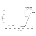
まず、測定対象物として樹体等の植物の緑葉を選択してその分光特性を観測すると、当該植物においては、図1に示すとおり、おおよそ690nmから750nmにかけての波長範囲において分光反射率が急峻に変化する波長領域がある(これを「レッドエッジ」という。)。
レッドエッジの波長領域は、一般に、植物が生育環境から受けるストレスによってシフトすることが知られている。その代表例として、レッドエッジの波長領域は、水分ストレス(樹体の渇き)が大きくなるにしたがい、短波長側にシフトするという特性を有している。したがって、植物の緑葉の分光特性を観測すれば、測定対象物のレッドエッジも算出することができ、その算出結果から植物の生育状態を把握(評価)することができる。
[First Embodiment]
First, when a green leaf of a plant such as a tree is selected as an object to be measured and the spectral characteristics thereof are observed, the spectral reflectance is steep in the wavelength range from approximately 690 nm to 750 nm as shown in FIG. There is a changing wavelength region (this is called “red edge”).
It is known that the wavelength region of the red edge is generally shifted by the stress that the plant receives from the growth environment. As a typical example, the wavelength region of the red edge has a characteristic of shifting to the short wavelength side as the water stress (tree thirst) increases. Therefore, by observing the spectral characteristics of the green leaves of the plant, the red edge of the measurement object can also be calculated, and the growth state of the plant can be grasped (evaluated) from the calculation result.
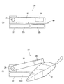
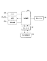
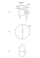
図2は、このような植物の分光特性を観測してその植物の生育状態を評価するための生育状態評価装置の概略構成を示す図面である。
図2(a)に示すとおり、生育状態評価装置20は概観上、主に固定部22、可動部24および軸部26から構成されている。
固定部22に対し可動部24が軸部26を介して回動可能となっている。
固定部22中には制御装置22aとバッテリ22bとが内蔵されている。
可動部24中にはセンサーヘッド28が内蔵されている。可動部24の表面には植物の生育状態を文字や図形などで表示するための表示パネル30(図5参照)が形成されている。
FIG. 2 is a drawing showing a schematic configuration of a growth state evaluation apparatus for observing the spectral characteristics of such a plant and evaluating the growth state of the plant.
As shown in FIG. 2A, the growth
A
The
A
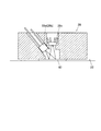
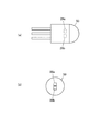
図3に示すとおり、センサーヘッド28はLED28a(28b)と光検出器28cとを有している。
センサーヘッド28は、LED28a(28b)が点灯して測定対象物40に向けて光を照射し、光検出器28cが測定対象物40で反射した光を受光(検出)するような構成を有している。
測定対象物40としては植物の緑葉が使用される。
As shown in FIG. 3, the
The
As the
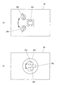
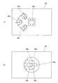
詳しくは、図4(a)に示すとおり、センサーヘッド28には、互いに発光波長が異なる2種のLED28a,28bと1台の光検出器28cとが設置されている。
2種のLED28a,28bは光源の一例であり、光検出器28cを中心とした円周上に配置され、その円周軌道上を移動可能となっている。
一方のLED28aの発光波長(λ1)は、レッドエッジの波長領域に対応する690〜750nmの範囲に存在し、本実施形態では730nmに設定されている。
他方のLED28bの発光波長(λ2)は、レッドエッジの波長領域よりも長波長の波長領域であって分光反射率に変化が少ないフラットな波長領域に対応する760nm以上の範囲に存在し、本実施形態では780nmに設定されている。
なお、測定対象物40として使用される緑葉の種類(レッドエッジの波長領域)に応じて、LED28a,28bの種類を変更し、その発光波長を適宜変更するようにしてもよい。
Specifically, as shown in FIG. 4A, the
The two types of
The light emission wavelength (λ1) of one
The emission wavelength (λ2) of the
Note that the type of the
図4(b)に示すとおり、センサーヘッド28の底面部には円形状の窓部28dが形成されている。LED28a,28bの光は窓部28dを通じて測定対象物40に照射され、その反射光は窓部28dを通じて光検出器28cで検出される。
生育状態評価装置20では、一方のLED28aが光照射してその反射光が光検出器28cで検出され、その後に他方のLED28bが一方のLED28aの位置に移動して再度光照射してその反射光が光検出器28cで検出される。
かかる場合、他方のLED28bが一方のLED28aの光照射位置まで移動するので、各LED28a,28bの照射光が光検出器28cに伝播する際の光路は同一となり、各伝播光路が一致するようになっている。
As shown in FIG. 4B, a
In the growth
In such a case, since the
続いて、生育状態評価装置20の制御構成について説明する。
Then, the control structure of the growth
図5に示すとおり、制御装置22aにはバッテリ22bやLED28a,28b、光検出器28c、表示パネル30などが接続されている。
特に、生育状態評価装置20では、制御装置22aが2種のLED28a,28bを発光させて光検出器28cによる検出結果を受け、その検出結果から植物の生育状態を指標値により算出するようになっている(指標値の算出方法などは後述する。)。
生育状態評価装置20では、制御装置22aはインターフェース32を介して外部処理装置34との通信が可能とされてもよい。かかる場合、通信は有線によるものとしてもよいし、無線によるものとしてもよい。
As shown in FIG. 5, a
In particular, in the growth
In the growth
続いて、生育状態評価装置20を用いた植物の生育状態の評価方法について説明する。
Then, the evaluation method of the growth state of the plant using the growth
生育状態評価装置20はいわゆる反射型の分光測定装置であり、バッテリ22bを内蔵するため携帯性を有している。
実際に、生育状態評価装置20を使用して植物の生育状態を評価する場合は、作業者が生育状態評価装置20を携帯して植物のある栽培地に出向き、図4(b)に示すとおり、測定対象物40(緑葉)を固定部22と可動部24との間に挟持し生育状態評価装置20を作動させる。
かかる場合、好ましくは、緑葉の葉脈の影響やそり具合、葉の場所による分光特性の違いの影響が最小となるように、極力中央でかつ平坦な部分を挟み込むようにする。また、同一植物の経時特性を見る際は、極力同一の緑葉の同一の箇所を観測するようにする。
The growth
When actually evaluating the growth state of a plant using the growth
In such a case, it is preferable to sandwich a flat portion at the center as much as possible so that the influence of the leaf veins of the green leaves, the state of warpage, and the difference in spectral characteristics depending on the location of the leaves are minimized. When looking at the time-dependent characteristics of the same plant, the same part of the same green leaf should be observed as much as possible.
生育状態評価装置20が作動すると、制御装置22aが、バッテリ22bの電力の供給を受けながら、一方のLED28aを点灯させ、測定対象物40に発光波長λ1の光を照射するとともに、光検出器28cにその反射光を検出させる。
その後、制御装置22aは、他方のLED28bを制御して一方のLED28aの点灯位置まで移動させ、その位置でLED28bを点灯させて測定対象物40に発光波長λ2の光を照射し、上記と同様に、光検出器28cにその反射光を検出させる。
かかる場合、制御装置22aは、発光波長λ1,λ2の光を、異なる周波数で変調し、その反射光を光検出器28cに検出させる。
検出された反射光(光量)は順次、光検出器28cから制御装置22aに送信され、制御装置22aは光検出器28cの検出結果を受信する。
When the growth
Thereafter, the
In such a case, the
The detected reflected light (light quantity) is sequentially transmitted from the
その後、制御装置22aは、光検出器28cの検出結果から、LED28a,28bの変調周波数に対応した強度出力値(Iλ1,Iλ2)を算出する。
なお、LED28a,28bを発光させていないときの光検出器28cから出力される暗電流や外乱光成分をバックグラウンド出力としてあらかじめ求めておき、測定対象物40の分光測定時の出力から差し引くことにより、測定精度を向上させてもよい。
その後、制御装置22aは、演算プログラムにしたがってこの出力値(Iλ1,Iλ2)を処理し、Iλ1/Iλ2または(Iλ1−Iλ2)/(Iλ1+Iλ2)の値を、植物の生育状態を評価するための指標値として、算出する。
Iλ1/Iλ2による演算は最も単純なものであり、レッドエッジの中心波長に対応する指標値となる。(Iλ1−Iλ2)/(Iλ1+Iλ2)はレッドエッジの傾斜に対応する指標値となる。
その後、制御装置22aは、算出した指標値やその指標値と一定の基準値との差などを、表示パネル30に表示したり外部処理装置34に出力したりする。
Thereafter, the
The dark current and disturbance light components output from the
Thereafter, the
The calculation by Iλ1 / Iλ2 is the simplest and becomes an index value corresponding to the center wavelength of the red edge. (Iλ1−Iλ2) / (Iλ1 + Iλ2) is an index value corresponding to the inclination of the red edge.
Thereafter, the
以上の本実施形態によれば、一方のLED28aが点灯した後に他方のLED28bがその点灯位置に移動し点灯するから、各LED28a,28bの照射光の伝播経路が一致する。そのため、測定対象物40に光照射してこれを検出する際に、緑葉の葉脈の状態や緑葉自体のそり具合などによる影響が軽減され、測定誤差の発生を抑制することができ、ひいては植物の生育状態の評価精度を向上させることができる。
According to the present embodiment described above, after one
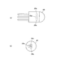
[変形例1]
図6に示すとおり、2種のLED28a,28bを近接した位置に配置した状態で同一のパッケージ50内に実装しこれを光源として使用してもよい。
かかる場合、LED28a,28bの各照射光の伝播光路は完全には一致しないが、本実施形態のように、LED28a,28bの配置が同じパッケージ内に収まる程度に近接していれば、各照射光の伝播光路は一致するものとみなしてよい。
[Modification 1]
As shown in FIG. 6, two types of
In such a case, the propagation optical paths of the irradiation lights of the
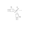
[変形例2]
図7に示すとおり、LED28a,28bの位置を固定するとともに各照射光の伝播光路上に合波ミラー52を配置し、各照射光の伝播光路を一致させてもよい。
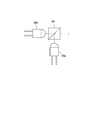
[変形例3]
図8に示すとおり、LED28a,28bの位置を固定するとともに各照射光の伝播光路上に合波プリズム54を配置し、各照射光の伝播光路を一致させてもよい。
[変形例4]
図9(a),(b)に示すとおり、LED28a(またはLED28b)のみを単一使用してこれを固定するとともに、その照射光の伝播光路上に2波長分の波長変換がおこなえる円形状のバンドパスフィルター56を配置し、バンドパスフィルター56をモータ58で回転させるようにしてもよい。
かかる場合、照射光は、発光波長自体が同じでも伝播波長を変更することができ、その伝播光路を一致させることができる。
図9(c)に示すとおり、バンドパスフィルター56として矩形状のものを使用し、これを1方向に往復移動させるようにしてもよい。
[Modification 2]
As shown in FIG. 7, the positions of the
[Modification 3]
As shown in FIG. 8, the positions of the
[Modification 4]
As shown in FIGS. 9 (a) and 9 (b), a
In such a case, the irradiation light can change the propagation wavelength even if the emission wavelength itself is the same, and the propagation optical path can be matched.
As shown in FIG. 9C, a rectangular filter may be used as the
[第2の実施形態]
第2の実施形態は下記の点で第1の実施形態と異なっており、それ以外の構成や作用等の技術的事項は第1の実施形態と同様となっている。
[Second Embodiment]
The second embodiment is different from the first embodiment in the following points, and other technical matters such as configuration and operation are the same as those of the first embodiment.
図10に示すとおり、植物生育評価装置20では、センサーヘッド28において、2種のLED28a,28bに加え第3のLED28eが設けられている。
本実施形態でも、LED28a,28b,28eは光検出器28cを中心とした円周上に配置され、その円周軌道上を移動可能となっている。
第3のLED28eの発光波長(λ3)は、レッドエッジの波長領域に対応する690〜750nmの範囲に存在している。
本実施形態では、LED28aの発光波長λ1は720nmに設定され、LED28eの発光波長λ3は740nmに設定されている(LED28bの発光波長λ2は780nmに設定されたままである。)。
As shown in FIG. 10, in the plant
Also in this embodiment, the
The emission wavelength (λ3) of the
In the present embodiment, the light emission wavelength λ1 of the
本実施形態でも、生育状態評価装置20を用いた植物の生育状態の評価方法についての操作や動作は、第1の実施形態と同様である。
異なるのは、レッドエッジの波長領域に対してLED28a,28cの発光波長λ1,λ3の2波長分を割り当てたことであり、その結果として、レッドエッジの波長領域の傾斜を、指標値として表示ならびに出力できる点にある。
指標値を算出する場合は、制御装置22aによって、光検出器28cの検出結果を、LED28a,28b,28eの変調周波数に対応した強度出力値(Iλ1,Iλ2,Iλ3)を算出し、(Iλ1−Iλ3)/(Iλ1+Iλ3)の値を指標値として算出する。
かかる場合、Iλ2は、光束の測定対象物40への当たり方で反射率に誤差が生じたときに、光検出器28cに入射する光量が変化するのを補正するのに使用される。
さらに、指標値を算出する場合、(Iλ1+Iλ3)/2×Iλ2の値を算出してこれを指標値としてもよい。
Also in this embodiment, the operation and operation of the plant growth state evaluation method using the growth
The difference is that two wavelengths of the emission wavelengths λ1 and λ3 of the
When calculating the index value, the
In this case, Iλ2 is used to correct a change in the amount of light incident on the
Further, when calculating the index value, a value of (Iλ1 + Iλ3) / 2 × Iλ2 may be calculated and used as the index value.
以上の本実施形態によれば、レッドエッジの波長領域に対してLED28a,28cの発光波長λ1,λ3の2波長分を割り当てているから、第1の実施形態よりさらに多様な指標値の出力が可能となる。
According to the above-described embodiment, since the two wavelengths of the emission wavelengths λ1 and λ3 of the
[変形例1]
図11に示すとおり、3種のLED28a,28b,28eを近接した位置に配置した状態で同一のパッケージ60内に実装しこれを光源として使用してもよい。
かかる場合、LED28a,28b,28eの各照射光の伝播光路は完全には一致しないが、本実施形態のように、LED28a,28b,28eの配置が同じパッケージ内に収まる程度に近接していれば、各照射光の伝播光路は一致するものとみなしてよい。
[Modification 1]
As shown in FIG. 11, three types of
In such a case, the propagation light paths of the irradiation lights of the
[変形例2]
図12(a),(b)に示すとおり、LED28a(またはLED28b,28e)のみを単一使用してこれを固定するとともに、その照射光の伝播光路上に3波長分の波長変換がおこなえる円形状のバンドパスフィルター62を配置し、バンドパスフィルター62をモータ64で回転させるようにしてもよい。
かかる場合、照射光は、発光波長自体が同じでも伝播波長を変更することができ、その伝播光路を一致させることができる。
図12(c)に示すとおり、バンドパスフィルター62として矩形状のものを使用してこれを1方向に往復移動させるようにしてもよい。
[Modification 2]
As shown in FIGS. 12 (a) and 12 (b), only a
In such a case, the irradiation light can change the propagation wavelength even if the emission wavelength itself is the same, and the propagation optical path can be matched.
As shown in FIG. 12C, a rectangular filter may be used as the
なお、LED28a,28b,28cを移動させる構成(図4および図10参照)、LED28a,28b,28cを同一パッケージに実装する構成(図6および図11参照)、合波ミラー52や合波プリズム54を使用する構成(図7および図8)およびバンドパスフィルター56,62を使用する構成(図9および図12参照)のいずれにおいても、照射光の伝播光路を一致させる範囲内で、光源の数は適宜変更可能である。
In addition, the structure which moves LED28a, 28b, 28c (refer FIG. 4 and FIG. 10), the structure which mounts LED28a, 28b, 28c in the same package (refer FIG. 6 and FIG. 11), the combining
20 生育状態評価装置
22 固定部
22a 制御装置
22b バッテリ
24 可動部
26 軸部
28 センサーヘッド
28a,28b LED
28c 光検出器
28d 窓部
28e LED
30 表示パネル
32 インターフェース
34 外部処理装置
40 測定対象物
DESCRIPTION OF
30
Claims (5)
発光波長(λ1)が前記測定対象物の分光反射率のレッドエッジの波長領域に存在する第1の光源と、発光波長(λ2)が前記レッドエッジの波長領域よりも長波長のフラットな波長領域に存在する第2の光源と、前記第1の光源と前記第2の光源との各照射光を検出する光検出器とを備え、
前記第1の光源の照射光の伝播光路と前記第2の光源の伝播光路とが一致することを特徴とする生育状態評価装置。 A growth state evaluation apparatus that irradiates a measurement object with a plurality of lights having different emission wavelengths and detects the reflected light to evaluate the growth state of a plant,
A first light source in which the emission wavelength (λ1) is present in the wavelength region of the red edge of the spectral reflectance of the measurement object, and a flat wavelength region in which the emission wavelength (λ2) is longer than the wavelength region of the red edge A second light source present in the light source, and a photodetector for detecting each irradiation light of the first light source and the second light source,
A growth state evaluation apparatus, wherein a propagation light path of irradiation light of the first light source and a propagation light path of the second light source coincide with each other.
前記第1の光源、前記第2の光源および前記光検出器を制御する制御装置であって、前記光検出器の検出結果から、前記第1の光源の発光波長に対応する光の出力値(Iλ1)と、前記第2の光源の発光波長に対応する光の出力値(Iλ2)とを算出し、Iλ1/Iλ2または(Iλ1−Iλ2)/(Iλ1+Iλ2)の値を、前記測定対象物の生育状態を評価する際の指標値として、算出する前記制御装置を備えることを特徴とする生育状態評価装置。 In the growth condition evaluation apparatus according to claim 1,
A control device that controls the first light source, the second light source, and the photodetector, wherein a light output value (corresponding to an emission wavelength of the first light source) is detected from a detection result of the photodetector. Iλ1) and a light output value (Iλ2) corresponding to the emission wavelength of the second light source are calculated, and the value of Iλ1 / Iλ2 or (Iλ1-Iλ2) / (Iλ1 + Iλ2) is calculated as the growth of the measurement object. A growth state evaluation apparatus comprising the control device for calculating an index value for evaluating a state.
発光波長(λ3)が前記測定対象物の分光反射率のレッドエッジの波長領域に存在し、かつ、前記第1の光源の発光波長と異なる第3の光源を備え、
前記制御装置が、前記光検出器の検出結果から、記第1の光源の発光波長に対応する光の出力値(Iλ1)と、前記第2の光源の発光波長に対応する光の出力値(Iλ2)と、前記第3の光源の発光波長に対応する光の出力値(Iλ3)とを算出し、(Iλ1−Iλ3)/(Iλ1+Iλ3)をIλ2で補正した値または(Iλ1+Iλ3)/2×Iλ2の値を、前記測定対象物の生育状態を評価する際の指標値として、算出することを特徴とする生育状態評価装置。 In the growth condition evaluation apparatus according to claim 1,
A light emission wavelength (λ3) is present in the wavelength region of the red edge of the spectral reflectance of the measurement object, and includes a third light source different from the light emission wavelength of the first light source,
From the detection result of the photodetector, the control device outputs the light output value (Iλ1) corresponding to the emission wavelength of the first light source and the light output value (Iλ1) corresponding to the emission wavelength of the second light source ( Iλ2) and a light output value (Iλ3) corresponding to the emission wavelength of the third light source are calculated, and (Iλ1−Iλ3) / (Iλ1 + Iλ3) is corrected by Iλ2, or (Iλ1 + Iλ3) / 2 × Iλ2 The growth state evaluation apparatus is characterized in that the value is calculated as an index value for evaluating the growth state of the measurement object.
前記レッドエッジの波長領域が690〜750nmであり、
前記フラットな波長領域が760nm以上であることを特徴とする生育状態評価装置。 In the growth condition evaluation apparatus according to any one of claims 1 to 3,
The wavelength region of the red edge is 690 to 750 nm,
The growth state evaluation apparatus, wherein the flat wavelength region is 760 nm or more.
前記第1の光源、前記第2の光源および前記第3の光源はLEDであり、
これら光源が同一のパッケージ内に実装されていることを特徴とする生育状態評価装置。 In the growth condition evaluation apparatus according to claims 1 to 4,
The first light source, the second light source, and the third light source are LEDs,
A growth state evaluation apparatus in which these light sources are mounted in the same package.
Priority Applications (1)
| Application Number | Priority Date | Filing Date | Title |
|---|---|---|---|
| JP2011136833A JP2013000090A (en) | 2011-06-21 | 2011-06-21 | Growth state evaluating device |
Applications Claiming Priority (1)
| Application Number | Priority Date | Filing Date | Title |
|---|---|---|---|
| JP2011136833A JP2013000090A (en) | 2011-06-21 | 2011-06-21 | Growth state evaluating device |
Publications (1)
| Publication Number | Publication Date |
|---|---|
| JP2013000090A true JP2013000090A (en) | 2013-01-07 |
Family
ID=47669349
Family Applications (1)
| Application Number | Title | Priority Date | Filing Date |
|---|---|---|---|
| JP2011136833A Pending JP2013000090A (en) | 2011-06-21 | 2011-06-21 | Growth state evaluating device |
Country Status (1)
| Country | Link |
|---|---|
| JP (1) | JP2013000090A (en) |
Cited By (5)
| Publication number | Priority date | Publication date | Assignee | Title |
|---|---|---|---|---|
| JP5982731B1 (en) * | 2016-02-26 | 2016-08-31 | パナソニックIpマネジメント株式会社 | Water content observation device, water content observation method and cultivation device |
| WO2016194507A1 (en) * | 2015-06-02 | 2016-12-08 | 株式会社トプコン | Wavelength sensor device for plant |
| JP2019109104A (en) * | 2017-12-18 | 2019-07-04 | 株式会社オーガニックnico | Living body holding structure used for growth condition measuring device of crop under cultivation |
| JP2020154854A (en) * | 2019-03-20 | 2020-09-24 | 株式会社ニコン | Inspection equipment, evaluation equipment and programs |
| KR20200139920A (en) * | 2019-06-05 | 2020-12-15 | 주식회사 마하테크 | apparatus for monitoring growth state of farm product |
Citations (4)
| Publication number | Priority date | Publication date | Assignee | Title |
|---|---|---|---|---|
| JPH11149262A (en) * | 1997-11-17 | 1999-06-02 | Copal Co Ltd | White light emitting element and lightning display unit |
| JPH11163414A (en) * | 1997-11-26 | 1999-06-18 | Rohm Co Ltd | Light emitting device |
| JP2005308733A (en) * | 2004-03-25 | 2005-11-04 | Nagasaki Prefecture | Method and instrument for measuring stress imparted to plant |
| JP2010054436A (en) * | 2008-08-29 | 2010-03-11 | Topcon Corp | Plant sensor |
-
2011
- 2011-06-21 JP JP2011136833A patent/JP2013000090A/en active Pending
Patent Citations (4)
| Publication number | Priority date | Publication date | Assignee | Title |
|---|---|---|---|---|
| JPH11149262A (en) * | 1997-11-17 | 1999-06-02 | Copal Co Ltd | White light emitting element and lightning display unit |
| JPH11163414A (en) * | 1997-11-26 | 1999-06-18 | Rohm Co Ltd | Light emitting device |
| JP2005308733A (en) * | 2004-03-25 | 2005-11-04 | Nagasaki Prefecture | Method and instrument for measuring stress imparted to plant |
| JP2010054436A (en) * | 2008-08-29 | 2010-03-11 | Topcon Corp | Plant sensor |
Cited By (8)
| Publication number | Priority date | Publication date | Assignee | Title |
|---|---|---|---|---|
| WO2016194507A1 (en) * | 2015-06-02 | 2016-12-08 | 株式会社トプコン | Wavelength sensor device for plant |
| JP2016223971A (en) * | 2015-06-02 | 2016-12-28 | 株式会社トプコン | Wavelength sensor device for plant |
| JP5982731B1 (en) * | 2016-02-26 | 2016-08-31 | パナソニックIpマネジメント株式会社 | Water content observation device, water content observation method and cultivation device |
| WO2017145980A1 (en) * | 2016-02-26 | 2017-08-31 | パナソニックIpマネジメント株式会社 | Moisture content observation device, moisture content observation method, and cultivating device |
| JP2019109104A (en) * | 2017-12-18 | 2019-07-04 | 株式会社オーガニックnico | Living body holding structure used for growth condition measuring device of crop under cultivation |
| JP2020154854A (en) * | 2019-03-20 | 2020-09-24 | 株式会社ニコン | Inspection equipment, evaluation equipment and programs |
| KR20200139920A (en) * | 2019-06-05 | 2020-12-15 | 주식회사 마하테크 | apparatus for monitoring growth state of farm product |
| KR102197321B1 (en) * | 2019-06-05 | 2020-12-31 | 주식회사 마하테크 | apparatus for monitoring growth state of farm product |
Similar Documents
| Publication | Publication Date | Title |
|---|---|---|
| JP6075372B2 (en) | Material property measuring device | |
| JP2013096883A5 (en) | ||
| US11585758B2 (en) | Microspectroscopic device and microspectroscopic method | |
| EP3133380B1 (en) | Photodetector output correction method used for spectroscopic analyzer or spectroscope, spectroscopic analyzer or spectroscope using this method and program for spectroscopic analyzer or spectroscope instructing this method | |
| JP2015526135A5 (en) | ||
| JP2013000090A (en) | Growth state evaluating device | |
| CN105928688B (en) | The measuring device and method of diffraction efficiency of grating spectrum based on single exposure pattern | |
| JP6027317B2 (en) | System and method for wavelength spectrum analysis for detecting various gases using processed tape | |
| JP5023507B2 (en) | Wavelength calibration method and wavelength calibration apparatus | |
| JP2009122083A (en) | Meter using near-infrared led | |
| JPWO2017029791A1 (en) | Concentration measuring device | |
| JP2017026506A5 (en) | ||
| KR102477678B1 (en) | NDIR glucose detection in liquids | |
| JP2009109363A (en) | Method and device for measuring water stress of plant | |
| JP2022543147A (en) | METHOD AND APPARATUS FOR MEASURING GAS SPEED QUANTITY USING OPTICAL SENSOR | |
| CN201277944Y (en) | Integrating sphere detection system | |
| WO2012053877A4 (en) | Method and device for diagnosing plant growing conditions | |
| JP6230017B2 (en) | Component concentration analyzer using light emitting diode | |
| JP3903147B2 (en) | Non-destructive sugar content measuring device for fruits and vegetables | |
| US8873040B2 (en) | Raman apparatus and method for real time calibration thereof | |
| JP2012132745A5 (en) | ||
| JP2014142299A (en) | Gas concentration measurement device | |
| JP5576084B2 (en) | Outdoor crop internal quality measuring device | |
| CA3130795C (en) | Spectrometer system and method for testing of same | |
| JP2013183702A (en) | Method for diagnosing growing state of plant and device used for the same |
Legal Events
| Date | Code | Title | Description |
|---|---|---|---|
| A711 | Notification of change in applicant |
Free format text: JAPANESE INTERMEDIATE CODE: A712 Effective date: 20130416 |
|
| A621 | Written request for application examination |
Free format text: JAPANESE INTERMEDIATE CODE: A621 Effective date: 20131210 |
|
| A977 | Report on retrieval |
Free format text: JAPANESE INTERMEDIATE CODE: A971007 Effective date: 20140724 |
|
| A131 | Notification of reasons for refusal |
Free format text: JAPANESE INTERMEDIATE CODE: A131 Effective date: 20140826 |
|
| A02 | Decision of refusal |
Free format text: JAPANESE INTERMEDIATE CODE: A02 Effective date: 20150106 |