JP2012532999A - Equipment for screening fiber suspensions - Google Patents
Equipment for screening fiber suspensions Download PDFInfo
- Publication number
- JP2012532999A JP2012532999A JP2012519028A JP2012519028A JP2012532999A JP 2012532999 A JP2012532999 A JP 2012532999A JP 2012519028 A JP2012519028 A JP 2012519028A JP 2012519028 A JP2012519028 A JP 2012519028A JP 2012532999 A JP2012532999 A JP 2012532999A
- Authority
- JP
- Japan
- Prior art keywords
- slot
- screening
- drum
- slots
- row
- Prior art date
- Legal status (The legal status is an assumption and is not a legal conclusion. Google has not performed a legal analysis and makes no representation as to the accuracy of the status listed.)
- Abandoned
Links
Images


Classifications
-
- D—TEXTILES; PAPER
- D21—PAPER-MAKING; PRODUCTION OF CELLULOSE
- D21D—TREATMENT OF THE MATERIALS BEFORE PASSING TO THE PAPER-MAKING MACHINE
- D21D5/00—Purification of the pulp suspension by mechanical means; Apparatus therefor
- D21D5/02—Straining or screening the pulp
- D21D5/06—Rotary screen-drums
-
- D—TEXTILES; PAPER
- D21—PAPER-MAKING; PRODUCTION OF CELLULOSE
- D21D—TREATMENT OF THE MATERIALS BEFORE PASSING TO THE PAPER-MAKING MACHINE
- D21D5/00—Purification of the pulp suspension by mechanical means; Apparatus therefor
- D21D5/02—Straining or screening the pulp
- D21D5/16—Cylinders and plates for screens
Landscapes
- Engineering & Computer Science (AREA)
- Mechanical Engineering (AREA)
- Paper (AREA)
- Combined Means For Separation Of Solids (AREA)
Abstract
本発明は、繊維懸濁液用のスクリーン、特に粗粒子を除去するスクリーンに関する。スクリーンは、ケーシングと、ケーシングに連結され、繊維懸濁液を装置に供給し、リジェクト及びアクセプトを排出する導管と、ハウジングの内側に配置され、鉛直方向軸線の周りで回転するドラムとを備え、ドラムのスクリーニング表面には、アクセプト部分が流れる開口が設けられている。供給導管及び出口導管は、繊維懸濁液がケーシングとスクリーン・ドラムとの間にある空間に供給され、アクセプトがスクリーン・ドラムの内部から排出されるように配置されている。スクリーニング表面にある開口はスロットであり、スロットのドラムの回転方向に対する長手方向の向きは−40度〜+40度であり、長さ対幅の比は1.05〜10である。スロットは、スロット列を形成し、スクリーニング表面の外面は、スロット列間に隆起が設けられるように形成される。 The present invention relates to a screen for fiber suspension, in particular a screen for removing coarse particles. The screen comprises a casing, a conduit connected to the casing, supplying a fiber suspension to the apparatus, discharging rejects and accepts, and a drum disposed inside the housing and rotating about a vertical axis; The screening surface of the drum is provided with an opening through which the accepting portion flows. The supply conduit and the outlet conduit are arranged so that the fiber suspension is supplied to the space between the casing and the screen drum and the accept is discharged from the interior of the screen drum. The opening in the screening surface is a slot, the longitudinal orientation of the slot with respect to the direction of drum rotation is -40 degrees to +40 degrees, and the length to width ratio is 1.05 to 10. The slots form slot rows and the outer surface of the screening surface is formed such that ridges are provided between the slot rows.
Description
本発明は、化学パルプ及び製紙産業において繊維及び類似物をスクリーニングする装置、とりわけノット(節)、石、及び他の固体粒子等の粗粒子を繊維懸濁液から分離する粗選スクリーニング用の装置に関するものである。本発明は、回転スクリーン・ドラムを有する装置に係るものである。 The present invention relates to an apparatus for screening fibers and the like in the chemical pulp and paper industry, in particular for a coarse screening that separates coarse particles such as knots, stones and other solid particles from fiber suspensions. It is about. The present invention relates to an apparatus having a rotating screen drum.
木材パルプ選別機の処理では、スクリーンを用いて、懸濁液中の許容される繊維を望ましくない物質から分離する。通常のスクリーン構造は、繊維懸濁液用の供給導管を有する。繊維懸濁液は、木材チップの蒸解によって、又は二次パルプ繊維を得る解繊機で生成されたものでよい。懸濁液には、ノット、スライバ(篠)、樹皮粒子、土砂、金属粒子、及び他の望ましくない物質が含まれ得る。 In wood pulp sorter processing, screens are used to separate the acceptable fibers in the suspension from undesirable materials. A typical screen structure has a supply conduit for the fiber suspension. The fiber suspension may be produced by cooking wood chips or with a defibrator that obtains secondary pulp fibers. The suspension may include knots, sliver, bark particles, earth and sand, metal particles, and other undesirable materials.
ケーシングのスクリーン内側では、繊維懸濁液が、プレート又はバスケットとしばしば呼ばれる円筒形スクリーン付近を流れ、許容される繊維片、すなわちアクセプト(accept)がそのスクリーン・プレートを通過し、一方リジェクト(reject)は、スクリーン・プレートの第1の側に留まり、ケーシングのリジェクト開口から排出される。円筒形状のスクリーン・プレート、すなわちスクリーン・ドラムが回転すると、繊維懸濁液が、スクリーン・プレートの表面を通過する繊維懸濁液の流れを強めるための衝撃要素又は乱流要素を通り越し、したがってスクリーニングも促進される。スクリーン・プレートは、スクリーニング工程に適した寸法を有する孔又はスロットの開口を有する。スクリーン・プレート開口の寸法は、許容された繊維がスクリーニング表面を通過し、望ましくない物質の通過が阻止されるように適したものでなければならない。 Inside the screen of the casing, the fiber suspension flows around a cylindrical screen, often referred to as a plate or basket, and acceptable fiber pieces, or accepts, pass through the screen plate, while rejecting. Remains on the first side of the screen plate and is discharged from the reject opening in the casing. As the cylindrical screen plate, or screen drum, rotates, the fiber suspension passes through the impact or turbulence elements to enhance the flow of the fiber suspension through the surface of the screen plate, and thus screening. Is also promoted. The screen plate has a hole or slot opening with dimensions suitable for the screening process. The size of the screen plate opening must be suitable so that the accepted fibers pass through the screening surface and prevent the passage of unwanted material.
欧州特許出願公開第275967号(FI76139)には、ノットを分離する方法及び装置が示されている。ここでは概ね低いレベルのMC濃度(6〜8%)が実現されている。使用可能な濃度範囲の拡大は、スクリーニング表面の外形を適切に寸法設定及び設計し、且つスクリーン・ドラムの回転速度とパルプの供給速度とを最適化することによって実現される。この公開公報に記載の装置では、ドラムの回転方向は、パルプの供給方向と同じであり、リジェクト排出方向もドラムの回転方向と同じである。更に、このスクリーン・ドラムは、ドラム外面のスクリーン開口間に隆起が設けられるように外形が形成され、これらの隆起は、ドラム外面から傾斜位置に立ち上がる前面と、外面に実質的に垂直な後面とを備える。隆起のドラム軸線に対する傾斜角度は、−45〜+45度である。ドラムにある開口は、孔又はスロットでよいが、通常は、この種のスクリーンのスクリーニング表面には丸孔が設けられ、その直径は、用途の目的に応じて5〜15mmの範囲で変動できる。 EP-A-275967 (FI 76139) shows a method and apparatus for separating knots. Here, a generally low level of MC concentration (6-8%) is realized. Expansion of the usable concentration range is achieved by appropriately sizing and designing the contour of the screening surface and optimizing the screen drum rotation speed and pulp feed rate. In the device described in this publication, the rotation direction of the drum is the same as the pulp supply direction, and the reject discharge direction is the same as the rotation direction of the drum. Further, the screen drum is contoured so that ridges are provided between the screen openings on the drum outer surface, the ridges having a front surface rising from the drum outer surface to an inclined position, and a rear surface substantially perpendicular to the outer surface. Is provided. The inclination angle of the bulge with respect to the drum axis is −45 to +45 degrees. The opening in the drum may be a hole or a slot, but usually the screening surface of this type of screen is provided with a round hole whose diameter can vary between 5 and 15 mm depending on the purpose of the application.
欧州特許第EP1357222号(米国出願公開第2004004032号)には、固定スクリーン・ドラムを有する、繊維懸濁液用の精選スクリーンが記載され、このドラム内側では、ブレード部材が回転して、スクリーニング表面を清浄にしている。このスクリーニング表面には、幅1〜8mm、長さ対幅の比が2〜20の細長い開口が設けられている。この発明の目的は、アクセプト中の長繊維の比率を増大させることである。米国特許第490417号にも、固定スクリーン・ドラムを有するスクリーンが示されている。スクリーニング表面にあるスロットは互いに平行であるが、ドラム軸線に対して傾斜させることができる。 EP 1357222 (U.S. Published Application 2004004032) describes a screening screen for fiber suspensions having a fixed screen drum, inside which a blade member is rotated to move the screening surface. It is clean. The screening surface is provided with elongated openings having a width of 1-8 mm and a length to width ratio of 2-20. The object of this invention is to increase the proportion of long fibers in the accept. U.S. Pat. No. 4,904,417 also shows a screen with a fixed screen drum. The slots in the screening surface are parallel to each other but can be tilted with respect to the drum axis.
本発明の目的は、従来よりもエネルギー効率の良い形で、高濃度(6%超までにも)に達することができる、粗選スクリーン用の回転スクリーン・ドラムを提供することである。 The object of the present invention is to provide a rotating screen drum for a coarse screen which can reach high concentrations (up to more than 6%) in a more energy efficient manner than before.
本発明は、繊維懸濁液をスクリーニングする装置、とりわけノット等の粗粒子を除去する粗選スクリーニング用の装置に係るものである。この装置は、ケーシングと、繊維懸濁液用の供給導管並びにリジェクト用及びアクセプト用の出口導管と、ケーシング内で鉛直方向のシャフト(7)の周りで回転できるように配置され、アクセプト部分が流れる開口(21)が設けられたスクリーニング表面(20)を有するスクリーン・ドラム(5)とを備える。この装置の供給導管及び出口導管は、繊維懸濁液がケーシングとスクリーン・ドラムとの間にある空間に供給され、アクセプト部分がスクリーン・ドラムの内側から排出されるように配置される。本発明によれば、スクリーニング表面にある開口はスロットであり、これらのスロットでは、ドラムの回転方向に対する長手方向の向きは−40度〜+40度であり、スロットの長さ対幅の比は1.05〜10であり、このスロットはスロット列を形成し、スクリーニング表面の外面が、スロット列同士の間に隆起が設けられるよう外形が形成される。 The present invention relates to an apparatus for screening a fiber suspension, and more particularly to an apparatus for coarse screening that removes coarse particles such as knots. The device is arranged to rotate around a vertical shaft (7) in the casing, a supply conduit for the fiber suspension and an outlet conduit for rejecting and accepting, and a vertical shaft (7) in the casing, the accepting part flowing. A screen drum (5) having a screening surface (20) provided with an opening (21). The supply and outlet conduits of this device are arranged so that the fiber suspension is fed into the space between the casing and the screen drum and the accepting portion is discharged from the inside of the screen drum. According to the present invention, the openings in the screening surface are slots, in which the longitudinal orientation with respect to the direction of drum rotation is -40 degrees to +40 degrees, and the ratio of slot length to width is 1. .05 to 10 and this slot forms a slot row, and the outer surface of the screening surface is shaped so that a ridge is provided between the slot rows.
好ましい実施例によれば、開口の長手方向の向き/長手方向軸線は、ドラムの回転方向に対して−30〜+30度、好ましくは−15〜+15度である。好ましい実施例によれば、開口の長手方向が延びる向きは、実質的にドラムの回転方向と同じであり、すなわちスクリーン・ドラムの長手方向軸線に垂直である。 According to a preferred embodiment, the longitudinal direction / longitudinal axis of the opening is −30 to +30 degrees, preferably −15 to +15 degrees with respect to the direction of rotation of the drum. According to a preferred embodiment, the direction in which the longitudinal direction of the opening extends is substantially the same as the direction of rotation of the drum, i.e. perpendicular to the longitudinal axis of the screen drum.
スロットは、長方形又は楕円形である。スロット端部の縁は、角形又は丸形である。通常、スロットは細長い。幅は、通常は4〜12mmである。スロットの長さ対幅の比は1.05〜10、好ましくは2〜8である。 The slot is rectangular or elliptical. The edge of the slot end is square or round. Usually, the slot is elongated. The width is usually 4 to 12 mm. The ratio of slot length to width is 1.05 to 10, preferably 2 to 8.
スロットは、ドラムの軸線方向に上下に並んで配置され、それによってスロット列/スロット領域が形成され、これらのスロット列/スロット領域は、ドラムの円周方向に互いに間隔を置いて配置される。通常は、鉛直方向のスロット列は傾斜して配置される。 The slots are arranged side by side in the axial direction of the drum, thereby forming a slot row / slot region, and these slot rows / slot regions are spaced apart from each other in the circumferential direction of the drum. Normally, the vertical slot rows are inclined.
好ましい実施例によれば、ドラムのスクリーニング表面の外面は、スロット列/スロット領域同士の間に隆起が配置されるように形成される。外面とは、繊維懸濁液が供給され、アクセプト部分が開口を通過して他方側の面に流れ、リジェクト部分がそこに留まるドラム側面を指す。好ましくは隆起は、ドラムの鉛直方向軸線に対して角度−5〜+20度、通常は15度となるように配置される。ドラム鉛直方向軸線に対する鉛直方向スロット列の線は、スロットの端部が隆起に対して実質的に平行な線を形成するように、すなわち、通常はドラム鉛直方向軸線に対して傾斜した位置となるように変化させることができる。 According to a preferred embodiment, the outer surface of the drum screening surface is formed such that ridges are arranged between the slot rows / slot regions. The outer surface refers to the side of the drum where the fiber suspension is supplied, the accepting portion flows through the opening to the other surface and the rejecting portion remains there. Preferably, the ridges are arranged at an angle of -5 to +20 degrees, usually 15 degrees with respect to the vertical axis of the drum. The line in the vertical slot row relative to the drum vertical axis is such that the end of the slot forms a line that is substantially parallel to the ridge, i.e., typically inclined relative to the drum vertical axis. Can be changed.
この外形は、スクリーン表面の平面に対してある角度をなす前面及び後面と、場合によっては前面と後面との間のプレート平面に実質的に平行な表面とを有する隆起により形成される。隆起の傾斜角度、回転方向に対する傾斜の向き、ドラムの回転速度、及び隆起前面の立ち上がり角度によって、最終的に得られる分離(アクセプト/リジェクト)に応じてパルプ循環時間及び乱流を最適化することが可能となる。流れを受ける隆起の前面が後方に傾斜し、すなわち前面がスクリーニング表面の平面から立ち上がり、後面が垂直である場合、スクリーニング表面にある開口を均等に通過して流れる流動が得られる。この流動によって、ある状況下で生じることのある懸濁液の流れが逆方向に乱れることがなくなる。一具体例によれば、隆起の前面は、スクリーン表面の平面に垂直でもよく、したがって後面が下がっていてもよい。その場合、前面は流れに逆らい、流れを混ぜ、それによってスクリーニング表面を通過する流れが増大し、したがって装置の生産能力が増大するが、それと同時に分離能力は低減する。隆起の前面及び後面は、対称的に傾斜させることもできる。 This profile is formed by ridges having front and rear surfaces that are at an angle to the plane of the screen surface and possibly surfaces that are substantially parallel to the plate plane between the front and rear surfaces. Optimize pulp circulation time and turbulence according to the final separation (accept / reject) by the angle of inclination of the ridge, the direction of the inclination with respect to the direction of rotation, the rotation speed of the drum, and the rising angle of the front surface of the ridge Is possible. If the front surface of the ridge receiving the flow is inclined backwards, i.e. the front surface rises from the plane of the screening surface and the rear surface is vertical, a flow is obtained that flows evenly through the openings in the screening surface. This flow prevents the suspension flow that may occur under certain circumstances from being disturbed in the opposite direction. According to one embodiment, the front surface of the ridge may be perpendicular to the plane of the screen surface and thus the rear surface may be lowered. In that case, the front face opposes the flow and mixes the flow, thereby increasing the flow through the screening surface and thus increasing the production capacity of the device, while at the same time reducing the separation capacity. The front and back surfaces of the ridge can also be inclined symmetrically.
本発明の好ましい具体例によれば、隆起は、上下に並んで配置されたスロット間にも隆起が設けられるように、スロット領域にも配置される。したがって、その場合、その外形は、隆起の列がスロットによって途切れた形となる。スロット領域には、上記のように形成された1つ又は複数の構造を設けることができ、これらの構造は、ドラムの鉛直方向軸線に対して、スロット列/スロット領域、及びスロット列/スロット領域間にある構造と同じ傾斜角度を有する。すなわち、隆起はスロット列に平行となる。 According to a preferred embodiment of the invention, the ridges are also arranged in the slot area so that ridges are also provided between the slots arranged side by side. Therefore, in that case, the outer shape is a shape in which the ridges are interrupted by the slots. The slot region may be provided with one or more structures formed as described above, and these structures are arranged in a slot row / slot region and a slot row / slot region with respect to the vertical axis of the drum. It has the same tilt angle as the structure in between. That is, the ridges are parallel to the slot rows.
一具体例によれば、鉛直方向のスロット列の各スロットは、スロット列の各スロットが1列置きに同じ水平方向線、すなわち第1の水平方向線群に位置するように水平方向に配置され、かつスロット列の各スロットが1列置きに第2の水平方向線群に位置するように配置される。 According to a specific example, the slots of the vertical row of slots are arranged horizontally such that each slot of the row of slots is located in the same horizontal line, ie the first horizontal line group, every other row. And, each slot of the slot row is arranged so that every other row is positioned in the second horizontal line group.
本発明の好ましい具体例によれば、1つのスロット列に配置された各スロットの、ドラムの回転方向に対する長手方向の位置/角度は、ドラム軸線に沿って上から下に変わっていく。最上スロットの長手方向の向きは、ドラムの回転方向に平行である。他方、下にあるスロットの長手方向の向きは、ドラムの回転方向におけるスロット前端から下方に傾斜し、したがって(ドラムの回転方向における)スロット前端は、その後端よりも上に位置する。通常、下にあるスロットは、上にあるスロットよりも下方に傾斜している。下にあるスロットの傾斜角度は、1〜5度、通常は2〜4度大きい。別の具体例によれば、最上スロットの長手方向の向きはやはり、ドラムの回転方向に平行であるが、後続の下にあるスロットは、回転方向に対して上方に傾斜し、したがってドラムの回転方向における前記スロット前端は、その後端よりも下に位置する。したがって、次に下にあるスロットの後端は、その上にあるスロットよりも大きく上方に傾斜している。下にあるスロットの傾斜角度は、1〜5度、通常は2〜4度大きい。これらの具体例では、上下に並んで配置された2つのスロットは、実質的に平行でよいが、1つのスロット列にあるスロットの大部分を、互いに異なる傾斜角度で配置することが適切である。 According to a preferred embodiment of the invention, the longitudinal position / angle of each slot arranged in one slot row with respect to the direction of drum rotation varies from top to bottom along the drum axis. The longitudinal direction of the uppermost slot is parallel to the rotation direction of the drum. On the other hand, the longitudinal orientation of the underlying slot is inclined downward from the slot front end in the drum rotation direction, so the slot front end (in the drum rotation direction) is located above the rear end. Usually, the lower slot is inclined downwardly from the upper slot. The inclination angle of the underlying slot is 1-5 degrees, usually 2-4 degrees larger. According to another embodiment, the longitudinal orientation of the uppermost slot is still parallel to the direction of rotation of the drum, but the subsequent underlying slot is inclined upwards with respect to the direction of rotation, and thus the rotation of the drum The front end of the slot in the direction is located below the rear end. Therefore, the rear end of the next lower slot is inclined upwardly more than the upper slot. The inclination angle of the underlying slot is 1-5 degrees, usually 2-4 degrees larger. In these embodiments, the two slots arranged side by side may be substantially parallel, but it is appropriate to arrange most of the slots in one slot row at different inclination angles. .
本発明の好ましい具体例によれば、1つのスロット列にある各スロットの、回転方向に対する長手方向の位置/角度は、ドラム軸線に沿って下から上に変わっていき、最下スロットの長手方向の向きは、ドラムの回転方向に平行であるが、その上に位置するスロットは、回転方向に対して傾斜している。したがって、次に上にあるスロットは、上方に傾斜させることができ、したがってドラムの回転方向におけるスロット前端は、そのスロット後端よりも下に位置する。通常、上にあるスロットは、下にあるスロットよりも傾斜している。上にあるスロットの傾斜角度は、1〜5度、通常は2〜4度大きい。本発明の好ましい具体例によれば、上にあるスロットを、ドラムの回転方向におけるスロット前端が、そのスロット後端よりも上に位置するように、同様に傾斜させてもよい。その場合、スロットは、回転方向に対して下方に傾斜することになる。これらの具体例では、最下にある2つのスロット等、上下に並んで配置された2つのスロットは実質的に平行でよいが、1つのスロット列にあるスロットの大部分を、互いに異なる傾斜角度で配置することが適切である。 According to a preferred embodiment of the invention, the longitudinal position / angle of each slot in a row of slots relative to the direction of rotation varies from bottom to top along the drum axis and the longitudinal direction of the bottom slot The direction of is parallel to the direction of rotation of the drum, but the slot located thereon is inclined with respect to the direction of rotation. Therefore, the next upper slot can be tilted upward, so that the slot front end in the direction of drum rotation is located below the slot rear end. Usually, the upper slot is inclined more than the lower slot. The inclination angle of the upper slot is 1-5 degrees, usually 2-4 degrees larger. According to a preferred embodiment of the present invention, the slot above may be similarly inclined so that the front end of the slot in the direction of drum rotation is located above the rear end of the slot. In that case, the slot is inclined downward with respect to the rotation direction. In these embodiments, the two slots arranged side by side, such as the two slots at the bottom, may be substantially parallel, but most of the slots in one slot row are inclined at different angles. It is appropriate to arrange with.
傾斜が下方に向く上記の具体例では、装置の生産能力が増大し、濃度もより大きくなる。傾斜が上方に向く場合、装置の分離能力が増大し、すなわちより清浄なアクセプトが得られる。 In the above example where the slope is directed downward, the production capacity of the device increases and the concentration also increases. If the slope is upward, the separation capability of the device is increased, i.e. a cleaner accept is obtained.
本発明の具体例による装置によれば、繊維懸濁液から、従来よりも効率良く、且つより高い濃度(6%超までも)で、ノット及び類似物等の粗粒子を分離することが可能となる。スロットが細長いため、スロットの「放出力(projection)」が適切に大きいままとなるので、スクリーン・ドラムの速度を増大させることができる。高速化によって、より高い濃度が可能となる。スクリーニング表面に丸孔が設けられる場合、上限速度により早く達することになり、速度が増大すると、孔の放出力が低減するため、孔がより早く詰まることになるからである。本発明の具体例による装置では、通常は、回転速度の低減、又は生産能力の増大のため、スクリーニングがよりエネルギー効率良く行われる。 According to the apparatus according to the embodiment of the present invention, it is possible to separate coarse particles such as knots and the like from the fiber suspension more efficiently than before and at a higher concentration (up to 6%). It becomes. Since the slot is elongated, the “projection” of the slot remains reasonably large so that the speed of the screen drum can be increased. Higher speeds enable higher concentrations. If round holes are provided on the screening surface, the upper limit speed will be reached earlier, and if the speed increases, the hole output will decrease, and the holes will be clogged earlier. In an apparatus according to embodiments of the present invention, screening is usually more energy efficient to reduce rotational speed or increase production capacity.
添付の図面を参照しながら、本発明の単なる一例をより詳細に説明する。 An example of the invention will now be described in more detail with reference to the accompanying drawings.
図1は、本発明の好ましい実施例によるスクリーンを示す図である。このスクリーンは、繊維懸濁液入口導管2、アクセプト出口導管3、及びリジェクト出口導管4が連結された実質的に円筒形の外側ケーシング1と、スクリーン・ドラム5と、スクリーン・ドラム5の内側にあり、スクリーン・ドラムの表面付近に延在する1つ又は複数の固定ブレード6とを備える。回転スクリーン・ドラム5は、例えばベルト駆動体(図示せず)によって機能するシャフト7に、実質的に公知の手法で取り付けられている。スクリーン・ドラム5と外側ケーシング1との間にある空間8は環状形状になっている。上述の導管2及び4は、環状空間の外側ケーシング1に連結されている。繊維懸濁液は、空間8に供給され、スクリーニング表面を通過して流れたアクセプトは、スクリーン・ドラムの内部から排出される。ブレード6は、アーム9によって固定フレーム10に取り付けられ、この固定フレーム10は、軸受を介してシャフト7を支持する。ブレード6は、ドラム5の内側に配置される。ここで、前記ブレードは、ドラム5に対して正又は負の適切な衝撃を与え、それによってドラムのスクリーニング表面を清浄にしている。
FIG. 1 shows a screen according to a preferred embodiment of the present invention. The screen comprises a substantially cylindrical outer casing 1 to which a fiber suspension inlet conduit 2, an accept outlet conduit 3 and a reject outlet conduit 4 are connected, a
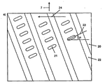
図2は、好ましい実施例によるスクリーニング表面形状をまっすぐにした図を示す。プロファイル・プレート20は、開口21、及び開口21間にあるプロファイル22で形成されている。図から分かるように、本発明による開口21は、スロットである。スロットの形は長方形であり、スロット端部の縁は、角形又は丸形とすることができる。スロットの長さL対幅Wの比は、用途の目的に依存して1.05〜10、好ましくは2〜8である。幅Wは、通常は4〜12mmである。この実施例では、スロット21の長手方向の向き23は、ドラム5の回転方向24に平行である。
FIG. 2 shows a straightened view of the screening surface shape according to the preferred embodiment. The
スロットは、ドラム軸線方向に上下に配置され、スロット列/スロット領域11は、ドラムの円周方向に間隔を置いて形成されている。隆起22、及び鉛直方向のスロット列は、ドラムの鉛直方向軸線に対して位置合せされておらず、傾斜した列である。隆起及びスロット列は、ドラムの鉛直方向シャフト7に対して角度−5〜+20度、通常は15度、すなわち角度βをなしている。
The slots are arranged vertically in the drum axis direction, and the slot row /
鉛直方向のスロット列11の各スロットは、水平方向に平行な列を形成するように水平方向に配置できる。図2は、鉛直方向のスロット列11の各スロット21が、スロット列の各スロットが1列置きに同じ水平方向位置に位置するように水平方向に配置された代替実施例を示す。したがって、鉛直方向のスロット列の各スロットは、鉛直方向のスロット列11の各スロットが1列置きに同じ水平方向位置、すなわち第1の水平方向線群12aに位置するように、かつ、スロット列の各スロットが1列置きに第2の水平方向線群12bに位置するように水平方向に配置される。
Each slot of the
図3では、スロット21の長手方向/長手方向軸線23は、ドラムの回転方向24に対して角度αをなし、この角度は、−40〜+40度である。角度αは、図3aでは約+25度であり、図3bでは約−24度である。
In FIG. 3, the longitudinal /
図4は、プレート20の外面形状を示す。このスクリーニング表面は、隆起22と、隆起22同士の間の平面部分26とを有するプレートで形成されているとみなすことができ、平面部分26には、機械加工された開口21が設けられている。図4の実施例では、隆起がスロット領域に更に設けられ、隆起25は、上下に並んで配置されたスロット間に配置されている。したがって、その場合、その形状は、隆起の列がスロットによって途切れた形となる。スロット領域には、上記のように形成された1つ又は複数の形状を形成でき、これらの形状は、好ましくは、ドラム鉛直方向軸線に対して、スロット列/スロット領域11、及びスロット列/スロット領域11同士の間にある形状体22と同じ傾斜角度である。
FIG. 4 shows the outer shape of the
図5a及び図5bは、スクリーニング表面形状をまっすぐにした断面図を示す。プレート20の内面27は、開口を除いて平坦である。図5bでは、プレート20の外面の隆起22は、プレート20の平面28からある角度で立ち上がった前面29と、プレート20の平面28に実質的に平行な表面30と、プレート20の平面28に実質的に垂直な後面31と、平面28の開口21間にある部分26とから形成されている。他方、スクリーン・プレートは、前記部分29、30、及び31から形成された隆起22と、機械加工された開口21を備えた、隆起22同士の間の平面部分28とを備えたプレートにより形成されるとみなすことができる。図5aの実施例では、前面29がプレートの平面28に垂直であり、後面が傾斜している。
Figures 5a and 5b show cross-sectional views with straightened screening surface shapes. The
流れを受ける外面の隆起の前面が後方に傾斜し、すなわち前面がスクリーニング表面の平面から立ち上がり、後面が垂直である場合(図5b)、この傾斜した前面は、ドラムに入るパルプを、例えばその速度を加速する目的で受けることになるが、いずれにせよスクリーニング表面にあるスクリーニング表面開口を均等に流れる流動が得られる。この流動によって、ある状況下で生じることがある懸濁液の流れが逆方向に乱れることがなくなる。隆起の前面が、スクリーニング表面の平面に垂直であり、隆起の後面が下がっている場合(図5a)、前面は流れに逆らい、流れを混ぜ、それによってスクリーニング表面を通過する流れが増大し、したがって装置の生産能力が増大する。 If the front surface of the outer ridge that receives the flow is inclined backwards, i.e. the front surface rises from the plane of the screening surface and the rear surface is vertical (Fig. 5b), this inclined front surface allows the pulp entering the drum, e.g. In any case, a flow that flows uniformly through the screening surface opening on the screening surface can be obtained. This flow prevents the suspension flow that may occur under certain circumstances from being disturbed in the opposite direction. If the front surface of the ridge is perpendicular to the plane of the screening surface and the back surface of the ridge is lowered (Fig. 5a), the front surface is against the flow and mixes the flow, thereby increasing the flow through the screening surface and thus Equipment production capacity increases.
隆起22は、ドラム軸線、およびドラムの回転方向に対して幾分傾斜していることが図2〜図4から分かる。隆起の傾斜角度、回転方向に対する傾斜の向き、ドラムの回転速度、及び隆起の部分29の立ち上がり角度によって、最終的に得られる分離に応じてスクリーン中でのパルプ循環時間を最適化することが可能となる。隆起22の向きは、隆起22がスクリーン・ドラム5上で後方に傾斜している場合、隆起22によって、繊維懸濁液がスクリーン・ドラムの上方に持ち上がる傾向が生じる。それによって、スクリーン中で繊維懸濁液が循環する時間が増大し、分離がより正確となり、リジェクト量が減少し、アクセプト量が増大するという効果を有する。他方、隆起が前方に傾斜している場合、循環時間が減少し、生産能力が増大する。前記要因に加えて、スクリーン・ドラムの高さもやはり、動作速度、傾斜角度等に影響を及ぼす。
It can be seen from FIGS. 2 to 4 that the
図6の実施例によれば、1つのスロット列にある各スロット21の、ドラムの回転方向24に対する長手方向の向き23の位置は、ドラムのシャフト7に沿って見て上から下に変わっていく(図6a)。最上のスロット21’の長手方向の向きは、ドラムの回転方向に平行(すなわち、ドラム軸線に対して垂直)である。次に下にあるスロット21”の長手方向の向きは、ドラムの回転方向におけるスロット前端32から(ドラム軸線に対して)傾斜し、したがって(ドラムの回転方向における)スロット前端32は、その後端33よりも上に位置している。したがって、次に下にあるスロットは、上にあるスロットよりも下方に傾斜している。下にあるスロットの傾斜角度は、通常は1〜5度、通常は2〜4度大きい。この種の実施例では、スロットの向きの変化は、上から下へと下がっていくと考えることができる。別の実施例(図6b)によれば、最上スロットの長手方向の向きは、ドラムの回転方向に平行であるが、後続の下にあるスロットは、回転方向に対して上方に傾斜し、したがってドラムの回転方向における前記スロット前端32’は、その後端33’よりも下に位置している。したがって、次に下にあるスロットの後端は、その上にあるスロットよりも大きく上方に傾斜している。下にあるスロットの傾斜角度は、1〜5度、通常は2〜4度大きい。この種の実施例では、スロットの向きの変化は、上から下へと上がっていくと考えることができる。これらの実施例では、上下に配置された2つのスロットは、実質的に平行でよいが、1つのスロット列にあるスロットの大部分を互いに異なる傾斜角度で配置することが適切である。
According to the embodiment of FIG. 6, the position of each
本発明の好ましい実施例(図6c、d)によれば、1つのスロット列にある各スロットの、ドラムの回転方向に対する長手方向の向きの位置/角度は、ドラム軸線に沿って見て下から上に変わっていき、最下スロットの長手方向の向きは、ドラムの回転方向に平行であるが、次に上に位置するスロットは、回転方向に対して傾斜している。したがって、次に上にあるスロットは、上方に傾斜しており(図6c)、したがってドラムの回転方向におけるスロット前端32”は、そのスロット後端33”よりも下に位置している。通常は、上にあるスロットは、下にあるスロットよりも傾斜している。上にあるスロットの傾斜角度は、1〜5度、通常は2〜4度大きい。この種の実施例では、スロットの向きの変化は、下から上に上がっていくと考えることができる。本発明の好ましい実施例(図6d)によれば、上にあるスロットを、ドラムの回転方向におけるスロット前端32’’’が、そのスロット後端33’’’よりも上に位置するように、同様に傾斜させてもよい。その場合、スロットは、回転方向に対して下方に傾斜することになる。この種の実施例では、スロットの向きの変化は、下から上に下がっていくと考えることができる。
According to a preferred embodiment of the present invention (FIGS. 6c, d), the position / angle of each slot in a row of slots in the longitudinal direction relative to the direction of rotation of the drum is from below as viewed along the drum axis. Turning upward, the longitudinal orientation of the bottom slot is parallel to the direction of rotation of the drum, but the slot located next up is inclined with respect to the direction of rotation. The next upper slot is therefore inclined upwards (FIG. 6c), so that the slot
スロットが下方に傾斜する実施例(図6a及び図6d)では、より高い生産能力が得られる。スロットが上方に傾斜する実施例(図6b及び図6c)では、汚染粒子が上から下方へと流れるため、より高い清浄度が得られる。 In the embodiment in which the slots are inclined downwards (FIGS. 6a and 6d), a higher production capacity is obtained. In the embodiment in which the slots are inclined upwards (FIGS. 6b and 6c), higher cleanliness is obtained because the contaminating particles flow from top to bottom.
上記から明白となるように、本発明による方法及び装置によって、従来技術による装置及び方法の欠点が解消され、したがってスクリーニング装置の生産能力を増大させることが可能となった。しかし、上記では、本発明の最も重要な実施例のいくつかをより詳細に説明したにすぎず、これらの実施例は、本発明の保護範囲を単独で規定する特許請求の範囲の記載事項から本発明を限定するものではないことに留意されたい。 As will be apparent from the above, the method and apparatus according to the present invention have eliminated the disadvantages of the prior art apparatus and method, and thus have made it possible to increase the production capacity of the screening apparatus. However, the foregoing has only described some of the most important embodiments of the present invention in more detail, and these embodiments are not limited to the claims that define the protection scope of the present invention alone. It should be noted that the present invention is not limited.
Claims (15)
ケーシング(1)と、
繊維懸濁液用の供給導管(2)並びにリジェクト用及びアクセプト用の出口導管(4、3)と、
前記ケーシング内で鉛直方向のシャフト(7)の周りで回転できるように配置され、アクセプト部分が流れる開口(21)が設けられたスクリーニング表面(20)を有するスクリーン・ドラム(5)と
を備え、前記供給導管及び出口導管は、前記繊維懸濁液が前記ケーシングと前記スクリーン・ドラムとの間にある空間(8)に供給され、前記アクセプト部分が前記スクリーン・ドラムの内側から排出されるように配置された前記装置において、
前記スクリーニング表面にある前記開口は、前記ドラムの回転方向に対する長手方向の向きが−40〜+40度であり、長さ対幅の比が1.05〜10であるスロット(21)であり、該スロットが、スロット列(11)を形成すること、及び前記スクリーニング表面の外面が、前記スロット列間に隆起(22)が配置されるように形成されることを特徴とする、繊維懸濁液をスクリーニングする装置。 An apparatus for screening a fiber suspension, especially an apparatus for removing coarse particles such as knots, the apparatus comprising:
A casing (1);
A supply conduit (2) for the fiber suspension and an outlet conduit (4, 3) for rejection and acceptance;
A screen drum (5) having a screening surface (20) arranged in the casing for rotation around a vertical shaft (7) and provided with an opening (21) through which the accepting portion flows, The supply conduit and outlet conduit are such that the fiber suspension is supplied to a space (8) between the casing and the screen drum, and the accepting portion is discharged from the inside of the screen drum. In the arranged device,
The opening in the screening surface is a slot (21) having a longitudinal orientation with respect to the direction of rotation of the drum of -40 to +40 degrees and a length to width ratio of 1.05 to 10, A fiber suspension characterized in that the slots form a row of slots (11) and the outer surface of the screening surface is formed such that ridges (22) are arranged between the rows of slots. Screening device.
Applications Claiming Priority (3)
| Application Number | Priority Date | Filing Date | Title |
|---|---|---|---|
| FI20095769A FI20095769A (en) | 2009-07-07 | 2009-07-07 | Apparatus for handling a fiber suspension |
| FI20095769 | 2009-07-07 | ||
| PCT/FI2010/050482 WO2011004060A1 (en) | 2009-07-07 | 2010-06-10 | Apparatus for screening fibre suspensions |
Publications (1)
| Publication Number | Publication Date |
|---|---|
| JP2012532999A true JP2012532999A (en) | 2012-12-20 |
Family
ID=40935850
Family Applications (1)
| Application Number | Title | Priority Date | Filing Date |
|---|---|---|---|
| JP2012519028A Abandoned JP2012532999A (en) | 2009-07-07 | 2010-06-10 | Equipment for screening fiber suspensions |
Country Status (7)
| Country | Link |
|---|---|
| EP (1) | EP2452012B1 (en) |
| JP (1) | JP2012532999A (en) |
| CN (1) | CN102472008A (en) |
| BR (1) | BRPI1014007A2 (en) |
| FI (1) | FI20095769A (en) |
| RU (1) | RU2012104023A (en) |
| WO (1) | WO2011004060A1 (en) |
Cited By (1)
| Publication number | Priority date | Publication date | Assignee | Title |
|---|---|---|---|---|
| JP2015120317A (en) * | 2013-12-25 | 2015-07-02 | セイコーエプソン株式会社 | Sheet manufacturing apparatus |
Families Citing this family (1)
| Publication number | Priority date | Publication date | Assignee | Title |
|---|---|---|---|---|
| KR101438798B1 (en) * | 2012-02-08 | 2014-09-05 | 서울대학교산학협력단 | Method for cooperative operation between macrocell base station and femtocell base station |
Family Cites Families (9)
| Publication number | Priority date | Publication date | Assignee | Title |
|---|---|---|---|---|
| US1631585A (en) * | 1927-06-07 | Screen plate | ||
| US3713541A (en) * | 1971-05-10 | 1973-01-30 | Bird Machine Co | Screening machine with slotted screen |
| SE450711B (en) * | 1985-11-14 | 1987-07-20 | Besam Ag | screening member |
| FI76139C (en) * | 1987-01-19 | 1988-09-09 | Ahlstroem Oy | Twigs separation method and apparatus |
| US4795560A (en) * | 1987-04-16 | 1989-01-03 | The Black Clawson Company | Screen plates |
| CN2069430U (en) * | 1990-07-20 | 1991-01-16 | 上海造纸机械总厂沪光分厂 | Special-shaped screen board |
| FI89521C (en) * | 1991-10-04 | 1993-10-11 | Cae Investments Bv | Process for producing a screen product and by the process for produced screen product |
| DE10217926A1 (en) * | 2002-04-23 | 2003-11-13 | Voith Paper Patent Gmbh | Process for wet screening of fiber suspensions |
| DE502006008007D1 (en) * | 2005-10-19 | 2010-11-18 | Voith Patent Gmbh | Screening device for wet screening of paper fiber suspensions |
-
2009
- 2009-07-07 FI FI20095769A patent/FI20095769A/en not_active IP Right Cessation
-
2010
- 2010-06-10 RU RU2012104023/12A patent/RU2012104023A/en not_active Application Discontinuation
- 2010-06-10 CN CN2010800306089A patent/CN102472008A/en active Pending
- 2010-06-10 BR BRPI1014007A patent/BRPI1014007A2/en not_active IP Right Cessation
- 2010-06-10 WO PCT/FI2010/050482 patent/WO2011004060A1/en active Application Filing
- 2010-06-10 JP JP2012519028A patent/JP2012532999A/en not_active Abandoned
- 2010-06-10 EP EP10796769.7A patent/EP2452012B1/en not_active Not-in-force
Cited By (1)
| Publication number | Priority date | Publication date | Assignee | Title |
|---|---|---|---|---|
| JP2015120317A (en) * | 2013-12-25 | 2015-07-02 | セイコーエプソン株式会社 | Sheet manufacturing apparatus |
Also Published As
| Publication number | Publication date |
|---|---|
| EP2452012B1 (en) | 2014-01-15 |
| FI20095769A0 (en) | 2009-07-07 |
| FI20095769A (en) | 2011-01-08 |
| BRPI1014007A2 (en) | 2016-04-12 |
| EP2452012A4 (en) | 2012-12-05 |
| WO2011004060A1 (en) | 2011-01-13 |
| RU2012104023A (en) | 2013-08-20 |
| CN102472008A (en) | 2012-05-23 |
| EP2452012A1 (en) | 2012-05-16 |
Similar Documents
| Publication | Publication Date | Title |
|---|---|---|
| US4356085A (en) | Rotary screening machine for pulp suspensions | |
| US4202761A (en) | Sorting apparatus for sorting fiber suspensions | |
| US20130206881A1 (en) | Pulper comprising a screening sheet | |
| US20010045379A1 (en) | Screen | |
| US6284096B1 (en) | Process for discharging impurities from a hydrocyclone and a hydrocyclone | |
| CA1064428A (en) | Stationary cylindrical screen for liquid suspensions including a heavy impurities trap and dilution means | |
| JP2012532999A (en) | Equipment for screening fiber suspensions | |
| CN1201049C (en) | Pulp-screening device | |
| US6669025B2 (en) | Screen | |
| US4571298A (en) | Sorting screen | |
| US3970548A (en) | Apparatus for screening paper fiber stock | |
| US6499603B2 (en) | Screen for cleaning pulp suspensions | |
| US5143220A (en) | Apparatus for screening to remove knots from a fluid borne slurry of fibers and knots | |
| US20230060771A1 (en) | Pulp Screening Machine | |
| US6631809B2 (en) | Screen for cleaning a pulp suspension | |
| JPS63249792A (en) | Method and apparatus for separating undigested substance | |
| JP6826416B2 (en) | Sand separator, replaceable perforated insert device and method | |
| MXPA01001293A (en) | Screen. | |
| JP6377159B2 (en) | Pressurized sorter | |
| KR840000554B1 (en) | Rotational separator | |
| JP2002285489A (en) | Screen device | |
| WO2004046457A1 (en) | Method and apparatus for treating fiber suspension | |
| JPH086274B2 (en) | Stock screen | |
| WO2014182232A1 (en) | An apparatus for separating particles in a pulp suspension | |
| JP2002285485A (en) | Screen device |
Legal Events
| Date | Code | Title | Description |
|---|---|---|---|
| A621 | Written request for application examination |
Free format text: JAPANESE INTERMEDIATE CODE: A621 Effective date: 20130108 |
|
| A762 | Written abandonment of application |
Free format text: JAPANESE INTERMEDIATE CODE: A762 Effective date: 20130906 |