JP2012521801A - Management of pain with subthreshold stimuli for illusion - Google Patents
Management of pain with subthreshold stimuli for illusion Download PDFInfo
- Publication number
- JP2012521801A JP2012521801A JP2012502199A JP2012502199A JP2012521801A JP 2012521801 A JP2012521801 A JP 2012521801A JP 2012502199 A JP2012502199 A JP 2012502199A JP 2012502199 A JP2012502199 A JP 2012502199A JP 2012521801 A JP2012521801 A JP 2012521801A
- Authority
- JP
- Japan
- Prior art keywords
- stimulation energy
- dorsal root
- level
- root ganglion
- lead
- Prior art date
- Legal status (The legal status is an assumption and is not a legal conclusion. Google has not performed a legal analysis and makes no representation as to the accuracy of the status listed.)
- Pending
Links
Images


Classifications
-
- A—HUMAN NECESSITIES
- A61—MEDICAL OR VETERINARY SCIENCE; HYGIENE
- A61N—ELECTROTHERAPY; MAGNETOTHERAPY; RADIATION THERAPY; ULTRASOUND THERAPY
- A61N1/00—Electrotherapy; Circuits therefor
- A61N1/02—Details
- A61N1/04—Electrodes
- A61N1/05—Electrodes for implantation or insertion into the body, e.g. heart electrode
- A61N1/0551—Spinal or peripheral nerve electrodes
-
- A—HUMAN NECESSITIES
- A61—MEDICAL OR VETERINARY SCIENCE; HYGIENE
- A61N—ELECTROTHERAPY; MAGNETOTHERAPY; RADIATION THERAPY; ULTRASOUND THERAPY
- A61N1/00—Electrotherapy; Circuits therefor
- A61N1/18—Applying electric currents by contact electrodes
- A61N1/32—Applying electric currents by contact electrodes alternating or intermittent currents
- A61N1/36—Applying electric currents by contact electrodes alternating or intermittent currents for stimulation
- A61N1/36014—External stimulators, e.g. with patch electrodes
- A61N1/36021—External stimulators, e.g. with patch electrodes for treatment of pain
-
- A—HUMAN NECESSITIES
- A61—MEDICAL OR VETERINARY SCIENCE; HYGIENE
- A61N—ELECTROTHERAPY; MAGNETOTHERAPY; RADIATION THERAPY; ULTRASOUND THERAPY
- A61N1/00—Electrotherapy; Circuits therefor
- A61N1/18—Applying electric currents by contact electrodes
- A61N1/32—Applying electric currents by contact electrodes alternating or intermittent currents
- A61N1/36—Applying electric currents by contact electrodes alternating or intermittent currents for stimulation
- A61N1/3605—Implantable neurostimulators for stimulating central or peripheral nerve system
- A61N1/3606—Implantable neurostimulators for stimulating central or peripheral nerve system adapted for a particular treatment
- A61N1/36071—Pain
-
- A—HUMAN NECESSITIES
- A61—MEDICAL OR VETERINARY SCIENCE; HYGIENE
- A61N—ELECTROTHERAPY; MAGNETOTHERAPY; RADIATION THERAPY; ULTRASOUND THERAPY
- A61N1/00—Electrotherapy; Circuits therefor
- A61N1/18—Applying electric currents by contact electrodes
- A61N1/32—Applying electric currents by contact electrodes alternating or intermittent currents
- A61N1/36—Applying electric currents by contact electrodes alternating or intermittent currents for stimulation
- A61N1/3605—Implantable neurostimulators for stimulating central or peripheral nerve system
- A61N1/36128—Control systems
- A61N1/36146—Control systems specified by the stimulation parameters
- A61N1/3615—Intensity
- A61N1/36157—Current
-
- A—HUMAN NECESSITIES
- A61—MEDICAL OR VETERINARY SCIENCE; HYGIENE
- A61N—ELECTROTHERAPY; MAGNETOTHERAPY; RADIATION THERAPY; ULTRASOUND THERAPY
- A61N1/00—Electrotherapy; Circuits therefor
- A61N1/18—Applying electric currents by contact electrodes
- A61N1/32—Applying electric currents by contact electrodes alternating or intermittent currents
- A61N1/36—Applying electric currents by contact electrodes alternating or intermittent currents for stimulation
- A61N1/36014—External stimulators, e.g. with patch electrodes
- A61N1/36017—External stimulators, e.g. with patch electrodes with leads or electrodes penetrating the skin
Abstract
合併症の可能性および望ましくない副次的な悪影響、特に錯感覚の感覚、を最小限に止め若しくは排除しながら、疼痛を治療するための装置,システム及び方法が提供される。このことは、錯感覚の実質的な感覚を生じさせることなく疼痛感覚に作用するやり方で、刺激エネルギーレベルでもって、後根の神経節に近接して刺激を加えることにより達成される。幾つかの実施形態では、かかる神経刺激は、後根の神経節に特有の生体構造上の特徴および機能を旨く利用している。Devices, systems and methods are provided for treating pain while minimizing or eliminating the possibility of complications and undesirable side effects, particularly the sensation of illusion. This is accomplished by applying a stimulus close to the dorsal root ganglion with a stimulus energy level in a manner that affects the pain sensation without producing a substantial sense of illusion. In some embodiments, such neural stimulation takes advantage of the anatomical features and functions unique to dorsal root ganglia.
Description
(関連出願の相互参照)
この出願は、参照することによりここに組み入れられるものであるが、2009年3月24日に出願された「閾値以下の刺激を伴う疼痛の管理」と題する米国仮特許出願第61/163,007号に対する35 U.S.C. 119(e)に基づく優先権を主張するものである。
(Cross-reference of related applications)
This application, which is incorporated herein by reference, is a US Provisional Patent Application No. 61 / 163,007 entitled “Management of Pain with Subthreshold Stimulation” filed Mar. 24, 2009. Claims priority under 35 USC 119 (e).
(連邦政府支援の研究または開発の下でなされた発明に対する権利に関する陳述)
:該当せず
(Statement regarding rights to inventions made under federal-sponsored research or development)
:Not applicable
(「配列表」,表、若しくはコンパクトディスクに関して提出されたコンピュータプログラム表の付属書類への言及)
:該当せず
(Reference to “Sequence Listing”, Table, or Appendix to Computer Program Table Submitted for Compact Disc)
:Not applicable
脊髄刺激法(spinal cord stimulation:SCS)は、30年以上にわたって、様々な疼痛症候群の治療に用いられてきた。SCSの目標は、痛みのある部位は完全に且つ一貫してカバー(cover)するけれども、他の部位においては不快な感覚を生じさせることのない、錯感覚(パレステジア:paresthesia)を創り出すことである。錯感覚は、身体の部位における、ひりひり感(tingling),ちくちく感(pricking)、或いは痺れ感(numbness)の感覚として定義付けることができる。この錯感覚は、より一般的には、「ピリピリ感(pins and needles)」の感覚として知られている。幾つかの事例では、錯感覚の感覚は、痛みの感覚よりも好ましい。
SCSにおいては、錯感覚の創出は、脊髄後索(dorsal column)および/または後根(dorsal root)のAβ繊維を刺激することによって達成される。脊髄後索刺激は、典型的には、刺激器(stimulator)のレベル(level)及びそれを下回るレベルにて、多くの皮節において錯感覚を生じせしめる。これとは対照的に、後根刺激は、刺激器にごく近接した限られた数の細根(rootlet)内の繊維を活性化させて、僅かな数の皮節のみにおいて錯感覚を生じせしめる。
これらの要因のために、SCS刺激器を用いての後根刺激は、十分な疼痛緩和(pain relief)をもたらさないかも知れない。更に、SCS刺激器を用いての根(root)の刺激は、不快な感覚や運動機能(motor response)を生じせしめることがある。これらの副次的な悪影響は、錯感覚の全範囲に対して必要とされる値を下回るパルス振幅で起こり得る。従って、SCSの臨床上の目標は、神経根付近を刺激することなく、関連のある脊髄構造を刺激する電場を創り出すことである。
Spinal cord stimulation (SCS) has been used for the treatment of various pain syndromes for over 30 years. The goal of SCS is to create an illusion (paresthesia) that covers the painful area completely and consistently, but does not create an unpleasant sensation elsewhere. . Illusion can be defined as a sensation of tingling, pricking, or numbness in the body part. This illusion is more commonly known as a “pins and needles” sensation. In some cases, an illusionary sensation is preferred over a pain sensation.
In SCS, the creation of illusion is achieved by stimulating Aβ fibers in the dorsal column and / or dorsal root. Back spinal cord stimulation typically causes illusions in many dermatomes at and below the level of the stimulator. In contrast, dorsal root stimulation activates the fibers in a limited number of rootlets in close proximity to the stimulator, creating an illusion in only a few dermatomes.
Because of these factors, dorsal root stimulation with an SCS stimulator may not provide sufficient pain relief. In addition, root stimulation with an SCS stimulator can cause unpleasant sensations and motor responses. These side effects can occur at pulse amplitudes below that required for the full range of illusion. Thus, the clinical goal of SCS is to create an electric field that stimulates the relevant spinal cord structures without stimulating near the nerve roots.
髄腔内神経根刺激は、脊髄の正中線上ではなく、脊柱管の外側面(この領域は「ガター(gutter)」として知られている)の神経細根に沿って、電極が配置される点を除いては、SCSに関連した技法である。電極は、伝統的なSCSパドルリード(paddle lead)ではなく、円筒リード(cylindrical lead)に取り付けられる。ガター内でのリード線配置の精度は、局所内での錯感覚をもたらす知覚可能なレベルで神経根を刺激することによって確認される。知覚上の回復(sensory recruitment)に対する閾値を上回るレベルで刺激することにより、知覚上の錯感覚(sensory paresthesia)が生じ得る。この技法は、ある種の疼痛状態を治療するために、SCSと併せて用いることができる。 Intrathecal nerve root stimulation refers to the point where electrodes are placed along the nerve root of the lateral surface of the spinal canal (this region is known as the “gutter”), not on the midline of the spinal cord. Except for SCS related techniques. The electrode is attached to a cylindrical lead rather than a traditional SCS paddle lead. The accuracy of the lead placement within the gutter is confirmed by stimulating the nerve roots at a perceptible level that results in local illusion. Stimulating at levels above the threshold for sensory recruitment can result in sensory paresthesia. This technique can be used in conjunction with SCS to treat certain pain conditions.
ある種の患者にとっては、錯感覚は望ましい効果ではなく、また、疼痛に対する耐性の高い代替手段ではない。従って、望ましくない効果を最小限にして疼痛緩和をもたらすには、改良された治療法が必要とされている。これらの目的の少なくとも幾つかは、本発明によってかなえられることになろう。 For some patients, illusion is not a desirable effect and is not a pain-resistant alternative. Therefore, improved therapies are needed to provide pain relief with minimal undesirable effects. At least some of these objectives will be met by the present invention.
(発明の概要)
本発明は、合併症(complication)の可能性および望ましくない副次的な悪影響を、最小限に止め若しくは排除しながら、例えば疼痛などの状態を治療するための装置,システム及び方法を提供するものである。特に、この装置,システム及び方法は、錯感覚の実質的な感覚を生じさせることなく、疼痛を治療する。このことは、ここでより詳しく説明されるように、特定の刺激エネルギーレベルでもって、後根の神経節(ガングリオン:ganglion)に極めて近接して刺激を加えることによって達成される。
(Summary of Invention)
The present invention provides an apparatus, system and method for treating conditions such as pain, while minimizing or eliminating the possibility of complications and undesirable side effects. It is. In particular, the devices, systems and methods treat pain without creating a substantial sense of illusion. This is accomplished by applying a stimulus in close proximity to the dorsal root ganglion with a specific stimulus energy level, as described in more detail herein.
本発明の第1の態様においては、少なくとも1つの電極を有するリード線を位置決めするステップであって、前記少なくとも1つの電極の少なくとも1つが、後根神経節に近接するように位置決めするステップと、前記後根神経節の少なくとも一部を刺激するために、前記少なくとも1つの電極の少なくとも1つに刺激エネルギーを供給するステップとを備える、患者の疼痛を治療するための方法が提供されている。前記リード線の位置決めステップと前記刺激エネルギーの供給ステップとが合わさって、実質的な錯感覚の感覚を生じせしめることなく疼痛感覚に作用する。 In a first aspect of the invention, positioning a lead having at least one electrode, wherein at least one of the at least one electrode is positioned proximate to a dorsal root ganglion; Providing stimulation energy to at least one of the at least one electrode to stimulate at least a portion of the dorsal root ganglion is provided. The lead positioning step and the stimulation energy supply step combine to act on the pain sensation without causing a substantial sense of illusion.
幾つかの実施形態では、前記刺激エネルギーを供給するステップは、Aβ繊維の補給のための閾値以下のレベルで刺激エネルギーを供給することを包含している。また、幾つかの実施形態では、前記刺激エネルギーを供給するステップは、Aβ繊維のセルボディ補給のための閾値以下のレベルで刺激エネルギーを供給することを包含している。 In some embodiments, providing the stimulation energy includes providing stimulation energy at a sub-threshold level for Aβ fiber supplementation. Also, in some embodiments, supplying the stimulation energy includes supplying stimulation energy at a level below a threshold for cell body supplementation of Aβ fibers.
別の実施形態では、前記刺激エネルギーを供給するステップは、a)Aδ繊維のセルボディ補給のための閾値を越えるレベルで刺激エネルギーを供給すること、b)C繊維のセルボディ補給のための閾値を越えるレベルで刺激エネルギーを供給すること、c)髄鞘が有る小型の繊維のセルボディ補給のための閾値を越えるレベルで刺激エネルギーを供給すること、d)髄鞘が無い繊維のセルボディ補給のための閾値を越えるレベルで刺激エネルギーを供給すること、を包含している。 In another embodiment, the step of providing stimulation energy comprises a) providing stimulation energy at a level that exceeds a threshold for cell body supplementation of Aδ fibers, and b) exceeding a threshold for cell body supplementation of C fibers. Providing stimulation energy at a level, c) providing stimulation energy at a level that exceeds the threshold for cell body supplementation of small fibers with myelin sheath, d) threshold for cell body supplementation of fiber without myelin sheath Providing stimulation energy at a level exceeding.
更に別の実施形態では、前記刺激エネルギーを供給するステップは、前記後根神経節内のグリア細胞の機能を調節することができるレベルで刺激エネルギーを供給することを包含している。例えば、幾つかの実施形態では、前記刺激エネルギーを供給するステップは、前記後根神経節内の衛生細胞の機能を調節することができるレベルで刺激エネルギーを供給することを包含している。また、別の実施形態では、前記刺激エネルギーを供給するステップは、前記後根神経節内のシュワン細胞の機能を調節することができるレベルで刺激エネルギーを供給することを包含している。 In yet another embodiment, providing the stimulation energy includes providing stimulation energy at a level that can modulate the function of glial cells in the dorsal root ganglion. For example, in some embodiments, providing the stimulation energy includes providing stimulation energy at a level that can modulate the function of sanitary cells in the dorsal root ganglion. In another embodiment, supplying the stimulation energy includes supplying the stimulation energy at a level that can regulate the function of Schwann cells in the dorsal root ganglion.
更になお別の実施形態では、前記刺激エネルギーを供給するステップは、前記後根神経節内のニューロン若しくはグリア細胞に連繋する少なくとも1つの血管に、作用物質を放出するか、又は後根神経節内のニューロン若しくはグリア細胞に作用する細胞信号を送らせる、ことができるレベルで刺激エネルギーを供給することを包含している。 In still yet another embodiment, supplying the stimulation energy releases the agent to at least one blood vessel connected to neurons or glial cells in the dorsal root ganglion, or within the dorsal root ganglion. Providing stimulation energy at a level capable of sending cellular signals that act on the neurons or glial cells.
幾つかの実施形態では、前記リード線を位置決めするステップは、前記リード線の少なくとも一部が神経根スリーブの角度姿勢に沿って伸長するように、前記リード線を硬膜上腔を通って進行させることを包含している。また、幾つかの実施形態では、前記リード線を硬膜上腔を通って順行方向に進行させるステップは、順行方向に進行させることを包含している。 In some embodiments, positioning the lead advances the lead through the epidural space such that at least a portion of the lead extends along the angular orientation of the nerve root sleeve. Is included. In some embodiments, the step of advancing the lead wire through the epidural space in the antegrade direction includes advancing in the antegrade direction.
本発明の第2の態様においては、患者の後根神経節と共にAβ繊維セルボディを除きつつ、当該患者の後根神経節内の小型の繊維セルボディを選択的に刺激する、患者を治療するための方法が提供されている。
幾つかの実施形態では、前記小型の繊維セルボディはAδ繊維セルボディを包含している。また、別の実施形態では、前記小型の繊維セルボディはC繊維セルボディを包含している。
In a second aspect of the present invention, for treating a patient, the Aβ fiber cell body is removed together with the patient's dorsal root ganglion while selectively stimulating small fiber cell bodies in the patient's dorsal root ganglion. A method is provided.
In some embodiments, the small fiber cell body includes an Aδ fiber cell body. In another embodiment, the small fiber cell body includes a C fiber cell body.
本発明の第3の態様においては、患者による疼痛の感覚に関連した後根神経節を特定するステップと、患者による疼痛の感覚を低減するために、前記後根神経節内の少なくとも1つのグリア細胞を神経調節するステップとを備えた、患者を治療するための方法が提供されている。
幾つかの実施形態では、前記少なくとも1つのグリア細胞は衛生細胞を包含している。別の実施形態では、前記少なくとも1つのグリア細胞はシュワン細胞を包含している。また、幾つかの実施形態では、前記神経調節するステップは、実質的な錯感覚の感覚を生じせしめることなく疼痛感覚を抑制するレベルで刺激を与えることを包含している。
In a third aspect of the present invention, identifying a dorsal root ganglion associated with a sensation of pain by the patient, and reducing at least one glia in the dorsal root ganglion to reduce the sensation of pain by the patient. There is provided a method for treating a patient comprising the step of neuromodulating cells.
In some embodiments, the at least one glial cell includes a sanitary cell. In another embodiment, the at least one glial cell includes a Schwann cell. In some embodiments, the neuromodulating step includes providing a stimulus at a level that suppresses pain sensation without causing a substantial sensory sensation.
本発明の第4の態様においては、少なくとも1つの電極を有するリード線を位置決めするステップであって、前記少なくとも1つの電極の少なくとも1つが、後根神経節に近接するように位置決めするステップと、少なくとも1つの血管が後根神経節内のニューロンを細胞調節する作用物質を放出せしめるように、前記後根神経節に連繋した前記少なくとも1つの血管を刺激するように、前記少なくとも1つの電極に刺激エネルギーを供給するステップとを備えた、患者を治療するための方法が提供されている。
幾つかの実施形態では、前記作用物質は、疼痛感覚の変換に関与するニューロンの機能に作用する細胞調節薬品を包含している。
In a fourth aspect of the invention, positioning a lead having at least one electrode, wherein at least one of the at least one electrode is positioned proximate to a dorsal root ganglion; Stimulate the at least one electrode to stimulate the at least one blood vessel connected to the dorsal root ganglion such that at least one blood vessel releases an agent that regulates neurons in the dorsal root ganglion A method is provided for treating a patient comprising providing energy.
In some embodiments, the agent includes a cytoregulatory agent that affects the function of neurons involved in the conversion of pain sensation.
本発明の第5の態様においては、患者の疼痛を治療するために、少なくとも1つの電極を有するリード線であって、後根神経節に近接して配置されるように構成されたリード線と、実質的な錯感覚の感覚を生じせしめることなく疼痛感覚に作用するように、前記後根神経節を刺激するために、前記リード線が前記後根神経節に近接して位置決めされている間、前記少なくとも1つの電極の少なくとも1つに刺激エネルギーを供給するように構成された、パルス発生器とを備えているシステムが提供されている。 In a fifth aspect of the present invention, a lead having at least one electrode for treating pain in a patient, the lead configured to be placed proximate to a dorsal root ganglion; While the lead is positioned proximate to the dorsal root ganglion to stimulate the dorsal root ganglion to act on pain sensation without causing a substantial sensory sensation And a pulse generator configured to provide stimulation energy to at least one of the at least one electrode.
幾つかの実施形態では、前記パルス発生器は、Aβ繊維の補給のための閾値以下のレベルで刺激エネルギーを供給する。別の実施形態では、前記パルス発生器は、Aβ繊維のセルボディ補給のための閾値以下のレベルで刺激エネルギーを供給する。また、別の実施形態では、前記パルス発生器は、Aδ繊維のセルボディ補給のための閾値を越えるレベルで刺激エネルギーを供給する。更に別の実施形態では、前記パルス発生器は、C繊維のセルボディ補給のための閾値を越えるレベルで刺激エネルギーを供給する。幾つかの実施形態では、前記パルス発生器は、髄鞘が有る小型の繊維のセルボディ補給のための閾値を越えるレベルで刺激エネルギーを供給する。また、幾つかの実施形態では、前記パルス発生器は、髄鞘が無い繊維のセルボディ補給のための閾値を越えるレベルで刺激エネルギーを供給する。 In some embodiments, the pulse generator delivers stimulation energy at a sub-threshold level for Aβ fiber supplementation. In another embodiment, the pulse generator provides stimulation energy at a sub-threshold level for Aβ fiber cell body replenishment. In another embodiment, the pulse generator supplies stimulation energy at a level that exceeds a threshold for cell body replenishment of Aδ fibers. In yet another embodiment, the pulse generator delivers stimulation energy at a level that exceeds a threshold for C fiber cell body replenishment. In some embodiments, the pulse generator delivers stimulation energy at a level that exceeds a threshold for cell body replenishment of small fibers with myelin sheaths. Also, in some embodiments, the pulse generator provides stimulation energy at a level that exceeds a threshold for cell body supplementation of fibers without myelin sheaths.
幾つかの実施形態では、前記パルス発生器は、前記後根神経節内のグリア細胞の機能を調節することができるレベルで刺激エネルギーを供給する。例えば、幾つかの実施形態では、前記パルス発生器は、前記後根神経節内の衛生細胞の機能を調節することができるレベルで刺激エネルギーを供給する。また、別の実施形態では、前記パルス発生器は、前記後根神経節内のシュワン細胞の機能を調節することができるレベルで刺激エネルギーを供給する。 In some embodiments, the pulse generator provides stimulation energy at a level that can regulate the function of glial cells in the dorsal root ganglion. For example, in some embodiments, the pulse generator provides stimulation energy at a level that can regulate the function of sanitary cells in the dorsal root ganglion. In another embodiment, the pulse generator supplies stimulation energy at a level that can regulate the function of Schwann cells in the dorsal root ganglion.
幾つかの事例では、前記パルス発生器は、前記後根神経節内のニューロン若しくはグリア細胞に連繋する少なくとも1つの血管に、作用物質を放出するか、又は後根神経節内のニューロン若しくはグリア細胞に作用する細胞信号を送らせる、ことができるレベルで刺激エネルギーを供給する。 In some cases, the pulse generator releases an agent to at least one blood vessel that communicates with neurons or glial cells in the dorsal root ganglion or neurons or glial cells in the dorsal root ganglion. It supplies stimulation energy at a level that allows it to send cellular signals that act on it.
また、幾つかの実施形態では、前記リード線は、硬膜上腔を通って順行方向に進行させられるように構成され、前記リード線の少なくとも一部が神経根スリーブの角度姿勢に沿って伸長するように位置決めされる。 In some embodiments, the lead wire is configured to be advanced in an antegrade direction through the epidural space, and at least a portion of the lead wire is along the angular orientation of the nerve root sleeve. Positioned to extend.
本発明の他の目的および利点は、添付図面に従い添付図面を伴った詳細な説明から明らかになることであろう。 Other objects and advantages of the present invention will become apparent from the detailed description taken in conjunction with the accompanying drawings.
本発明は、合併症の可能性および望ましくない副次的な悪影響を、特に錯感覚の感覚を、最小限に止め若しくは排除しながら、疼痛を治療するための装置,システム及び方法を提供するものである。このことは、錯感覚の実質的な感覚を生じさせることなく疼痛感に影響を及ぼすことになる手法で、刺激エネルギーレベルでもって後根の神経節(ガングリオン)に極めて近接して刺激を加えることによって達成される。
幾つかの実施形態では、かかる神経刺激は、以下により詳しく説明されるように、後根の神経節に特有の解剖学上の特徴および機能を巧みに利用している。この装置,システム及び方法は、侵襲性が最小限であり、従って、移植手術に起因する合併症の可能性を低減し、また、錯感覚のような知覚が最小で、若しくは全く伴わずに、疼痛感をなんとかするように目標付けられている。
The present invention provides an apparatus, system and method for treating pain while minimizing or eliminating possible complications and undesirable side effects, particularly the illusionary sensation. It is. This is a technique that will affect the feeling of pain without creating a substantial sense of illusion, applying a stimulus very close to the dorsal root ganglion (ganglion) with a stimulus energy level. Achieved by:
In some embodiments, such neural stimulation takes advantage of anatomical features and functions unique to dorsal root ganglia, as described in more detail below. This device, system and method is minimally invasive, thus reducing the possibility of complications resulting from transplant surgery and with minimal or no perception such as illusion. It is targeted to manage pain.
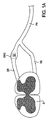
図1Aは、脊髄S,連繋する神経根(nerve root)および脊髄レベルでの末梢神経の概略的な図解をもたらす図である。ここに、神経根は、末梢神経(peripheral nerve)PNで繋がって一緒になる後根(dorsal root)DR及び前根(ventral root)VRを包含している。図に示されるように、前記後根DRは後根神経節(dorsal root ganglion)DRGを含んでいる。DRGは、大型ニューロン(neuron),小型ニューロン及び非神経(非ニューロン:non-neuronal)細胞を含む、様々の細胞(セル:cell)で構成されている。
DRG内の各ニューロンは、体細胞(ソーマ:細胞核を包含する神経の球状の端部)及び2つの軸索(axon)を有する、双極性または擬似的に単極性の細胞で構成されている。用語ソーマ(soma:体細胞)はギリシャ語であって「ボディ(body)」を意味し;神経のソーマはよく「セルボディ(cell body)」と呼ばれる。ソーマは、後根ではなくてDRG内に集められ、連繋する軸索は、そこから後根内へ、及び末梢神経系へ向かって伸長する。
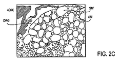
図1Bは、DRG内に位置するセルであって、小型のソーマSM,大型のソーマSM’及び非神経細胞(この例では、衛星細胞(satellite cell)SC)を含んでいるセルの拡大された図解を与えるものである。図2A〜2Cは、脊髄S、及びDRGを含めて連繋する神経根の断面の組織学的な図解を与えるものである。図2Aは、40倍の倍率での生体構造(アナトミー:anatomy)を図解し、周囲の生体構造に対するDRGの大きさの関係を示している。図2Bは、100倍の倍率で図2Aの解剖学的構造を示している。ここで、DRGの構造の違いが視認できるようになって来る。図2Cは、DRGに焦点を絞って、400倍の倍率で図2Aの生体構造を示している。図に示されるように、大型のソーマSM’及び小型のソーマSMは、DRG内に位置している。
FIG. 1A provides a schematic illustration of the spinal cord S, the connected nerve root and the peripheral nerve at the spinal level. Here, the nerve root includes a dorsal root DR and a ventral root VR which are connected together by a peripheral nerve PN. As shown in the figure, the dorsal root DR includes a dorsal root ganglion DRG. DRG is composed of various cells (cells) including large neurons (neurons), small neurons and non-neuronal cells.
Each neuron in the DRG is composed of bipolar or pseudo-unipolar cells with somatic cells (soma: the spherical end of the nerve that contains the cell nucleus) and two axons. The term soma is the Greek word for “body”; nerve soma is often referred to as “cell body”. Soma is collected in the DRG, not the dorsal root, and the connected axons extend from there into the dorsal root and toward the peripheral nervous system.
FIG. 1B is an enlarged view of a cell located in the DRG, including a small soma SM, a large soma SM ′ and a non-neural cell (in this example, a satellite cell SC). It gives an illustration. 2A-2C provide histological illustrations of cross-sections of the nerve roots that are connected, including spinal cord S and DRG. FIG. 2A illustrates the anatomy at 40 × magnification and shows the relationship of the DRG size to the surrounding anatomy. FIG. 2B shows the anatomy of FIG. 2A at 100 × magnification. Here, the difference in the structure of the DRG can be visually recognized. FIG. 2C shows the anatomy of FIG. 2A at 400 × magnification, focusing on the DRG. As shown in the figure, the large soma SM ′ and the small soma SM are located in the DRG.
幾つかの実施形態では、本発明に従ったDRGの刺激は、少なくとも1つの電極を有するリード線の使用でもって達成される。リード線は、少なくとも1つの電極が、標的とする(ターゲット:target)DRG上に、その付近に、その回りに、或いは近接して、位置するように、患者の生体構造を通って前進させられる。リード線および電極は、電極が他の生体構造の望ましくない刺激を最小限にとどめる若しくは排除することができるように、寸法設定され構成されている。 In some embodiments, stimulation of DRG according to the present invention is accomplished with the use of a lead having at least one electrode. The lead is advanced through the patient's anatomy so that at least one electrode is located on, near, or close to the target DRG. . The leads and electrodes are sized and configured so that the electrodes can minimize or eliminate unwanted irritation of other anatomy.
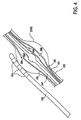
図3は、少なくとも1つの電極102を有するリード線であって、少なくとも1つの電極102がターゲットDRG上に位置するように患者の生体構造を通って前進させられたリード線100の実施形態を図解している。この例では、リード線100は、硬膜外に挿入され、脊髄Sに沿って順行方向に前進させられる。
図に示されるように、各DRGは、後根DRに沿って配置され、典型的には、少なくとも部分的に、茎(ペディクル:pedicle)PD間または孔内に存在する。各後根DRは、或る角度θで脊髄Sから出て来る。この角度θは、神経根スリーブの角度姿勢(アンギュレーション:angulation)と考えられ、患者によって、また脊柱に沿った位置によって、僅かに変化する。しかし、平均的な神経根アンギュレーションは、90度よりも著しく小さく、典型的には45度よりも小さい。
従って、この方法でのリード線100のターゲットDRGに向かっての進行は、角度θに沿って鋭い折り返し(ターン:turn)をなすことを伴うものとなる。この過酷な折り返しは、送給用具(ツール:tool)と、かかるリード線の配置に特有の設計上の特徴と、を利用することによって達成される。この設計上の特徴については、後の段落にてより詳しく説明する。更に、神経根,DRG及び周囲の組織構造の間の空間的な関係は、変性変化(degenerative change)、特に腰椎(lumber spine)の変性変化によって、大きな影響を受ける。このように、患者は、例えば、より難しい折り返しを必要とする、より小さいアンギュレーションを有するなど、通常の生体構造とは異なる神経根アンギュレーションを有することができる。前述の送給ツール及び装置は、これらの生体構造に適応するものである。
FIG. 3 illustrates an embodiment of a lead 100 having at least one
As shown in the figure, each DRG is disposed along the dorsal root DR and typically resides at least partially between the pedicle PDs or in the holes. Each dorsal root DR emerges from the spinal cord S at a certain angle θ. This angle θ is considered to be the angular posture of the nerve root sleeve (angulation) and varies slightly with the patient and with the position along the spinal column. However, the average nerve root angulation is significantly less than 90 degrees and typically less than 45 degrees.
Accordingly, the advancement of the
図4は、DRG上に位置したリード線100の実施形態の概略的な図解をもたらす図である。図に示されるように、DRGは、小型のソーマSM及び大型のソーマSM’を包含している。各ソーマは、連繋する軸索または神経根を通って伸長する神経繊維と接続されている。軸索または神経繊維は、神経細胞の、若しくはニューロンのセルボディから電気的な刺激を導くニューロンの、長くてほっそりした突起である。小型のソーマSMは小さい軸索AXを有し、大型のソーマSM’は大きい軸索AX’を有している。典型的には、軸索または神経繊維は、サイズに応じて電気的に補給される。
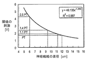
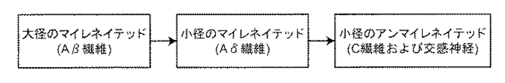
図5を参照すれば、閾値の刺激と神経繊維の直径との例示的な関係を図解するグラフが与えられている。一般に、神経繊維の直径が大きくなるに連れて、閾値の刺激は小さくなっている。従って、図6に示されるように、大径のマイレネイテッド(mylenated)繊維(Aβ繊維)は、小径のアンマイレネイテッド(unmylenated)繊維(C繊維)より前に補給される小径のマイレネイテッド繊維(Aδ繊維)より更に前に補給される。
FIG. 4 is a diagram that provides a schematic illustration of an embodiment of a lead 100 positioned on a DRG. As shown in the figure, the DRG includes a small soma SM and a large soma SM ′. Each soma is connected to nerve fibers that extend through the connected axons or nerve roots. Axons or nerve fibers are long, slender processes of neurons that conduct electrical stimulation from the cell body of neurons or neurons. The small soma SM has a small axon AX, and the large soma SM ′ has a large axon AX ′. Typically, axons or nerve fibers are replenished electrically depending on size.
Referring to FIG. 5, a graph illustrating an exemplary relationship between threshold stimulation and nerve fiber diameter is provided. Generally, as the nerve fiber diameter increases, the threshold stimulus decreases. Accordingly, as shown in FIG. 6, the large-diameter mylenated fiber (Aβ fiber) is replenished before the small-diameter unmylenated fiber (C fiber). Replenished before the fibers (Aδ fibers).
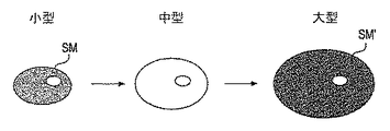
図7を参照すれば、神経繊維と対比して、セルボディについて反対のことが言える。一般に、より小さいセルボディ又はソーマ膜(メンブレイン:membrane)を補給または調節するのに、大きいものよりも電流が少なくて済む。従って、図8に示されるように、範囲Aに(セルボディSM’,SMに)弱い刺激が与えられているときには、直径がより大きいセルボディSM’よりも前に、直径がより小さいセルボディSMが、選択的に刺激を受けることになる。これは、より小さいセルボディの膜機能を効率良く調節するのに、比較的少ない電荷で済むことによるものである。
しかしながら、範囲Bに(軸索AX’,AXに)弱い刺激が与えられると、より小さい軸索AXよりも前に、より大きい軸索AX’が刺激を受ける。図4に戻って参照すれば、セルボディ又はソーマはDRG内に位置しているので、範囲Aは大略DRGに押す透視、範囲Bは大略後根DRに相当している。
Referring to FIG. 7, the opposite is true for cell bodies as opposed to nerve fibers. In general, less current is required to replenish or adjust a smaller cell body or soma membrane than a larger one. Therefore, as shown in FIG. 8, when a weak stimulus is applied to the range A (cell bodies SM ′ and SM), the cell body SM having a smaller diameter is preceded by the cell body SM ′ having a larger diameter. You will be selectively stimulated. This is due to the relatively small charge required to efficiently adjust the membrane function of the smaller cell body.
However, if a weak stimulus is applied to the range B (to the axons AX ′ and AX), the larger axon AX ′ is stimulated before the smaller axon AX. Referring back to FIG. 4, since the cell body or soma is located in the DRG, the range A roughly corresponds to the fluoroscopy that pushes the DRG, and the range B generally corresponds to the rear root DR.
患者が痛みを経験するとき、侵害または疼痛性の刺激は、直径が小さい,薄く髄鞘を有する、また、髄鞘のない、求心性の神経繊維または軸索AXを介して、末梢組織から中心の神経系へ変換される。電気的には、これらの繊維は、選択的にターゲットにするのがより難しい、というのは、直径がより大きい繊維または軸索AX’は、上述のサイズ原理に基づいて電流により優先的に活性化されるからである。これらより大きい繊維AX’は、例えば、軽い接触,圧力および振動など、また同様に、例えばSCSによって生み出される錯感覚と組み合わされる。 When a patient experiences pain, nociceptive or painful stimuli are centered from peripheral tissues via centripetal nerve fibers or axons AX that are small in diameter, thin and have a myelin sheath, and no myelin sheath Converted into the nervous system. Electrically, these fibers are more difficult to selectively target, because larger diameter fibers or axons AX ′ are preferentially more active by current based on the size principle described above. It is because it becomes. These larger fibers AX 'are combined, for example, with light touch, pressure and vibration, etc., as well as with the illusion produced by eg SCS.
本発明は、直径がより大きい軸索/より大きいソーマニューロンに対して、直径がより小さい軸索/より小さいソーマニューロンを、優先的に神経調節するための方法および装置を与えるものである。このことは、錯感覚を最小限に止め或いは無くする一方で、痛覚の伝達を遮る。
再び図4に戻って参照すれば、DRGを選択的に刺激する一方、例えば後根DRの部分など、他の生体構造の望ましくない刺激は最小限に止めるか排除するために、少なくとも1つの電極102が配置されるように、位置決めされたリード線100の例が図解されている。このことは、直径がより小さい軸索/より小さいソーマニューロンが、直径がより大きい軸索/より大きいソーマニューロンに先駆けて、補給されることができるようにする。
その結果として、痛感の伝達に関与するこれらのニューロンは、錯感覚を生み出すことなく調節されることができる。このことは、低電流または低電力の刺激、つまり錯感覚に対する閾値レベルでの刺激、を用いて達成される。この優先的な、ターゲットにされた神経調節の効果は、結果として生じる錯感覚を伴わない痛感消失である。更に、低電力の刺激は、低電力消費およびより長い電池寿命を意味している。
The present invention provides a method and apparatus for preferentially neuromodulating smaller diameter axons / smaller soma neurons relative to larger diameter axons / larger soma neurons. This blocks pain transmission while minimizing or eliminating illusion.
Referring back to FIG. 4, at least one electrode is used to selectively stimulate DRG while minimizing or eliminating unwanted stimulation of other anatomy, such as part of the dorsal root DR. An example of a lead 100 positioned so that 102 is positioned is illustrated. This allows smaller diameter axons / smaller soma neurons to be replenished ahead of larger diameter axons / larger soma neurons.
As a result, these neurons involved in pain transmission can be regulated without creating an illusion. This is accomplished using low current or low power stimuli, i.e. stimuli at threshold levels for the illusion. This preferential, targeted neuromodulatory effect is the resulting loss of pain without the illusion of illusion. Furthermore, low power stimulation means low power consumption and longer battery life.
従来の脊髄刺激システムは、典型的には、約30−120Hzの周波数を用いて刺激を与えるものである。それにひきかえ、ここに記載された装置および方法を用いて、従来の刺激システムで用いられているよりも低い刺激周波数で、治療的な利点が達成された。或る態様においては、ここに記載されたDRG刺激法に用いられる刺激周波数は、25Hzよりも低い。別の態様においては、刺激周波数は、例えば15Hz以下の範囲など、更に低くすることができる。更に別の態様においては、刺激周波数は10Hzよりも低い。或る特別な実施形態では、刺激周波数は5Hzである。今一つの特別な実施形態では、刺激周波数は2Hzである。
刺激周波数を低くすることに加えて、本発明の装置および方法のための他の刺激パターンは、従来の刺激システムで用いられていたものよりも低い。例えば、本発明の実施形態は、500マイクロアンペアよりも小さい振幅,120マイクロ秒よりも小さいパルス幅、及び先に議論したような低い刺激周波数を有する刺激信号を用いて、再現性のある皮節(dermatome)の特定の疼痛緩和を達成した。本発明の実施形態は、60マイクロ秒から120マイクロ秒までの範囲内で選択されたパルス幅を有する信号を用いて、皮節の特定の疼痛緩和を達成することができると信じられている。また、本発明の実施形態は、約200マイクロアンペア振幅を有する信号を用いて、皮節の特定の疼痛緩和を達成することができると信じられている。或る特定の例では、成人女性において、200マイクロアンペア振幅,60マイクロ秒のパルス幅および2Hzの周波数を有する信号を用いて、再現性のある皮節の特定の疼痛緩和が達成された。
あらゆる目的のために、引用することによりここに組み込まれるものであるが、例えば、2009年10月27日に出願された、「病状に対する選択的な刺激システム及び信号パラメータ」と題する米国特許出願第12/607,009号において提供されるものなど、他の好適な刺激信号パラメータを一緒に用いることができることも、理解されてもよい。
Conventional spinal cord stimulation systems typically provide stimulation using a frequency of about 30-120 Hz. In contrast, using the devices and methods described herein, therapeutic benefits were achieved at lower stimulation frequencies than used in conventional stimulation systems. In certain aspects, the stimulation frequency used in the DRG stimulation methods described herein is lower than 25 Hz. In another aspect, the stimulation frequency can be further reduced, such as in the range of 15 Hz or less. In yet another aspect, the stimulation frequency is lower than 10 Hz. In one particular embodiment, the stimulation frequency is 5 Hz. In another special embodiment, the stimulation frequency is 2 Hz.
In addition to lowering the stimulation frequency, other stimulation patterns for the devices and methods of the present invention are lower than those used in conventional stimulation systems. For example, embodiments of the present invention use reproducible dermatomes with stimulation signals having amplitudes less than 500 microamps, pulse widths less than 120 microseconds, and low stimulation frequencies as discussed above. (Dermatome) specific pain relief was achieved. It is believed that embodiments of the present invention can achieve specific pain relief of the dermis using a signal having a pulse width selected within the range of 60 microseconds to 120 microseconds. It is also believed that embodiments of the present invention can achieve specific pain relief in the dermis using signals having an amplitude of about 200 microamps. In one particular example, reproducible specific pain relief of the dermatome was achieved in an adult female using a signal having a 200 microamp amplitude, a pulse width of 60 microseconds, and a frequency of 2 Hz.
For all purposes, incorporated herein by reference, for example, U.S. patent application filed Oct. 27, 2009 entitled "Selective Stimulation System and Signal Parameters for Disease Conditions". It may also be appreciated that other suitable stimulation signal parameters can be used together, such as those provided in 12 / 607,009.
ニューロン細胞,非ニューロン細胞に加えて、例えば神経膠細胞(グリア細胞:glial cell)などがDRG内に在る。グリア細胞は、ニューロンを取り囲み、それらを定位置に保持し、栄養素を与え、恒常性の維持を助け、電気絶縁性をもたらし、病原菌を殺し、ニューロン修復および死んだニューロンの除去を制御し、また、神経系における信号の伝達に関与する。更に、グリア細胞は、神経系の創成を導く助けとなり、また、ニューロンの化学的環境およびイオン環境を制御する。グリア細胞は、また、慢性の疼痛状態での機能不全の増進および維持において一定の役割を果たす。例えば、衛星細胞やシュワン細胞(Schwann cell)など、様々な特定のタイプのグリア細胞がDRG内に見出される。 In addition to neuronal cells and non-neuronal cells, for example, glial cells are present in the DRG. Glial cells surround neurons, hold them in place, provide nutrients, help maintain homeostasis, provide electrical insulation, kill pathogens, control neuronal repair and removal of dead neurons, and Involved in the transmission of signals in the nervous system. In addition, glial cells help guide the creation of the nervous system and control the chemical and ionic environments of neurons. Glial cells also play a role in promoting and maintaining dysfunction in chronic pain states. For example, various specific types of glial cells are found in the DRG, such as satellite cells and Schwann cells.
衛星細胞は、DRG内でニューロン・セルボディを取り囲む。衛星細胞は、周囲のニューロンに栄養素を供給するとともに、ある種の構造的機能も有している。衛星細胞は、また、保護的な緩衝作用のある細胞として働く。更に、衛星細胞は、DRG内でニューロンと共に細隙結合(gap junction)を形成することができる。神経系における旧知の化学的な伝達とは対照的に、細胞間の細隙結合は直接の電気的結合をもたらす。このことは、次に、擬似的なグリア・ニューロン合胞体(glial-neuronal syncytium)の形態を創成することができる。
病態生理学的状態は、疼痛に関するニューロンの変換情報が機能不全になることができるように、グリアとセルボディとの間の関係を変化させることができる。従って、DRGの神経刺激(neurostimulation)は、ニューロンに対して直接に影響を及ぼすだけではなく、グリア細胞の機能にも影響を与えることができる。神経刺激を用いたグリア細胞の機能の調節は、次に、ニューロンの機能性を変化させることができる。かかる調節は、錯感覚の感覚を生じさせる閾値以下のレベルで起こり得る。
The satellite cells surround the neuron cell body within the DRG. Satellite cells supply nutrients to surrounding neurons and have some structural function. Satellite cells also act as protective buffering cells. Furthermore, satellite cells can form gap junctions with neurons in the DRG. In contrast to the old-fashioned chemical transmission in the nervous system, the interstitial joints between cells result in direct electrical connections. This in turn can create a pseudo-glial-neuronal syncytium morphology.
The pathophysiological state can change the relationship between glia and cell bodies so that neuronal conversion information about pain can become dysfunctional. Thus, DRG neurostimulation not only directly affects neurons, but can also affect glial cell function. Modulation of glial function using neural stimulation can then alter neuronal functionality. Such adjustment can occur at a sub-threshold level that creates an illusionary sensation.
図9は、DRG上に位置決めされたリード線100の実施形態の概略的な図解をもたらす図である。図に示されるように、DRGは、小型のソーマSM及び大型のソーマSM‘を取り囲む衛星細胞SCを包含している。幾つかの実施形態では、少なくとも1つの電極102によって与えられる刺激エネルギーは、衛星細胞SCを神経調節する。かかる神経調節(neuromodulation)は、その機能に影響を及ぼし、2次的には、例えば疼痛などの知覚情報の処理を妨げ或いは変化させるために、連繋するニューロンの機能にも影響を及ぼす。その結果、DRG衛星細胞の神経調節は、慢性の疼痛に対する治療となり得る。
FIG. 9 is a diagram that provides a schematic illustration of an embodiment of a lead 100 positioned on a DRG. As shown in the figure, the DRG includes a satellite cell SC surrounding a small soma SM and a large soma SM '. In some embodiments, the stimulation energy provided by the at least one
今一つのタイプのグリア細胞は、シュワン細胞(Schwann cell)である。ニューロ・レンモサイト(neurolemnocyte)とも呼ばれるシュワン細胞は、ニューロンの生存を助けるものである。髄鞘の有る軸策(myelinated axon)において、シュワン細胞は髄鞘(ミリエン鞘:myelin sheath)を形成する。脊椎動物の神経系は、絶縁のための、また、軸策における膜の静電容量を低減する方法として、髄鞘に依存する。シュワン細胞の配置は、伝導の速度を大幅に高めエネルギーを節約する跳躍伝導を可能にする。髄鞘の無いシュワン細胞は、軸策の維持に関与している。シュワン細胞は、また、DRG内のニューロンに対して、軸策の支持,栄養作用および別の支持作用をもたらす。 Another type of glial cell is the Schwann cell. Schwann cells, also called neurolemnocytes, help the survival of neurons. In a myelinated axon, Schwann cells form a myelin sheath. The vertebrate nervous system relies on the myelin sheath as a means of insulation and as a way to reduce membrane capacitance in axons. Schwann cell placement allows jumping conduction that greatly increases the speed of conduction and saves energy. Schwann cells without myelin are involved in maintaining axon. Schwann cells also provide axon support, trophic and other support for neurons in the DRG.
再び図9を参照すれば、DRG内のニューロンの軸策に沿ってシュワン細胞SWCが図解されている。幾つかの実施形態では、リード線100の少なくとも1つの電極102によって与えられた刺激エネルギーは、シュワン細胞SWCを神経調節する。かかる神経調節は、シュワン細胞の機能に影響を及ぼし、2次的には、連繋するニューロンの機能にも影響を及ぼす。シュワン細胞の神経調節は、ニューロンの処理,疼痛を含む知覚情報の変換(transduction)及び伝達に影響を及ぼす。このように、DRG刺激は、シュワン細胞の機能に影響を及ぼすことにより、短期間および長期間にわたって疼痛を緩和する。このことは、また、錯感覚の感覚を生じさせる閾値以下の刺激レベルで達成されることができる。
Referring again to FIG. 9, a Schwann cell SWC is illustrated along the axons of neurons in the DRG. In some embodiments, the stimulation energy provided by the at least one
DRG内に存在する神経系の細胞(ニューロン,グリア等)のかなた、DRG内および周囲に移動して、DRGをカプセルに包み、この代謝的に非常に活性な神経系組織に血液供給および酸素を与える、血管の密接なネットワークがある。図9は、DRGに連繋した血管BV及びDRGを概略的に図解している。幾つかの実施形態では、リード線100の少なくとも1つの電極102によって刺激エネルギーが与えられる。
DRGの刺激は、ニューロン,グリア及び/又は血管から、疼痛を含む知覚情報の変換および処理に関与するニューロンの機能に対して最終的に影響を及ぼす、様々の作用物質(エイジェント:agent)の放出を生じさせることができる。例えば、幾つかの実施形態では、DRGの刺激は、1つ若しくはそれ以上のタイプのニューロン或いは1つ若しくはそれ以上のタイプのグリア細胞に、少なくとも1つの血管に影響を及ぼす血管作用性物質を放出させる。前記少なくとも1つの血管は、次に、疼痛を処理するに際して、ニューロンの機能に影響を及ぼすニューロン作用性の物質を放出する。或いは、前記少なくとも1つの血管は、疼痛を処理するに際して、間接的にニューロンの機能に影響を及ぼすグリア活性物質を放出する。
別の実施形態では、DRGの刺激は、ニューロン細胞の信号伝達に対する導管もしくはグリア細胞の信号伝達に対する導管をもたらす、連繋する血管に直接に作用する。かかる細胞信号伝達は、最終的には、例えば、新陳代謝率を変えることにより、或いは、ひいては細胞機能を直接に変化させる神経反応性化学物質の放出を誘導することにより、ニューロンの機能に影響を及ぼす。細胞機能の変化は、短期,中期および長期にわたって痛覚消失もしくは疼痛緩和を誘導する。かかる変化は、錯感覚の感覚を生じせしめる閾値以下の刺激レベルで起こり得る。
Beyond the nervous system cells (neurons, glia, etc.) present in the DRG, move into and around the DRG, encapsulate the DRG, supply blood and oxygen to this metabolically highly active nervous tissue There is a close network of blood vessels that give. FIG. 9 schematically illustrates blood vessels BV and DRG connected to the DRG. In some embodiments, stimulation energy is provided by at least one
DRG stimulation releases various agents from neurons, glia and / or blood vessels that ultimately affect the function of neurons involved in the conversion and processing of sensory information, including pain Can be generated. For example, in some embodiments, stimulation of DRG releases vasoactive substances that affect at least one blood vessel to one or more types of neurons or one or more types of glial cells. Let The at least one blood vessel then releases neuron-acting substances that affect neuronal function in treating pain. Alternatively, the at least one blood vessel releases a glial active substance that indirectly affects the function of neurons in treating pain.
In another embodiment, the stimulation of DRG acts directly on connected blood vessels that provide a conduit for neuronal cell signaling or a conduit for glial cell signaling. Such cellular signaling ultimately affects neuronal function, for example, by changing the metabolic rate or, in turn, by inducing the release of neuroreactive chemicals that directly alter cell function. . Changes in cell function induce analgesia or pain relief over the short, medium and long term. Such changes can occur at sub-threshold stimulation levels that create an illusionary sensation.
例えばDRGなど、ターゲットにした生体構造近辺へのリード線100の所望の位置決めは、様々の送給システム,装置および方法を用いて達成することができる。図3に戻って参照すれば、かかる位置決めの例が図解されている。この例では、リード線100は、硬膜外に挿入され、脊髄Sに沿って順行方向に進行させられる。
図に示されるように、各DRGは、後根DRに沿って配置され、典型的には、少なくとも部分的に、茎(ペディクル:pedicle)PD間または孔内に存在する。各後根DRは、或る角度θで脊髄Sから出て来る。この角度θは、神経根スリーブの角度姿勢(アンギュレーション:angulation)と考えられ、患者によって、また脊柱に沿った位置によって、僅かに変化する。しかし、平均的な神経根アンギュレーションは、90度よりも著しく小さく、典型的には45度よりも小さい。
従って、この方法でのリード線100のターゲットDRGに向かっての進行は、角度θに沿って鋭い折り返し(ターン:turn)をなすことを伴うものとなる。更に、神経根,DRG及び周囲の組織構造の間の空間的な関係は、変性変化(degenerative change)、特に腰椎(lumber spine)の変性変化によって、大きな影響を受ける。このように、患者は、例えば、より難しい折り返しを必要とする、より小さいアンギュレーションを有するなど、通常の生体構造とは異なる神経根アンギュレーションを有することができる。この過酷な折り返しは、かかるリード線の配置に特有の設計上の特徴を有する送給用具を用いることによって達成される。
Desired positioning of the
As shown in the figure, each DRG is disposed along the dorsal root DR and typically resides at least partially between the pedicle PDs or in the holes. Each dorsal root DR emerges from the spinal cord S at a certain angle θ. This angle θ is considered to be the angular posture of the nerve root sleeve (angulation) and varies slightly with the patient and with the position along the spinal column. However, the average nerve root angulation is significantly less than 90 degrees and typically less than 45 degrees.
Accordingly, the advancement of the
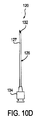
図10A〜10Dを参照すれば、ターゲットDRGにアクセスためのリード線および送給装置の例が図解されている。図10Aは、それ自体に配置された4つの電極102を備えた遠位端部101を有する軸部103を備えたリード線100の実施形態を図解するものである。1,2,3,4,5,6,7,8若しくはそれ以上を含む任意の数の電極102が存在してもよいことが、理解されよう。この実施形態では、遠位端部101は、終端が閉じられた遠位先端部106を有している。この遠位先端部106は、2,3例を挙げると、例えば(図に示されている)球形などの丸形、或いは涙の形および円錐形を含む様々な形状を有することができる。これらの形状は、他の目的を果たすと同様に、リード線100に傷付けない先端部をもたらすものである。リード線100には、終端が閉じられた遠位先端部106に向かって延びる探り針内腔部104が在る。送給システム120は、また、鞘状の覆い122(図10B),探り針124(図10C)及び導入ニードル126(図10D)を含めて、図解されている。
Referring to FIGS. 10A-10D, examples of leads and feeders for accessing a target DRG are illustrated. FIG. 10A illustrates an embodiment of a lead 100 with a
図10Bを参照すれば、鞘状の覆い(シース:sheath)122の実施形態が図解されている。この実施形態では、シース122は、角度αを有するように予め湾曲させられた遠位端部128を有している。ここに、角度αは約80度から165度の範囲内にある。シース122は、図11に示されるように、その遠位端部128の一部がリード線100の遠位先端部106に当接するまで、リード線100の軸部103を覆って前進させられるように、寸法設定されて構成されている。このように、この実施形態の球状先端部106は、シース122がそれを越えて伸長することも防止している。リード線100を覆うシース122の通路は、シース122の予備的な湾曲に従ってリード線100に曲げを生じさせる。このように、シース122は、脊髄Sに沿って、また、例えば横向きなど、ターゲットDRGに向かって、リード線100を操縦する際に助けとなる。
Referring to FIG. 10B, an embodiment of a
図10Cに戻って参照すれば、探り針124の実施形態が図解されている。探り針124は、曲率半径が略0.1〜0.5の範囲内にあるように予め湾曲させられている遠位端部130を有している。この探り針124は、リード線100の探り針内腔104内で前進させられるように、寸法設定されて構成されている。典型的には、探り針124は、その遠位端部130がリード線100の遠位端部101と整列するように、伸長している。リード線100を通る探り針124の通路は、探り針124の予備的な湾曲に従ってリード線100に曲げを生じさせる。典型的には、探り針124は、シース122よりも小さい曲率半径つまりより過酷な曲がりを有している。
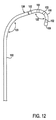
従って、図12に示されるように、探り針124がリード線100内に配置されている場合、シース122を通るリード線100及び探り針124の延長部は、リード線100を第1湾曲部123を通って曲げ、若しくは指向させる。更に、シース122の遠位端部128を越えるリード線100及び探り針124の延長部は、リード線100が第2湾曲部125に沿って更に曲がることを許容する。このことは、横方向に指向したリード線100が、神経根の角度姿勢に沿ってターゲットDRGに向かって湾曲することを許容する。この2段階の湾曲は、少なくとも1つの電極102がターゲットDRG上に,その付近に或いはその周囲に、特に、角度θに沿った鋭い折り返しをなすことにより、リード線100が首尾良く位置決めされることを許容する。
Referring back to FIG. 10C, an embodiment of the
Accordingly, as shown in FIG. 12, when the
このように、リード線100は、それ自体、トルクが加わることはなく、また、操縦されることもないので、高剛性あるいは高トルク耐性の構造を有する必要はない。リード線100は、2段階の湾曲を介して当該リード線100を指向させるシース122と探り針124とを用いて位置決めされる。このことは、オペレータが、複合的に手を用いて、リード線100に、また、随意的にはシース122にトルクを加える必要を無くする。このことは、また、リード線100が、非常に軟質でフレキシブルであるだけでなく目立たない構造を有することも可能にする。このことは、ひいては、一旦リード線100が植え込まれると、例えばターゲットDRG及び/又は神経根などの神経組織を加圧することによって生み出される不快や腐食を最小限に止める。例えば、このような軟質でフレキシブルなリード線100は、本体の挙動(例えば、湾曲,伸張,捩り)によってリード線100に伝えられた力の大きさを最小限に止めることであろう。
Thus, the
図10Dに戻って参照すれば、導入ニードル(introducing needle)126の実施形態が図解されている。導入ニードル126は、脊髄Sの硬膜上腔(epidural space)へのアクセスのために用いられる。ニードル126は、中空の軸部127を有し、また、典型的にはごく僅かに湾曲した遠位端部132を有している。軸部127は、リード線100,シース122及び探り針124の通過を許容するように寸法設定されている。幾つかの実施形態では、ニードル126は、硬膜上腔内に従来の経皮的なリード線を配置するのに用いられる硬膜外ニードルのサイズと一致した14番ゲージ(gauge)のものである。しかしながら、他のサイズの針、特に16〜18番ゲージのものなどより小さい針も、用いることができることが理解されよう。同様に、施術者に知られている様々な先端部や、特定の用途のために設計された特別注文の先端部も、用いることができることが理解されよう。ニードル126は、また、典型的には、その近位端部の付近に、ルアーロック(Luer-Lok:登録商標)接続具134を備えている。ルアーロック接続具134は、タブ付きのハブ(tabbed hub)を有する雌型の接続具で、例えば注射器(シリンジ:syringe)などの雄型接続具のスリーブ内のネジ部に係合するものである。
Referring back to FIG. 10D, an embodiment of an introducing
あらゆる目的のために、引用することによりここに組み込まれるものであるが、2009年1月14日に出願された米国特許出願第611144,690号に、かかる送給システム120を用いてターゲットDRGにアプローチする方法が、本発明と共に用いるのに適用可能な他の送給システム,装置および方法と一緒に、更に説明され図解されている。
For all purposes, incorporated herein by reference, US Pat. No. 6,114,144, filed Jan. 14, 2009, uses such a
錯感覚に対する刺激閾値を与えるために、他のタイプのリード線および相当する送給システムが、かかるリード線を所望の方位に位置決めするのに用いることができる、ことが理解されよう。例えば、リード線は、予め湾曲させられた形状を有していてもよく、当該リード線は、真っ直ぐな形状、例えば実質的に真っ直ぐな形状、或いはリード線よりも大きい曲率半径を有する湾曲した形状など、を有するシースを通って送給可能である。シースからのリード線の前進は、リード線が、その予め湾曲させられた形状に向かって、反動することを許容する。リード線とシースとの間での様々な湾曲の組み合わせは、1次的および2次的な湾曲の多様性を許容する。リード線が一旦望ましく配置されると、シースは除去されてもよい。 It will be appreciated that other types of leads and corresponding delivery systems can be used to position such leads in a desired orientation to provide a stimulus threshold for the illusion. For example, the lead may have a pre-curved shape, the lead being a straight shape, such as a substantially straight shape, or a curved shape having a larger radius of curvature than the lead wire. And so on. Advancement of the lead from the sheath allows the lead to recoil towards its pre-curved shape. The combination of various curves between the lead and the sheath allows for a variety of primary and secondary curves. Once the lead is desirably placed, the sheath may be removed.
DRGへの様々なアプローチを用いることができることも理解されよう。2,3の例を挙げれば、順行性硬膜外アプローチ,逆行性硬膜外アプローチ,トランスフォーラメナル(transforamenal)アプローチ,エクストラフォーラミナル(extraforaminal)アプローチ(脊柱の外側から末梢神経に沿ったアプローチ)及び対側(contralateral)アプローチなどである。同様に、前記少なくとも1つの電極は、DRGの中,上または周囲、DRGに近接して,付近に,または近辺に、位置決めされてもよい。 It will also be appreciated that various approaches to DRG can be used. A few examples include antegrade epidural approach, retrograde epidural approach, transforamenal approach, extraforaminal approach (from outside the spinal column along the peripheral nerve Approaches) and contralateral approaches. Similarly, the at least one electrode may be positioned in, on or around the DRG, close to, near or near the DRG.
前述の発明は、理解の明瞭化の目的で、図および例を用いて多少詳しく説明されてきたが、様々の変更,修正および均等物を用いることができることは明白であり、また、上述の説明は、添付の請求の範囲によって規定される本発明の範囲を制限するものと解されるべきではない。 Although the foregoing invention has been described in some detail by way of illustration and example for purposes of clarity of understanding, it will be apparent that various changes, modifications and equivalents may be used and the foregoing description. Should not be construed as limiting the scope of the invention which is defined by the appended claims.
Claims (34)
少なくとも1つの電極を有するリード線であって、後根神経節に近接して配置されるように構成されたリード線と、
実質的な錯感覚の感覚を生じせしめることなく疼痛感覚に作用するように、前記後根神経節を刺激するために、前記リード線が前記後根神経節に近接して位置決めされている間、前記少なくとも1つの電極の少なくとも1つに刺激エネルギーを供給するように構成された、パルス発生器と、
を備えている、ことを特徴とするシステム。 A system for treating patient pain comprising:
A lead having at least one electrode, the lead configured to be disposed proximate to the dorsal root ganglion;
While the lead is positioned proximate to the dorsal root ganglion to stimulate the dorsal root ganglion to act on pain sensation without causing a substantial sensory sensation, A pulse generator configured to supply stimulation energy to at least one of the at least one electrode;
A system characterized by comprising:
少なくとも1つの電極を有するリード線を位置決めするステップであって、前記少なくとも1つの電極の少なくとも1つが、後根神経節に近接するように位置決めするステップと、
前記後根神経節の少なくとも一部を刺激するために、前記少なくとも1つの電極の少なくとも1つに刺激エネルギーを供給するステップと、を備え、
前記リード線の位置決めステップと前記刺激エネルギーの供給ステップとが合わさって、実質的な錯感覚の感覚を生じせしめることなく疼痛感覚に作用する、
ことを特徴とする方法。 A method for treating pain in a patient comprising:
Positioning a lead having at least one electrode, wherein at least one of said at least one electrode is positioned proximate to a dorsal root ganglion;
Providing stimulation energy to at least one of the at least one electrode to stimulate at least a portion of the dorsal root ganglion;
The lead wire positioning step and the stimulation energy supply step combine to act on pain sensation without causing a substantial illusion of illusion.
A method characterized by that.
患者による疼痛の感覚に関連した後根神経節を特定するステップと、
患者による疼痛の感覚を低減するために、前記後根神経節内の少なくとも1つのグリア細胞を神経調節するステップと、
を備えている、ことを特徴とする方法。 A method for treating a patient, comprising:
Identifying a dorsal root ganglion associated with the pain sensation by the patient;
Neuromodulating at least one glial cell in the dorsal root ganglion to reduce pain sensation by the patient;
A method characterized by comprising:
少なくとも1つの電極を有するリード線を位置決めするステップであって、前記少なくとも1つの電極の少なくとも1つが、後根神経節に近接するように位置決めするステップと、
少なくとも1つの血管が後根神経節内のニューロンを細胞調節する作用物質を放出せしめるように、前記後根神経節に連繋した前記少なくとも1つの血管を刺激するように、前記少なくとも1つの電極に刺激エネルギーを供給するステップと、
を備える、ことを特徴とする方法。 A method for treating a patient, comprising:
Positioning a lead having at least one electrode, wherein at least one of said at least one electrode is positioned proximate to a dorsal root ganglion;
Stimulate the at least one electrode to stimulate the at least one blood vessel connected to the dorsal root ganglion such that at least one blood vessel releases an agent that regulates neurons in the dorsal root ganglion Supplying energy,
A method characterized by comprising:
Applications Claiming Priority (3)
| Application Number | Priority Date | Filing Date | Title |
|---|---|---|---|
| US16300709P | 2009-03-24 | 2009-03-24 | |
| US61/163,007 | 2009-03-24 | ||
| PCT/US2010/028450 WO2010111358A2 (en) | 2009-03-24 | 2010-03-24 | Pain management with stimulation subthreshold to parasthesia |
Related Child Applications (1)
| Application Number | Title | Priority Date | Filing Date |
|---|---|---|---|
| JP2015079445A Division JP6018249B2 (en) | 2009-03-24 | 2015-04-08 | Management of pain with subthreshold stimuli for illusion |
Publications (2)
| Publication Number | Publication Date |
|---|---|
| JP2012521801A true JP2012521801A (en) | 2012-09-20 |
| JP2012521801A5 JP2012521801A5 (en) | 2014-09-18 |
Family
ID=42781839
Family Applications (2)
| Application Number | Title | Priority Date | Filing Date |
|---|---|---|---|
| JP2012502199A Pending JP2012521801A (en) | 2009-03-24 | 2010-03-24 | Management of pain with subthreshold stimuli for illusion |
| JP2015079445A Active JP6018249B2 (en) | 2009-03-24 | 2015-04-08 | Management of pain with subthreshold stimuli for illusion |
Family Applications After (1)
| Application Number | Title | Priority Date | Filing Date |
|---|---|---|---|
| JP2015079445A Active JP6018249B2 (en) | 2009-03-24 | 2015-04-08 | Management of pain with subthreshold stimuli for illusion |
Country Status (7)
| Country | Link |
|---|---|
| US (3) | US8380318B2 (en) |
| EP (1) | EP2411091A4 (en) |
| JP (2) | JP2012521801A (en) |
| CN (1) | CN102438698B (en) |
| AU (1) | AU2010229985B2 (en) |
| CA (1) | CA2758459A1 (en) |
| WO (1) | WO2010111358A2 (en) |
Families Citing this family (155)
| Publication number | Priority date | Publication date | Assignee | Title |
|---|---|---|---|---|
| US7450993B2 (en) | 2004-09-08 | 2008-11-11 | Spinal Modulation, Inc. | Methods for selective stimulation of a ganglion |
| US9205261B2 (en) | 2004-09-08 | 2015-12-08 | The Board Of Trustees Of The Leland Stanford Junior University | Neurostimulation methods and systems |
| US20120277839A1 (en) | 2004-09-08 | 2012-11-01 | Kramer Jeffery M | Selective stimulation to modulate the sympathetic nervous system |
| US20090093403A1 (en) | 2007-03-01 | 2009-04-09 | Feng Zhang | Systems, methods and compositions for optical stimulation of target cells |
| US9278159B2 (en) * | 2005-07-22 | 2016-03-08 | The Board Of Trustees Of The Leland Stanford Junior University | Light-activated cation channel and uses thereof |
| US10052497B2 (en) * | 2005-07-22 | 2018-08-21 | The Board Of Trustees Of The Leland Stanford Junior University | System for optical stimulation of target cells |
| US9274099B2 (en) | 2005-07-22 | 2016-03-01 | The Board Of Trustees Of The Leland Stanford Junior University | Screening test drugs to identify their effects on cell membrane voltage-gated ion channel |
| US9238150B2 (en) | 2005-07-22 | 2016-01-19 | The Board Of Trustees Of The Leland Stanford Junior University | Optical tissue interface method and apparatus for stimulating cells |
| US8926959B2 (en) * | 2005-07-22 | 2015-01-06 | The Board Of Trustees Of The Leland Stanford Junior University | System for optical stimulation of target cells |
| US20070073354A1 (en) | 2005-09-26 | 2007-03-29 | Knudson Mark B | Neural blocking therapy |
| AU2007329252A1 (en) | 2006-12-06 | 2008-06-12 | Spinal Modulation, Inc. | Hard tissue anchors and delivery devices |
| WO2008070809A2 (en) | 2006-12-06 | 2008-06-12 | Spinal Modulation, Inc. | Implantable flexible circuit leads and methods of use |
| WO2008070808A2 (en) * | 2006-12-06 | 2008-06-12 | Spinal Modulation, Inc. | Expandable stimulation leads and methods of use |
| EP2091594B1 (en) | 2006-12-06 | 2018-06-06 | Spinal Modulation Inc. | Delivery devices for stimulating nerve tissue on multiple spinal levels |
| WO2008086470A1 (en) | 2007-01-10 | 2008-07-17 | The Board Of Trustees Of The Leland Stanford Junior University | System for optical stimulation of target cells |
| US8401609B2 (en) | 2007-02-14 | 2013-03-19 | The Board Of Trustees Of The Leland Stanford Junior University | System, method and applications involving identification of biological circuits such as neurological characteristics |
| US11679261B2 (en) | 2007-03-09 | 2023-06-20 | Mainstay Medical Limited | Systems and methods for enhancing function of spine stabilization muscles associated with a spine surgery intervention |
| US9072897B2 (en) | 2007-03-09 | 2015-07-07 | Mainstay Medical Limited | Systems and methods for restoring muscle function to the lumbar spine |
| EP2125100B1 (en) | 2007-03-09 | 2021-08-25 | Mainstay Medical Limited | Muscle stimulator |
| US11679262B2 (en) | 2007-03-09 | 2023-06-20 | Mainstay Medical Limited | Systems and methods for restoring muscle function to the lumbar spine |
| US11331488B2 (en) | 2007-03-09 | 2022-05-17 | Mainstay Medical Limited | Systems and methods for enhancing function of spine stabilization muscles associated with a spine surgery intervention |
| US10925637B2 (en) * | 2010-03-11 | 2021-02-23 | Mainstay Medical Limited | Methods of implanting electrode leads for use with implantable neuromuscular electrical stimulator |
| US10035027B2 (en) * | 2007-10-31 | 2018-07-31 | The Board Of Trustees Of The Leland Stanford Junior University | Device and method for ultrasonic neuromodulation via stereotactic frame based technique |
| US10434327B2 (en) | 2007-10-31 | 2019-10-08 | The Board Of Trustees Of The Leland Stanford Junior University | Implantable optical stimulators |
| US20090204173A1 (en) | 2007-11-05 | 2009-08-13 | Zi-Ping Fang | Multi-Frequency Neural Treatments and Associated Systems and Methods |
| CA2722278C (en) | 2008-04-23 | 2020-03-31 | Feng Zhang | Systems, methods and compositions for optical stimulation of target cells |
| US7890182B2 (en) | 2008-05-15 | 2011-02-15 | Boston Scientific Neuromodulation Corporation | Current steering for an implantable stimulator device involving fractionalized stimulation pulses |
| MX2010012986A (en) | 2008-05-29 | 2011-05-25 | Univ Leland Stanford Junior | Cell line, system and method for optical control of secondary messengers. |
| CA2728238C (en) | 2008-06-17 | 2019-03-12 | M. Bret Schneider | Methods, systems and devices for optical stimulation of target cells using an optical transmission element |
| BRPI0915583A2 (en) * | 2008-06-17 | 2016-01-26 | Univ Leland Stanford Junior | apparatus and methods for controlling cell development |
| WO2010006049A1 (en) | 2008-07-08 | 2010-01-14 | The Board Of Trustees Of The Leland Stanford Junior University | Materials and approaches for optical stimulation of the peripheral nervous system |
| CN102202729B (en) | 2008-10-27 | 2014-11-05 | 脊髓调制公司 | Selective stimulation systems and signal parameters for medical conditions |
| US9327121B2 (en) | 2011-09-08 | 2016-05-03 | Nevro Corporation | Selective high frequency spinal cord modulation for inhibiting pain, including cephalic and/or total body pain with reduced side effects, and associated systems and methods |
| US8255057B2 (en) | 2009-01-29 | 2012-08-28 | Nevro Corporation | Systems and methods for producing asynchronous neural responses to treat pain and/or other patient conditions |
| NZ602416A (en) | 2008-11-14 | 2014-08-29 | Univ Leland Stanford Junior | Optically-based stimulation of target cells and modifications thereto |
| CN102438698B (en) | 2009-03-24 | 2014-09-10 | 脊髓调制公司 | Pain management with stimulation subthreshold to parasthesia |
| WO2010124128A1 (en) | 2009-04-22 | 2010-10-28 | Nevro Corporation | Spinal cord modulation for inducing paresthetic and anesthetic effects, and associated systems and methods |
| EP2243510B1 (en) | 2009-04-22 | 2014-04-09 | Nevro Corporation | Sytems for selective high frequency spinal cord modulation for inhibiting pain with reduced side effects |
| US8498710B2 (en) | 2009-07-28 | 2013-07-30 | Nevro Corporation | Linked area parameter adjustment for spinal cord stimulation and associated systems and methods |
| US9327110B2 (en) | 2009-10-27 | 2016-05-03 | St. Jude Medical Luxembourg Holdings SMI S.A.R.L. (“SJM LUX SMI”) | Devices, systems and methods for the targeted treatment of movement disorders |
| CN103079633B (en) | 2010-03-11 | 2016-05-04 | 梅恩斯塔伊医疗公司 | Be used for the treatment of modular stimulator, implanted RF ablation system and the using method of backache |
| US9950159B2 (en) | 2013-10-23 | 2018-04-24 | Mainstay Medical Limited | Systems and methods for restoring muscle function to the lumbar spine and kits for implanting the same |
| US11786725B2 (en) | 2012-06-13 | 2023-10-17 | Mainstay Medical Limited | Systems and methods for restoring muscle function to the lumbar spine and kits for implanting the same |
| US11684774B2 (en) | 2010-03-11 | 2023-06-27 | Mainstay Medical Limited | Electrical stimulator for treatment of back pain and methods of use |
| US9999763B2 (en) | 2012-06-13 | 2018-06-19 | Mainstay Medical Limited | Apparatus and methods for anchoring electrode leads adjacent to nervous tissue |
| SG183899A1 (en) | 2010-03-17 | 2012-10-30 | Univ Leland Stanford Junior | Light-sensitive ion-passing molecules |
| AU2011250941A1 (en) | 2010-05-10 | 2012-11-29 | Spinal Modulation, Inc. | Methods, systems and devices for reducing migration |
| US10086012B2 (en) | 2010-11-05 | 2018-10-02 | The Board Of Trustees Of The Leland Stanford Junior University | Control and characterization of memory function |
| CN106106368A (en) | 2010-11-05 | 2016-11-16 | 斯坦福大学托管董事会 | Optically-controlledCNS CNS dysfunction |
| EP3225108A1 (en) | 2010-11-05 | 2017-10-04 | The Board of Trustees of The Leland Stanford Junior University | Optogenetic control of reward-related behaviors |
| ES2684307T3 (en) | 2010-11-05 | 2018-10-02 | The Board Of Trustees Of The Leland Stanford Junior University | Stabilized opsin-type proteins of staggered function and methods of use thereof |
| CN106422081B (en) | 2010-11-05 | 2019-06-21 | 斯坦福大学托管董事会 | The upper conversion of light for light genetic method |
| EP3486253A1 (en) | 2010-11-05 | 2019-05-22 | The Board of Trustees of The Leland Stanford Junior University | Light-activated chimeric opsins and methods of using the same |
| US8696722B2 (en) | 2010-11-22 | 2014-04-15 | The Board Of Trustees Of The Leland Stanford Junior University | Optogenetic magnetic resonance imaging |
| US8649874B2 (en) | 2010-11-30 | 2014-02-11 | Nevro Corporation | Extended pain relief via high frequency spinal cord modulation, and associated systems and methods |
| AU2011336467A1 (en) | 2010-12-01 | 2013-07-04 | Spinal Modulation, Inc. | Agent delivery systems for selective neuromodulation |
| US9649494B2 (en) | 2011-04-29 | 2017-05-16 | Medtronic, Inc. | Electrical stimulation therapy based on head position |
| US10448889B2 (en) | 2011-04-29 | 2019-10-22 | Medtronic, Inc. | Determining nerve location relative to electrodes |
| US9789307B2 (en) | 2011-04-29 | 2017-10-17 | Medtronic, Inc. | Dual prophylactic and abortive electrical stimulation |
| CN103889502B (en) | 2011-08-02 | 2016-02-24 | 梅恩斯塔伊医疗公司 | For the equipment of the electrode guiding piece that grappling uses together with implantable neuromuscular electric stimulation therapy device |
| CA2859364C (en) | 2011-12-16 | 2019-05-07 | The Board Of Trustees Of The Leland Stanford Junior University | Opsin polypeptides and methods of use thereof |
| US20150018728A1 (en) | 2012-01-26 | 2015-01-15 | Bluewind Medical Ltd. | Wireless neurostimulators |
| CA2865296A1 (en) | 2012-02-21 | 2013-08-29 | Karl A. DEISSEROTH | Compositions and methods for treating neurogenic disorders of the pelvic floor |
| US8676331B2 (en) | 2012-04-02 | 2014-03-18 | Nevro Corporation | Devices for controlling spinal cord modulation for inhibiting pain, and associated systems and methods, including controllers for automated parameter selection |
| US8718790B2 (en) | 2012-05-25 | 2014-05-06 | Boston Scientific Neuromodulation Corporation | Systems and methods for providing electrical stimulation of multiple dorsal root ganglia with a single lead |
| EP2854935A1 (en) | 2012-05-25 | 2015-04-08 | Boston Scientific Neuromodulation Corporation | Systems and methods for electrically stimulating patient tissue on or around one or more bony structures |
| WO2013177307A1 (en) | 2012-05-25 | 2013-11-28 | Boston Scientific Neuromodulation Corporation | Percutaneous implantation of an electrical stimulation lead for stimulating dorsal root ganglion |
| US9919148B2 (en) * | 2012-05-25 | 2018-03-20 | Boston Scientific Neuromodulation Corporation | Distally curved electrical stimulation lead and methods of making and using |
| US9186501B2 (en) | 2012-06-13 | 2015-11-17 | Mainstay Medical Limited | Systems and methods for implanting electrode leads for use with implantable neuromuscular electrical stimulator |
| US10195419B2 (en) | 2012-06-13 | 2019-02-05 | Mainstay Medical Limited | Electrode leads for use with implantable neuromuscular electrical stimulator |
| US9833614B1 (en) | 2012-06-22 | 2017-12-05 | Nevro Corp. | Autonomic nervous system control via high frequency spinal cord modulation, and associated systems and methods |
| EP2866888B1 (en) | 2012-06-30 | 2018-11-07 | Boston Scientific Neuromodulation Corporation | System for compounding low-frequency sources for high-frequency neuromodulation |
| US9002459B2 (en) | 2012-09-19 | 2015-04-07 | Boston Scientific Neuromodulation Corporation | Method for selectively modulating neural elements in the dorsal horn |
| WO2014087337A1 (en) | 2012-12-06 | 2014-06-12 | Bluewind Medical Ltd. | Delivery of implantable neurostimulators |
| WO2014130865A2 (en) | 2013-02-22 | 2014-08-28 | Boston Scientific Neuromodulation Corporation | Neurostimulation system having increased flexibility for creating complex pulse trains |
| US8909344B2 (en) | 2013-03-07 | 2014-12-09 | Jeffrey Edward Arle | Head worn brain stimulation device and method |
| US9174053B2 (en) | 2013-03-08 | 2015-11-03 | Boston Scientific Neuromodulation Corporation | Neuromodulation using modulated pulse train |
| EP3583979B1 (en) * | 2013-03-15 | 2021-04-28 | Boston Scientific Neuromodulation Corporation | Systems for delivering subthreshold therapy to a patient |
| US9636380B2 (en) | 2013-03-15 | 2017-05-02 | The Board Of Trustees Of The Leland Stanford Junior University | Optogenetic control of inputs to the ventral tegmental area |
| EP2968997B1 (en) | 2013-03-15 | 2019-06-26 | The Board of Trustees of the Leland Stanford Junior University | Optogenetic control of behavioral state |
| WO2014179331A2 (en) | 2013-04-29 | 2014-11-06 | The Board Of Trustees Of The Leland Stanford Junior University | Devices, systems and methods for optogenetic modulation of action potentials in target cells |
| US9180297B2 (en) | 2013-05-16 | 2015-11-10 | Boston Scientific Neuromodulation Corporation | System and method for spinal cord modulation to treat motor disorder without paresthesia |
| US9950173B2 (en) | 2013-06-06 | 2018-04-24 | Boston Scientific Neuromodulation Corporation | System and method for delivering sub-threshold and super-threshold therapy to a patient |
| US10029102B2 (en) | 2013-06-06 | 2018-07-24 | Boston Scientific Neuromodulation Corporation | System and method for delivering modulated sub-threshold therapy to a patient |
| US9895539B1 (en) | 2013-06-10 | 2018-02-20 | Nevro Corp. | Methods and systems for disease treatment using electrical stimulation |
| US9623250B2 (en) | 2013-06-28 | 2017-04-18 | Boston Scientific Neuromodulation Corporation | Electrode selection for sub-threshold modulation therapy |
| CN105407964B (en) | 2013-07-26 | 2018-05-04 | 波士顿科学神经调制公司 | The system that modulation therapy and unaware are provided |
| WO2015023782A1 (en) | 2013-08-14 | 2015-02-19 | The Board Of Trustees Of The Leland Stanford Junior University | Compositions and methods for controlling pain |
| US10086201B2 (en) | 2013-10-09 | 2018-10-02 | GiMer Medical Co., Ltd. | Electronic stimulation device, method of treatment and electronic stimulation system |
| TWM498025U (en) | 2014-10-01 | 2015-04-01 | Gimer Medical Co Ltd | High-frequency electric stimulator for dorsal root ganglia |
| US10639476B2 (en) | 2013-10-09 | 2020-05-05 | GiMer Medical Co., Ltd. | Electronic stimulation device, method of treatment and electronic stimulation system |
| US10183165B2 (en) | 2013-10-09 | 2019-01-22 | GiMer Medical Co., Ltd. | Method of reducing renal hypertension and computer-readable medium |
| US10632310B2 (en) | 2013-10-09 | 2020-04-28 | GiMer Medical Co., Ltd. | Electronic stimulation device, method of treatment and electronic stimulation system |
| US9956408B2 (en) | 2013-10-09 | 2018-05-01 | Gimer Medical Co. Ltd. | Method for reducing spasticity and non-transitory computer-readable medium thereof |
| US10086197B2 (en) | 2013-10-09 | 2018-10-02 | GiMer Medical Co., Ltd. | Method for reducing overactive bladder syndrome and computer-readable medium thereof |
| US9358396B2 (en) | 2013-11-01 | 2016-06-07 | Boston Scientific Neuromodulation Corporation | Systems and methods for delivering sub-threshold therapy to a patient at a physiological midline |
| US10149978B1 (en) | 2013-11-07 | 2018-12-11 | Nevro Corp. | Spinal cord modulation for inhibiting pain via short pulse width waveforms, and associated systems and methods |
| US10010715B2 (en) | 2013-12-04 | 2018-07-03 | Boston Scientific Neuromodulation Corporation | Systems and methods for delivering therapy to the dorsal horn of a patient |
| CA2937081A1 (en) | 2014-02-05 | 2015-08-13 | Boston Scientific Neuromodulation Corporation | System and method for delivering modulated sub-threshold therapy to a patient |
| US9381359B2 (en) | 2014-02-05 | 2016-07-05 | Boston Scientific Neuromodulation Corporation | System and method for delivering modulated sub-threshold therapy to a patient |
| AU2015264561B2 (en) | 2014-05-20 | 2020-02-20 | Nevro Corporation | Implanted pulse generators with reduced power consumption via signal strength/duration characteristics, and associated systems and methods |
| CA2954855C (en) | 2014-07-24 | 2020-08-18 | Boston Scientific Neuromodulation Corporation | Enhanced dorsal horn stimulation using multiple electrical fields |
| JP6437638B2 (en) | 2014-09-23 | 2018-12-12 | ボストン サイエンティフィック ニューロモデュレイション コーポレイション | System for calibrating dorsal horn stimuli |
| EP3197542A1 (en) | 2014-09-23 | 2017-08-02 | Boston Scientific Neuromodulation Corporation | Neuromodulation specific to objective function of modulation field for targeted tissue |
| CN106714901A (en) | 2014-09-23 | 2017-05-24 | 波士顿科学神经调制公司 | Perception calibration of neural tissue using field troll |
| AU2015321576B2 (en) | 2014-09-23 | 2018-11-08 | Boston Scientific Neuromodulation Corporation | Systems and methods for receiving user-provided selection of electrode lists |
| US9814880B2 (en) | 2014-09-23 | 2017-11-14 | Boston Scientific Neuromodulation Corporation | Short pulse width stimulation |
| US9993646B2 (en) | 2014-09-23 | 2018-06-12 | Boston Scientific Neuromodulation Corporation | Sub-perception modulation responsive to patient input |
| JP6580678B2 (en) | 2014-09-23 | 2019-09-25 | ボストン サイエンティフィック ニューロモデュレイション コーポレイション | Neuromodulation using burst stimulation |
| US10471268B2 (en) | 2014-10-16 | 2019-11-12 | Mainstay Medical Limited | Systems and methods for monitoring muscle rehabilitation |
| US9597521B2 (en) | 2015-01-21 | 2017-03-21 | Bluewind Medical Ltd. | Transmitting coils for neurostimulation |
| US10004896B2 (en) | 2015-01-21 | 2018-06-26 | Bluewind Medical Ltd. | Anchors and implant devices |
| US9764146B2 (en) | 2015-01-21 | 2017-09-19 | Bluewind Medical Ltd. | Extracorporeal implant controllers |
| US9962547B2 (en) | 2015-02-05 | 2018-05-08 | Stimgenics, Llc | Method and apparatus for multimodal electrical modulation of pain |
| WO2016130454A1 (en) * | 2015-02-09 | 2016-08-18 | Boston Scientific Neuromodulation Corporation | System for determining neurological position of epidural leads |
| AU2016235457B2 (en) | 2015-03-20 | 2021-01-07 | Medtronic Sg, Llc | Method and apparatus for multimodal electrical modulation of pain |
| US10850102B2 (en) | 2015-03-20 | 2020-12-01 | Medtronic Sg, Llc | Method and apparatus for multimodal electrical modulation of pain |
| US11167139B2 (en) | 2015-03-20 | 2021-11-09 | Medtronic Sg, Llc | Method and apparatus for multi modal electrical modulation of pain using composite electromagnetic fields |
| EP3291880B1 (en) | 2015-05-05 | 2021-07-07 | Haralambidis, Cosmo | Device for electrical stimulation of peridontal complex and surrounding tissue |
| US11103696B2 (en) | 2015-05-05 | 2021-08-31 | Cosmo Haralambidis | Device for electrical stimulation of peridontal complex and surrounding tissue |
| CN107921261B (en) | 2015-05-28 | 2022-01-14 | 波士顿科学神经调制公司 | Neuromodulation using randomly adjusted stimulation parameters |
| US9782589B2 (en) | 2015-06-10 | 2017-10-10 | Bluewind Medical Ltd. | Implantable electrostimulator for improving blood flow |
| US10568516B2 (en) | 2015-06-22 | 2020-02-25 | The Board Of Trustees Of The Leland Stanford Junior University | Methods and devices for imaging and/or optogenetic control of light-responsive neurons |
| US11318310B1 (en) | 2015-10-26 | 2022-05-03 | Nevro Corp. | Neuromodulation for altering autonomic functions, and associated systems and methods |
| US10105540B2 (en) | 2015-11-09 | 2018-10-23 | Bluewind Medical Ltd. | Optimization of application of current |
| US9713707B2 (en) | 2015-11-12 | 2017-07-25 | Bluewind Medical Ltd. | Inhibition of implant migration |
| EP3389768B1 (en) * | 2015-12-18 | 2023-03-01 | Medtronic, Inc. | High duty cycle electrical stimulation therapy |
| US20170209699A1 (en) | 2016-01-25 | 2017-07-27 | Nevro Corp. | Treatment of congestive heart failure with electrical stimulation, and associated systems and methods |
| US10799701B2 (en) | 2016-03-30 | 2020-10-13 | Nevro Corp. | Systems and methods for identifying and treating patients with high-frequency electrical signals |
| US20180303704A1 (en) | 2016-04-08 | 2018-10-25 | Vibrating Therapeutic Apparel, Llc | Vibrating therapeutic apparel |
| WO2017201058A1 (en) | 2016-05-17 | 2017-11-23 | Boston Scientific Neuromodulation Corporation | Systems and methods for anchoring a lead for neurostimulation of a target anatomy |
| US11446504B1 (en) | 2016-05-27 | 2022-09-20 | Nevro Corp. | High frequency electromagnetic stimulation for modulating cells, including spontaneously active and quiescent cells, and associated systems and methods |
| US10327810B2 (en) | 2016-07-05 | 2019-06-25 | Mainstay Medical Limited | Systems and methods for enhanced implantation of electrode leads between tissue layers |
| WO2018039117A1 (en) | 2016-08-22 | 2018-03-01 | Boston Scientific Neuromodulation Corporation | Neuromodulation system for providing paresthesia and analgesia and a system with leads and with electrodes |
| US10525268B2 (en) | 2016-08-23 | 2020-01-07 | Medtronic, Inc. | Delivery of independent interleaved programs to produce higher-frequency electrical stimulation therapy |
| WO2018039670A1 (en) * | 2016-08-26 | 2018-03-01 | Spr Therapeutics, Llc | Devices and methods for delivery of electrical current for pain relief |
| US10716935B2 (en) | 2016-11-04 | 2020-07-21 | Boston Scientific Neuromodulation Corporation | Electrical stimulation leads, systems and methods for stimulation of dorsal root ganglia |
| US10124178B2 (en) | 2016-11-23 | 2018-11-13 | Bluewind Medical Ltd. | Implant and delivery tool therefor |
| CN110121375B (en) * | 2016-12-23 | 2024-02-02 | 洛桑联邦理工学院 | Sensory information compliant spinal cord stimulation system for motor function recovery |
| US10709886B2 (en) | 2017-02-28 | 2020-07-14 | Boston Scientific Neuromodulation Corporation | Electrical stimulation leads and systems with elongate anchoring elements and methods of making and using |
| US10835739B2 (en) | 2017-03-24 | 2020-11-17 | Boston Scientific Neuromodulation Corporation | Electrical stimulation leads and systems with elongate anchoring elements and methods of making and using |
| US11294165B2 (en) | 2017-03-30 | 2022-04-05 | The Board Of Trustees Of The Leland Stanford Junior University | Modular, electro-optical device for increasing the imaging field of view using time-sequential capture |
| US20180353764A1 (en) | 2017-06-13 | 2018-12-13 | Bluewind Medical Ltd. | Antenna configuration |
| JP7279048B2 (en) | 2017-12-13 | 2023-05-22 | ニューロス・メディカル・インコーポレイティッド | Nerve cuff deployment device |
| CR20200357A (en) | 2018-01-30 | 2021-03-29 | Nevro Corp | Efficient use of an implantable pulse generator battery, and associated systems and methods |
| KR102505594B1 (en) | 2018-04-09 | 2023-03-06 | 뉴로스 메디컬 인코포레이티드 | Apparatus and method for setting capacitance |
| JP2020089723A (en) * | 2018-12-07 | 2020-06-11 | アヴェント インコーポレイテッド | Device and method for selectively and reversibly modulating nervous system structure to inhibit perception of pain |
| AU2020207940A1 (en) | 2019-01-17 | 2021-08-12 | Nevro Corp. | Sensory threshold and/or adaptation for neurological therapy screening and/or parameter selection, and associated systems and methods |
| US11590352B2 (en) | 2019-01-29 | 2023-02-28 | Nevro Corp. | Ramped therapeutic signals for modulating inhibitory interneurons, and associated systems and methods |
| US11918811B2 (en) | 2019-05-06 | 2024-03-05 | Medtronic Sg, Llc | Method and apparatus for multi modal or multiplexed electrical modulation of pain using composite electromagnetic fields |
| US11452874B2 (en) | 2020-02-03 | 2022-09-27 | Medtronic, Inc. | Shape control for electrical stimulation therapy |
| EP4103267A4 (en) | 2020-02-11 | 2024-02-28 | Neuros Medical Inc | System and method for quantifying qualitative patient-reported data sets |
| US11554264B2 (en) | 2020-04-24 | 2023-01-17 | Medtronic, Inc. | Electrode position detection |
| US11400299B1 (en) | 2021-09-14 | 2022-08-02 | Rainbow Medical Ltd. | Flexible antenna for stimulator |
| US20230218900A1 (en) * | 2022-01-12 | 2023-07-13 | Advanced Neuromodulation Systems, Inc. | Closed loop systems and methods for managing pain of a patient |
Citations (3)
| Publication number | Priority date | Publication date | Assignee | Title |
|---|---|---|---|---|
| WO2008070807A2 (en) * | 2006-12-06 | 2008-06-12 | Spinal Modulation, Inc. | Delivery devices, systems and methods for stimulating nerve tissue on multiple spinal levels |
| WO2008070804A2 (en) * | 2006-12-06 | 2008-06-12 | Spinal Modulation, Inc. | Grouped leads for spinal stimulation |
| WO2009134350A2 (en) * | 2008-04-29 | 2009-11-05 | Cardiac Pacemakers, Inc. | Systems for selectively stimulating nerve roots |
Family Cites Families (248)
| Publication number | Priority date | Publication date | Assignee | Title |
|---|---|---|---|---|
| US525891A (en) | 1894-09-11 | Fastener for electric wires | ||
| US3724467A (en) | 1971-04-23 | 1973-04-03 | Avery Labor Inc | Electrode implant for the neuro-stimulation of the spinal cord |
| US3845770A (en) | 1972-06-05 | 1974-11-05 | Alza Corp | Osmatic dispensing device for releasing beneficial agent |
| US3916899A (en) | 1973-04-25 | 1975-11-04 | Alza Corp | Osmotic dispensing device with maximum and minimum sizes for the passageway |
| US4232679A (en) | 1977-01-26 | 1980-11-11 | Pacesetter Systems, Inc. | Programmable human tissue stimulator |
| US4141367A (en) | 1977-04-29 | 1979-02-27 | Med Telectronics Ltd. | Cardiac electrode/pacer system analyzer |
| US4374527A (en) | 1978-07-19 | 1983-02-22 | Medtronic, Inc. | Body stimulation lead |
| US4313448A (en) | 1980-01-28 | 1982-02-02 | Medtronic, Inc. | Myocardial sutureless lead |
| US4298003A (en) | 1980-05-12 | 1981-11-03 | Alza Corporation | System for delivering agent at zero order rate with emerging agent below saturation |
| US4414986A (en) | 1982-01-29 | 1983-11-15 | Medtronic, Inc. | Biomedical stimulation lead |
| US4479491A (en) | 1982-07-26 | 1984-10-30 | Martin Felix M | Intervertebral stabilization implant |
| US4549556A (en) | 1982-12-08 | 1985-10-29 | Cordis Corporation | Implantable lead |
| US4739764A (en) | 1984-05-18 | 1988-04-26 | The Regents Of The University Of California | Method for stimulating pelvic floor muscles for regulating pelvic viscera |
| US4607639A (en) | 1984-05-18 | 1986-08-26 | Regents Of The University Of California | Method and system for controlling bladder evacuation |
| US4590946A (en) | 1984-06-14 | 1986-05-27 | Biomed Concepts, Inc. | Surgically implantable electrode for nerve bundles |
| US4573481A (en) | 1984-06-25 | 1986-03-04 | Huntington Institute Of Applied Research | Implantable electrode array |
| US4640286A (en) | 1984-11-02 | 1987-02-03 | Staodynamics, Inc. | Optimized nerve fiber stimulation |
| US4577642A (en) | 1985-02-27 | 1986-03-25 | Medtronic, Inc. | Drug dispensing body implantable lead employing molecular sieves and methods of fabrication |
| US4786155A (en) | 1986-12-16 | 1988-11-22 | Fantone Stephen D | Operating microscope providing an image of an obscured object |
| US4920979A (en) | 1988-10-12 | 1990-05-01 | Huntington Medical Research Institute | Bidirectional helical electrode for nerve stimulation |
| US4945912A (en) | 1988-11-25 | 1990-08-07 | Sensor Electronics, Inc. | Catheter with radiofrequency heating applicator |
| US4940065A (en) | 1989-01-23 | 1990-07-10 | Regents Of The University Of California | Surgically implantable peripheral nerve electrode |
| US4950270A (en) | 1989-02-03 | 1990-08-21 | Boehringer Mannheim Corporation | Cannulated self-tapping bone screw |
| US4976711A (en) | 1989-04-13 | 1990-12-11 | Everest Medical Corporation | Ablation catheter with selectively deployable electrodes |
| DE3918431C1 (en) | 1989-06-06 | 1990-07-26 | B. Braun Melsungen Ag, 3508 Melsungen, De | |
| JPH03193393A (en) | 1989-12-22 | 1991-08-23 | Dainippon Printing Co Ltd | Thermal mimeograph paper |
| US5299569A (en) | 1991-05-03 | 1994-04-05 | Cyberonics, Inc. | Treatment of neuropsychiatric disorders by nerve stimulation |
| US5358514A (en) | 1991-12-18 | 1994-10-25 | Alfred E. Mann Foundation For Scientific Research | Implantable microdevice with self-attaching electrodes |
| US20010006967A1 (en) | 1992-09-21 | 2001-07-05 | Stanley M. Crain | Method of simultaneously enhancing analgesic potency and attenuating adverse side effects caused by tramadol and other bimodally-acting opioid agonists |
| US5360441A (en) | 1992-10-30 | 1994-11-01 | Medtronic, Inc. | Lead with stylet capture member |
| GB9302335D0 (en) * | 1993-02-05 | 1993-03-24 | Macdonald Alexander J R | Electrotherapeutic apparatus |
| US5792187A (en) | 1993-02-22 | 1998-08-11 | Angeion Corporation | Neuro-stimulation to control pain during cardioversion defibrillation |
| US5344438A (en) | 1993-04-16 | 1994-09-06 | Medtronic, Inc. | Cuff electrode |
| US5411540A (en) | 1993-06-03 | 1995-05-02 | Massachusetts Institute Of Technology | Method and apparatus for preferential neuron stimulation |
| US5417719A (en) | 1993-08-25 | 1995-05-23 | Medtronic, Inc. | Method of using a spinal cord stimulation lead |
| US5400784A (en) | 1993-10-15 | 1995-03-28 | Case Western Reserve University | Slowly penetrating inter-fascicular nerve cuff electrode and method of using |
| US5584835A (en) | 1993-10-18 | 1996-12-17 | Greenfield; Jon B. | Soft tissue to bone fixation device and method |
| US5411537A (en) | 1993-10-29 | 1995-05-02 | Intermedics, Inc. | Rechargeable biomedical battery powered devices with recharging and control system therefor |
| US5458626A (en) | 1993-12-27 | 1995-10-17 | Krause; Horst E. | Method of electrical nerve stimulation for acceleration of tissue healing |
| US5419763B1 (en) | 1994-01-04 | 1997-07-15 | Cor Trak Medical Inc | Prostatic drug-delivery catheter |
| US5501703A (en) | 1994-01-24 | 1996-03-26 | Medtronic, Inc. | Multichannel apparatus for epidural spinal cord stimulator |
| US5489294A (en) | 1994-02-01 | 1996-02-06 | Medtronic, Inc. | Steroid eluting stitch-in chronic cardiac lead |
| SE9401267D0 (en) | 1994-04-14 | 1994-04-14 | Siemens Elema Ab | The electrode device |
| US5505201A (en) | 1994-04-20 | 1996-04-09 | Case Western Reserve University | Implantable helical spiral cuff electrode |
| US5514175A (en) | 1994-11-09 | 1996-05-07 | Cerebral Stimulation, Inc. | Auricular electrical stimulator |
| US5741319A (en) | 1995-01-27 | 1998-04-21 | Medtronic, Inc. | Biocompatible medical lead |
| US5733322A (en) | 1995-05-23 | 1998-03-31 | Medtronic, Inc. | Positive fixation percutaneous epidural neurostimulation lead |
| US5755750A (en) | 1995-11-13 | 1998-05-26 | University Of Florida | Method and apparatus for selectively inhibiting activity in nerve fibers |
| SE9504334D0 (en) | 1995-12-04 | 1995-12-04 | Pacesetter Ab | Guidewire assembly |
| FR2742058B1 (en) | 1995-12-12 | 1998-03-06 | Ela Medical Sa | FOLDABLE ANCHOR BARS PROBES FOR AN IMPLANTED MEDICAL DEVICE, IN PARTICULAR FOR A HEART STIMULATOR |
| WO1997029802A2 (en) | 1996-02-20 | 1997-08-21 | Advanced Bionics Corporation | Improved implantable microstimulator and systems employing the same |
| US5713922A (en) | 1996-04-25 | 1998-02-03 | Medtronic, Inc. | Techniques for adjusting the locus of excitation of neural tissue in the spinal cord or brain |
| US5702429A (en) | 1996-04-04 | 1997-12-30 | Medtronic, Inc. | Neural stimulation techniques with feedback |
| US5824021A (en) | 1996-04-25 | 1998-10-20 | Medtronic Inc. | Method and apparatus for providing feedback to spinal cord stimulation for angina |
| US5711316A (en) | 1996-04-30 | 1998-01-27 | Medtronic, Inc. | Method of treating movement disorders by brain infusion |
| US5938690A (en) | 1996-06-07 | 1999-08-17 | Advanced Neuromodulation Systems, Inc. | Pain management system and method |
| US5983141A (en) | 1996-06-27 | 1999-11-09 | Radionics, Inc. | Method and apparatus for altering neural tissue function |
| US5885290A (en) | 1996-12-09 | 1999-03-23 | Guerrero; Cesar A. | Intra-oral bone distraction device |
| DE29703043U1 (en) | 1997-02-20 | 1997-04-24 | Signus Medizintechnik Gmbh | Spinal implant |
| US5957965A (en) | 1997-03-03 | 1999-09-28 | Medtronic, Inc. | Sacral medical electrical lead |
| US6785576B2 (en) | 1997-04-21 | 2004-08-31 | Medtronic, Inc. | Medical electrical lead |
| US5865843A (en) | 1997-04-23 | 1999-02-02 | Medtronic Inc. | Medical neurological lead with integral fixation mechanism |
| US5948007A (en) | 1997-04-30 | 1999-09-07 | Medtronic, Inc. | Dual channel implantation neurostimulation techniques |
| US6161048A (en) | 1997-06-26 | 2000-12-12 | Radionics, Inc. | Method and system for neural tissue modification |
| US6839588B1 (en) | 1997-07-31 | 2005-01-04 | Case Western Reserve University | Electrophysiological cardiac mapping system based on a non-contact non-expandable miniature multi-electrode catheter and method therefor |
| US5871531A (en) | 1997-09-25 | 1999-02-16 | Medtronic, Inc. | Medical electrical lead having tapered spiral fixation |
| US5984896A (en) | 1997-10-28 | 1999-11-16 | Ojp #73, Inc. | Fixated catheter |
| US6415187B1 (en) | 1998-02-10 | 2002-07-02 | Advanced Bionics Corporation | Implantable, expandable, multicontact electrodes and insertion needle for use therewith |
| US6045532A (en) | 1998-02-20 | 2000-04-04 | Arthrocare Corporation | Systems and methods for electrosurgical treatment of tissue in the brain and spinal cord |
| US6493588B1 (en) | 1998-03-18 | 2002-12-10 | Mmc/Gatx Partnership No. 1 | Electro-nerve stimulator systems and methods |
| US6314325B1 (en) | 1998-04-07 | 2001-11-06 | William R. Fitz | Nerve hyperpolarization method and apparatus for pain relief |
| US6319241B1 (en) | 1998-04-30 | 2001-11-20 | Medtronic, Inc. | Techniques for positioning therapy delivery elements within a spinal cord or a brain |
| US6161047A (en) | 1998-04-30 | 2000-12-12 | Medtronic Inc. | Apparatus and method for expanding a stimulation lead body in situ |
| US6421566B1 (en) | 1998-04-30 | 2002-07-16 | Medtronic, Inc. | Selective dorsal column stimulation in SCS, using conditioning pulses |
| US6120467A (en) | 1998-04-30 | 2000-09-19 | Medtronic Inc. | Spinal cord simulation systems with patient activity monitoring and therapy adjustments |
| US6002964A (en) | 1998-07-15 | 1999-12-14 | Feler; Claudio A. | Epidural nerve root stimulation |
| WO2000006249A2 (en) | 1998-07-27 | 2000-02-10 | Case Western Reserve University | Method and apparatus for closed-loop stimulation of the hypoglossal nerve in human patients to treat obstructive sleep apnea |
| US7599736B2 (en) | 2001-07-23 | 2009-10-06 | Dilorenzo Biomedical, Llc | Method and apparatus for neuromodulation and physiologic modulation for the treatment of metabolic and neuropsychiatric disease |
| US6104957A (en) | 1998-08-21 | 2000-08-15 | Alo; Kenneth M. | Epidural nerve root stimulation with lead placement method |
| US6044297A (en) | 1998-09-25 | 2000-03-28 | Medtronic, Inc. | Posture and device orientation and calibration for implantable medical devices |
| US6611715B1 (en) | 1998-10-26 | 2003-08-26 | Birinder R. Boveja | Apparatus and method for neuromodulation therapy for obesity and compulsive eating disorders using an implantable lead-receiver and an external stimulator |
| US6356788B2 (en) | 1998-10-26 | 2002-03-12 | Birinder Bob Boveja | Apparatus and method for adjunct (add-on) therapy for depression, migraine, neuropsychiatric disorders, partial complex epilepsy, generalized epilepsy and involuntary movement disorders utilizing an external stimulator |
| US6208902B1 (en) | 1998-10-26 | 2001-03-27 | Birinder Bob Boveja | Apparatus and method for adjunct (add-on) therapy for pain syndromes utilizing an implantable lead and an external stimulator |
| US6366814B1 (en) | 1998-10-26 | 2002-04-02 | Birinder R. Boveja | External stimulator for adjunct (add-on) treatment for neurological, neuropsychiatric, and urological disorders |
| US6205359B1 (en) | 1998-10-26 | 2001-03-20 | Birinder Bob Boveja | Apparatus and method for adjunct (add-on) therapy of partial complex epilepsy, generalized epilepsy and involuntary movement disorders utilizing an external stimulator |
| WO2000033909A1 (en) | 1998-12-09 | 2000-06-15 | Cook Incorporated | Hollow, curved, superelastic medical needle |
| US6909917B2 (en) | 1999-01-07 | 2005-06-21 | Advanced Bionics Corporation | Implantable generator having current steering means |
| US6393325B1 (en) | 1999-01-07 | 2002-05-21 | Advanced Bionics Corporation | Directional programming for implantable electrode arrays |
| EP1158919B1 (en) | 1999-03-09 | 2005-06-29 | Thermage, Inc. | Apparatus for treatment of tissue |
| US6835194B2 (en) | 1999-03-18 | 2004-12-28 | Durect Corporation | Implantable devices and methods for treatment of pain by delivery of fentanyl and fentanyl congeners |
| US6436099B1 (en) | 1999-04-23 | 2002-08-20 | Sdgi Holdings, Inc. | Adjustable spinal tether |
| US6055456A (en) | 1999-04-29 | 2000-04-25 | Medtronic, Inc. | Single and multi-polar implantable lead for sacral nerve electrical stimulation |
| US6214016B1 (en) | 1999-04-29 | 2001-04-10 | Medtronic, Inc. | Medical instrument positioning device internal to a catheter or lead and method of use |
| US6353762B1 (en) | 1999-04-30 | 2002-03-05 | Medtronic, Inc. | Techniques for selective activation of neurons in the brain, spinal cord parenchyma or peripheral nerve |
| US6889094B1 (en) | 1999-05-14 | 2005-05-03 | Advanced Bionics Corporation | Electrode array for hybrid cochlear stimulator |
| US6832115B2 (en) | 2000-08-17 | 2004-12-14 | William N. Borkan | Catheter leads for the intrathecal space and method of use |
| US6516227B1 (en) | 1999-07-27 | 2003-02-04 | Advanced Bionics Corporation | Rechargeable spinal cord stimulator system |
| US6517542B1 (en) | 1999-08-04 | 2003-02-11 | The Cleveland Clinic Foundation | Bone anchoring system |
| US6298256B1 (en) | 1999-09-10 | 2001-10-02 | Frank-Egbert Meyer | Device and method for the location and catheterization of the surroundings of a nerve |
| US7047082B1 (en) | 1999-09-16 | 2006-05-16 | Micronet Medical, Inc. | Neurostimulating lead |
| US7949395B2 (en) | 1999-10-01 | 2011-05-24 | Boston Scientific Neuromodulation Corporation | Implantable microdevice with extended lead and remote electrode |
| US6605094B1 (en) | 1999-11-19 | 2003-08-12 | Advanced Bionics Corporation | Integrated subcutaneous tunneling and carrying tool |
| US6466821B1 (en) | 1999-12-08 | 2002-10-15 | Pacesetter, Inc. | AC/DC multi-axis accelerometer for determining patient activity and body position |
| CN2401143Y (en) | 1999-12-15 | 2000-10-18 | 杨俊� | Lumbar puncture cerebrospinal fluid pressure dynamic monitoring apparatus |
| US6356786B1 (en) | 2000-01-20 | 2002-03-12 | Electrocore Techniques, Llc | Method of treating palmar hyperhydrosis by electrical stimulation of the sympathetic nervous chain |
| US6438423B1 (en) | 2000-01-20 | 2002-08-20 | Electrocore Technique, Llc | Method of treating complex regional pain syndromes by electrical stimulation of the sympathetic nerve chain |
| US6885888B2 (en) | 2000-01-20 | 2005-04-26 | The Cleveland Clinic Foundation | Electrical stimulation of the sympathetic nerve chain |
| US7096070B1 (en) | 2000-02-09 | 2006-08-22 | Transneuronix, Inc. | Medical implant device for electrostimulation using discrete micro-electrodes |
| EP1257816A1 (en) | 2000-02-11 | 2002-11-20 | Yale University | Planar patch clamp electrodes |
| US6582441B1 (en) | 2000-02-24 | 2003-06-24 | Advanced Bionics Corporation | Surgical insertion tool |
| FR2809017B1 (en) | 2000-05-16 | 2002-08-09 | Ela Medical Sa | REQUIRED FOR PLACEMENT OF AN IMPLANTABLE HEART CAVITY PACING LEAD IN THE CORONARY NETWORK |
| US6748276B1 (en) | 2000-06-05 | 2004-06-08 | Advanced Neuromodulation Systems, Inc. | Neuromodulation therapy system |
| US7305268B2 (en) | 2000-07-13 | 2007-12-04 | Northstar Neurscience, Inc. | Systems and methods for automatically optimizing stimulus parameters and electrode configurations for neuro-stimulators |
| US6754539B1 (en) | 2000-08-10 | 2004-06-22 | Advanced Neuromodulation Systems, Inc. | Spinal cord stimulation lead with an anode guard |
| US6510347B2 (en) | 2000-08-17 | 2003-01-21 | William N. Borkan | Spinal cord stimulation leads |
| US6871099B1 (en) | 2000-08-18 | 2005-03-22 | Advanced Bionics Corporation | Fully implantable microstimulator for spinal cord stimulation as a therapy for chronic pain |
| US6862479B1 (en) | 2000-08-30 | 2005-03-01 | Advanced Bionics Corporation | Spinal cord stimulation as a therapy for sexual dysfunction |
| US6522926B1 (en) | 2000-09-27 | 2003-02-18 | Cvrx, Inc. | Devices and methods for cardiovascular reflex control |
| US6510348B2 (en) | 2000-12-20 | 2003-01-21 | Medtronic, Inc. | Perfusion lead and method of use |
| US6704604B2 (en) | 2000-12-28 | 2004-03-09 | Medtronic, Inc. | System and method for promoting selective tissue in-growth for an implantable medical device |
| US20020087113A1 (en) | 2000-12-29 | 2002-07-04 | Medtronic, Inc. | Drug management techniques for an implantable medical device |
| US6788975B1 (en) | 2001-01-30 | 2004-09-07 | Advanced Bionics Corporation | Fully implantable miniature neurostimulator for stimulation as a therapy for epilepsy |
| US6901287B2 (en) | 2001-02-09 | 2005-05-31 | Medtronic, Inc. | Implantable therapy delivery element adjustable anchor |
| US6873342B2 (en) | 2001-04-12 | 2005-03-29 | Mitsubishi Electric Research Laboratories, Inc. | Method for generating detail directed visibility elements for a graphics model |
| US6512958B1 (en) | 2001-04-26 | 2003-01-28 | Medtronic, Inc. | Percutaneous medical probe and flexible guide wire |
| US6892098B2 (en) | 2001-04-26 | 2005-05-10 | Biocontrol Medical Ltd. | Nerve stimulation for treating spasticity, tremor, muscle weakness, and other motor disorders |
| US6684105B2 (en) | 2001-08-31 | 2004-01-27 | Biocontrol Medical, Ltd. | Treatment of disorders by unidirectional nerve stimulation |
| US6928320B2 (en) | 2001-05-17 | 2005-08-09 | Medtronic, Inc. | Apparatus for blocking activation of tissue or conduction of action potentials while other tissue is being therapeutically activated |
| EP1395335A1 (en) | 2001-05-29 | 2004-03-10 | Medtronic, Inc. | Closed-loop neuromodulation for prevention and treatment of cardiac conditions |
| US6638276B2 (en) | 2001-06-06 | 2003-10-28 | Oratec Interventions, Inc. | Intervertebral disc device employing prebent sheath |
| DE10129490A1 (en) | 2001-06-21 | 2003-01-02 | Helmut Mueckter | Implantable screw for stabilization of joint or bone fracture, has flexible shaft which interconnects proximal head portion and distal insertion portion of elongated screw body |
| US6606521B2 (en) | 2001-07-09 | 2003-08-12 | Neuropace, Inc. | Implantable medical lead |
| US7011647B2 (en) | 2001-07-13 | 2006-03-14 | Scimed Life Systems, Inc. | Introducer sheath |
| US6554809B2 (en) | 2001-08-02 | 2003-04-29 | Teodulo Aves | Epidural catheter needle |
| US6535767B1 (en) | 2001-08-21 | 2003-03-18 | James W. Kronberg | Apparatus and method for bioelectric stimulation, healing acceleration and pain relief |
| US20030069569A1 (en) | 2001-08-29 | 2003-04-10 | Burdette Everette C. | Ultrasound device for treatment of intervertebral disc tissue |
| US6999819B2 (en) | 2001-08-31 | 2006-02-14 | Medtronic, Inc. | Implantable medical electrical stimulation lead fixation method and apparatus |
| WO2003026736A2 (en) | 2001-09-28 | 2003-04-03 | Northstar Neuroscience, Inc. | Methods and implantable apparatus for electrical therapy |
| US6934583B2 (en) | 2001-10-22 | 2005-08-23 | Pacesetter, Inc. | Implantable lead and method for stimulating the vagus nerve |
| US6745079B2 (en) | 2001-11-07 | 2004-06-01 | Medtronic, Inc. | Electrical tissue stimulation apparatus and method |
| US6849075B2 (en) | 2001-12-04 | 2005-02-01 | Estech, Inc. | Cardiac ablation devices and methods |
| US6864418B2 (en) | 2002-12-18 | 2005-03-08 | Nanoset, Llc | Nanomagnetically shielded substrate |
| US6721603B2 (en) | 2002-01-25 | 2004-04-13 | Cyberonics, Inc. | Nerve stimulation as a treatment for pain |
| US7717899B2 (en) | 2002-01-28 | 2010-05-18 | Cardiac Pacemakers, Inc. | Inner and outer telescoping catheter delivery system |
| AU2003216133A1 (en) | 2002-02-01 | 2003-09-02 | The Cleveland Clinic Foundation | Neural stimulation delivery device with independently moveable delivery structures |
| WO2003063692A2 (en) | 2002-02-01 | 2003-08-07 | The Cleveland Clinic Foundation | Delivery device for stimulating the sympathetic nerve chain |
| US20050010262A1 (en) | 2002-02-01 | 2005-01-13 | Ali Rezai | Modulation of the pain circuitry to affect chronic pain |
| US7881805B2 (en) | 2002-02-04 | 2011-02-01 | Boston Scientific Neuromodulation Corporation | Method for optimizing search for spinal cord stimulation parameter settings |
| AUPS042802A0 (en) | 2002-02-11 | 2002-03-07 | Neopraxis Pty Ltd | Distributed functional electrical stimulation system |
| AUPS101502A0 (en) | 2002-03-11 | 2002-04-11 | Neopraxis Pty Ltd | Wireless fes system |
| US7239912B2 (en) | 2002-03-22 | 2007-07-03 | Leptos Biomedical, Inc. | Electric modulation of sympathetic nervous system |
| US7221981B2 (en) | 2002-03-28 | 2007-05-22 | Northstar Neuroscience, Inc. | Electrode geometries for efficient neural stimulation |
| US20030199961A1 (en) | 2002-04-03 | 2003-10-23 | Bjorklund Vicki L. | Method and apparatus for fixating a pacing lead of an implantable medical device |
| US7146222B2 (en) | 2002-04-15 | 2006-12-05 | Neurospace, Inc. | Reinforced sensing and stimulation leads and use in detection systems |
| KR20050000409A (en) | 2002-04-25 | 2005-01-03 | 브레인스게이트 리미티드 | Methods and apparatus for modifying properties of the bbb and cerebral circulation by using the neuroexcitatory and/or neuroinhibitory effects of odorants on nerves in the head |
| US6968237B2 (en) | 2002-05-22 | 2005-11-22 | Pacesetter, Inc. | Implantable coronary sinus lead and lead system |
| US6792318B2 (en) | 2002-06-13 | 2004-09-14 | Pacesetter, Inc. | Technique for fixating a lead |
| US20040015202A1 (en) | 2002-06-14 | 2004-01-22 | Chandler Gilbert S. | Combination epidural infusion/stimulation method and system |
| EP1523368A1 (en) | 2002-07-17 | 2005-04-20 | Remedi (UK) Limited | Apparatus for the application of electrical pulses to the human body |
| US7993351B2 (en) | 2002-07-24 | 2011-08-09 | Pressure Products Medical Supplies, Inc. | Telescopic introducer with a compound curvature for inducing alignment and method of using the same |
| US7107105B2 (en) | 2002-09-24 | 2006-09-12 | Medtronic, Inc. | Deployable medical lead fixation system and method |
| JP2006515999A (en) | 2002-11-14 | 2006-06-15 | ブレインズゲート リミティド | Surgical tools and techniques for stimulation |
| US6990376B2 (en) | 2002-12-06 | 2006-01-24 | The Regents Of The University Of California | Methods and systems for selective control of bladder function |
| US7069083B2 (en) | 2002-12-13 | 2006-06-27 | Advanced Neuromodulation Systems, Inc. | System and method for electrical stimulation of the intervertebral disc |
| US20040122477A1 (en) | 2002-12-19 | 2004-06-24 | Whitehurst Todd K. | Fully implantable miniature neurostimulator for spinal nerve root stimulation as a therapy for angina and peripheral vascular disease |
| US7890188B2 (en) | 2002-12-19 | 2011-02-15 | Cardiac Pacemakers, Inc. | Implantable lead for septal placement of electrode with fixation mechanism in the pulmonary artery |
| US20040122498A1 (en) | 2002-12-19 | 2004-06-24 | Yongxing Zhang | Pulmonary artery lead for atrial therapy |
| US6945956B2 (en) | 2002-12-23 | 2005-09-20 | Medtronic, Inc. | Steerable catheter |
| US6978180B2 (en) | 2003-01-03 | 2005-12-20 | Advanced Neuromodulation Systems, Inc. | System and method for stimulation of a person's brain stem |
| US7085605B2 (en) | 2003-01-23 | 2006-08-01 | Epic Biosonics Inc. | Implantable medical assembly |
| US20040186528A1 (en) | 2003-03-20 | 2004-09-23 | Medtronic, Inc. | Subcutaneous implantable medical devices with anti-microbial agents for chronic release |
| US9446229B2 (en) | 2003-04-08 | 2016-09-20 | Omar Omar-Pasha | Catheter |
| US7499758B2 (en) | 2003-04-11 | 2009-03-03 | Cardiac Pacemakers, Inc. | Helical fixation elements for subcutaneous electrodes |
| US7529592B2 (en) | 2003-04-11 | 2009-05-05 | Cardiac Pacemakers, Inc. | Subcutaneous electrode and lead with temporary pharmacological agents |
| US7266412B2 (en) | 2003-04-22 | 2007-09-04 | Medtronic, Inc. | Generation of multiple neurostimulation therapy programs |
| US20040243210A1 (en) | 2003-05-30 | 2004-12-02 | Morgan Kevin L. | Fixation of a left heart medical lead in the coronary sinus |
| EP1648557A1 (en) | 2003-07-18 | 2006-04-26 | CAMPBELL, James, N. | Treatment of pain |
| US20050027338A1 (en) | 2003-07-29 | 2005-02-03 | Advanced Neuromodulation Systems, Inc. | Stretchable lead body, method of manufacture, and system |
| US7359755B2 (en) | 2003-08-08 | 2008-04-15 | Advanced Neuromodulation Systems, Inc. | Method and apparatus for implanting an electrical stimulation lead using a flexible introducer |
| US20050033393A1 (en) | 2003-08-08 | 2005-02-10 | Advanced Neuromodulation Systems, Inc. | Apparatus and method for implanting an electrical stimulation system and a paddle style electrical stimulation lead |
| US7794476B2 (en) | 2003-08-08 | 2010-09-14 | Warsaw Orthopedic, Inc. | Implants formed of shape memory polymeric material for spinal fixation |
| US20050038489A1 (en) | 2003-08-14 | 2005-02-17 | Grill Warren M. | Electrode array for use in medical stimulation and methods thereof |
| US7930037B2 (en) | 2003-09-30 | 2011-04-19 | Medtronic, Inc. | Field steerable electrical stimulation paddle, lead system, and medical device incorporating the same |
| US20050080325A1 (en) | 2003-10-14 | 2005-04-14 | Advanced Neuromodulation Systems, Inc. | Low profile connector and system for implantable medical device |
| US7437197B2 (en) | 2003-10-23 | 2008-10-14 | Medtronic, Inc. | Medical lead and manufacturing method therefor |
| US8260436B2 (en) | 2003-10-31 | 2012-09-04 | Medtronic, Inc. | Implantable stimulation lead with fixation mechanism |
| US8224456B2 (en) | 2003-11-25 | 2012-07-17 | Advanced Neuromodulation Systems, Inc. | Directional stimulation lead and orientation system |
| EP1701766A2 (en) | 2003-12-12 | 2006-09-20 | Synecor, LLC | Implantable medical device having pre-implant exoskeleton |
| US7295881B2 (en) | 2003-12-29 | 2007-11-13 | Biocontrol Medical Ltd. | Nerve-branch-specific action-potential activation, inhibition, and monitoring |
| US7933661B2 (en) | 2004-02-04 | 2011-04-26 | Medtronic, Inc. | Lead retention means |
| US7590454B2 (en) | 2004-03-12 | 2009-09-15 | Boston Scientific Neuromodulation Corporation | Modular stimulation lead network |
| US7177702B2 (en) | 2004-03-12 | 2007-02-13 | Scimed Life Systems, Inc. | Collapsible/expandable electrode leads |
| US7174219B2 (en) | 2004-03-30 | 2007-02-06 | Medtronic, Inc. | Lead electrode for use in an MRI-safe implantable medical device |
| WO2005110529A1 (en) | 2004-05-10 | 2005-11-24 | Advanced Bionics Corporation | Implantable electrode, insertion tool for use therewith, and insertion method |
| WO2006060035A2 (en) | 2004-06-02 | 2006-06-08 | Kfx Medical Corporation | System and method for attaching soft tissue to bone |
| WO2006012050A2 (en) | 2004-06-30 | 2006-02-02 | Cvrx, Inc. | Connection structures for extra-vascular electrode lead body |
| US7395120B2 (en) | 2004-08-13 | 2008-07-01 | The General Hospital Corporation | Telescoping, dual-site pacing lead |
| US20060041295A1 (en) | 2004-08-17 | 2006-02-23 | Osypka Thomas P | Positive fixation percutaneous epidural neurostimulation lead |
| US20120277839A1 (en) | 2004-09-08 | 2012-11-01 | Kramer Jeffery M | Selective stimulation to modulate the sympathetic nervous system |
| US7450993B2 (en) | 2004-09-08 | 2008-11-11 | Spinal Modulation, Inc. | Methods for selective stimulation of a ganglion |
| US9205261B2 (en) | 2004-09-08 | 2015-12-08 | The Board Of Trustees Of The Leland Stanford Junior University | Neurostimulation methods and systems |
| EP1804903A1 (en) | 2004-09-20 | 2007-07-11 | Philips Intellectual Property & Standards GmbH | Deep brain stimulation system |
| US7963915B2 (en) | 2004-10-15 | 2011-06-21 | Baxano, Inc. | Devices and methods for tissue access |
| US20060089696A1 (en) | 2004-10-21 | 2006-04-27 | Medtronic, Inc. | Implantable medical lead with reinforced outer jacket |
| US7734340B2 (en) | 2004-10-21 | 2010-06-08 | Advanced Neuromodulation Systems, Inc. | Stimulation design for neuromodulation |
| US20080009927A1 (en) | 2005-01-11 | 2008-01-10 | Vilims Bradley D | Combination Electrical Stimulating and Infusion Medical Device and Method |
| US20060161235A1 (en) | 2005-01-19 | 2006-07-20 | Medtronic, Inc. | Multiple lead stimulation system and method |
| US20060167525A1 (en) | 2005-01-19 | 2006-07-27 | Medtronic, Inc. | Method of stimulating multiple sites |
| GB2423020A (en) | 2005-02-14 | 2006-08-16 | Algotec Ltd | Percutaneous electrical stimulation probe for pain relief |
| US20070060954A1 (en) * | 2005-02-25 | 2007-03-15 | Tracy Cameron | Method of using spinal cord stimulation to treat neurological disorders or conditions |
| US20060200121A1 (en) | 2005-03-03 | 2006-09-07 | Mowery Thomas M | Navigable, multi-positional and variable tissue ablation apparatus and methods |
| US20060206178A1 (en) | 2005-03-11 | 2006-09-14 | Kim Daniel H | Percutaneous endoscopic access tools for the spinal epidural space and related methods of treatment |
| US20060247750A1 (en) | 2005-04-28 | 2006-11-02 | Seifert Kevin R | Guide catheters for accessing cardiac sites |
| US7672727B2 (en) | 2005-08-17 | 2010-03-02 | Enteromedics Inc. | Neural electrode treatment |
| US20070213671A1 (en) | 2005-09-07 | 2007-09-13 | Hiatt Mark J | Infusion catheter system with telescoping cannula |
| WO2007087626A2 (en) * | 2006-01-26 | 2007-08-02 | Advanced Neuromodulation Systems, Inc. | Method of neurosimulation of distinct neural structures using single paddle lead |
| US8135476B2 (en) | 2006-04-27 | 2012-03-13 | Medtronic, Inc. | Implantable medical electrical stimulation lead fixation method and apparatus |
| US8075556B2 (en) | 2006-05-23 | 2011-12-13 | Andres Betts | High frequency epidural neuromodulation catheter for effectuating RF treatment in spinal canal and method of using same |
| US8442656B2 (en) | 2006-06-02 | 2013-05-14 | Cardiac Pacemakers, Inc. | Cardiac lead having implantable stiffening structures for fixation |
| US7890174B2 (en) | 2006-06-02 | 2011-02-15 | Cardiac Pacemakers, Inc. | Medical electrical lead with deployable fixation features |
| US20080033431A1 (en) | 2006-06-29 | 2008-02-07 | Searete Llc, A Limited Liability Corporation Of The State Of Delaware | Position augmenting mechanism |
| US20080039916A1 (en) | 2006-08-08 | 2008-02-14 | Olivier Colliou | Distally distributed multi-electrode lead |
| US20080103580A1 (en) | 2006-10-31 | 2008-05-01 | Medtronic, Inc. | Implantable medical elongated member with dual purpose conduit |
| US9643004B2 (en) | 2006-10-31 | 2017-05-09 | Medtronic, Inc. | Implantable medical elongated member with adhesive elements |
| US20080103572A1 (en) | 2006-10-31 | 2008-05-01 | Medtronic, Inc. | Implantable medical lead with threaded fixation |
| US7853303B2 (en) | 2006-11-16 | 2010-12-14 | National Research Council Of Canada | Neurological probe and method of using same |
| WO2008070809A2 (en) * | 2006-12-06 | 2008-06-12 | Spinal Modulation, Inc. | Implantable flexible circuit leads and methods of use |
| AU2007329252A1 (en) | 2006-12-06 | 2008-06-12 | Spinal Modulation, Inc. | Hard tissue anchors and delivery devices |
| WO2008070808A2 (en) | 2006-12-06 | 2008-06-12 | Spinal Modulation, Inc. | Expandable stimulation leads and methods of use |
| CN101678203A (en) | 2007-01-29 | 2010-03-24 | 脊髓调制公司 | Sutureless lead retention features |
| US8244378B2 (en) | 2007-01-30 | 2012-08-14 | Cardiac Pacemakers, Inc. | Spiral configurations for intravascular lead stability |
| US8364273B2 (en) * | 2007-04-24 | 2013-01-29 | Dirk De Ridder | Combination of tonic and burst stimulations to treat neurological disorders |
| CN101678204A (en) | 2007-06-04 | 2010-03-24 | 皇家飞利浦电子股份有限公司 | Insertion system and lead for treatment of a target tissue region |
| US20090204173A1 (en) * | 2007-11-05 | 2009-08-13 | Zi-Ping Fang | Multi-Frequency Neural Treatments and Associated Systems and Methods |
| US8019443B2 (en) | 2008-04-01 | 2011-09-13 | Boston Scientific Neuromodulation Corporation | Anchoring units for leads of implantable electric stimulation systems and methods of making and using |
| EP2271400A2 (en) | 2008-04-29 | 2011-01-12 | Cardiac Pacemakers, Inc. | Systems for delivering spinal cord stimulation |
| US8108052B2 (en) | 2008-05-29 | 2012-01-31 | Nervo Corporation | Percutaneous leads with laterally displaceable portions, and associated systems and methods |
| US8249701B2 (en) | 2008-10-15 | 2012-08-21 | Spinal Modulation, Inc. | Methods, devices and systems for programming neurostimulation |
| CN102202729B (en) | 2008-10-27 | 2014-11-05 | 脊髓调制公司 | Selective stimulation systems and signal parameters for medical conditions |
| US8255057B2 (en) | 2009-01-29 | 2012-08-28 | Nevro Corporation | Systems and methods for producing asynchronous neural responses to treat pain and/or other patient conditions |
| CN105879215A (en) | 2009-01-14 | 2016-08-24 | 脊髓调制公司 | Stimulation leads |
| CN102438698B (en) | 2009-03-24 | 2014-09-10 | 脊髓调制公司 | Pain management with stimulation subthreshold to parasthesia |
| WO2010124128A1 (en) | 2009-04-22 | 2010-10-28 | Nevro Corporation | Spinal cord modulation for inducing paresthetic and anesthetic effects, and associated systems and methods |
| EP2429407B1 (en) | 2009-05-15 | 2018-10-17 | Spinal Modulation Inc. | Systems and devices for neuromodulating spinal anatomy |
| US9327110B2 (en) | 2009-10-27 | 2016-05-03 | St. Jude Medical Luxembourg Holdings SMI S.A.R.L. (“SJM LUX SMI”) | Devices, systems and methods for the targeted treatment of movement disorders |
| AU2011250941A1 (en) | 2010-05-10 | 2012-11-29 | Spinal Modulation, Inc. | Methods, systems and devices for reducing migration |
| AU2011336467A1 (en) | 2010-12-01 | 2013-07-04 | Spinal Modulation, Inc. | Agent delivery systems for selective neuromodulation |
| AU2012347518A1 (en) | 2011-12-07 | 2014-06-26 | Spinal Modulation, Inc. | Neuromodulation of subcellular structures within the dorsal root ganglion |
-
2010
- 2010-03-24 CN CN201080022709.1A patent/CN102438698B/en not_active Expired - Fee Related
- 2010-03-24 AU AU2010229985A patent/AU2010229985B2/en not_active Ceased
- 2010-03-24 JP JP2012502199A patent/JP2012521801A/en active Pending
- 2010-03-24 CA CA2758459A patent/CA2758459A1/en not_active Abandoned
- 2010-03-24 US US12/730,908 patent/US8380318B2/en active Active
- 2010-03-24 WO PCT/US2010/028450 patent/WO2010111358A2/en active Application Filing
- 2010-03-24 EP EP10756772A patent/EP2411091A4/en not_active Withdrawn
-
2013
- 2013-01-29 US US13/753,326 patent/US20130144359A1/en not_active Abandoned
-
2015
- 2015-02-05 US US14/615,281 patent/US9468762B2/en active Active
- 2015-04-08 JP JP2015079445A patent/JP6018249B2/en active Active
Patent Citations (4)
| Publication number | Priority date | Publication date | Assignee | Title |
|---|---|---|---|---|
| WO2008070807A2 (en) * | 2006-12-06 | 2008-06-12 | Spinal Modulation, Inc. | Delivery devices, systems and methods for stimulating nerve tissue on multiple spinal levels |
| WO2008070804A2 (en) * | 2006-12-06 | 2008-06-12 | Spinal Modulation, Inc. | Grouped leads for spinal stimulation |
| JP2010512185A (en) * | 2006-12-06 | 2010-04-22 | スパイナル・モデュレーション・インコーポレイテッド | Collective lead for spinal cord stimulation |
| WO2009134350A2 (en) * | 2008-04-29 | 2009-11-05 | Cardiac Pacemakers, Inc. | Systems for selectively stimulating nerve roots |
Also Published As
| Publication number | Publication date |
|---|---|
| CN102438698A (en) | 2012-05-02 |
| EP2411091A2 (en) | 2012-02-01 |
| WO2010111358A2 (en) | 2010-09-30 |
| US20150151126A1 (en) | 2015-06-04 |
| US20130144359A1 (en) | 2013-06-06 |
| US8380318B2 (en) | 2013-02-19 |
| JP2015164532A (en) | 2015-09-17 |
| WO2010111358A3 (en) | 2011-01-13 |
| US9468762B2 (en) | 2016-10-18 |
| AU2010229985B2 (en) | 2015-09-17 |
| AU2010229985A1 (en) | 2011-11-03 |
| CA2758459A1 (en) | 2010-10-30 |
| CN102438698B (en) | 2014-09-10 |
| EP2411091A4 (en) | 2012-09-12 |
| US20100249875A1 (en) | 2010-09-30 |
| JP6018249B2 (en) | 2016-11-02 |
Similar Documents
| Publication | Publication Date | Title |
|---|---|---|
| JP6018249B2 (en) | Management of pain with subthreshold stimuli for illusion | |
| JP2012521801A5 (en) | ||
| US11413451B2 (en) | Methods, systems and devices for reducing migration | |
| US9427570B2 (en) | Expandable stimulation leads and methods of use | |
| JP5759519B2 (en) | Collective lead for spinal cord stimulation | |
| AU2010248802B2 (en) | Methods, systems and devices for neuromodulating spinal anatomy | |
| US20030208247A1 (en) | Implantable stimulation lead with tissue in-growth anchor | |
| US20050256541A1 (en) | Catheter with temporary stimulation electrode | |
| JP2000334048A (en) | Technology for selectively activating neuron, spinal cord substance, or peripheral nervous system in brain | |
| US10314614B2 (en) | Arcuate introducer |
Legal Events
| Date | Code | Title | Description |
|---|---|---|---|
| A621 | Written request for application examination |
Free format text: JAPANESE INTERMEDIATE CODE: A621 Effective date: 20130227 |
|
| A131 | Notification of reasons for refusal |
Free format text: JAPANESE INTERMEDIATE CODE: A131 Effective date: 20140204 |
|
| A601 | Written request for extension of time |
Free format text: JAPANESE INTERMEDIATE CODE: A601 Effective date: 20140502 |
|
| A602 | Written permission of extension of time |
Free format text: JAPANESE INTERMEDIATE CODE: A602 Effective date: 20140513 |
|
| A601 | Written request for extension of time |
Free format text: JAPANESE INTERMEDIATE CODE: A601 Effective date: 20140604 |
|
| A602 | Written permission of extension of time |
Free format text: JAPANESE INTERMEDIATE CODE: A602 Effective date: 20140611 |
|
| A601 | Written request for extension of time |
Free format text: JAPANESE INTERMEDIATE CODE: A601 Effective date: 20140703 |
|
| A602 | Written permission of extension of time |
Free format text: JAPANESE INTERMEDIATE CODE: A602 Effective date: 20140710 |
|
| A524 | Written submission of copy of amendment under section 19 (pct) |
Free format text: JAPANESE INTERMEDIATE CODE: A524 Effective date: 20140801 |
|
| A02 | Decision of refusal |
Free format text: JAPANESE INTERMEDIATE CODE: A02 Effective date: 20141209 |
|
| A521 | Written amendment |
Free format text: JAPANESE INTERMEDIATE CODE: A523 Effective date: 20150408 |
|
| A911 | Transfer of reconsideration by examiner before appeal (zenchi) |
Free format text: JAPANESE INTERMEDIATE CODE: A911 Effective date: 20150526 |
|
| A912 | Removal of reconsideration by examiner before appeal (zenchi) |
Free format text: JAPANESE INTERMEDIATE CODE: A912 Effective date: 20150710 |