JP2012518133A - Arresta - Google Patents
Arresta Download PDFInfo
- Publication number
- JP2012518133A JP2012518133A JP2011549653A JP2011549653A JP2012518133A JP 2012518133 A JP2012518133 A JP 2012518133A JP 2011549653 A JP2011549653 A JP 2011549653A JP 2011549653 A JP2011549653 A JP 2011549653A JP 2012518133 A JP2012518133 A JP 2012518133A
- Authority
- JP
- Japan
- Prior art keywords
- pin
- output shaft
- drive shaft
- rotation
- arrester
- Prior art date
- Legal status (The legal status is an assumption and is not a legal conclusion. Google has not performed a legal analysis and makes no representation as to the accuracy of the status listed.)
- Pending
Links
- 230000033001 locomotion Effects 0.000 claims description 70
- 230000001360 synchronised effect Effects 0.000 claims description 37
- 230000005540 biological transmission Effects 0.000 claims description 34
- 230000001419 dependent effect Effects 0.000 claims 2
- 230000007246 mechanism Effects 0.000 description 6
- 238000010586 diagram Methods 0.000 description 5
- 230000002441 reversible effect Effects 0.000 description 5
- 230000006378 damage Effects 0.000 description 4
- 230000005856 abnormality Effects 0.000 description 2
- 230000008859 change Effects 0.000 description 2
- 239000000463 material Substances 0.000 description 2
- 208000027418 Wounds and injury Diseases 0.000 description 1
- 230000008901 benefit Effects 0.000 description 1
- 230000000903 blocking effect Effects 0.000 description 1
- 230000008878 coupling Effects 0.000 description 1
- 238000010168 coupling process Methods 0.000 description 1
- 238000005859 coupling reaction Methods 0.000 description 1
- 230000001186 cumulative effect Effects 0.000 description 1
- 239000013013 elastic material Substances 0.000 description 1
- 208000014674 injury Diseases 0.000 description 1
- 230000007257 malfunction Effects 0.000 description 1
- 239000002184 metal Substances 0.000 description 1
Images


Classifications
-
- F—MECHANICAL ENGINEERING; LIGHTING; HEATING; WEAPONS; BLASTING
- F16—ENGINEERING ELEMENTS AND UNITS; GENERAL MEASURES FOR PRODUCING AND MAINTAINING EFFECTIVE FUNCTIONING OF MACHINES OR INSTALLATIONS; THERMAL INSULATION IN GENERAL
- F16H—GEARING
- F16H25/00—Gearings comprising primarily only cams, cam-followers and screw-and-nut mechanisms
- F16H25/18—Gearings comprising primarily only cams, cam-followers and screw-and-nut mechanisms for conveying or interconverting oscillating or reciprocating motions
- F16H25/20—Screw mechanisms
-
- A—HUMAN NECESSITIES
- A61—MEDICAL OR VETERINARY SCIENCE; HYGIENE
- A61G—TRANSPORT, PERSONAL CONVEYANCES, OR ACCOMMODATION SPECIALLY ADAPTED FOR PATIENTS OR DISABLED PERSONS; OPERATING TABLES OR CHAIRS; CHAIRS FOR DENTISTRY; FUNERAL DEVICES
- A61G5/00—Chairs or personal conveyances specially adapted for patients or disabled persons, e.g. wheelchairs
- A61G5/10—Parts, details or accessories
- A61G5/1056—Arrangements for adjusting the seat
-
- A—HUMAN NECESSITIES
- A61—MEDICAL OR VETERINARY SCIENCE; HYGIENE
- A61G—TRANSPORT, PERSONAL CONVEYANCES, OR ACCOMMODATION SPECIALLY ADAPTED FOR PATIENTS OR DISABLED PERSONS; OPERATING TABLES OR CHAIRS; CHAIRS FOR DENTISTRY; FUNERAL DEVICES
- A61G7/00—Beds specially adapted for nursing; Devices for lifting patients or disabled persons
- A61G7/002—Beds specially adapted for nursing; Devices for lifting patients or disabled persons having adjustable mattress frame
- A61G7/018—Control or drive mechanisms
-
- F—MECHANICAL ENGINEERING; LIGHTING; HEATING; WEAPONS; BLASTING
- F16—ENGINEERING ELEMENTS AND UNITS; GENERAL MEASURES FOR PRODUCING AND MAINTAINING EFFECTIVE FUNCTIONING OF MACHINES OR INSTALLATIONS; THERMAL INSULATION IN GENERAL
- F16H—GEARING
- F16H19/00—Gearings comprising essentially only toothed gears or friction members and not capable of conveying indefinitely-continuing rotary motion
- F16H19/02—Gearings comprising essentially only toothed gears or friction members and not capable of conveying indefinitely-continuing rotary motion for interconverting rotary or oscillating motion and reciprocating motion
- F16H19/04—Gearings comprising essentially only toothed gears or friction members and not capable of conveying indefinitely-continuing rotary motion for interconverting rotary or oscillating motion and reciprocating motion comprising a rack
-
- Y—GENERAL TAGGING OF NEW TECHNOLOGICAL DEVELOPMENTS; GENERAL TAGGING OF CROSS-SECTIONAL TECHNOLOGIES SPANNING OVER SEVERAL SECTIONS OF THE IPC; TECHNICAL SUBJECTS COVERED BY FORMER USPC CROSS-REFERENCE ART COLLECTIONS [XRACs] AND DIGESTS
- Y10—TECHNICAL SUBJECTS COVERED BY FORMER USPC
- Y10T—TECHNICAL SUBJECTS COVERED BY FORMER US CLASSIFICATION
- Y10T74/00—Machine element or mechanism
- Y10T74/18—Mechanical movements
- Y10T74/18568—Reciprocating or oscillating to or from alternating rotary
- Y10T74/18576—Reciprocating or oscillating to or from alternating rotary including screw and nut
-
- Y—GENERAL TAGGING OF NEW TECHNOLOGICAL DEVELOPMENTS; GENERAL TAGGING OF CROSS-SECTIONAL TECHNOLOGIES SPANNING OVER SEVERAL SECTIONS OF THE IPC; TECHNICAL SUBJECTS COVERED BY FORMER USPC CROSS-REFERENCE ART COLLECTIONS [XRACs] AND DIGESTS
- Y10—TECHNICAL SUBJECTS COVERED BY FORMER USPC
- Y10T—TECHNICAL SUBJECTS COVERED BY FORMER US CLASSIFICATION
- Y10T74/00—Machine element or mechanism
- Y10T74/19—Gearing
- Y10T74/1956—Adjustable
- Y10T74/19565—Relative movable axes
-
- Y—GENERAL TAGGING OF NEW TECHNOLOGICAL DEVELOPMENTS; GENERAL TAGGING OF CROSS-SECTIONAL TECHNOLOGIES SPANNING OVER SEVERAL SECTIONS OF THE IPC; TECHNICAL SUBJECTS COVERED BY FORMER USPC CROSS-REFERENCE ART COLLECTIONS [XRACs] AND DIGESTS
- Y10—TECHNICAL SUBJECTS COVERED BY FORMER USPC
- Y10T—TECHNICAL SUBJECTS COVERED BY FORMER US CLASSIFICATION
- Y10T74/00—Machine element or mechanism
- Y10T74/20—Control lever and linkage systems
- Y10T74/20012—Multiple controlled elements
- Y10T74/20018—Transmission control
- Y10T74/2003—Electrical actuator
-
- Y—GENERAL TAGGING OF NEW TECHNOLOGICAL DEVELOPMENTS; GENERAL TAGGING OF CROSS-SECTIONAL TECHNOLOGIES SPANNING OVER SEVERAL SECTIONS OF THE IPC; TECHNICAL SUBJECTS COVERED BY FORMER USPC CROSS-REFERENCE ART COLLECTIONS [XRACs] AND DIGESTS
- Y10—TECHNICAL SUBJECTS COVERED BY FORMER USPC
- Y10T—TECHNICAL SUBJECTS COVERED BY FORMER US CLASSIFICATION
- Y10T74/00—Machine element or mechanism
- Y10T74/20—Control lever and linkage systems
- Y10T74/20012—Multiple controlled elements
- Y10T74/20018—Transmission control
- Y10T74/2014—Manually operated selector [e.g., remotely controlled device, lever, push button, rotary dial, etc.]
Abstract
回転出力(50)を有するシステムは、駆動軸(10)と、この駆動軸(10)に結合されたピン(90)と、この駆動軸(10)に結合された出力軸(50)と、を備えている。案内路(55)は出力軸(50)に結び付けられていて、駆動軸(10)が回転すると出力軸(50)及び案内路(55)が回転し、ピン(90)がピンのコースに沿って移動する。システムは、ピン(90)が案内路(55)の側壁に当接すると回転出力の供給ができないが、ピンのコースと整合する案内路(55)の部分がピン(90)の位置と一致するときは回転出力の供給が可能となっている。A system having a rotational output (50) includes a drive shaft (10), a pin (90) coupled to the drive shaft (10), an output shaft (50) coupled to the drive shaft (10), and It has. The guide path (55) is connected to the output shaft (50). When the drive shaft (10) rotates, the output shaft (50) and the guide path (55) rotate, and the pin (90) follows the course of the pin. Move. The system cannot supply rotational output when the pin (90) contacts the side wall of the guide path (55), but the portion of the guide path (55) that matches the course of the pin matches the position of the pin (90). Sometimes it is possible to supply rotational output.
Description
(発明の背景)
回転システムは長年用いられ、広範囲にわたる状況に適用することができるものである。一般に、回転システムは、回転駆動部、回転出力部並びに駆動部及び出力部の間で伝達を行うための伝達手段を有している。伝達手段は、駆動部の動きを変換及び/又は修正し、どんな出力が必要かにしたがって、修正した動きを出力部に適用するように設けられる。
(Background of the Invention)
Rotating systems have been used for many years and can be applied to a wide range of situations. Generally, the rotation system includes a rotation drive unit, a rotation output unit, and a transmission unit for performing transmission between the drive unit and the output unit. The transmission means is provided to convert and / or correct the movement of the drive and apply the corrected movement to the output according to what output is required.
さまざまな安全機構が、特定の状況下で回転システムが回転するのを防ぐために提案されてきた。 Various safety mechanisms have been proposed to prevent the rotating system from rotating under certain circumstances.
例えば、ラチェット装置は、システムが逆方向に回転するのを防止するために用いることができる。ラチェット装置は、概略的には、外周に沿って走る歯列(rack of teeth)を有する円形の回転ギヤと、その歯に係合するピボットフィンガで構成されている。ギヤが順方向に回転するとき、フィンガは揺動し、ギヤの回転を阻止することなく、歯の緩やかに傾斜する側を乗り越えるように、歯は傾斜が急な側と傾斜が緩やかな側を有するような形状となっている。しかしながら、ギヤが反対方向へ回転しだすと、ピボットフィンガは、歯の傾斜が急な側と係合し、ギヤが反対方向に回転するのを阻止する。 For example, a ratchet device can be used to prevent the system from rotating in the reverse direction. The ratchet device is generally composed of a circular rotary gear having a tooth row that runs along the outer periphery and a pivot finger that engages the teeth. When the gear rotates in the forward direction, the fingers swing, and the teeth move on the side with the steep slope and the side with the gentle slope so as to get over the gently sloping side without blocking the rotation of the gear. It has a shape to have. However, when the gear begins to rotate in the opposite direction, the pivot finger engages the steep side of the teeth and prevents the gear from rotating in the opposite direction.
したがって、ラチェット装置は、一方向への回転は防げるが、他方向への回転は防げない。さらに、ギヤの歯の間には間隙が設けられているので、フィンガは、飛び飛びのポイントでラチェットに係合できるだけであり、したがって、ラチェットは、飛び飛びのポイントで逆方向への回転を止めることができるだけである。それゆえ、ラチェットがギヤを完全に停止させることができるまで、ギヤはまだ逆方向にいくらか動ける余地がある。 Accordingly, the ratchet device can prevent rotation in one direction but cannot prevent rotation in the other direction. Furthermore, because there is a gap between the gear teeth, the fingers can only engage the ratchet at the point of jump, and therefore the ratchet can stop rotating in the reverse direction at the point of jump. As much as possible. Therefore, there is still room for the gear to move somewhat in the reverse direction until the ratchet can completely stop the gear.
さらに、ラチェット装置は信頼できるものではない。例えば、フィンガが歯に係合しないで逆方向にギヤが回転するといった場合もあり得る。フィンガがギヤの歯列に対して高い位置にあり、ギヤが逆方向に回転すると、フィンガがその高い位置で動けなくなったり又はつっかえてしまい、したがってギヤと係合できなくなる場合に、逆方向に動き始めると、こういったことが起こり得る。 Furthermore, the ratchet device is not reliable. For example, the gear may rotate in the opposite direction without the fingers engaging the teeth. If the finger is in a high position relative to the gear teeth and the gear rotates in the reverse direction, the finger will move or switch in that high position and therefore move in the reverse direction if it cannot engage the gear. This can happen when you start.
摩擦力を回転装置に加えることにより回転システムを停止させる、様々なタイプの制動機構もまた提案されてきた。例えば、ドラムの回転に不具合が生じたとき、回転ドラムの周りを通る金属製の部品をアクチュエータを用いて締めつけることができる。あるいは、回転軸にディスクブレーキを配置し、キャリパーを用いてディスクに摩擦力を加え、軸の回転を減速して最終的に軸の回転を停めることができる。しかしながら、このような摩擦に基づく制動システムは、センサが回転システムの回転を停めるべき原因を検知したときに、制動手段を作動させるための制御システムを必要とする。さらに、このような制動システムでは、制動手段の作動と回転体の完全な停止との間にしばしば遅れが生じる。 Various types of braking mechanisms have also been proposed that stop the rotating system by applying a frictional force to the rotating device. For example, when a malfunction occurs in the rotation of the drum, a metal part passing around the rotating drum can be tightened using an actuator. Alternatively, it is possible to dispose a disc brake on the rotating shaft, apply a frictional force to the disc using a caliper, decelerate the rotation of the shaft, and finally stop the rotation of the shaft. However, such a friction-based braking system requires a control system for actuating the braking means when the sensor detects a cause to stop the rotation of the rotating system. Furthermore, in such a braking system, there is often a delay between the operation of the braking means and the complete stop of the rotating body.
本発明によって、回転出力を有するシステムが提供される。このシステムは、
駆動軸と、
前記駆動軸が回転するとピンのコースに沿ってピンが移動することになるように前記ピンを前記駆動軸に連結するアレスタ経路と、
前記システムからの出力を供給するか、又は前記システムからの出力を供給する軸に連結された出力軸であり、この出力軸が回転すると、異なる部分が前記ピンのコースと整合するように構成されている案内路と結び付けられた出力軸と、
前記駆動軸が回転すると前記出力軸が回転することになるように、前記駆動軸を前記出力軸に連結する伝達経路と、を備え、
前記ピンの移動が前記出力軸の回転と同期しているときは、駆動部品がどのように回転していても、前記ピンのコースと整合する前記案内路の前記部分は、前記ピンの位置と一致し、
前記ピンの移動が前記出力軸の回転と同期していないときは、前記ピンのコースと整合する前記案内路の前記部分は、前記ピンが前記案内路の側壁に当接して前記出力軸のさらなる回転を制限するように、前記ピンの位置とは一致しないように構成されているものである。
The present invention provides a system having a rotational output. This system
A drive shaft;
An arrester path connecting the pin to the drive shaft so that the pin moves along the course of the pin as the drive shaft rotates;
An output shaft connected to a shaft that supplies the output from the system or that supplies the output from the system, and when the output shaft rotates, different portions are configured to align with the course of the pin An output shaft associated with the guideway
A transmission path that connects the drive shaft to the output shaft so that the output shaft rotates when the drive shaft rotates,
When the movement of the pin is synchronized with the rotation of the output shaft, no matter how the drive component is rotating, the portion of the guide path that is aligned with the course of the pin is the position of the pin. Match
When the movement of the pin is not synchronized with the rotation of the output shaft, the portion of the guide path that is aligned with the course of the pin is further in contact with the side wall of the guide path. In order to limit the rotation, the position of the pin does not coincide.
回転システムが正確で一貫した回転出力を供給することは一般的に望ましい。したがって、出力軸は駆動軸に連結されているので、駆動軸の回転及び出力軸の回転が互いに調和し続ける(remain consistent)ことが一般的に望ましい。しかしながら、時間が経つと、システム所定の回転出力をもはや提供しなくなる、といった障害がシステムで生じることがあり得る。例えば、駆動軸と出力軸の間の結合が完全に切断される、といった最悪の障害がシステムで生じることもあり得よう。このようなシナリオでは、出力軸は自由に回転し、あるいは「惰性で動き」、もはや駆動軸の回転に依存しないであろう。 It is generally desirable for a rotating system to provide an accurate and consistent rotational output. Therefore, since the output shaft is connected to the drive shaft, it is generally desirable that the rotation of the drive shaft and the rotation of the output shaft remain in harmony with each other. However, over time, a failure can occur in the system that the system no longer provides the predetermined rotational output. For example, a worst case failure could occur in the system where the coupling between the drive shaft and the output shaft is completely broken. In such a scenario, the output shaft will rotate freely, or “run with inertia” and will no longer depend on the rotation of the drive shaft.
あるいは、システムの障害は、構成部品が損傷し、及び/又は摩耗して、所定通りにはもはや機能しないために起こることもある。このような損傷及び/又は摩耗は、駆動軸の回転と出力軸の回転との関係に影響を及ぼすことがあり、したがって、結果的に、システムによって提供される実際の出力と、通常期待される出力との間に不一致が生じるおそれがある。 Alternatively, system failures may occur because components are damaged and / or worn and no longer function as expected. Such damage and / or wear can affect the relationship between the rotation of the drive shaft and the rotation of the output shaft, and as a result, is usually expected with the actual power provided by the system. There may be a discrepancy with the output.
いずれの場合においても、このような障害は望ましくはない。例えば、回転システムが、壊れやすい及び/又は貴重な物を上げたり下げたりするために用いられる場合は、物が突然予想外のあるいは望ましくない量動くと、その物を損傷させることになりかねない。加えて、物を上げたり下げたりする間に最悪の障害が起これば、出力軸は自由に回転し、したがって、どのような物であっても自由に落ちることになってしまう。 In either case, such an obstacle is undesirable. For example, if a rotating system is used to raise or lower a fragile and / or valuable object, it can damage the object if the object suddenly moves in an unexpected or undesirable amount. . In addition, if the worst obstacles occur while raising or lowering an object, the output shaft will rotate freely and therefore any object will fall freely.
同様の理由で、このシステムが人、例えば病院患者を持ち上げたり降ろしたりするために用いられる場合は、このような障害は望ましくない。ここで、患者の突然の望ましくないあるいは予想外の動きは、患者にさらに怪我を負わせたり苦痛をもたらしかねないので、望ましくない。 For similar reasons, such obstacles are undesirable if the system is used to lift or lower a person, for example a hospital patient. Here, sudden undesired or unexpected movement of the patient is undesirable because it can cause further injury and pain to the patient.
正しく機能しているときには出力軸の回転を許容するが、システム内に障害が生じたときには回転システムの回転による出力の提供を阻止するシステムを提供することにより、本発明は、このような障害が起こった場合に回転システムが出力するのを防止している。 By providing a system that allows rotation of the output shaft when functioning properly, but prevents the provision of output due to rotation of the rotating system when a failure occurs in the system, the present invention eliminates such obstacles. It prevents the rotating system from outputting when it happens.
本発明の提供するシステムでは、ピンの移動が出力軸の回転と同期しているときは回転出力を提供し、異常発生の際にはピンの移動が出力軸の回転と同期しないのでピンが案内路に沿って移動できず、案内路の側壁にピンが当接するためシステムが出力を提供しないという結果になり、回転出力の提供が阻止される。したがって、本発明は、回転システムが期待するあるいは所定の出力を提供しないといった異常が回転システムに発生したとき、回転出力を阻止することができるシステムを備えた回転システムを提供する。 In the system provided by the present invention, when the movement of the pin is synchronized with the rotation of the output shaft, a rotation output is provided. When an abnormality occurs, the movement of the pin is not synchronized with the rotation of the output shaft. The result is that the system cannot provide an output because it cannot move along the path and the pins abut against the side walls of the guide path, thus preventing the provision of rotational output. Therefore, the present invention provides a rotation system including a system capable of preventing the rotation output when an abnormality occurs in the rotation system that the rotation system expects or does not provide a predetermined output.
好ましくは、駆動軸が回転すると、ピンが比例して移動し、出力軸が比例して回転することになる。 Preferably, when the drive shaft rotates, the pin moves in proportion and the output shaft rotates in proportion.
好ましくは、アレスタ経路は自動ロック手段を備える。この場合、アレスタ経路は、駆動軸に連結された入力と、ピンに連結された出力を有している。ピンがアレスタ経路の出力端部と連結されているため、ピンに力を加えてもピンは移動せず、したがって出力軸も動かない。これにより、アレスタ経路に入力が行われないと、ピンは移動しないし、したがって出力軸は回転しないこととなる。あるいは又はさらに、伝達経路は自動ロック手段を備えることができる。 Preferably, the arrester path comprises automatic locking means. In this case, the arrester path has an input coupled to the drive shaft and an output coupled to the pin. Since the pin is connected to the output end of the arrester path, the pin does not move even if a force is applied to the pin, and therefore the output shaft does not move. As a result, if no input is made to the arrester path, the pin does not move, and therefore the output shaft does not rotate. Alternatively or additionally, the transmission path can comprise automatic locking means.
アレスタ経路が自動ロック手段を備える場合、この自動ロック手段は送りねじ部材を有していることが好ましい。この送りねじ部材は、送りねじ部材が回転するとピンがピンのコースに沿って移動することになるように、直接又は間接的にピンとねじ係合している。ピンに力を加えても、送りねじ部材は回転せず、したがって、ピンは自動でロックされ移動しない。代わりに、この自動ロック手段は、ウォーム駆動又は他の適当な自動ロック装置とすることができる。 When the arrester path includes automatic locking means, the automatic locking means preferably has a feed screw member. The lead screw member is in direct or indirect thread engagement with the pin so that as the lead screw member rotates, the pin moves along the course of the pin. Even if a force is applied to the pin, the lead screw member does not rotate, so the pin is automatically locked and does not move. Alternatively, the automatic locking means can be a worm drive or other suitable automatic locking device.
案内路は出力軸のチャネルであることが好ましい。このチャネルは、出力軸を完全に貫通して延びる(projects)貫通チャネルとすることができる。あるいは、チャネルは、出力軸の一部に入り込んで延びている(projects partially into)袋チャネルとすることができる。いずれにせよ、ピンの移動が出力軸の回転と同期していないときは、ピンはチャネルの側壁に当接し、出力軸がさらに回転するのを制限する。 The guide path is preferably an output shaft channel. This channel may be a through channel that extends completely through the output shaft. Alternatively, the channel may be a bag channel that projects into a part of the output shaft. In any case, when the movement of the pin is not synchronized with the rotation of the output shaft, the pin abuts the side wall of the channel, limiting the output shaft from further rotation.
案内路は、出力軸の表面からの1つ以上の突起を備えることができる。この場合、ピンの移動が出力軸の回転と同期していないと、ピンはこの1つ以上の突起の側部に当接し、出力軸がさらに回転するのを制限する。 The guide path can comprise one or more protrusions from the surface of the output shaft. In this case, if the movement of the pin is not synchronized with the rotation of the output shaft, the pin abuts against the side of the one or more protrusions to limit further rotation of the output shaft.
案内路が出力軸の貫通チャネルである場合、ピンは出力軸のチャネルを完全に貫通し、チャネルを越えて延びていることが好ましい。これにより、ピンのコースに沿ったピンの移動をピンの両端で制御することが可能となる。 If the guide path is a through channel of the output shaft, the pin preferably passes completely through the channel of the output shaft and extends beyond the channel. As a result, the movement of the pin along the course of the pin can be controlled at both ends of the pin.
好ましくは、ピンは、ピンのコースとほぼ整合するガイド内に、又はガイドを貫通して延びている。ガイドはピンのコースに対して固定され、システムを収容しているケースと一体にすることができる。ガイドはピンをピンのコースに沿って案内することに加えて、例えば出力軸の回転により、ピンがピンのコースから外れて動かされるのを防ぐ(helping to prevent)ように機能する。より具体的には、出力軸が回転しているが、ピンの移動と同期していない場合、出力軸の案内路の側壁がピンに当接する。出力軸が有するモーメントは、ピンに力を加えるほど比較的大きいかもしれない。ガイドによって、ピンの支持されていない部分の長さを減らし、それにより、より小型のピンを使うことができるようにし、負荷をケースと分担する。さらに、ガイドを使用することにより、システムの特性の変更が可能となり、負荷を分離するのを助け、出力軸から加えられた力がピンとアレスタ経路間の接続部へ伝達するのを防いでいる。 Preferably, the pin extends into or through the guide that is substantially aligned with the course of the pin. The guide is fixed with respect to the course of the pin and can be integrated with the case housing the system. In addition to guiding the pin along the course of the pin, the guide functions to prevent the pin from being moved out of the course of the pin, for example, by rotation of the output shaft. More specifically, when the output shaft rotates but is not synchronized with the movement of the pin, the side wall of the guide path of the output shaft contacts the pin. The moment that the output shaft has may be relatively large to apply force to the pin. The guide reduces the length of the unsupported portion of the pin, thereby allowing the use of smaller pins and sharing the load with the case. In addition, the use of the guide allows the system characteristics to be changed, helps to isolate the load, and prevents the force applied from the output shaft from being transmitted to the connection between the pin and the arrester path.
ピンの移動は、ほぼ直線状のピンのコースに沿って行われるのが好ましい。しかしながら、ピンはその代わりに概略的にはカーブしているピンのコースに沿って移動することができる。案内路の形状は、ピンのコース及び出力軸がどのように回転すべきかによって決まる。 The movement of the pin is preferably performed along a course of the substantially linear pin. However, the pin can instead move along a course of a pin that is generally curved. The shape of the guide path depends on the course of the pin and how the output shaft should rotate.
好ましい形態では、駆動軸が回転するとピンがピンのコースに沿って移動することになるようにピンを駆動軸に連結する1つ以上の追加のアレスタ経路を、システムは有している。この場合、システムが出力を提供するために、それぞれのアレスタ経路によって提供されるピンへの連結は、ピンの移動が出力軸の回転と同期するようなものでなければならない。すなわち、ピンが同期して移動し続けることになっている場合、それぞれのアレスタ経路の構成部品は所定通りに機能し続けなければならない。アレスタ経路のどれか1つに障害が起こった場合、他のアレスタ経路の構成部品がどのように機能しているかに関係なく、ピンの移動は出力軸の回転と同期しなくなる。 In a preferred form, the system has one or more additional arrester paths that couple the pin to the drive shaft such that as the drive shaft rotates, the pin moves along the course of the pin. In this case, in order for the system to provide output, the connection to the pin provided by each arrester path must be such that the movement of the pin is synchronized with the rotation of the output shaft. That is, if the pins are to continue moving synchronously, the components of each arrester path must continue to function as prescribed. If any one of the arrester paths fails, the pin movement will not be synchronized with the rotation of the output shaft, regardless of how the other arrester path components are functioning.
システムが複数のアレスタ経路を有している場合、それぞれのアレスタ経路は、アレスタ経路1つを有するシステムについて上述したすべての特徴を備えることができる。それぞれのアレスタ経路の特徴は、他のアレスタ経路の特徴と同一とすることも、異ならせることもできる。例えば、一方のアレスタ経路は送りねじ部材を有することができるが、他方のアレスタ経路がウォーム駆動を有することができる。 If the system has multiple arrester paths, each arrester path can have all the features described above for a system with one arrester path. The characteristics of each arrester path can be the same as or different from the characteristics of the other arrester paths. For example, one arrester path can have a lead screw member, while the other arrester path can have a worm drive.
システムが1つ以上のアレスタ経路を含む場合、アレスタ経路の間でシステムの構成部品を共有することができる。構成部品を共有することにより、システムの複雑さを最小限にできるばかりでなく、必要なコストやスペースを減らすことができる。しかしながら、システムの構成部品をそれぞれのアレスタ経路に別々に設けることが好ましい場合もある。例えば、システムが自動ロック手段を有している場合、それぞれのアレスタ経路が別々に自動ロック手段を備えることが好ましいこともある。この場合には、システム障害の際に自動ロック手段が自動でロックできないように、一のアレスタ経路の自動ロック手段が障害を受けた場合、他のアレスタ経路の自動ロック手段が依然として自動でロックでき、したがってピンが移動するのを防ぎ、そして出力軸の好ましくない回転を防ぐことができる、という利点がある。 If the system includes one or more arrester paths, system components can be shared between the arrester paths. By sharing the components, not only can the complexity of the system be minimized, but the required cost and space can be reduced. However, it may be preferable to provide system components separately in each arrester path. For example, if the system has automatic locking means, it may be preferable for each arrester path to have separate automatic locking means. In this case, if the automatic locking means of one arrester path is damaged so that the automatic locking means cannot be locked automatically in the event of a system failure, the automatic locking means of the other arrester path can still be automatically locked. Therefore, there is an advantage that the pin can be prevented from moving and undesired rotation of the output shaft can be prevented.
案内路が出力軸を貫通するチャネルであり、そして、ピンがこのチャネルを完全に貫通して延びている場合、一方のアレスタ経路がピンの第1の端部に連結され、別のアレスタ経路がピンの第2の端部に連結されるようにすることができる。ここでは、それぞれのアレスタ経路は、駆動軸の回転をピンのそれぞれの端部の動きにつなげる。したがって、ピンの移動が出力軸の回転と同期するためには、ピンの両端部での動きは互いに対して同期していなくてはならない。 If the guide path is a channel through the output shaft and the pin extends completely through this channel, one arrester path is connected to the first end of the pin and another arrester path is It can be connected to the second end of the pin. Here, each arrester path links the rotation of the drive shaft to the movement of each end of the pin. Therefore, in order for the movement of the pin to synchronize with the rotation of the output shaft, the movement at both ends of the pin must be synchronized with each other.
好ましい形態では、アレスタ経路が交互にピンを駆動軸に連結するように、2つ以上のアレスタ経路が交互にピンと係合する。この場合は、それぞれのアレスタ経路は、駆動軸及び出力軸が回転しているときに、ピンがピンのコースに沿って前後に移動できるように、他のアレスタ経路によって引き起こされる移動の方向と異なる方向にピンを移動させるものとして構成できる。これは、駆動軸及び出力軸が、完全な1回転を超えて回転するシステムに特に有用である。 In a preferred form, two or more arrester paths alternately engage the pins such that the arrester paths alternately couple the pins to the drive shaft. In this case, each arrester path is different from the direction of movement caused by the other arrester paths so that the pin can move back and forth along the course of the pin when the drive shaft and output shaft are rotating. It can be configured to move the pin in the direction. This is particularly useful for systems where the drive shaft and output shaft rotate more than one full rotation.
システムは、1つ以上の追加のピンを有することができる。複数のアレスタ経路が設けられる場合、駆動軸が回転するとそれぞれのピンがそのピンのコースに沿って移動することとなるように、それぞれのピンを1つ以上のアレスタ経路によって駆動軸に連結することができる。システムが出力を提供するために、それぞれのピンの移動は出力軸の回転と同期しなければならない。 The system can have one or more additional pins. When multiple arrester paths are provided, each pin is connected to the drive shaft by one or more arrester paths so that as the drive shaft rotates, each pin moves along the course of that pin. Can do. In order for the system to provide output, the movement of each pin must be synchronized with the rotation of the output shaft.
追加のピンそれぞれは、個々にそれぞれの案内路と結び付けることができる。あるいは、2つ以上のピンは同じ案内路に結び付けることができる。例えば、案内路が貫通チャネルである場合、1つのピンが第1の端部からチャネル内に延び、一方、第2のピンは第2の端部からチャネル内へ延びる。 Each additional pin can be individually associated with a respective guideway. Alternatively, two or more pins can be tied to the same guideway. For example, if the guide path is a through channel, one pin extends from the first end into the channel, while the second pin extends from the second end into the channel.
第1の回転部材にピンを設け、第1の回転部材を、第2の案内路を有し、駆動軸が回転すると、回転部材、ピン及び第2の案内路が回転することになるように配置することができる。第2の回転部材に出力軸と結び付けられている第2のピン及び案内路を設け、第2の回転部材を、駆動軸が回転すると、第2の回転部材で出力軸が回転し、第2のピンが第2の概略的にカーブしているコースに沿って移動することになるように、出力軸に結合することができる。第1の回転部材の回転が第2の回転部材の回転と同期していると、第2のピンは第2の案内路に沿って移動し、そして、第1の回転部材に連結されているピンは第2の回転部材と結び付けられている案内路に沿って移動する。第1の回転部材の回転が第2の回転部材の回転と同期しないときには、第2のピンは第2の案内路の側壁に当接し、そして、第1の回転部材に連結されたピンは、第2の回転部材の案内路の側壁に当接して、出力軸がさらに回転するのを防ぐ。 A pin is provided on the first rotating member, the first rotating member has a second guide path, and when the drive shaft rotates, the rotating member, the pin, and the second guide path rotate. Can be arranged. The second rotating member is provided with a second pin and a guide path connected to the output shaft, and when the drive shaft rotates the second rotating member, the output shaft rotates by the second rotating member, Can be coupled to the output shaft such that it will move along a second generally curved course. When the rotation of the first rotating member is synchronized with the rotation of the second rotating member, the second pin moves along the second guide path and is connected to the first rotating member. The pin moves along a guide path associated with the second rotating member. When the rotation of the first rotating member is not synchronized with the rotation of the second rotating member, the second pin abuts the side wall of the second guide path, and the pin connected to the first rotating member is Abutting against the side wall of the guide path of the second rotating member, the output shaft is prevented from further rotating.
さて、本発明の実施の形態は、添付の図面を参照し、ほんの一例として説明される。
(詳細な説明)
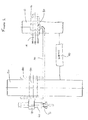
図1は、回転出力を有するシステムの第1の実施の形態を示す概略図、図2は、図1の左側から見たときの図1のシステムを示す図、図3は、図1の下側から見たときの図1のシステムを示す図である。
(Detailed explanation)
FIG. 1 is a schematic diagram showing a first embodiment of a system having a rotational output, FIG. 2 is a diagram showing the system of FIG. 1 when viewed from the left side of FIG. 1, and FIG. It is a figure which shows the system of FIG. 1 when it sees from the side.
第1の実施の形態では、伝達手段40を介して、駆動軸10を出力軸50に連結している伝達経路が構成されている。図1に示されているように、駆動軸10が回転すると、出力軸50が比例して回転することとなるように、伝達手段40は駆動軸10及び出力軸50の両方に連結されている。駆動軸10の動き及び力を出力軸50に伝達できるギヤ又はその他の適切な構成部品のいろいろな配置によって伝達手段40を構成することができる。伝達手段40は、所定のとおり、駆動軸10から伝達される動き及び力を変換及び/又は修正し、その修正された動きを出力軸50に適用できるように構成されている。
In the first embodiment, a transmission path that connects the
図1乃至図3に示すように、伝達経路に加えて、アレスタ経路(arrestor path)も設けられている。アレスタ経路は、駆動軸10が回転するとピン90がそれに比例した動き(a proportional motion)をすることとなるように、ピン90を延長アーム30を介して駆動軸10に連結している。図1に示された実施の形態では、ピン90はほぼ直線状の経路を移動する。出力軸50の回転及びピン90のほぼ直線状の移動は、駆動軸10の回転と関連している。
As shown in FIGS. 1 to 3, in addition to the transmission path, an arrester path is also provided. The arrester path connects the
ピン90は、出力軸50に形成されている案内路55を貫通し又は案内路55内に突出している。案内路は、出力軸50を貫通して延びているチャネルとして示されているが、出力軸50に形成されたスロット、出力軸50からの突起又はその他の適切な形に形成されたものとすることができるであろう。
The
出力軸の回転によりチャネルの異なる部分がピンのコースと整合するようにチャネル55は形成される。チャネル55の詳細な形状は図1乃至図3には示されていないが、チャネル55は、例えば、ほぼ螺旋形のあるいはカーブする斜めの外形を有することができるであろう。チャネル55の形状はピンの移動と出力軸の回転との間の期待される関係によって決まる。
The
システムが予期される回転出力をもたらすときは、ピン90がコースに沿って直線的に動き、出力軸50は回転する。駆動軸10がどのように回転しても、出力軸50が回転するとき、ピンのコースと整合しているチャネル55の部分がピン90の位置と一致するように、ピン90の直線的な動きは出力軸50の回転と同期する。例えば、出力軸50が回転すると、ピン90が、ほぼ直線状に動き続けている間中、チャネル55の対向する側面からほぼ等距離のままで、したがって、チャネル55の対向する側面と接触しないでいるように、システムを構成できる。これを容易にするために、チャネル55の形状は適切に構成されなければならず、軸50の回転及びピン90の直線状の動きは互いに同期しなければならない。
When the system provides the expected rotational output, the
出力軸50を回転させるためには、またしたがって、システムが出力を提供するためには、ピン90の直線状の動きは軸50の回転出力と同期しなければならない。同期すると、出力軸50が回転するにつれてピン90はチャネル55に沿って移動し、システムは出力を提供できることとなる。
In order for the
ピン90と軸50の同期した動きは、ピン90及び軸50を駆動する経路、すなわち、アレスタ経路及び伝達経路の構成要素に依存している。システムが期待どおりの出力を提供し続けるためには、伝達経路の構成要素及びアレスタ経路の構成要素は、出力軸50及びピン90を同期して動かし続けるように、出力軸50及びピン90に作用し続けなければならない。アレスタ経路又は伝達経路の構成要素が損傷又は摩耗した場合、ピン90及び出力軸50の相対的な動きはもはや同期しない。
The synchronized movement of the
同期が失われると、チャネル55の配置個所に対するピン90の位置はもはや期待又は意図されたようにはならない。この場合、ピン90及び/又は出力軸50が動き続けると、ピンがチャネル55の側壁に押し付けられることになり、出力軸50のさらなる回転は制限される。より詳しくは、ピン90とチャネル55の当接により、出力軸50の動きへの対抗力が生じ、出力軸50のさらなる回転が阻止される。この力の大きさは、システムが失った同期性の程度に依存している。
When synchronization is lost, the position of
2つの経路が同期性を失う(come out of synchronisation)ときにシステムが停止能力を有するということは、システムに障害が出て予期通りに機能しなくなったときに予期しない及び/又は望ましくないシステムの回転出力が阻止されることを意味している。この障害は、構成部品の1つ又はすべての完全な障害でなければならない必要は必ずしもなく、障害が一方の経路の構成部品の部分的な摩耗である状況も含んでいる。システムを停止させる磨耗の度合いは、どのぐらい精密にシステムを調整するかに依存する。例えば、チャネル55の表面とピン90の間の隙間を狭くすることによって、構成部品の軽微な摩耗の場合でも、システムをより停止しやすくできるであろう。ここで、狭い隙間は、ピン90又は出力軸50の一方の予期した動きからの非常にわずかなずれだけでも、ピン90とチャネル55の表面とが接触することになり、それゆえに、システムが停止することを意味する。あるいは、チャネル55の表面とピン90の間に大きい隙間を設けることは、構成部品の軽微な、場合によってはたいしたことのない摩耗だけではシステムを停止させることにはならないが、累積した又はさらに著しい磨耗あるいは障害によってシステムを停止させることができるであろう、ということを意味する。
The fact that the system has the ability to shut down when the two paths come out of synchronization means that an unexpected and / or undesirable system can fail when the system fails and fails to function as expected. This means that rotational output is blocked. This failure does not necessarily have to be a complete failure of one or all of the components, and includes situations where the failure is partial wear of a component in one path. The degree of wear that stops the system depends on how precisely the system is adjusted. For example, narrowing the gap between the surface of the
図1乃至図3に示された特定の形態(example)では、駆動軸10は歯付部分16と噛み合わされている。歯付部分16は、延長アーム30の第1の端部に取り付けられ又は一体化されている。延長アーム30の第2の端部はギヤ61と噛み合わされ、このギヤ61は、一連のさらなるギヤを介して、送りねじ部材60と噛み合っている。ピン90に取り付けられているナット70は、送りねじ部材60の回転によって、ナット70、したがってピン90が送りねじ部材60の軸とほぼ平行な方向に並進移動(translate)するように、送りねじ部材60と噛み合わされている。延長アーム30と送りねじ部材60を連結しているギヤの特定の構成は、ピン90の直線的動き(linear motion)を出力軸50の回転と同期させるためには、延長アーム30の動きをピン90のどの程度の直線的動きに変換する必要があるかによって決まる。ピン90の動き及び出力軸の回転とのピン90の同期化に影響する他の要因としては、送りねじ部材60の長さ及びねじピッチがあり得る。場合によっては、送りねじ部材60の一端に配置された単一のギヤで延長アーム30と送りねじ部材60を適切に連結することもあることに留意されたい。あるいは、ピン90は、延長アーム30の第2の端部又は他の部分に直接取り付けたり一体化したりすることができる。
In the specific example shown in FIGS. 1 to 3, the
ピン90は、出力軸50内のチャネル55内に貫通して突出しているが、ピン90がチャネル55内全体に突出する必要は必ずしもなく、むしろ一部だけチャネル55内に突出していることもあることに留意されたい。
The
駆動軸10が、それ自体でシステムに直接駆動力を供給するように構成できる。あるいは又はさらに、駆動機構によって駆動軸10が直接又は間接的に駆動されるように構成できる。図1乃至図3において、駆動機構は、システムの内側にあり、駆動軸10に間接的に作用している。この場合、歯付き部分16が、送りねじ部材14と噛み合わされたナット20に取り付けられ又は一体化されている。送りねじ部材14は、駆動機構、例えばアクチュエータによって駆動される。ここでは、駆動された送りねじ部材14によって歯付き部分16が直線移動し、駆動軸10を回転動させるが、それゆえ、駆動手段は間接的に駆動軸10を駆動することとなる。駆動機構はシステムの外側にあり駆動軸10に直接作用できるが、このような場合、歯付き部分16は延長アームをガイドする作用をなす軸によって支持されることができるということに留意されたい。
The
駆動軸10が歯付き部分16と噛み合わされる場合には、歯付き部分16は駆動軸10の回転に比例して直線移動してその結果、延長アーム30が直線移動することになる。延長アーム30の第2の端部とギヤ61との噛み合いによって、アーム30の直線移動をギヤ61の回転動に変換する。一連のギヤ61、62、63及び65を介して、延長アーム30の直線移動は、送りねじ部材60の回転動に変換される。送りねじ部材60はナット70と噛み合っているので、送りねじ部材60が回転すると、ナット70が直線移動し、したがって、送りねじ部材60の長さ方向の軸に沿ってピン90が直線移動する。ピン90の移動が出力軸50の回転と同期しているときには、出力軸50の回転につれて、ピン90は直線状のコースに沿って移動する。
When the
ピン90がねじ取り付けされている送りねじ部材60を使用し、自動ロック式アレスタを構成できる。特に、ピン90が直接又は間接的に送りねじ部材60とねじ係合しているので、送りねじ部材60が回転するとき、ピン90は直線状に移動できるだけである。したがって、アレスタ経路の形成時にピン90に力が加わってもピン90は移動せず、出力軸50は移動できないことになる。例えば、ピン90が出力軸50のチャネル55の側壁に当接していれば、出力軸はピン90に力を加えることができるであろう。送りねじ部材60が、ナット70及びピン90がスライド可能に係合する単なる軌道であるのならば、出力軸50によってピン90に力が加えられると、ピン90は軌道に沿ってスライドし、それゆえ、システム内で障害が起こったとしても、出力軸50は回転してしまうであろう。しかしながら、ナット70が送りねじ部材60のような自動ロック手段とねじ係合しているため、ナット70及びピン90の移動は送りねじ部材60の回転によってのみ達成され、したがって、ナット70及びピン90が出力軸50からの力によって長手方向に移動することはない。そこで、ピン90及び出力軸50の動きが同期しないようなシステム内の障害が起こると、ピン90に力が加わっても、加わった力によってピン90が直線状のコースに沿って移動することはなく、それゆえ、出力軸50は回転できず、システムは停止されたままとなる。
A self-locking arrester can be constructed using a
図1から分かるように、少なくともピン90の一部は、ガイド80内に突出し、このガイド80はピンのコースに対して固定されている。この形態では、ガイド80はシステムを収納しているケースのチャネルである。ガイド80は、ピン90を進行コースに沿ってガイドする手段として作用することに加え、例えば出力軸50の回転によって、ピン90がピンのコースから外れて動かないように補助する作用を行う。例えば、出力軸50が回転しているが、ピン90の動きと同期しない場合、チャネル55の側壁がピン90に当接する。出力軸50によって生じるモーメントは、ピン90に力を加えるような比較的大きいものである場合がある。ガイド80は、ピン90の支持されていない部分の長さを減らし、それによって、より小型のピンを、ケースと荷重を分担しながら使用できるようにする。さらに、ガイド80を使用することにより、システムの特性を変更でき、荷重の分離(isolating load)を助け、出力軸5から加えられた力が、ピン90とアレスタ経路の間の接続部に伝達されないようにしている。
As can be seen from FIG. 1, at least a portion of the
チャネル55と同様に、ガイド80の幅、したがって、ガイド面とピン90の表面との間の隙間又は距離は変えることができる。小さい隙間又は距離だと、ピン90の予期する動き又は角度がわずかに変化しただけで、面の間で接触が起きることを意味する。障害の際にシステムを停止する手段は、さらに、ピン90によって変形できるようなピン90より軟らかい材料でガイド80の面を形成又は被覆してもよい。しかしその材料は、ガイド80が変形してピン90の動きを抑制するように作用し、それによりシステムを停止させるのを補助できるような十分な強度を有している。
As with the
伝達経路とアレスタ経路が同期しないときに出力軸50の回転を防ぐことができることに加えて、アレスタの使用により、出力軸50が一定の範囲を超えて回転するのを防ぐことができる。これは、ピンのコースの範囲を制限することにより達成できる。ピンのコースの範囲は、例えば、チャネル55の長さを制限することにより、又は送りねじ部材60の長さを制限することにより、あるいはアレスタ経路がピン90に提供できる直線移動の距離を制限することにより達成できる。
In addition to preventing the
図1乃至図3は、システムが期待通りに作動しないときに回転を防止するアレスタ経路を1つ備えた回転システムを示している。しかしながら、他の実施の形態では、回転システムは、システムの回転を止めるための複数のアレスタ経路を有する場合がある。回転システムが複数のアレスタ経路を有している場合、システムが正しく作動して出力を提供するために、それぞれのアレスタ経路自体が伝達経路に対して同期し、したがって、互いに同期しなくてはならない。 FIGS. 1-3 illustrate a rotating system with a single arrester path that prevents rotation when the system does not operate as expected. However, in other embodiments, the rotating system may have multiple arrester paths to stop the rotation of the system. If the rotating system has multiple arrester paths, in order for the system to operate correctly and provide output, each arrester path itself must be synchronized to the transmission path and therefore must be synchronized with each other .
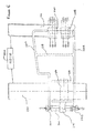
図4は、回転出力を提供するシステムの第2の実施の形態の概略図である。図4のシステムは第2のアレスタ経路を有している点が明らかな違いだが、図示された回転システムは図1に示されたものと類似している。 FIG. 4 is a schematic diagram of a second embodiment of a system for providing rotational output. The obvious difference is that the system of FIG. 4 has a second arrester path, but the rotating system shown is similar to that shown in FIG.
より具体的には、駆動軸110は第1及び第2の歯付き部分116A、116Bと噛み合い、第1及び第2の歯付き部分116A、116Bに対して回転する。第1及び第2の歯付き部分116A、116Bはそれぞれ、第1及び第2の延長アーム130A、130Bに一体化されているか、又は、取り付けられていて、そして、第1及び第2の延長アーム130A、130Bはそれぞれ、第1及び第2のギヤ161A、161Bと噛み合っている。第1のギヤ161Aは、一連のギヤを介して第1の送りねじ部材160Aに連結され、そして、この第1の送りねじ部材160Aは第1のナット170Aと噛み合っている。第2のギヤ161Bは、一連のギヤを介して第2の送りねじ部材160Bに連結され、そして、この第2の送りねじ部材160Bが第2のナット170Bと噛み合っている。しかしながら、第1及び第2のギヤ161A、161Bがそれぞれ、送りねじ部材160A、160Bと一連のギヤを介して噛み合う必要はなく、代わりに第1及び第2のギヤ161A、160Bをそれぞれ、送りねじ部材160A、160Bの一端に配置することもあり得ることに留意されたい。
More specifically, the
図5は図4のシステムの側面図である。図5に最もよく示されているが、細長い連結部材175が第1のナット170Aを第2のナット170Bに連結している。詳しくは、細長い連結部材175の第1の端部は第1のナット170Aに取り付けられ、又は、一体化されていて、一方、細長い連結部材175の第2の端部は、第2のナット170Bに取り付けられ、又は、一体化されている。ピン190は連結部材175に取り付けられ、又は、一体化されている。ピン190は、第1の実施の形態について記載したように、出力軸150内のチャネル155又はその他の案内路内に突出し、あるいはチャネル155又はその他の案内路を貫通して突出している。第1の実施の形態と同様に、ピン190も、ピンのコースに対して固定された、ピンのコースとほぼ平行なガイド80内に突出することができる。
FIG. 5 is a side view of the system of FIG. As best shown in FIG. 5, an elongated connecting member 175 connects the first nut 170A to the second nut 170B. Specifically, the first end of the elongated connecting member 175 is attached to or integral with the first nut 170A, while the second end of the elongated connecting member 175 is the second nut 170B. Are attached to or integrated with each other. The
図4及び図5に示された形態では、チャネル155は概略的にカーブする斜めの形状を有している。しかしながら、チャネル155は、この実施の形態では、又は他のどんな実施の形態でも、軸150の回転につれて、ピン190がピンのコースに沿って予定通りに動くのを可能とする他の適切な形状を有することができる。チャネル155の形状は、具体的なピンのコース及び出力軸50の意図された回転によって決まる。例えば、チャネル155が螺旋形又はS形状、直線状か湾曲した斜め形状、あるいは、放物線形状、又はそれらを組合せた形状とすることができる。
In the form shown in FIGS. 4 and 5, the
前の実施の形態と同様に、駆動軸110が回転すると出力軸150が回転することになるように、伝達経路は駆動軸110と出力軸150の両方に連結されている伝達手段140を有している。伝達手段140は、所定どおりに駆動軸110から伝達される動きや力を変換又は調整でき、調整した動きや力を出力軸55に加えることができるギヤ又は他の適切な構成部品で構成することが可能である。
As in the previous embodiment, the transmission path has transmission means 140 connected to both the
システムが所定の回転出力を供給するためには、このコースと整合するチャネル155の部分が、駆動軸110がどのように回転しても、ピン190の位置と一致するように、ピン190の直線移動は出力軸150の回転と同期しなければならない。しかしながら、2つの動きが、例えば伝達手段140の構成部品の障害のために同期しなければ、コースと整合する案内路155の部分はピン190の位置と一致しなくなり、ピンがチャネル155の側壁に当接して出力軸150のさらなる回転を制限する。
In order for the system to provide a predetermined rotational output, the portion of the
図4及び図5に示された実施の形態では、第1の歯付き部分116Aは、第2の歯付き部分116Bの面と径方向反対側の駆動軸110の面と噛み合っている。したがって、駆動軸110が回転すると、歯付き部分116A、116B及びそれらの対応する延長アーム130A、130Bは直線方向で反対方向に駆動されることになる。したがって、例えば、ナット17OA、17OBを両方とも確実に同じ方向に駆動するために、アレスタ経路のどちらか一方に追加のギヤを設けたり、送りねじ部材160A、160Bの一方に時計回りのねじを設け、他方に反時計回りのねじを設けたり、及び/又はアーム130A,130Bの相対的な位置及び構成を調整したりして、必要な作動出力を提供することとなるであろう。
In the embodiment shown in FIGS. 4 and 5, the first toothed portion 116 </ b> A meshes with the surface of the
送りねじ部材160A、160Bが異なる速度でそれぞれのナット170A、170Bを駆動する場合、連結部材175はねじれ、送りねじ部材160A、160Bに対してもはや垂直ではなくなる。ここでは、ナット170A、170Bは送りねじ部材160A、160Bのねじに引っかかってしまう。したがって、2つのアレスタ経路の一方に何らかの摩耗又は損傷がある場合には、ナット170A、170Bの移動は変化し、ナット170A、170Bは所定位置に固定されて、ピン190が移動できないようになり、したがって、出力軸150がさらに回転できず、システムが停止する。
When the
図6は、回転出力を有するシステムの第3の実施の形態の平面図である。本実施の形態では、第1のアレスタ経路と、第2のアレスタ経路が設けられている。本実施の形態では、アレスタ経路は、構成部品、すなわち、送りねじ部材260を共有している。第1のアレスタ経路の第1の延長アーム230Aは、送りねじ部材260の第1の端部に配置された第1のギヤ261Aと噛み合い、一方、第2のアレスタ経路の第2の延長アーム230Bは、送りねじ部材260の第2の端部に配置された第2のギヤ261Bと噛み合っている。ピン290に一体化された、又は取り付けられたナット270は、送りねじ部材260のねじと噛み合い、第1の実施の形態について記載されたように作用する。
FIG. 6 is a plan view of a third embodiment of a system having rotational output. In the present embodiment, a first arrester path and a second arrester path are provided. In the present embodiment, the arrester path shares components, that is, the
異なる駆動力が送りねじ部材260の両端に加えられるように2つのアレスタ経路の移動が同期していない場合、送りねじ部材260は回転せず、したがって、ピン290は移動せず、それによって、動かないピン290がチャネルの側壁に当接するために、出力軸250の回転は阻止される。
If the movements of the two arrester paths are not synchronized so that different driving forces are applied to both ends of the
オプションとしての、ブリッジ部材を第1及び第2の延長アーム230A、230Bの間に設けることができる。図6に示された実施の形態では、ブリッジ部材は伸縮可能な可撓性を有するブリッジ部材238である。例えば、可撓性のブリッジ部材238は、テレスコープ部材又は弾性材製とすることができる。このようなブリッジ部材238は、アーム230A、230Bが互いに同じ方向へ移動することを可能とし、また、アーム230A、230Bが互いに反対方向へ移動することも可能とする。しかしながら、アーム230A、230Bが互いに反対方向に移動するときは、ブリッジ部材はそれらの移動範囲を制限するよう作用する。
Optionally, a bridge member can be provided between the first and second extension arms 230A, 230B. In the embodiment shown in FIG. 6, the bridge member is a
代わりに、ブリッジ部材は剛性を有するものとすることができることに留意されたい。剛性を有するブリッジ部材は、アーム230A、230Bが同じ直線方向に移動するときに、アーム230A、230Bの構造的剛性を高めるための補助を行い、アーム230A、230Bが、互いに反対方向に移動しないようにする。 Note that the bridge member may instead be rigid. The rigid bridge member helps to increase the structural rigidity of the arms 230A and 230B when the arms 230A and 230B move in the same linear direction so that the arms 230A and 230B do not move in the opposite directions. To.
図7は、回転出力を有するシステムの第4の実施の形態の側面図である。この実施の形態では、案内路は、出力軸450を貫通して延びるチャネル455である。ピン490は、出力軸450のチャネル455を完全に貫通して突出し、第1の端部491Aが第1のナット470Aに取り付けられ、又は一体化されていて、第2の端部491Bが第2のナット470Bに取り付けられ、又は一体化されている。ナット470A、470Bはそれぞれ、その対応する送りねじ部材460A、460Bと噛み合っている。ピンのそれぞれの端部491A、491Bは、異なるアレスタ経路によって駆動軸410に連結されている。すなわち、駆動軸410が回転するとピン490の各端部が移動することになるように、ピンの第1の端部491Aは第1のアレスタ経路を介して駆動軸410に連結され、ピンの第2の端部491Bは第2のアレスタ経路を介して駆動軸410に連結されている。
FIG. 7 is a side view of a fourth embodiment of a system having a rotational output. In this embodiment, the guide path is a
システムが所定の回転出力を提供するためには、ピン490がチャネル455の側壁に当接しないで、ピンのコースに沿ってピン490が移動し、出力軸が回転するといったように、ピンの両端部491A、491Bの移動が出力軸450の回転動と同期しなければならない。ピンの端部491A、491Bそれぞれの移動は、それらのそれぞれのアレスタ経路によって支配されるので、両方のアレスタ経路は、システムが出力を提供するために、出力軸455の回転と同期しなければならない。
In order for the system to provide a predetermined rotational output, the
図7に示された実施の形態では、両方のアレスタ経路の入力部は、それぞれの歯付き部分416A、416Bを介して、駆動軸410に直接連結され、アレスタ経路は第1の実施の形態についての記載とほぼ同様に機能する。しかしながら、アレスタ経路の一方又は両方は、アレスタ経路が間接的に駆動軸410に連結されるように、代わりにシステム内の他の構成部品から入力を受けることができる。例えば、第2のアレスタ経路が伝達手段440内の構成部品、例えば回転ギヤから入力を受けるように、システムを構成することができる。
In the embodiment shown in FIG. 7, the inputs of both arrester paths are directly connected to the
駆動軸が回転することにより、第2のアレスタ経路が連結された回転ギヤが回転し、したがって、第2のアレスタ経路は間接的に駆動軸410に連結されていることになる。
As the drive shaft rotates, the rotation gear to which the second arrester path is connected rotates, and therefore the second arrester path is indirectly connected to the
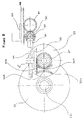
図8は、システムの第5の実施の形態を示している。この実施の形態では、延長アーム330を有するアレスタ経路が設けられている。延長アーム330は、前の実施の形態について記載したものと同様の方法で、駆動軸に噛み合わされている。延長アーム330は、歯付ラック368及び一連のギヤ361、362、363、364を介して送りねじ部材360に噛み合わされている。ナット370が、送りねじ部材360のねじに噛み合わされている。ナット370は、ギヤ377と噛み合っている歯付き部材373に取り付けられ、又は一体化されている。ギヤ377は、第1のピン390A及び第2のチャネル355Aを有する第1のディスク352に取り付けられ、又は一体化されている。第1のピン390Aは、第2のディスク354の第1のチャネル355B内に突出している。第2のディスク354は、第1のディスクとほぼ平行な面上に配置され、第1のディスク352の第2のチャネル355A内に突出する第2のピン390Bを有している。
FIG. 8 shows a fifth embodiment of the system. In this embodiment, an arrester path having an
図9は図8のシステムの平面図である。図9から分かるように、第2のディスク354は、出力軸350が回転すると第2のディスク354が回転するように、出力軸350に連結されている。第2のディスク354もまた、出力軸350に一体化できることに留意されたい。
FIG. 9 is a plan view of the system of FIG. As can be seen from FIG. 9, the
他の実施の形態と同様に、駆動軸310が回転すると出力軸350が回転することとなるように、伝達経路が駆動軸310を出力軸350に伝達手段340を介して連結している。
As in the other embodiments, the transmission path connects the
アレスタ経路では、駆動軸310が回転すると延長アーム330が、図9で左から右に、そして、右から左に直線移動することになる。この結果、歯付きラック368が直線移動してギヤ361、362、363、364が回転し、このギヤの回転にしたがって送りねじ部材360が回転することになる。送りねじ部材を回転させることにより、ナット370を直線移動させ、その結果、ギヤ377と第1のディスク352を回転させる。
In the arrester path, when the
システムが所定の又は求められる回転出力を提供するときは、第1及び第2のピン390A、390Bがそれぞれのチャネル355B、355Aに沿って移動するように、ディスク352、354が互いに同期して回転動を行う。ディスク352、354が同期して回転しなければ、第1及び第2のピン390A、390Bは、それぞれのチャネル355B、355Aの側壁に当接し、ディスク352、354を停止させ、それによって、ディスク352,354のさらなる回転、したがって、出力軸350のさらなる回転を制限する。
When the system provides a predetermined or desired rotational output, the
同期化に加えて、図8及び図9に示されているシステムが所定の回転出力を提供するためには、ディスク352、354は互いに反対方向に回転しなければならない。これは、それぞれのディスク352、354の回転を一方向だけに制限する趣旨ではなく、正しくは、一方のディスクが一方向へ回転するときに他方のディスクは反対方向に回転することを要求するものである。例えば、第1のディスクが時計回り方向に回転する場合は第2のディスクは反時計回り方向に回転し、そして、この逆の場合もある。ディスク352、354が同じ方向に回転し、又は同期しないで回転するときは、第1及び第2のピン390A、390Bがそれぞれのチャネル355B、355Aの側壁に当接し、それゆえ、ディスク352、354の回転が阻害されることとなるような形状をチャネル355A、355Bは有している。
In addition to synchronization, the
ディスク352、354の回転量、したがって、出力軸350の回転量は、ピン390A、390Bの移動が、チャネル355B、355Aの閉じられた端部で制約されることにより、制限されることに留意すべきである。
Note that the amount of rotation of the
図8及び図9に示された実施の形態では、延長アーム330は、送りねじ部材360及び一連のギヤを介して第1のディスク352に連結されている。選択された特定の構成は、第1のディスク352の回転を第2のディスク354の回転と同期させるために、延長アーム330の動きを第1のディスク352のどの程度の回転動に変換すべきかに、及び/又は駆動軸310の第1のディスクに対する相対的な位置に基づいている。しかしながら、場合によっては、送りねじ部材360の一端に配置された単一のギヤで、延長アーム330及び送りねじ部材360を適切に連結できるであろう。
In the embodiment shown in FIGS. 8 and 9, the
第1及び第2のディスクは円形である必要はなく、他の要求されるどのような形状でもよいことに留意されたい。 Note that the first and second discs need not be circular, but can be any other required shape.
図10は回転出力を有するシステムの第6の実施の形態の平面図である。前の実施の形態と同様に、駆動軸510が回転すると出力軸550が回転することになるように、駆動軸510を出力軸550に連結する伝達手段540を有する伝達経路が設けられている。
FIG. 10 is a plan view of a sixth embodiment of a system having rotational output. As in the previous embodiment, a transmission path having transmission means 540 for connecting the drive shaft 510 to the
伝達経路に加えて、システムは2つのアレスタ経路を有するが、図10では、1つのみ全体が示されている。第1のアレスタ経路では、図10に示されているように、駆動軸510を回転することにより傘歯車を介して連結されている中間軸531、532が回転することになり、したがって第1のリングギヤ561Aが回転することになる。出力軸550は、それらの回転に直接連動しないで第1のリングギヤを通過している。
In addition to the transmission path, the system has two arrester paths, but in FIG. 10, only one is shown overall. In the first arrester path, as shown in FIG. 10, by rotating the drive shaft 510, the
第1のリングギヤ561Aは、第1の上側ギヤ567A及び第1の下側ギヤ567Bと部分的に(partially)噛み合っている。これは、第1のリングギヤ561Aと第1の上側及び下側ギヤ567A、567Bの端面図(端部から視た図)である図11で最もよくわかる。第1の上側及び下側ギヤ567A、567Bは、上側送りねじ部材560A及び下側送りねじ部材560Bそれぞれの第1の終端に連結されている。上側及び下側の送りねじ部材560A、560Bのねじは、上側及び下側ナット570A、560Bそれぞれと噛み合っている。図5に示されたものと同様の方法で、細長い連結部材575が、第1のナット570Aを第2のナット570Bに連結している。ピン590は連結部材575に取り付けられ、又は一体化され、出力軸550のチャネル555内に突出している。したがって、歯付き部分585が第1の上側及び下側ギヤ567A、567Bと噛み合うとき、第1のリングギヤ561Aが回転すると、送りねじ部材560A、560Bが回転し、したがって、ピン590が直線移動することになる。
The
図11で分かるように、第1のリングギヤ561Aは、第1及び第2の歯付き部分585を介して上側及び下側ギヤ567A、567Bと部分的に噛み合っている。歯付き部分585は、第1のリングギヤ561Aの外面の径方向両側部分に配置されていて、それぞれが、第1のリングギヤ561Aの周のほぼ4分の1を占めている。したがって、第1のリングギヤ561Aが連続的に回転すると、歯付き部分585は第1の上側及び下側ギヤ567A、567Bと交互に噛み合い、1回の噛み合いは、ほぼ90度回転する間行われる。
As can be seen in FIG. 11, the
本実施の形態では、ナット570A、570Bがそれぞれの送りねじ部材560A、560Bの一端に位置していると、歯付き部分585が第1の上側及び下側のギヤ567A、567Bと係合し、ナット570A、57Bがそれぞれの送りねじ部材560A、560Bの他端に達すると、歯付き部分585が第1の上側及び下側のギヤ567A、567Bから外れるように、第1のアレスタ経路は調整されている。
In the present embodiment, when the nuts 570A and 570B are positioned at one ends of the respective
第1のアレスタ経路に加えて、第2のアレスタ経路が設けられている。第2のアレスタ経路は、駆動軸510が回転すると延長アーム530が直線移動することになるように、駆動軸510に連結されている延長アーム530を有している。延長アーム530は、延長アーム530が直線移動すると第2のリングギヤ561Bが回転することになるように、第2のリングギヤ561Bと噛み合っている。
In addition to the first arrester path, a second arrester path is provided. The second arrester path has an
第2のリングギヤ561Bは、第2のリングギヤ561Bの第1及び第2の歯付き部分を介して、第2の上側及び下側ギヤ568A、568Bと部分的に(partially)噛み合っている。第2のリングギヤ561Bの歯付き部分は、第1のリングギヤ561Aのものとほぼ同じであるが、第1のリングギヤ561Aの歯付き部分585の間の隙間と一致するように、角度がずらされている。このようにして、第2のリングギヤ561Bの歯付き部分は、ナット570A、570Bがそれぞれの送りねじ部材560A、560Bの一端に位置していると、第2の上側及び下側ギヤ568A、568Bそれぞれと係合し、ナット570A、57Bがそれぞれの送りねじ部材560A、560Bの他端に達すると、第1の上側及び下側ギヤ567A、567Bから外れる。
The
第1及び第2のアレスタ経路は、第1のリングギヤ561Aが第1の上側及び/又は下側ギヤ567A、567Bと係合するときは、第2のリングギヤは第2の上側及び/又は下側リングギヤ568A、568Bと係合せず、第2のリングギヤ561Bが第2の上側及び/又は下側ギヤ568A、568Bと係合するときは、第1のリングギヤ561Aが第1の上側及び/又は下側リングギヤ567A、567Bと係合しないように配置されている。
The first and second arrester paths are such that when the
第1及び第2のアレスタ経路は、第1のリングギヤ561Aがピン590を第1の方向に直線移動させ、一方、第2のリングギヤ561Bが、第1の方向と反対の第2の方向にピン590を直線移動させるように配置される。例えば、第1のリングギヤ561Aは第2のリングギヤ561Bと反対方向に回転できるように構成される。この場合、第1のリングギヤ561Aの歯付き部分585が第1の上側及び下側ギヤ567A、567Bと係合すると、送りねじ部材560A、560Bが回転し、したがって、ピン590が第1の方向に直線移動することになる。
In the first and second arrester paths, the
第1のリングギヤ561Aが一定量回転した後、第1のリングギヤ561Aの歯付き部分585は第1のギヤ567A、567Bから外れ、送りねじ部材はもはや回転せず、したがって、ピン590の第1の方向への移動も生じない。この時点で、第2のリングギヤの歯付き部分587は、第2の上側及び下側のギヤ568A、568Bと噛み合うようになり、したがって、送りねじ部材560A、560Bの回転が引き起こされる。第2のリングギヤ561Bは第1のリングギヤ561Aと反対方向に回転しているので、第2のリングギヤ561Bの回転はただちに(now)、ピン590を第1の方向と反対の第2の方向に直線状に移動させる。
After the
システムが所定の回転出力を提供しているときは、第1のリングギヤ561Aは、ピン590に接続されると、ピンを第1の方向に直線移動させ、第2のリングギヤ561Bは、ピン590に接続されると、第1の方向とは反対の第2の方向にピンを直線移動させる。これらの流れ(formats)のどの時点でも第1及び第2のリングギヤ561A、561Bの一方のみがピン590に接続されることができるので、また、第1及び第2のリングギヤ561A、561Bは、接続時間を交互にしてピン590に接続されるので、第1及び第2のリングギヤ561A、561Bが連続して回転すると、ピンが直線状のピンのコースに沿って前後に移動することになる。
When the system is providing a predetermined rotational output, when the
システムが所定の出力を提供しているときは、ピン590の直線移動は軸550の回転出力と同期している。すなわち、駆動軸510がどのように回転しても、ピンのコースと整合するチャネル555の部分がピンの位置と一致するように、ピン590の直線移動は軸550の回転動と同期する。両方のアレスタ経路がピン590を直線状に動かすので、両方のアレスタ経路は出力軸の回転に対して、したがって互いに、同期する。特に、ピン590の直線状のコースに沿った前後への移動は、これらの流れの中で、リングギヤ561A、561Bの一方が送りねじ部材560A、560Bと係合してピン590を移動させると、他方のリングギヤは送りねじ部材560A、560Bと係合せず、したがってピン590の移動を生じさせないように構成されているアレスタ経路に依存している。しかしながら、アレスタ経路の一方に、所定通りにはもはや作動できないような障害が発生すると、他方のリングギヤが上側及び下側ギヤそれぞれに、そして送りねじ部材560A、560Bに係合している時点で、一方のアレスタ経路はそのアレスタ経路のリングギヤを上側及び下側のギヤそれぞれに、したがって送りねじ部材560A、560Bに係合させ始める。この場合、第2のリングギヤ561Bが送りねじ部材560A、560Bと係合しているのに、第1のリングギヤ561Aが、送りねじ部材560A、560Bと係合することとなる。リングギヤ同士は異なる方向に回転しているので、それぞれのリングギヤは送りねじ部材560A、560Bの端部に反対方向の回転力を加えることになる。したがって、送りねじ部材560A、560Bは動かなくなり、それゆえ、ピン590はもはや直線状のコースに沿って移動せず、それによって、出力軸550のさらなる回転が防止される。
When the system is providing a predetermined output, the linear movement of
同様に、伝達経路に所定通りにはもはや作動できないような障害が発生すると、出力軸550はもはや所定通りに回転しない。このような場合、出力軸550の回転とピン590の直線移動の間の同期性は失われる。ピン590及び出力軸550の動作が同期しなくなる場合、ピンが案内路の側壁に当接して出力軸のさらなる回転を制限するように、コースと整合している案内路の部分は、ピンの位置に一致しないこととなる。
Similarly, if a failure occurs in the transmission path that can no longer be performed as predetermined, the
システムが所定の回転出力を提供しているときは、ピン590はチャネルに沿って前後に移動し、出力軸550は回転する。図10に示された実施の形態では、出力軸は連続的に回転し、したがって、出力軸550が回転し、ピン590が、チャネル555の側壁に当接しないでチャネルに沿って前後に移動するように、チャネルは適当な形状を備えている。例えば、チャネル555は、終端同士を接続して連続したループ形状を構成するような連続チャネルとすることができる。
When the system is providing a predetermined rotational output, the
図10は、それぞれがナットを駆動する2本の送りねじ部材の間に、ピンを支持する連結部材を設けた構成(図5に示されたものと同様の形)を示しているが、単一の送りねじ部材を、単一のナット及び関連するピン(図1乃至図3に示されたものと同様の形)とともに使用できることに留意されたい。 FIG. 10 shows a configuration (similar to that shown in FIG. 5) in which a connecting member for supporting a pin is provided between two feed screw members each driving a nut. Note that one lead screw member can be used with a single nut and associated pin (similar to that shown in FIGS. 1-3).
また、2つのリングギヤの歯付き部分が互いにずらされているなら、そして2つ以上の送りねじ部材が互いに同期して駆動されるのならば、リングギヤが有する歯付き部分を少なくすることも多くすることもできることに留意されたい。 Further, if the toothed portions of the two ring gears are shifted from each other, and if two or more feed screw members are driven in synchronization with each other, the toothed portions of the ring gear are often reduced. Note that you can also.
図10は、2つのアレスタ経路、すなわち第1のリングギヤ561Aを駆動する図の左側の第1のアレスタ経路と、第2のリングギヤ561Bを駆動する図の右側の第2のアレスタ経路を示している。しかしながら、代わりに、図の左側に第1のリングギヤ561Aを駆動するための1つ以上のアレスタ経路を有することができることに留意されたい。その代わりに又は追加的に、図の右側に第2のリングギヤ561Bを駆動するための1つ以上のアレスタ経路を有することができる。図のどちら側のアレスタ経路も、駆動軸510が回転するとピン590が移動することになるように、ギヤ、傘歯車、又は他の適切な構成部品を適切に配置して構成できる。
FIG. 10 shows two arrester paths, that is, a first arrester path on the left side of the drawing for driving the
図12は回転出力を有するシステムの第7の実施の形態の平面図である。本実施の形態では、駆動軸614及び出力軸650は、それらの長さ方向の軸が互いに直交するように配置されている。したがって、本発明は、駆動軸及び出力軸が互いに異なる方向を向いている回転システムとして具体化されることとなることに留意されたい。
FIG. 12 is a plan view of a seventh embodiment of a system having rotational output. In the present embodiment, the
図12は、駆動軸10が回転すると出力軸50が回転することになるように、伝達経路が駆動軸614を出力軸650に連結する一方法を示している。本実施の形態では、駆動軸610は送りねじ部材である。駆動軸610のねじはナット620と噛み合っている。駆動軸610が回転すると延長アーム630が移動することになるように、ナット620は延長アーム630に取り付けられ、又は一体化されている。延長アーム630の一端は、送りねじ部材 660の一端に位置する少なくとも1つのギヤと直接噛み合っている。したがって、駆動軸610が回転すると、延長アーム630の直線移動によって送りねじ部材660が回転することになる。
FIG. 12 shows one way in which the transmission path connects the
ナット670は、ピン690に取り付けられ、又は一体化されている。送りねじ部材660が回転するとナット670及びピン690が直線移動することになるように、ナット670は送りねじ部材660のねじと噛み合っている。したがって、駆動軸610が回転すると、延長アーム630及び送りねじ部材660を介して、ピン690が比例して直線移動することになる。
The
ピン690は、回転軸(rotatable shaft)658のチャネル655内に突出している。回転軸658は、出力軸650が回転すると回転軸658が回転し、したがってチャネル655が回転することになるように、接続手段651を介して出力軸650に連結されている。
The pin 690 protrudes into the channel 655 of the rotable shaft 658. The rotation shaft 658 is coupled to the
図12に示された形態では、伝達経路は、延長アーム630に取り付けられ、又は一体化されているトランスミッションアーム645を有している。したがって、延長アーム630と同様に、駆動軸610が回転すると、トランスミッションアーム645が直線移動することになる。トランスミッションアーム645の一端は、ギヤ642の少なくとも1つと噛み合っている。トランスミッションアーム645が直線移動すると出力軸650が回転することになるように、ギヤ642は出力軸650に取り付けられ、又は一体化されている。出力軸650は回転軸658に連結されているので、出力軸650が回転すると回転軸658が回転することになる。したがって、駆動軸610が回転するように駆動されると、ピン690が比例して直線移動し、回転軸658及びチャネル655が比例して回転することになる。
In the configuration shown in FIG. 12, the transmission path has a
システムが所定の出力を提供しているときは、ピン690はチャネル655に沿って移動し、出力軸650及び回転軸658は回転する。すなわち、ピン690のいかなる直線移動、及び/又は、出力軸650や回転軸658のいかなる回転に対しても、出力軸650が回転するにつれてチャネル655の少なくとも一部がピン690の位置と一致するように、ピン690の直線移動は出力軸650の回転と同期する。
When the system is providing a predetermined output, pin 690 moves along channel 655 and
Claims (20)
駆動軸と、
前記駆動軸が回転するとピンのコースに沿ってピンが移動することになるように前記ピンを前記駆動軸に連結するアレスタ経路と、
前記システムからの出力を供給するか、又は前記システムからの出力を供給する軸に連結された出力軸であり、この出力軸が回転すると、異なる部分が前記ピンのコースと整合するように構成されている案内路と結び付けられた出力軸と、
前記駆動軸が回転すると前記出力軸が回転することになるように、前記駆動軸を前記出力軸に連結する伝達経路(transmission path)と、を備え、
前記ピンの移動が前記出力軸の回転と同期しているときは、前記駆動軸がどのように回転していても、前記ピンのコースと整合する前記案内路の前記部分は前記ピンの位置と一致し、
前記ピンの移動が前記出力軸の回転と同期していないときは、前記ピンのコースと整合する前記案内路の前記部分は、前記ピンが前記案内路の側壁に当接して前記出力軸のさらなる回転を制限するように、前記ピンの位置とは一致しないように構成されている、ことを特徴とするシステム。 A system having a rotational output,
A drive shaft;
An arrester path connecting the pin to the drive shaft so that the pin moves along the course of the pin as the drive shaft rotates;
An output shaft connected to a shaft that supplies the output from the system or that supplies the output from the system, and when the output shaft rotates, different portions are configured to align with the course of the pin An output shaft associated with the guideway
A transmission path for connecting the drive shaft to the output shaft so that the output shaft rotates when the drive shaft rotates,
When the movement of the pin is synchronized with the rotation of the output shaft, no matter how the drive shaft is rotating, the portion of the guide path that is aligned with the course of the pin is the position of the pin. Match
When the movement of the pin is not synchronized with the rotation of the output shaft, the portion of the guide path that is aligned with the course of the pin is further in contact with the side wall of the guide path. The system is configured not to coincide with the position of the pin so as to limit rotation.
前記出力軸と結び付けられている第2のピン及び案内路が第2の回転部材に設けられ、前記第2の回転部材は、前記駆動軸が回転すると、前記第2のピンが概略的にカーブしている第2のコースに沿って移動することになるように、前記出力軸に連結されていて、
前記第1の回転部材の回転が前記第2の回転部材の回転と同期していると、前記第2のピンは前記第2の案内路に沿って移動し、前記第1の回転部材に連結されている前記ピンは前記第2の回転部材と結び付けられている前記案内路に沿って移動し、
前記第1の回転部材の回転が前記第2の回転部材の回転と同期しないときには、前記第2のピンは前記第2の案内路の側壁に当接し、前記第1の回転部材に連結された前記ピンは、前記第2の回転部材の前記案内路の前記側壁に当接して、前記出力軸がさらに回転するのを防ぐように構成されている、ことを特徴とする請求項19記載のシステム。 The pin is provided on a first rotating member, and the first rotating member has a second guide path, and when the drive shaft rotates, the rotating member, the pin, and the second guide path are Arranged to rotate,
A second pin and a guide path connected to the output shaft are provided in the second rotating member. The second rotating member is configured such that when the drive shaft rotates, the second pin is approximately curved. Connected to the output shaft so as to move along the second course,
When the rotation of the first rotating member is synchronized with the rotation of the second rotating member, the second pin moves along the second guide path and is connected to the first rotating member. The pin being moved moves along the guide path associated with the second rotating member;
When the rotation of the first rotation member does not synchronize with the rotation of the second rotation member, the second pin abuts against the side wall of the second guide path and is connected to the first rotation member. The system of claim 19, wherein the pin is configured to abut against the side wall of the guide path of the second rotating member to prevent further rotation of the output shaft. .
Applications Claiming Priority (11)
| Application Number | Priority Date | Filing Date | Title |
|---|---|---|---|
| GB0902448.0 | 2009-02-16 | ||
| GB0902436.5 | 2009-02-16 | ||
| GB0902446.4 | 2009-02-16 | ||
| GB0902445A GB0902445D0 (en) | 2009-02-16 | 2009-02-16 | Corcost-t4 |
| GB0902445.6 | 2009-02-16 | ||
| GB0902436A GB0902436D0 (en) | 2009-02-16 | 2009-02-16 | Corcost-T6 |
| GB0902448A GB0902448D0 (en) | 2009-02-16 | 2009-02-16 | Corcost-T2 |
| GB0902446A GB0902446D0 (en) | 2009-02-16 | 2009-02-16 | Corcost-T4 |
| GB0902618.8 | 2009-02-17 | ||
| GB0902618A GB0902618D0 (en) | 2009-02-17 | 2009-02-17 | Corcost-T5 |
| PCT/GB2010/000255 WO2010092349A1 (en) | 2009-02-16 | 2010-02-12 | Arrestor |
Publications (2)
| Publication Number | Publication Date |
|---|---|
| JP2012518133A true JP2012518133A (en) | 2012-08-09 |
| JP2012518133A5 JP2012518133A5 (en) | 2013-04-04 |
Family
ID=42133684
Family Applications (4)
| Application Number | Title | Priority Date | Filing Date |
|---|---|---|---|
| JP2011549653A Pending JP2012518133A (en) | 2009-02-16 | 2010-02-12 | Arresta |
| JP2011549652A Pending JP2012518132A (en) | 2009-02-16 | 2010-02-12 | Gear box |
| JP2011549655A Pending JP2012518375A (en) | 2009-02-16 | 2010-02-12 | Linear actuator |
| JP2011549650A Pending JP2012518131A (en) | 2009-02-16 | 2010-02-12 | Link mechanism |
Family Applications After (3)
| Application Number | Title | Priority Date | Filing Date |
|---|---|---|---|
| JP2011549652A Pending JP2012518132A (en) | 2009-02-16 | 2010-02-12 | Gear box |
| JP2011549655A Pending JP2012518375A (en) | 2009-02-16 | 2010-02-12 | Linear actuator |
| JP2011549650A Pending JP2012518131A (en) | 2009-02-16 | 2010-02-12 | Link mechanism |
Country Status (6)
| Country | Link |
|---|---|
| US (4) | US20110284338A1 (en) |
| EP (4) | EP2396569A1 (en) |
| JP (4) | JP2012518133A (en) |
| CN (4) | CN102317650A (en) |
| CA (4) | CA2750757A1 (en) |
| WO (4) | WO2010092346A1 (en) |
Families Citing this family (28)
| Publication number | Priority date | Publication date | Assignee | Title |
|---|---|---|---|---|
| CA2750757A1 (en) * | 2009-02-16 | 2010-08-19 | Corcost Limited | Linear actuator |
| GB2480423A (en) * | 2010-03-15 | 2011-11-23 | Jena Rotary Technolgy Ltd | Valve system |
| MX2013003201A (en) * | 2010-09-24 | 2013-07-03 | Danaher Corp | Linear actuator. |
| CN102562992B (en) * | 2010-12-24 | 2014-07-16 | 第一传动科技股份有限公司 | High-load linear actuator |
| US8733192B2 (en) | 2011-03-11 | 2014-05-27 | Timotion Technology Co., Ltd. | High-load linear actuator |
| GB201106974D0 (en) | 2011-04-26 | 2011-06-08 | Corcost Ltd | Actuator cam |
| GB201113194D0 (en) | 2011-07-31 | 2011-09-14 | Corcost Ltd | Corcost-TE22344 |
| US9295598B2 (en) * | 2011-12-09 | 2016-03-29 | Stryker Corporation | Patient support backrest release and actuator assembly |
| DE102012211062A1 (en) * | 2012-06-27 | 2014-01-02 | Stabilus Gmbh | Drive device and construction kit for such a drive device |
| JP5706859B2 (en) * | 2012-09-20 | 2015-04-22 | 富士重工業株式会社 | engine |
| DE102013102280A1 (en) * | 2013-03-07 | 2014-09-11 | Giuseppe Giampietro | Device with hollow piston |
| JP6294606B2 (en) * | 2013-08-20 | 2018-03-14 | 株式会社アイカムス・ラボ | Linear motion device |
| JP2015120238A (en) * | 2013-11-20 | 2015-07-02 | 株式会社東芝 | Conveyance support device |
| DE102014100444B4 (en) * | 2014-01-16 | 2017-06-29 | MAQUET GmbH | Device for linear displacement of a patient support surface and method for mounting such a device |
| CN104200739B (en) * | 2014-09-01 | 2016-08-17 | 重庆交通大学 | The compound teaching aid of planar linkage mechanism and presentation control method thereof |
| GB2547182B (en) * | 2015-12-10 | 2021-04-21 | Cmr Surgical Ltd | Measuring robot performance |
| KR20200122415A (en) | 2016-05-12 | 2020-10-27 | 골든 리뉴어블 에너지 엘엘씨 | Cyclonic condensing and cooling system |
| US10436525B2 (en) | 2016-05-12 | 2019-10-08 | Golden Renewable Energy, LLC | Cyclonic cooling system |
| AU2017282172B2 (en) | 2016-06-21 | 2022-01-20 | Golden Renewable Energy, LLC | Char separator and method |
| US10961062B2 (en) | 2016-06-21 | 2021-03-30 | Golden Renewable Energy, LLC | Bag press feeder assembly |
| US20170361268A1 (en) | 2016-06-21 | 2017-12-21 | Golden Renewable Energy | Char separator |
| US10813807B2 (en) * | 2016-06-29 | 2020-10-27 | Stryker Corporation | Patient support systems with hollow rotary actuators |
| SG11201811050PA (en) | 2016-07-05 | 2019-01-30 | Golden Renewable Energy Llc | System and process for converting waste plastic into fuel |
| US10233393B2 (en) * | 2016-07-08 | 2019-03-19 | Golden Renewable Energy, LLC | Heated airlock feeder unit |
| US10518372B2 (en) * | 2016-09-12 | 2019-12-31 | Kindred Systems Inc. | Compound prismatic platforms for use in robotic systems |
| CN107095468A (en) * | 2016-11-16 | 2017-08-29 | 程建强 | A kind of accounting finance cabinet |
| US10471580B1 (en) * | 2016-11-22 | 2019-11-12 | Shelby Lies | Multi-purpose tool |
| CN109223506B (en) * | 2018-11-21 | 2021-05-04 | 南阳市中心医院 | External chest pressing device for cardio-pulmonary resuscitation |
Family Cites Families (57)
| Publication number | Priority date | Publication date | Assignee | Title |
|---|---|---|---|---|
| US2541529A (en) * | 1949-06-06 | 1951-02-13 | Graham D Mcvicker | Actuator for power-operated adjustable beds |
| US3338140A (en) * | 1965-08-16 | 1967-08-29 | John M Sheesley | Actuator |
| US3628645A (en) * | 1969-10-23 | 1971-12-21 | Ncr Co | Carriage drive mechanism |
| US3935754A (en) * | 1974-06-14 | 1976-02-03 | The Boeing Company | Failure detector and indicator for aircraft flap actuation system |
| NL169808C (en) * | 1974-10-14 | 1982-08-16 | Philips Nv | FREQUENCY SELECTOR WITH FREEWHEEL COUPLING. |
| US4013019A (en) * | 1975-11-25 | 1977-03-22 | Cgr Medical Corporation | Drive for tiltable X-ray table |
| US4015824A (en) * | 1976-04-05 | 1977-04-05 | Templeton, Kenly & Company | Jack safety stop |
| US4282442A (en) * | 1979-07-11 | 1981-08-04 | Heinrich Massinger | Device for converting reciprocal linear motion to continuous rotary motion |
| FI60817C (en) * | 1980-08-26 | 1982-04-13 | Tampella Oy Ab | EXCENTAL ADJUSTMENT |
| US4440035A (en) * | 1981-05-18 | 1984-04-03 | Dana Corporation | Slip clutch speed change mechanism |
| SE425688B (en) * | 1981-11-06 | 1982-10-25 | Skf Nova Ab | DEVICE FOR TRANSFORMING LINEAR MOVEMENT TO ROTATION MOVEMENT |
| EP0108657B1 (en) * | 1982-09-25 | 1987-08-12 | Fujitsu Limited | A multi-articulated robot |
| SE443033B (en) * | 1983-01-25 | 1986-02-10 | Skf Nova Ab | RORELSEOVERFORINGSANORDNING |
| JPS6073163A (en) * | 1983-09-30 | 1985-04-25 | Fujitsu Ltd | Construction of screw shaft |
| JPS60155391A (en) * | 1984-01-25 | 1985-08-15 | 斎藤 之男 | Joint for manipulator, etc. |
| US4563908A (en) * | 1984-03-14 | 1986-01-14 | Plessey Incorporated | High speed, dual operated electromechanical actuator |
| JPS60204594A (en) * | 1984-03-29 | 1985-10-16 | 川村工業株式会社 | Lifter |
| US4568218A (en) * | 1984-07-16 | 1986-02-04 | Wacker Corporation | Adjustably controllable centrifugal vibratory exciter |
| JPS6220957A (en) * | 1985-07-19 | 1987-01-29 | Sanyo Electric Co Ltd | Power transmission mechanism of serial link |
| JPS62193790A (en) * | 1986-02-19 | 1987-08-25 | 三菱重工業株式会社 | Flexible robot arm |
| US4696512A (en) * | 1986-03-06 | 1987-09-29 | Berkline Corporation | Motorized recliner chair with release mechanism |
| US4794655A (en) * | 1986-04-25 | 1989-01-03 | Agency Of Industrial Science & Technology | Truck type patient-moving device |
| JPS6443093U (en) * | 1987-09-08 | 1989-03-15 | ||
| US4944056A (en) * | 1988-09-28 | 1990-07-31 | The Research Foundation Of State University Of Ny | Method and apparatus for transporting a disabled person |
| US4911033A (en) * | 1989-01-03 | 1990-03-27 | Ross-Hime Designs, Incorporated | Robotic manipulator |
| NL9000711A (en) * | 1990-03-26 | 1991-10-16 | Petrus Johannes Lambertus De L | SCREW STAMP FOR SUPPORTING FORMWORKS IN CONSTRUCTION. |
| JPH03287344A (en) * | 1990-04-02 | 1991-12-18 | Howa Mach Ltd | Indexing device |
| US5099161A (en) * | 1990-10-16 | 1992-03-24 | Savair Inc. | Compact electric linear actuator with tubular rotor |
| AU2049492A (en) * | 1991-07-24 | 1993-01-28 | Koyo Seiko Co., Ltd. | Steering device and speed reduction device |
| FR2685048A1 (en) * | 1991-12-11 | 1993-06-18 | Simplet Serge | Gear motor unit using at least one ball screw or "screw-nut" device, a rack and a pinion |
| US5195198A (en) * | 1992-01-15 | 1993-03-23 | Stryker Corporation | Fail-safe bed motion control circuit having a microprocessor |
| US5343581A (en) * | 1992-10-21 | 1994-09-06 | Stryker Corporation | Housing and drive mechanism for screw lift of hospital bed |
| DE9300438U1 (en) * | 1993-01-15 | 1993-03-11 | Dewert Antriebs- Und Systemtechnik Gmbh & Co. Kg, 4983 Kirchlengern, De | |
| GB2291949B (en) * | 1994-08-03 | 1997-04-16 | Rotork Controls | Differential drive linear actuator |
| JPH09303521A (en) * | 1996-04-26 | 1997-11-25 | Sundstrand Corp | Driving device having main and auxiliary nonreversing property, nonreversing device and airplane |
| GB2316723B (en) * | 1996-08-06 | 2001-03-07 | Luk Getriebe Systeme Gmbh | Actuating apparatus for automatic actuation of a motor vehicle gearbox |
| FR2756242B1 (en) * | 1996-11-22 | 1998-12-24 | Soriano Michel | TROLLEY FOR RACES IN STORES, FULL LOADABLE AND WITHOUT EFFORTS IN A CAR TRUNK |
| DE69731668T2 (en) * | 1996-12-18 | 2005-12-15 | Hunter Douglas International N.V. | OPERATING BAR FOR COVERINGS OF BUILDING OPENINGS |
| US6000077A (en) * | 1998-07-14 | 1999-12-14 | Cyr; David R. | Single motor fully adjustable bed |
| US20020121803A1 (en) * | 2001-03-02 | 2002-09-05 | Schooler Paul T. | Ten way power adjustable seat |
| US6671905B2 (en) * | 2001-03-29 | 2004-01-06 | Kci Licensing, Inc. | Prone positioning therapeutic bed |
| US20020195593A1 (en) * | 2001-06-07 | 2002-12-26 | Ardrey William E. | Method and apparatus for lifting of modular furniture |
| DE20207122U1 (en) * | 2002-05-06 | 2002-07-25 | Baumeister Karlheinz | Linear stroke adjustment device |
| US20060252595A1 (en) * | 2003-03-20 | 2006-11-09 | Nihon Robotics Kabushiki Kaisha | Rotation transmission device |
| US7165469B2 (en) * | 2003-04-10 | 2007-01-23 | M-B-W Inc. | Shift rod piston seal arrangement for a vibratory plate compactor |
| PL1658031T3 (en) * | 2003-08-18 | 2010-11-30 | Corcost Ltd | Raiser seat |
| DE102004022407B4 (en) * | 2004-05-06 | 2009-07-09 | Bühler Motor GmbH | Geared motor with failsafe device |
| JP4401242B2 (en) * | 2004-05-31 | 2010-01-20 | 株式会社ツバキエマソン | Electric linear actuator |
| FR2874051B1 (en) * | 2004-08-05 | 2006-09-08 | Andre Prieur | DOOR STOP WITH INDETERMINED HOLDING POSITIONS |
| DE102004058935A1 (en) * | 2004-12-07 | 2006-06-08 | Bosch Rexroth Ag | Electrically driven linear actuator |
| US7908689B2 (en) * | 2005-02-10 | 2011-03-22 | Regalo International, Llc | Hide away bed rail |
| EP1916926B1 (en) * | 2005-08-16 | 2015-11-11 | Stryker Canadian Management Inc. | Movable siderail apparatus for use with a patient support apparatus |
| FR2901780B1 (en) * | 2006-05-30 | 2009-03-06 | Sefac Sa | LIFTING DEVICE WITH PARACHUTE NUT |
| JP4890185B2 (en) * | 2006-09-29 | 2012-03-07 | 本田技研工業株式会社 | Vehicle transmission |
| GB0705301D0 (en) * | 2007-03-20 | 2007-04-25 | Goodrich Actuation Systems Ltd | Actuator arrangement |
| WO2010028263A1 (en) * | 2008-09-05 | 2010-03-11 | Setco Sales Company | Belt tensioning device |
| CA2750757A1 (en) * | 2009-02-16 | 2010-08-19 | Corcost Limited | Linear actuator |
-
2010
- 2010-02-12 CA CA2750757A patent/CA2750757A1/en not_active Abandoned
- 2010-02-12 JP JP2011549653A patent/JP2012518133A/en active Pending
- 2010-02-12 WO PCT/GB2010/000250 patent/WO2010092346A1/en active Application Filing
- 2010-02-12 JP JP2011549652A patent/JP2012518132A/en active Pending
- 2010-02-12 CA CA2750756A patent/CA2750756A1/en not_active Abandoned
- 2010-02-12 CN CN2010800088120A patent/CN102317650A/en active Pending
- 2010-02-12 CN CN2010800070517A patent/CN102308122A/en active Pending
- 2010-02-12 EP EP10703942A patent/EP2396569A1/en not_active Withdrawn
- 2010-02-12 US US13/145,243 patent/US20110284338A1/en not_active Abandoned
- 2010-02-12 WO PCT/GB2010/000255 patent/WO2010092349A1/en active Application Filing
- 2010-02-12 WO PCT/GB2010/000248 patent/WO2010092344A1/en active Application Filing
- 2010-02-12 CN CN201080008814XA patent/CN102317043A/en active Pending
- 2010-02-12 US US13/145,249 patent/US20110271779A1/en not_active Abandoned
- 2010-02-12 EP EP10703938A patent/EP2396149A1/en not_active Withdrawn
- 2010-02-12 WO PCT/GB2010/000261 patent/WO2010092353A1/en active Application Filing
- 2010-02-12 CN CN2010800079136A patent/CN102834649A/en active Pending
- 2010-02-12 EP EP10703668A patent/EP2396568A1/en not_active Withdrawn
- 2010-02-12 US US13/145,256 patent/US20110283825A1/en not_active Abandoned
- 2010-02-12 CA CA2750885A patent/CA2750885A1/en not_active Abandoned
- 2010-02-12 US US13/145,233 patent/US20110290057A1/en not_active Abandoned
- 2010-02-12 JP JP2011549655A patent/JP2012518375A/en active Pending
- 2010-02-12 EP EP10705908A patent/EP2396570A1/en not_active Withdrawn
- 2010-02-12 JP JP2011549650A patent/JP2012518131A/en active Pending
- 2010-02-12 CA CA2750882A patent/CA2750882A1/en not_active Abandoned
Also Published As
| Publication number | Publication date |
|---|---|
| EP2396149A1 (en) | 2011-12-21 |
| CN102317043A (en) | 2012-01-11 |
| EP2396568A1 (en) | 2011-12-21 |
| CN102317650A (en) | 2012-01-11 |
| EP2396570A1 (en) | 2011-12-21 |
| JP2012518375A (en) | 2012-08-09 |
| US20110271779A1 (en) | 2011-11-10 |
| WO2010092349A1 (en) | 2010-08-19 |
| CA2750756A1 (en) | 2010-08-19 |
| CN102308122A (en) | 2012-01-04 |
| JP2012518132A (en) | 2012-08-09 |
| US20110290057A1 (en) | 2011-12-01 |
| CN102834649A (en) | 2012-12-19 |
| WO2010092353A1 (en) | 2010-08-19 |
| US20110283825A1 (en) | 2011-11-24 |
| WO2010092344A1 (en) | 2010-08-19 |
| JP2012518131A (en) | 2012-08-09 |
| US20110284338A1 (en) | 2011-11-24 |
| WO2010092346A1 (en) | 2010-08-19 |
| EP2396569A1 (en) | 2011-12-21 |
| CA2750757A1 (en) | 2010-08-19 |
| CA2750885A1 (en) | 2010-08-19 |
| CA2750882A1 (en) | 2010-08-19 |
Similar Documents
| Publication | Publication Date | Title |
|---|---|---|
| JP2012518133A (en) | Arresta | |
| JP6776389B2 (en) | Preloaded surgical instrument interface | |
| JP6983951B2 (en) | Driven element of robot equipment | |
| US10765575B2 (en) | Patient support systems with rotary actuators comprising rotation limiting devices | |
| JP6438026B2 (en) | Actuator interface to sterilizer adapter | |
| JP6426181B2 (en) | Variable fixture preload mechanism controller | |
| RU2406467C2 (en) | Swivel apparatus | |
| JPH11153150A (en) | Fuel free actuator assembly | |
| BR112017022600B1 (en) | ELECTROMECHANICAL ACTUATOR | |
| US20180000673A1 (en) | Patient Support Systems With Rotary Actuators | |
| JP2016533910A (en) | Instrument aseptic adapter drive interface | |
| WO2016059875A1 (en) | Torque transfer control mechanism and seat structure | |
| JP2016524111A (en) | Torque limiter that can respond to output torque | |
| JP5033397B2 (en) | Braking system for positioner of medical imaging device | |
| US10487898B2 (en) | Rotary drive device comprising load-dependent brakes | |
| JPS6182049A (en) | Gear mechanism | |
| EP4086047A1 (en) | Torque balance device, self-balancing joint, and surgical robot | |
| EP2980451B1 (en) | Actuator device with rotary flexure mechanism | |
| CN108095928B (en) | Medical sickbed based on bidirectional self-locking | |
| JP2015055309A (en) | Chain driving device | |
| JP2009002387A (en) | Gear apparatus | |
| JP7302002B2 (en) | Door mechanism drive and door mechanism | |
| JP2017534818A (en) | Geared transmission with spiral tooth transition | |
| JP4022654B2 (en) | Electric brake device | |
| JP2007120535A (en) | Torque transmission device |
Legal Events
| Date | Code | Title | Description |
|---|---|---|---|
| A521 | Request for written amendment filed |
Free format text: JAPANESE INTERMEDIATE CODE: A523 Effective date: 20130212 |
|
| A621 | Written request for application examination |
Free format text: JAPANESE INTERMEDIATE CODE: A621 Effective date: 20130212 |
|
| A977 | Report on retrieval |
Free format text: JAPANESE INTERMEDIATE CODE: A971007 Effective date: 20131129 |
|
| A131 | Notification of reasons for refusal |
Free format text: JAPANESE INTERMEDIATE CODE: A131 Effective date: 20131205 |
|
| A02 | Decision of refusal |
Free format text: JAPANESE INTERMEDIATE CODE: A02 Effective date: 20140702 |