JP7302002B2 - Door mechanism drive and door mechanism - Google Patents
Door mechanism drive and door mechanism Download PDFInfo
- Publication number
- JP7302002B2 JP7302002B2 JP2021556541A JP2021556541A JP7302002B2 JP 7302002 B2 JP7302002 B2 JP 7302002B2 JP 2021556541 A JP2021556541 A JP 2021556541A JP 2021556541 A JP2021556541 A JP 2021556541A JP 7302002 B2 JP7302002 B2 JP 7302002B2
- Authority
- JP
- Japan
- Prior art keywords
- driving device
- door
- electric motor
- door mechanism
- transmission
- Prior art date
- Legal status (The legal status is an assumption and is not a legal conclusion. Google has not performed a legal analysis and makes no representation as to the accuracy of the status listed.)
- Active
Links
Images


Classifications
-
- E—FIXED CONSTRUCTIONS
- E06—DOORS, WINDOWS, SHUTTERS, OR ROLLER BLINDS IN GENERAL; LADDERS
- E06B—FIXED OR MOVABLE CLOSURES FOR OPENINGS IN BUILDINGS, VEHICLES, FENCES OR LIKE ENCLOSURES IN GENERAL, e.g. DOORS, WINDOWS, BLINDS, GATES
- E06B9/00—Screening or protective devices for wall or similar openings, with or without operating or securing mechanisms; Closures of similar construction
- E06B9/56—Operating, guiding or securing devices or arrangements for roll-type closures; Spring drums; Tape drums; Counterweighting arrangements therefor
- E06B9/68—Operating devices or mechanisms, e.g. with electric drive
- E06B9/70—Operating devices or mechanisms, e.g. with electric drive comprising an electric motor positioned outside the roller
-
- E—FIXED CONSTRUCTIONS
- E05—LOCKS; KEYS; WINDOW OR DOOR FITTINGS; SAFES
- E05F—DEVICES FOR MOVING WINGS INTO OPEN OR CLOSED POSITION; CHECKS FOR WINGS; WING FITTINGS NOT OTHERWISE PROVIDED FOR, CONCERNED WITH THE FUNCTIONING OF THE WING
- E05F15/00—Power-operated mechanisms for wings
- E05F15/60—Power-operated mechanisms for wings using electrical actuators
- E05F15/603—Power-operated mechanisms for wings using electrical actuators using rotary electromotors
- E05F15/665—Power-operated mechanisms for wings using electrical actuators using rotary electromotors for vertically-sliding wings
- E05F15/668—Power-operated mechanisms for wings using electrical actuators using rotary electromotors for vertically-sliding wings for overhead wings
-
- E—FIXED CONSTRUCTIONS
- E05—LOCKS; KEYS; WINDOW OR DOOR FITTINGS; SAFES
- E05F—DEVICES FOR MOVING WINGS INTO OPEN OR CLOSED POSITION; CHECKS FOR WINGS; WING FITTINGS NOT OTHERWISE PROVIDED FOR, CONCERNED WITH THE FUNCTIONING OF THE WING
- E05F15/00—Power-operated mechanisms for wings
- E05F15/70—Power-operated mechanisms for wings with automatic actuation
- E05F15/73—Power-operated mechanisms for wings with automatic actuation responsive to movement or presence of persons or objects
-
- F—MECHANICAL ENGINEERING; LIGHTING; HEATING; WEAPONS; BLASTING
- F16—ENGINEERING ELEMENTS AND UNITS; GENERAL MEASURES FOR PRODUCING AND MAINTAINING EFFECTIVE FUNCTIONING OF MACHINES OR INSTALLATIONS; THERMAL INSULATION IN GENERAL
- F16H—GEARING
- F16H1/00—Toothed gearings for conveying rotary motion
- F16H1/28—Toothed gearings for conveying rotary motion with gears having orbital motion
- F16H1/32—Toothed gearings for conveying rotary motion with gears having orbital motion in which the central axis of the gearing lies inside the periphery of an orbital gear
-
- E—FIXED CONSTRUCTIONS
- E05—LOCKS; KEYS; WINDOW OR DOOR FITTINGS; SAFES
- E05F—DEVICES FOR MOVING WINGS INTO OPEN OR CLOSED POSITION; CHECKS FOR WINGS; WING FITTINGS NOT OTHERWISE PROVIDED FOR, CONCERNED WITH THE FUNCTIONING OF THE WING
- E05F15/00—Power-operated mechanisms for wings
- E05F15/70—Power-operated mechanisms for wings with automatic actuation
- E05F15/77—Power-operated mechanisms for wings with automatic actuation using wireless control
-
- E—FIXED CONSTRUCTIONS
- E05—LOCKS; KEYS; WINDOW OR DOOR FITTINGS; SAFES
- E05Y—INDEXING SCHEME ASSOCIATED WITH SUBCLASSES E05D AND E05F, RELATING TO CONSTRUCTION ELEMENTS, ELECTRIC CONTROL, POWER SUPPLY, POWER SIGNAL OR TRANSMISSION, USER INTERFACES, MOUNTING OR COUPLING, DETAILS, ACCESSORIES, AUXILIARY OPERATIONS NOT OTHERWISE PROVIDED FOR, APPLICATION THEREOF
- E05Y2201/00—Constructional elements; Accessories therefor
- E05Y2201/60—Suspension or transmission members; Accessories therefor
- E05Y2201/606—Accessories therefor
- E05Y2201/608—Back-drive
-
- E—FIXED CONSTRUCTIONS
- E05—LOCKS; KEYS; WINDOW OR DOOR FITTINGS; SAFES
- E05Y—INDEXING SCHEME ASSOCIATED WITH SUBCLASSES E05D AND E05F, RELATING TO CONSTRUCTION ELEMENTS, ELECTRIC CONTROL, POWER SUPPLY, POWER SIGNAL OR TRANSMISSION, USER INTERFACES, MOUNTING OR COUPLING, DETAILS, ACCESSORIES, AUXILIARY OPERATIONS NOT OTHERWISE PROVIDED FOR, APPLICATION THEREOF
- E05Y2201/00—Constructional elements; Accessories therefor
- E05Y2201/60—Suspension or transmission members; Accessories therefor
- E05Y2201/606—Accessories therefor
- E05Y2201/618—Transmission ratio variation
-
- E—FIXED CONSTRUCTIONS
- E05—LOCKS; KEYS; WINDOW OR DOOR FITTINGS; SAFES
- E05Y—INDEXING SCHEME ASSOCIATED WITH SUBCLASSES E05D AND E05F, RELATING TO CONSTRUCTION ELEMENTS, ELECTRIC CONTROL, POWER SUPPLY, POWER SIGNAL OR TRANSMISSION, USER INTERFACES, MOUNTING OR COUPLING, DETAILS, ACCESSORIES, AUXILIARY OPERATIONS NOT OTHERWISE PROVIDED FOR, APPLICATION THEREOF
- E05Y2201/00—Constructional elements; Accessories therefor
- E05Y2201/60—Suspension or transmission members; Accessories therefor
- E05Y2201/622—Suspension or transmission members elements
- E05Y2201/71—Toothed gearing
- E05Y2201/712—Toothed gearing with incomplete toothing
-
- E—FIXED CONSTRUCTIONS
- E05—LOCKS; KEYS; WINDOW OR DOOR FITTINGS; SAFES
- E05Y—INDEXING SCHEME ASSOCIATED WITH SUBCLASSES E05D AND E05F, RELATING TO CONSTRUCTION ELEMENTS, ELECTRIC CONTROL, POWER SUPPLY, POWER SIGNAL OR TRANSMISSION, USER INTERFACES, MOUNTING OR COUPLING, DETAILS, ACCESSORIES, AUXILIARY OPERATIONS NOT OTHERWISE PROVIDED FOR, APPLICATION THEREOF
- E05Y2201/00—Constructional elements; Accessories therefor
- E05Y2201/60—Suspension or transmission members; Accessories therefor
- E05Y2201/622—Suspension or transmission members elements
- E05Y2201/71—Toothed gearing
- E05Y2201/72—Planetary gearing
-
- E—FIXED CONSTRUCTIONS
- E05—LOCKS; KEYS; WINDOW OR DOOR FITTINGS; SAFES
- E05Y—INDEXING SCHEME ASSOCIATED WITH SUBCLASSES E05D AND E05F, RELATING TO CONSTRUCTION ELEMENTS, ELECTRIC CONTROL, POWER SUPPLY, POWER SIGNAL OR TRANSMISSION, USER INTERFACES, MOUNTING OR COUPLING, DETAILS, ACCESSORIES, AUXILIARY OPERATIONS NOT OTHERWISE PROVIDED FOR, APPLICATION THEREOF
- E05Y2400/00—Electronic control; Electrical power; Power supply; Power or signal transmission; User interfaces
- E05Y2400/10—Electronic control
- E05Y2400/30—Electronic control of motors
- E05Y2400/306—Temperature control
-
- E—FIXED CONSTRUCTIONS
- E05—LOCKS; KEYS; WINDOW OR DOOR FITTINGS; SAFES
- E05Y—INDEXING SCHEME ASSOCIATED WITH SUBCLASSES E05D AND E05F, RELATING TO CONSTRUCTION ELEMENTS, ELECTRIC CONTROL, POWER SUPPLY, POWER SIGNAL OR TRANSMISSION, USER INTERFACES, MOUNTING OR COUPLING, DETAILS, ACCESSORIES, AUXILIARY OPERATIONS NOT OTHERWISE PROVIDED FOR, APPLICATION THEREOF
- E05Y2400/00—Electronic control; Electrical power; Power supply; Power or signal transmission; User interfaces
- E05Y2400/10—Electronic control
- E05Y2400/32—Position control, detection or monitoring
- E05Y2400/334—Position control, detection or monitoring by using pulse generators
- E05Y2400/336—Position control, detection or monitoring by using pulse generators of the angular type
-
- E—FIXED CONSTRUCTIONS
- E05—LOCKS; KEYS; WINDOW OR DOOR FITTINGS; SAFES
- E05Y—INDEXING SCHEME ASSOCIATED WITH SUBCLASSES E05D AND E05F, RELATING TO CONSTRUCTION ELEMENTS, ELECTRIC CONTROL, POWER SUPPLY, POWER SIGNAL OR TRANSMISSION, USER INTERFACES, MOUNTING OR COUPLING, DETAILS, ACCESSORIES, AUXILIARY OPERATIONS NOT OTHERWISE PROVIDED FOR, APPLICATION THEREOF
- E05Y2400/00—Electronic control; Electrical power; Power supply; Power or signal transmission; User interfaces
- E05Y2400/10—Electronic control
- E05Y2400/44—Sensors not directly associated with the wing movement
-
- E—FIXED CONSTRUCTIONS
- E05—LOCKS; KEYS; WINDOW OR DOOR FITTINGS; SAFES
- E05Y—INDEXING SCHEME ASSOCIATED WITH SUBCLASSES E05D AND E05F, RELATING TO CONSTRUCTION ELEMENTS, ELECTRIC CONTROL, POWER SUPPLY, POWER SIGNAL OR TRANSMISSION, USER INTERFACES, MOUNTING OR COUPLING, DETAILS, ACCESSORIES, AUXILIARY OPERATIONS NOT OTHERWISE PROVIDED FOR, APPLICATION THEREOF
- E05Y2400/00—Electronic control; Electrical power; Power supply; Power or signal transmission; User interfaces
- E05Y2400/10—Electronic control
- E05Y2400/45—Control modes
- E05Y2400/458—Control modes for generating service signals
-
- E—FIXED CONSTRUCTIONS
- E05—LOCKS; KEYS; WINDOW OR DOOR FITTINGS; SAFES
- E05Y—INDEXING SCHEME ASSOCIATED WITH SUBCLASSES E05D AND E05F, RELATING TO CONSTRUCTION ELEMENTS, ELECTRIC CONTROL, POWER SUPPLY, POWER SIGNAL OR TRANSMISSION, USER INTERFACES, MOUNTING OR COUPLING, DETAILS, ACCESSORIES, AUXILIARY OPERATIONS NOT OTHERWISE PROVIDED FOR, APPLICATION THEREOF
- E05Y2400/00—Electronic control; Electrical power; Power supply; Power or signal transmission; User interfaces
- E05Y2400/10—Electronic control
- E05Y2400/52—Safety arrangements associated with the wing motor
- E05Y2400/522—Back-drive prevention
-
- E—FIXED CONSTRUCTIONS
- E05—LOCKS; KEYS; WINDOW OR DOOR FITTINGS; SAFES
- E05Y—INDEXING SCHEME ASSOCIATED WITH SUBCLASSES E05D AND E05F, RELATING TO CONSTRUCTION ELEMENTS, ELECTRIC CONTROL, POWER SUPPLY, POWER SIGNAL OR TRANSMISSION, USER INTERFACES, MOUNTING OR COUPLING, DETAILS, ACCESSORIES, AUXILIARY OPERATIONS NOT OTHERWISE PROVIDED FOR, APPLICATION THEREOF
- E05Y2600/00—Mounting or coupling arrangements for elements provided for in this subclass
- E05Y2600/40—Mounting location; Visibility of the elements
- E05Y2600/458—Mounting location; Visibility of the elements in or on a transmission member
-
- E—FIXED CONSTRUCTIONS
- E05—LOCKS; KEYS; WINDOW OR DOOR FITTINGS; SAFES
- E05Y—INDEXING SCHEME ASSOCIATED WITH SUBCLASSES E05D AND E05F, RELATING TO CONSTRUCTION ELEMENTS, ELECTRIC CONTROL, POWER SUPPLY, POWER SIGNAL OR TRANSMISSION, USER INTERFACES, MOUNTING OR COUPLING, DETAILS, ACCESSORIES, AUXILIARY OPERATIONS NOT OTHERWISE PROVIDED FOR, APPLICATION THEREOF
- E05Y2800/00—Details, accessories and auxiliary operations not otherwise provided for
- E05Y2800/26—Form or shape
- E05Y2800/31—Form or shape eccentric
-
- E—FIXED CONSTRUCTIONS
- E05—LOCKS; KEYS; WINDOW OR DOOR FITTINGS; SAFES
- E05Y—INDEXING SCHEME ASSOCIATED WITH SUBCLASSES E05D AND E05F, RELATING TO CONSTRUCTION ELEMENTS, ELECTRIC CONTROL, POWER SUPPLY, POWER SIGNAL OR TRANSMISSION, USER INTERFACES, MOUNTING OR COUPLING, DETAILS, ACCESSORIES, AUXILIARY OPERATIONS NOT OTHERWISE PROVIDED FOR, APPLICATION THEREOF
- E05Y2900/00—Application of doors, windows, wings or fittings thereof
- E05Y2900/10—Application of doors, windows, wings or fittings thereof for buildings or parts thereof
- E05Y2900/106—Application of doors, windows, wings or fittings thereof for buildings or parts thereof for garages
-
- E—FIXED CONSTRUCTIONS
- E05—LOCKS; KEYS; WINDOW OR DOOR FITTINGS; SAFES
- E05Y—INDEXING SCHEME ASSOCIATED WITH SUBCLASSES E05D AND E05F, RELATING TO CONSTRUCTION ELEMENTS, ELECTRIC CONTROL, POWER SUPPLY, POWER SIGNAL OR TRANSMISSION, USER INTERFACES, MOUNTING OR COUPLING, DETAILS, ACCESSORIES, AUXILIARY OPERATIONS NOT OTHERWISE PROVIDED FOR, APPLICATION THEREOF
- E05Y2900/00—Application of doors, windows, wings or fittings thereof
- E05Y2900/10—Application of doors, windows, wings or fittings thereof for buildings or parts thereof
- E05Y2900/13—Type of wing
- E05Y2900/146—Shutters
-
- E—FIXED CONSTRUCTIONS
- E05—LOCKS; KEYS; WINDOW OR DOOR FITTINGS; SAFES
- E05Y—INDEXING SCHEME ASSOCIATED WITH SUBCLASSES E05D AND E05F, RELATING TO CONSTRUCTION ELEMENTS, ELECTRIC CONTROL, POWER SUPPLY, POWER SIGNAL OR TRANSMISSION, USER INTERFACES, MOUNTING OR COUPLING, DETAILS, ACCESSORIES, AUXILIARY OPERATIONS NOT OTHERWISE PROVIDED FOR, APPLICATION THEREOF
- E05Y2900/00—Application of doors, windows, wings or fittings thereof
- E05Y2900/40—Application of doors, windows, wings or fittings thereof for gates
-
- E—FIXED CONSTRUCTIONS
- E06—DOORS, WINDOWS, SHUTTERS, OR ROLLER BLINDS IN GENERAL; LADDERS
- E06B—FIXED OR MOVABLE CLOSURES FOR OPENINGS IN BUILDINGS, VEHICLES, FENCES OR LIKE ENCLOSURES IN GENERAL, e.g. DOORS, WINDOWS, BLINDS, GATES
- E06B9/00—Screening or protective devices for wall or similar openings, with or without operating or securing mechanisms; Closures of similar construction
- E06B9/56—Operating, guiding or securing devices or arrangements for roll-type closures; Spring drums; Tape drums; Counterweighting arrangements therefor
- E06B9/68—Operating devices or mechanisms, e.g. with electric drive
- E06B2009/6809—Control
- E06B2009/6818—Control using sensors
- E06B2009/6836—Control using sensors sensing obstacle
-
- E—FIXED CONSTRUCTIONS
- E06—DOORS, WINDOWS, SHUTTERS, OR ROLLER BLINDS IN GENERAL; LADDERS
- E06B—FIXED OR MOVABLE CLOSURES FOR OPENINGS IN BUILDINGS, VEHICLES, FENCES OR LIKE ENCLOSURES IN GENERAL, e.g. DOORS, WINDOWS, BLINDS, GATES
- E06B9/00—Screening or protective devices for wall or similar openings, with or without operating or securing mechanisms; Closures of similar construction
- E06B9/56—Operating, guiding or securing devices or arrangements for roll-type closures; Spring drums; Tape drums; Counterweighting arrangements therefor
- E06B9/68—Operating devices or mechanisms, e.g. with electric drive
- E06B2009/6809—Control
- E06B2009/6818—Control using sensors
- E06B2009/6854—Control using sensors sensing torque
-
- F—MECHANICAL ENGINEERING; LIGHTING; HEATING; WEAPONS; BLASTING
- F16—ENGINEERING ELEMENTS AND UNITS; GENERAL MEASURES FOR PRODUCING AND MAINTAINING EFFECTIVE FUNCTIONING OF MACHINES OR INSTALLATIONS; THERMAL INSULATION IN GENERAL
- F16H—GEARING
- F16H1/00—Toothed gearings for conveying rotary motion
- F16H1/28—Toothed gearings for conveying rotary motion with gears having orbital motion
- F16H1/32—Toothed gearings for conveying rotary motion with gears having orbital motion in which the central axis of the gearing lies inside the periphery of an orbital gear
- F16H2001/327—Toothed gearings for conveying rotary motion with gears having orbital motion in which the central axis of the gearing lies inside the periphery of an orbital gear with the orbital gear having internal gear teeth
Landscapes
- Engineering & Computer Science (AREA)
- Structural Engineering (AREA)
- General Engineering & Computer Science (AREA)
- Architecture (AREA)
- Civil Engineering (AREA)
- Mechanical Engineering (AREA)
- Power-Operated Mechanisms For Wings (AREA)
- Operating, Guiding And Securing Of Roll- Type Closing Members (AREA)
Description
本発明は、ドア機構のドア部材を閉状態から開状態へ、およびその逆へ移動させるドアシャフトを駆動するトランスミッションに連結された少なくとも1つの電動モータを有するドア機構の駆動装置に関する。また、本発明は、この駆動装置を備えたドア機構に関する。 The present invention relates to a door mechanism drive having at least one electric motor coupled to a transmission for driving a door shaft for moving a door member of the door mechanism from a closed condition to an open condition and vice versa. The invention also relates to a door mechanism provided with this drive.
ドア機構の駆動装置は、例えば欧州特許出願公開第1965018号明細書に開示される従来技術から周知である。電力により作動するドア機構に対する安全要件がますます厳しくなっていることから、複雑な機械的または電子的機構が必要とされている。例えば、欧州特許出願公開第1965018号明細書に開示の駆動装置は、ドア部材の意図しない開動作を予防するように構成された、引張ばね補償を伴うセルフロック式トランスミッション装置を備える。また、トランスミッションの部品の故障時にドア部材が意図せず動作してしまう事態を防止するため、安全装置やブレーキを追加して備えることもできる。しかし、このような駆動装置の構成は複雑であり、製造および組み立てに費用が掛かってしまう。 Door mechanism drives are known from the prior art, for example disclosed in EP 1 965 018 A1. Increasingly stringent safety requirements for power operated door mechanisms require complex mechanical or electronic mechanisms. For example, the drive disclosed in EP 1 965 018 A1 comprises a self-locking transmission with tension spring compensation arranged to prevent unintentional opening of the door member. Additional safety devices and brakes may be provided to prevent unintentional movement of the door member in the event of a transmission component failure. However, the configuration of such drives is complex and expensive to manufacture and assemble.
一方で、欧州特許第0551050号明細書に開示の偏心ギアトランスミッションを備えることで、旋回部品を高精度に誘導可能となる。 On the one hand, the provision of the eccentric gear transmission disclosed in EP 0 551 050 allows the pivoting parts to be guided with high precision.
そこで、本発明の目的は、シンプルな構成で上述の欠点を回避することが可能な駆動装置、およびこの駆動装置を備えたドア機構を提供することである。 SUMMARY OF THE INVENTION Accordingly, it is an object of the present invention to provide a drive device that can avoid the above drawbacks with a simple structure, and a door mechanism provided with this drive device.
この目的は、トランスミッション装置が偏心ギアトランスミッションとして構成される本発明に係る駆動装置にて達成される。偏心ギアトランスミッションは、少なくとも1つの電動モータの少なくとも1つの偏心シャフトにて駆動される少なくとも2つの旋回歯付ディスクが、内歯を介して、ドアシャフトに連結された従動シャフトと係合する。この構成により、高精度なトランスミッション装置を有する駆動装置を容易かつ安価に製造可能となる。また、この構成では、噛み合う歯数が多くなるため、従来のトランスミッション装置と比べ低摩耗に作動し、また、摩耗が発生した場合も作動可能である。さらに、少なくとも2つの旋回歯付ディスクを用いることにより、歯付ディスクの破損等に起因するトランスミッションの故障に対する厳しい安全要件が満たされる。なお、本発明に係るトランスミッション装置は、例えばブレーキの使用を必要としないセルフロック式トランスミッション装置であり、複数の電気モータを使用してトルクを増加させるように構成してもよい。 This object is achieved in a drive device according to the invention, in which the transmission device is constructed as an eccentric gear transmission. In the eccentric gear transmission, at least two pivoting toothed discs driven by at least one eccentric shaft of at least one electric motor engage via internal teeth with a driven shaft coupled to the door shaft. With this configuration, it is possible to easily and inexpensively manufacture a driving device having a high-precision transmission device. Further, in this configuration, since the number of meshing teeth is increased, the transmission operates with less wear than the conventional transmission, and can operate even when wear occurs. Furthermore, by using at least two pivoting toothed discs, stringent safety requirements against failure of the transmission due to toothed disc breakage or the like are met. It should be noted that the transmission according to the present invention is, for example, a self-locking transmission that does not require the use of brakes, and may be configured to use multiple electric motors to increase torque.
効果的な実施形態において、歯付ディスクは、同期または位相変位するように配置される。例えば180°ずらして位相変位した配置構成の場合、歯付ディスクはそれぞれ駆動シャフトの異なる領域に接触するため、従動シャフトへの負荷はより均等化される。 In an advantageous embodiment, the toothed discs are arranged synchronously or phase-shifted. In the case of a phase-shifted arrangement, for example by 180°, the toothed discs each contact a different area of the drive shaft, so that the load on the driven shaft is more evenly distributed.
特に効果的な実施形態において、駆動装置には、制御の観点から、少なくとも1つの電気モータに接続されるドア制御装置が設けられる。この構成により、ドア機構全体の制御機構に対し、駆動装置をシンプルな方法で組み込むことができる。特に効果的な実施形態において、ドア制御装置は、WLANまたはBluetooth等を介して、無線で動作したり、または読み出しされたりする構成とされる。よって、通常の制御機能に加え、駆動装置からのデータにより遠隔操作および保守を実行可能となる。保守装置は、例えばデータバスを介してドア制御装置と通信して試験運転を作動させ、得られた保守情報をドア制御装置に送信する。ドア制御装置は、受信したデータを格納して電子試験ログを保持したり、有線または無線のデータ送信手段を用いて受信したデータを外部メモリに転送したりする。 In a particularly advantageous embodiment, the drive is provided with a door control that is connected from a control point of view to at least one electric motor. This arrangement allows the drive to be integrated in a simple manner into the control system for the entire door mechanism. In a particularly advantageous embodiment, the door control device is configured to operate or be read wirelessly, such as via WLAN or Bluetooth. Thus, in addition to normal control functions, remote operation and maintenance can be performed using data from the drive. The maintenance device communicates with the door control device, for example via a data bus, to activate the test run and to send the resulting maintenance information to the door control device. The door controller stores the received data to maintain an electronic test log, and transfers the received data to external memory using wired or wireless data transmission means.
特に効果的な実施形態において、偏心シャフトに少なくとも1つのロータリエンコーダが、従動シャフトに少なくとも1つのロータリエンコーダが、両方またはいずれか一方設けられ、制御の観点からドア制御装置に接続される。ドア制御装置に記憶された値と比較をすることで、ドア部材の端位置を容易に判別できる。また必要に応じ、駆動装置やトランスミッション装置の摩耗を判定可能である。さらに、角度位置と十分な隙間とを定期的に比較することで、扉と障害物の当接を検出可能となる。 In a particularly advantageous embodiment, at least one rotary encoder on the eccentric shaft and/or at least one rotary encoder on the driven shaft are provided and connected from a control point of view to the door control device. By comparing with values stored in the door control device, the end position of the door member can be easily determined. Also, if necessary, it is possible to determine the wear of the drive or transmission. Furthermore, by periodically comparing the angular position with a sufficient gap, contact between the door and the obstacle can be detected.
また、従動シャフトに少なくとも1つの速度センサを設ける構成も効果的である。この構成により、例えば障害物との衝突時のドア部の急停止を容易に検知できる。また、この構成を触覚安全装置の代替とできる。 It is also effective to provide at least one speed sensor on the driven shaft. With this configuration, it is possible to easily detect a sudden stop of the door section upon collision with an obstacle, for example. Also, this configuration can be used as a substitute for the tactile safety device.
シンプルな方法で駆動装置を監視、維持することを目的として、温度センサ、振動センサ、トルクセンサ、電流計等のセンサを、駆動装置の領域にさらに設けてもよい。トルクセンサは、例えばトルク支持体上に配置され、公知の方法でドアの均衡を保つばねを監視するように構成できる。 In order to monitor and maintain the drive in a simple manner, further sensors such as temperature sensors, vibration sensors, torque sensors, ammeters, etc. may be provided in the region of the drive. The torque sensor can be arranged, for example, on a torque support and configured to monitor a spring that balances the door in a known manner.
電動モータは直流モータとする構成が効果的である。この構成により、駆動装置を既存の家庭用電力系統に接続できる。 It is effective to use a DC motor as the electric motor. This configuration allows the drive to be connected to the existing domestic power grid.
少なくとも2つの旋回歯付ディスクは、接続手段を介して、互いに柔軟または堅固に結合される。この構成により、歯付ディスクのうちの1つが破損した場合でも駆動装置の高い冗長性が保証される。 At least two swivel-toothed discs are flexibly or rigidly connected to each other via connecting means. This arrangement ensures high redundancy of the drive even if one of the toothed discs fails.
さらに、電動モータは、牽引ギアを介して、偏心ギアトランスミッションに接続される。この構成により、電気モータがよりシンプルに設計され、また必要に応じ、追加的なギア比を実現ができる。 Furthermore, the electric motor is connected to the eccentric gear transmission via a traction gear. This configuration results in a simpler design of the electric motor and allows additional gear ratios to be realized if required.
効果的な実施形態において、歯付ディスクは、その外側に設けられた内歯を有し、それぞれピッチ円状に形成されている。特に効果的な実施形態において、3つの偏心シャフトにて駆動され、互いに位相変位した状態で旋回運動する3つの歯付ディスクが設けられる。 In an advantageous embodiment, the toothed discs have internal teeth on their outside and are each formed in the shape of a pitch circle. In a particularly advantageous embodiment, three toothed discs are provided which are driven by three eccentric shafts and pivot in a phase-shifted manner with respect to each other.
さらに、上記の目的は、ドア部材用のフレーム装置を備え、フレーム装置には、駆動装置が配置される構成を有するドア機構にて実現される。 Furthermore, the above objects are achieved in a door mechanism comprising a frame device for the door member, the frame device having a configuration in which the driving device is arranged.
効果的な実施形態において、制御の観点からドア制御装置に無線接続される安全エッジ装置、ライトグリッド、3Dセンサ等のセンサ装置をさらに備える。用途に応じて、有線の装置を含んで構成してもよい。 In an advantageous embodiment, it further comprises sensor devices, such as safety edge devices, light grids, 3D sensors, etc., which are wirelessly connected to the door control device from a control point of view. Depending on the application, a wired device may be included.
以下、図面を用いて本発明を説明する。
図1は、駆動装置を備えたドア機構の概略図である。
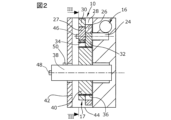
図2は、図1の駆動装置の側面図である。
図3は、駆動装置におけるトランスミッション装置の断面図である。
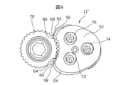
図4は、他の実施形態に係るトランスミッション装置の概略図である。
The present invention will be described below with reference to the drawings.
1 is a schematic diagram of a door mechanism with a drive; FIG.
2 is a side view of the drive device of FIG. 1; FIG.
FIG. 3 is a cross-sectional view of a transmission device in the drive system.
FIG. 4 is a schematic diagram of a transmission device according to another embodiment.
図1は、ドア機構2の概略図である。ここで、「ドア機構」の語は、開口部に対する閉鎖部材の一種を意味する。公知のように、ドア機構2はフレーム装置4を備え、このフレーム装置4においてゲート部材6が摺動可能に移動する構成とされている。駆動装置8は、フレーム構成4上に配置され、電気モータ10およびトランスミッション装置12を備える。駆動装置8は、これら電気モータ10およびトランスミッション装置12を用いてドアシャフト14を駆動し、ドア部材6を閉状態から開状態に、およびその逆へ移動できる。本発明を例示する実施形態において、電気モータ10は通常のDCモータである。電気モータ10には、トランスミッション16が公知の方法で接続される。トランスミッション16は、撓みのあるウォームギアとして、または撓みのない牽引ギアとして設計できる。本実施形態において、トランスミッション16と偏心ギアトランスミッション17とで、トランスミッション装置12を形成している。駆動装置8とトランスミッション装置12とは、フレーム装置4に対して公知の方法で強固に接続されたトルク支持体18上に設けられる。トランスミッション16が牽引ギアとして設計される場合には、駆動装置8をドアシャフト14から離れた位置に配置できる。また、駆動装置8のモータ駆動シャフト(図示しない)を、偏心ギアトランスミッション17に直接接続してもよい。
FIG. 1 is a schematic diagram of the
図1では、ドア部材6が中間位置に示されている。さらに、図1には、ケーブルを用いることなく、BluetoothやWLANを介して、電気モータ10、3Dセンサ20、および安全エッジ22に対して無線接続されるドア制御装置19が示されている。3Dセンサ20は、ドア部材6の周囲領域を非接触監視するために設けられる。安全エッジ22は、公知の方法で使用される障害物監視用の触覚式安全手段であり、ドア部材6が障害物に当たると移動を停止させる構成とされている。
In FIG. 1 the
図2は、図1の駆動装置8の部分断面図である。図2に図示しない電動モータ10は、トランスミッション16を介して、2つの偏心部26,27を有する偏心シャフト24として構成された駆動シャフト24に公知の方法で接続される。偏心部26,27は、互いに180°ずれた状態で位相変位して配置された2つの旋回歯付きディスク28,30に対して移動可能に取り付けられる。図3に詳細に示すとおり、歯付ディスク28,30は、それぞれ内歯32,34を有する。内歯32,34は、従動シャフト38に対して回転するように固定接続された第3歯付ディスク40の外歯36と係合する。従動シャフト38は、貫通中空シャフトとして設計可能で、ここでは概略的に図示している。トランスミッション装置16は、駆動装置8のハウジングの一部であり、歯付ディスク28,30の上方で壁部44と係合するカバー部分42にて閉じられている。
FIG. 2 is a partial cross-sectional view of the
図3は、歯付ディスク28の断面図である。図3には、歯付ディスク28と歯付ディスク40との係合状態が、非常に多数の歯にてなされることが示されている。この係合により、トルク伝達が確実に保証される。歯付ディスク28,30と歯付ディスク40との間の歯数の違いに応じ、駆動シャフト24から従動シャフト38へのギア比を調整できる。なお、伝達トルクを増加させるために、複数の偏心シャフトを有する複数の電気モータを使用してもよい。
FIG. 3 is a cross-sectional view of
駆動装置8およびドア機構2の機能性および安全性をさらに高めるために、例えば、偏心シャフト24および従動シャフト38に、ロータリエンコーダ46,48を設けてもよい。ロータリエンコーダ46,48は、制御の観点からドア制御装置19に接続されるため、駆動装置8の摩耗等を、その回転比の変化にて判定可能になる。また、例えば速度センサ50を従動シャフト38(図2を参照)に設け、障害物との衝突を検出する構成にしてもよい。その場合、図1に示す安全エッジ22を備えなくてもよい。さらに、温度センサ、振動センサ等のセンサを駆動装置8、特に電気モータ10の領域に設けて、電気モータ10および駆動装置8の異常を検出構成にしてもよい。
In order to further increase the functionality and safety of the
図4は、他の実施形態に係るトランスミッション装置12´の概略図である。トランスミッション装置12´は、3つの歯付ディスク52,54、56を備える。各歯付ディスク52,54,56は、それぞれ対応する外側58,60,62に部分リング状の内歯64,66,68を有している。図4では、ギア54のみが内歯66を介して従動シャフト70と係合している。歯付ディスク52,54,56は、3つの偏心シャフト72,74,76にて駆動される。
FIG. 4 is a schematic diagram of a transmission device 12' according to another embodiment. The transmission device 12' comprises three
Claims (13)
前記トランスミッション装置(12、12´)は、偏心ギアトランスミッション(17)を備え、
前記少なくとも1つの電動モータ(10)の少なくとも1つの偏心シャフト(24;72,74,76)にて駆動される少なくとも2つの旋回歯付ディスク(52,54,56)が、その外側(58,60,62)に設けられて、それぞれがピッチ円状に形成された内歯(64,66,68)を介して、前記ドアシャフト(14)に連結された従動シャフト(38、70)と係合する、
ことを特徴とする駆動装置。 At least one electric motor coupled to a transmission (12, 12') for driving a door shaft (14) for moving the door member (6) of the door mechanism (2) from closed to open and vice versa. A driving device for the door mechanism (2) having (10),
said transmission device (12, 12') comprises an eccentric gear transmission (17),
At least two pivoting toothed discs (52, 54 , 56) driven by at least one eccentric shaft (24; 72, 74, 76) of said at least one electric motor (10) are mounted on its outer side (58 , 60, 62) and connected to the door shaft (14) via internal teeth ( 64 , 66, 68) each formed in a pitch circle shape. engage with
A driving device characterized by:
ことを特徴とする請求項1に記載の駆動装置。 said toothed discs ( 52 , 54, 56) are arranged to be synchronous or phase-shifted;
The driving device according to claim 1, characterized in that:
ことを特徴とする請求項1または2に記載の駆動装置。 From a control point of view, a door controller (19) is provided which is connected to said at least one electric motor (10),
3. The driving device according to claim 1 or 2, characterized in that:
ことを特徴とする請求項3に記載の駆動装置。 said door controller (19) is operated or read wirelessly via WLAN or Bluetooth,
4. The driving device according to claim 3, characterized in that:
前記少なくとも1つのロータリエンコーダ(46)および前記少なくとも1つのロータリエンコーダ(48)は、制御の観点から、前記ドア制御装置(19)に接続される、
ことを特徴とする請求項3または4に記載の駆動装置。 at least one rotary encoder (46) on said eccentric shaft (24) and/or at least one rotary encoder (48) on said driven shaft (38, 70);
said at least one rotary encoder (46) and said at least one rotary encoder (48) are connected to said door controller (19) from a control point of view;
5. The driving device according to claim 3 or 4, characterized in that:
ことを特徴とする請求項3ないし4のいずれか一項に記載の駆動装置。 providing at least one speed sensor (50) on said driven shaft (38, 70);
5. The driving device according to any one of claims 3 to 4, characterized in that:
ことを特徴とする請求項4または5に記載の駆動装置。 further comprising a temperature sensor, a vibration sensor, a torque sensor and/or an ammeter in the area of the driving device (8);
6. The driving device according to claim 4 or 5, characterized in that:
ことを特徴とする請求項1ないし7のいずれか一項に記載の駆動装置。 the electric motor (14) is a DC motor,
8. The driving device according to any one of claims 1 to 7, characterized in that:
ことを特徴とする請求項1ないし8のいずれか一項に記載の駆動装置。 said at least two swivel-toothed discs ( 52 , 54, 56) are flexibly or rigidly connected to each other via connecting means;
9. The driving device according to any one of claims 1 to 8, characterized in that:
ことを特徴とする請求項1ないし9のいずれか一項に記載の駆動装置。 said electric motor (14) is connected to said eccentric gear transmission (17) via a traction gear;
10. The driving device according to any one of claims 1 to 9, characterized in that:
ことを特徴とする請求項1に記載の駆動装置。 three toothed discs (52, 54, 56) driven by three eccentric shafts (72, 74, 76) and pivoting in a phase-shifted manner with respect to each other are provided;
The driving device according to claim 1 , characterized in that:
前記ドア部材(6)用のフレーム装置(4)を備え、
前記フレーム装置(4)には、前記駆動装置(8)が配置される、
ことを特徴とするドア機構。 A door mechanism comprising a drive (8) according to any one of claims 1 to 11 ,
a frame device (4) for the door member (6);
The driving device (8) is arranged on the frame device (4),
A door mechanism characterized by:
前記ドア部材(6)用のフレーム装置(4)を備え、
前記フレーム装置(4)には、前記駆動装置(8)が配置され、
制御の観点から、前記ドア制御装置(19)に無線接続される、安全エッジ装置、ライトグリッド、3Dセンサのうち少なくとも何れかのセンサ装置をさらに備える、
ことを特徴とするドア機構。
A door mechanism comprising a drive (8) according to claim 3,
a frame device (4) for the door member (6);
The driving device (8) is arranged in the frame device (4),
From a control point of view, it further comprises a sensor device wirelessly connected to said door control device (19), a safety edge device, a light grid and/or a 3D sensor,
A door mechanism characterized by:
Applications Claiming Priority (3)
| Application Number | Priority Date | Filing Date | Title |
|---|---|---|---|
| DE102019107322.7A DE102019107322B4 (en) | 2019-03-21 | 2019-03-21 | Drive arrangement for a gate device and gate device |
| DE102019107322.7 | 2019-03-21 | ||
| PCT/EP2020/057333 WO2020187932A1 (en) | 2019-03-21 | 2020-03-17 | Drive arrangement for a door device, and door device |
Publications (2)
| Publication Number | Publication Date |
|---|---|
| JP2022525939A JP2022525939A (en) | 2022-05-20 |
| JP7302002B2 true JP7302002B2 (en) | 2023-07-03 |
Family
ID=70005599
Family Applications (1)
| Application Number | Title | Priority Date | Filing Date |
|---|---|---|---|
| JP2021556541A Active JP7302002B2 (en) | 2019-03-21 | 2020-03-17 | Door mechanism drive and door mechanism |
Country Status (6)
| Country | Link |
|---|---|
| US (1) | US12252934B2 (en) |
| EP (1) | EP3942139B1 (en) |
| JP (1) | JP7302002B2 (en) |
| CN (1) | CN113677866B (en) |
| DE (1) | DE102019107322B4 (en) |
| WO (1) | WO2020187932A1 (en) |
Families Citing this family (1)
| Publication number | Priority date | Publication date | Assignee | Title |
|---|---|---|---|---|
| DE102022124428B3 (en) | 2022-09-22 | 2024-02-15 | Fraba B.V. | Movement counter arrangement for a gate arrangement and gate arrangement |
Citations (4)
| Publication number | Priority date | Publication date | Assignee | Title |
|---|---|---|---|---|
| JP2000154689A (en) | 1998-11-20 | 2000-06-06 | Shibaura Densan Kk | Motor-driven roller device |
| JP2005036515A (en) | 2003-07-15 | 2005-02-10 | Aisin Seiki Co Ltd | Shutter winding drive device |
| US20100229665A1 (en) | 2007-10-26 | 2010-09-16 | Vishvas Prabhakar Ambardekar | Modified eccentric gearbox |
| JP2017179736A (en) | 2016-03-28 | 2017-10-05 | 文化シヤッター株式会社 | Opening/closing device, and opening/closing device monitoring system for monitoring the same |
Family Cites Families (20)
| Publication number | Priority date | Publication date | Assignee | Title |
|---|---|---|---|---|
| DE3428488A1 (en) * | 1984-08-02 | 1986-02-13 | Messerschmitt-Bölkow-Blohm GmbH, 8012 Ottobrunn | DEVICE FOR SUPPORTING THE SLEEVE IN PRESSING A HEAD LOAD |
| EP0551050B1 (en) * | 1992-01-10 | 1996-06-26 | AGINFOR AG für industrielle Forschung | Eccentric gearing |
| US5425683A (en) * | 1992-09-25 | 1995-06-20 | Bang; Yu A. | Single-ring-gear planetary transmisssion unit with small difference between teeth of meshing gears |
| US5423628A (en) * | 1994-06-28 | 1995-06-13 | M-B-W Inc. | Winch construction for a vibratory concrete screed |
| US6422965B1 (en) * | 2000-04-20 | 2002-07-23 | Overhead Door Corporation | Door operator unit |
| US8831970B2 (en) * | 2000-08-24 | 2014-09-09 | Martin Herman Weik, III | Virtual attendant system and parking management system |
| EP1426538B1 (en) | 2002-11-29 | 2011-05-18 | Hörmann KG Antriebstechnik | Shaft door drive system and door with such a drive system |
| EP1965018B1 (en) * | 2007-03-02 | 2014-07-30 | Hörmann Kg Dissen | Door with tension spring compensation and drive device for this purpose |
| US20110092332A1 (en) * | 2008-05-02 | 2011-04-21 | Evenson Roger A | Compact backdrive resistant transmission |
| US8692498B2 (en) * | 2010-08-30 | 2014-04-08 | Crestron Electronics Inc. | System and method for controlling one or more roller shades |
| EP2677197A4 (en) | 2011-02-14 | 2014-09-03 | Toshiaki Shimada | Gear device and drive device |
| US10655386B2 (en) * | 2011-03-11 | 2020-05-19 | Lutron Technology Company Llc | Motorized window treatment |
| US20130112357A1 (en) * | 2011-11-04 | 2013-05-09 | Rytec Corporation | Overhead Roll-Up Door Having At Least Two Motors |
| DE102012106889A1 (en) * | 2012-07-30 | 2014-01-30 | Fraba N.V. | Monitoring and control device for a gate unit |
| CN204343959U (en) * | 2014-12-17 | 2015-05-20 | 第一传动科技股份有限公司 | Iron rolling door retracting device |
| DE102015101248B4 (en) | 2015-01-28 | 2024-12-12 | Fraba B.V. | magnet-based angle measuring system |
| DE102015107416B4 (en) * | 2015-05-12 | 2018-08-30 | Fraba B.V. | Maintenance system for monitoring a gate device and method for monitoring a gate device |
| CN105909162A (en) * | 2016-05-01 | 2016-08-31 | 平阳微体日用品有限公司 | Rolling gate |
| CN206000338U (en) * | 2016-08-05 | 2017-03-08 | 昆山麦格纳汽车系统有限公司 | Door opening machine of garage |
| DE102017126124A1 (en) * | 2017-07-07 | 2019-01-10 | Hörmann KG Antriebstechnik | Door drive device with gate leaf position detection device |
-
2019
- 2019-03-21 DE DE102019107322.7A patent/DE102019107322B4/en active Active
-
2020
- 2020-03-17 US US17/440,797 patent/US12252934B2/en active Active
- 2020-03-17 WO PCT/EP2020/057333 patent/WO2020187932A1/en not_active Ceased
- 2020-03-17 CN CN202080021845.2A patent/CN113677866B/en active Active
- 2020-03-17 JP JP2021556541A patent/JP7302002B2/en active Active
- 2020-03-17 EP EP20714149.0A patent/EP3942139B1/en active Active
Patent Citations (4)
| Publication number | Priority date | Publication date | Assignee | Title |
|---|---|---|---|---|
| JP2000154689A (en) | 1998-11-20 | 2000-06-06 | Shibaura Densan Kk | Motor-driven roller device |
| JP2005036515A (en) | 2003-07-15 | 2005-02-10 | Aisin Seiki Co Ltd | Shutter winding drive device |
| US20100229665A1 (en) | 2007-10-26 | 2010-09-16 | Vishvas Prabhakar Ambardekar | Modified eccentric gearbox |
| JP2017179736A (en) | 2016-03-28 | 2017-10-05 | 文化シヤッター株式会社 | Opening/closing device, and opening/closing device monitoring system for monitoring the same |
Also Published As
| Publication number | Publication date |
|---|---|
| JP2022525939A (en) | 2022-05-20 |
| DE102019107322A1 (en) | 2020-09-24 |
| DE102019107322B4 (en) | 2020-10-22 |
| US20220162909A1 (en) | 2022-05-26 |
| WO2020187932A1 (en) | 2020-09-24 |
| EP3942139A1 (en) | 2022-01-26 |
| CN113677866A (en) | 2021-11-19 |
| CN113677866B (en) | 2023-03-07 |
| EP3942139B1 (en) | 2025-12-10 |
| US12252934B2 (en) | 2025-03-18 |
Similar Documents
| Publication | Publication Date | Title |
|---|---|---|
| RU2429334C1 (en) | Driving system for turned and/or displaced doors or for entrance/exit device with improved position measurement | |
| JP5379903B2 (en) | Method and system for monitoring a movable partition | |
| US20080047200A1 (en) | Door drive for an automatic door | |
| US20090308701A1 (en) | Actuator with function monitor | |
| JP7302002B2 (en) | Door mechanism drive and door mechanism | |
| CN105448554B (en) | A kind of wide-angle output motor operating mechanism | |
| EP3219898B1 (en) | Battery powered winding shaft for a roller blind | |
| JP6808474B2 (en) | Absolute encoder for motor with gear | |
| KR20180036990A (en) | A drive for the rotatable wing | |
| CN111692326B (en) | Driving device, robot, and image forming apparatus | |
| US20180045261A1 (en) | Rotary drive device comprising load-dependent brakes | |
| CN207603395U (en) | Actuator module | |
| JP7021220B2 (en) | A gate with a collapse prevention mechanism and a method of triggering a collapse prevention mechanism | |
| JP3142139U (en) | Position limit type horizontal curtain | |
| WO2009117692A2 (en) | Position sensor and method | |
| US9822575B2 (en) | Movable body driving device | |
| CN111156344A (en) | Angle stroke transmission device of positive and negative automatic gear hanging | |
| KR20170062814A (en) | Blade adjusting device for volume damper | |
| CN109695682A (en) | A kind of electromechanical actuator | |
| US11993972B2 (en) | Universal rotary actuators | |
| JP5043566B2 (en) | Elevator equipment | |
| CN116241612A (en) | A single-input and multi-output transmission structure and its application | |
| KR20190011633A (en) | Apparatus for measuring rotation angle | |
| JP2024007062A (en) | actuator system | |
| KR20220099563A (en) | Actuator device for gearbox |
Legal Events
| Date | Code | Title | Description |
|---|---|---|---|
| A521 | Request for written amendment filed |
Free format text: JAPANESE INTERMEDIATE CODE: A523 Effective date: 20211130 |
|
| A621 | Written request for application examination |
Free format text: JAPANESE INTERMEDIATE CODE: A621 Effective date: 20211115 |
|
| A977 | Report on retrieval |
Free format text: JAPANESE INTERMEDIATE CODE: A971007 Effective date: 20220927 |
|
| A131 | Notification of reasons for refusal |
Free format text: JAPANESE INTERMEDIATE CODE: A131 Effective date: 20221004 |
|
| A521 | Request for written amendment filed |
Free format text: JAPANESE INTERMEDIATE CODE: A523 Effective date: 20221212 |
|
| A131 | Notification of reasons for refusal |
Free format text: JAPANESE INTERMEDIATE CODE: A131 Effective date: 20230117 |
|
| A521 | Request for written amendment filed |
Free format text: JAPANESE INTERMEDIATE CODE: A523 Effective date: 20230417 |
|
| TRDD | Decision of grant or rejection written | ||
| A01 | Written decision to grant a patent or to grant a registration (utility model) |
Free format text: JAPANESE INTERMEDIATE CODE: A01 Effective date: 20230613 |
|
| A61 | First payment of annual fees (during grant procedure) |
Free format text: JAPANESE INTERMEDIATE CODE: A61 Effective date: 20230621 |
|
| R150 | Certificate of patent or registration of utility model |
Ref document number: 7302002 Country of ref document: JP Free format text: JAPANESE INTERMEDIATE CODE: R150 |