JP2012505306A - Method for producing a part comprising a block of cemented carbide type high density material having a characteristic gradient and the resulting part - Google Patents
Method for producing a part comprising a block of cemented carbide type high density material having a characteristic gradient and the resulting part Download PDFInfo
- Publication number
- JP2012505306A JP2012505306A JP2011529611A JP2011529611A JP2012505306A JP 2012505306 A JP2012505306 A JP 2012505306A JP 2011529611 A JP2011529611 A JP 2011529611A JP 2011529611 A JP2011529611 A JP 2011529611A JP 2012505306 A JP2012505306 A JP 2012505306A
- Authority
- JP
- Japan
- Prior art keywords
- block
- binder phase
- temperature
- density material
- cemented carbide
- Prior art date
- Legal status (The legal status is an assumption and is not a legal conclusion. Google has not performed a legal analysis and makes no representation as to the accuracy of the status listed.)
- Granted
Links
Images


Classifications
-
- C—CHEMISTRY; METALLURGY
- C22—METALLURGY; FERROUS OR NON-FERROUS ALLOYS; TREATMENT OF ALLOYS OR NON-FERROUS METALS
- C22C—ALLOYS
- C22C29/00—Alloys based on carbides, oxides, nitrides, borides, or silicides, e.g. cermets, or other metal compounds, e.g. oxynitrides, sulfides
- C22C29/02—Alloys based on carbides, oxides, nitrides, borides, or silicides, e.g. cermets, or other metal compounds, e.g. oxynitrides, sulfides based on carbides or carbonitrides
- C22C29/06—Alloys based on carbides, oxides, nitrides, borides, or silicides, e.g. cermets, or other metal compounds, e.g. oxynitrides, sulfides based on carbides or carbonitrides based on carbides, but not containing other metal compounds
- C22C29/08—Alloys based on carbides, oxides, nitrides, borides, or silicides, e.g. cermets, or other metal compounds, e.g. oxynitrides, sulfides based on carbides or carbonitrides based on carbides, but not containing other metal compounds based on tungsten carbide
-
- Y—GENERAL TAGGING OF NEW TECHNOLOGICAL DEVELOPMENTS; GENERAL TAGGING OF CROSS-SECTIONAL TECHNOLOGIES SPANNING OVER SEVERAL SECTIONS OF THE IPC; TECHNICAL SUBJECTS COVERED BY FORMER USPC CROSS-REFERENCE ART COLLECTIONS [XRACs] AND DIGESTS
- Y10—TECHNICAL SUBJECTS COVERED BY FORMER USPC
- Y10T—TECHNICAL SUBJECTS COVERED BY FORMER US CLASSIFICATION
- Y10T428/00—Stock material or miscellaneous articles
- Y10T428/12—All metal or with adjacent metals
- Y10T428/12014—All metal or with adjacent metals having metal particles
- Y10T428/12028—Composite; i.e., plural, adjacent, spatially distinct metal components [e.g., layers, etc.]
- Y10T428/12049—Nonmetal component
Abstract
バインダー相中に分散させた同じ又は異なるタイプの硬質粒子で構成され、上記バインダー相が液体である温度から始まる固相線温度Tsを有する高密度材料のブロック(1)を含む部分を製造するための方法であって、高密度材料の上記ブロック(1)の表面の少なくとも一部分に、全体を最低反応温度Tr超にしたときに上記高密度材料と化学的に反応可能な材料で構成された活性被膜(2)を被着させ、上記活性被膜(2)をコーティングした上記ブロック(1)を、加熱、次いで上記最低反応温度Tr以上の保持温度Tmまでの時間tmの間の保持、続いて大気温度までの冷却を含む熱処理にかけることを特徴とし、外部からのバインダー相を加えることなく、したがって追加のバインダー相中の上記ブロックの全体的な強化を起こさずに実施され、ミリメートルの距離にわたる上記ブロック内の上記バインダー相の変形形態をもたらす、方法。
【選択図】図1Producing a part comprising a block (1) of high-density material composed of hard particles of the same or different types dispersed in a binder phase and having a solidus temperature T s starting from the temperature at which the binder phase is liquid For at least a portion of the surface of the block (1) of high-density material made of a material that can chemically react with the high-density material when the entire temperature exceeds the minimum reaction temperature Tr. The active film (2) is applied and the block (1) coated with the active film (2) is heated, and then during a time t m to a holding temperature T m above the minimum reaction temperature T r . It is characterized by subjecting it to a heat treatment including holding and subsequent cooling to ambient temperature, and without adding an external binder phase, and thus the overall strengthening of the block in the additional binder phase. Is carried out without straining, resulting in a variation of the binder phase in the block over a distance of millimeters, methods.
[Selection] Figure 1
Description
熱化学処理によってバインダー相中に分散させた硬質粒子で構成された高密度材料のブロックを含み、特性勾配を有する部分を製造するための方法である。 A method for producing a part having a characteristic gradient comprising a block of high density material composed of hard particles dispersed in a binder phase by thermochemical treatment.
多くの部分、特に穴あけ工具又は機械加工工具の刃先は、金属バインダー相中に分散させた炭化物粒子で構成された超硬合金型の材料で作られたブロックで構成されている。極めて硬く、したがって耐摩耗性があるこれらの材料は、脆いこともある。また、材料の破壊靭性を強化するため、外面若しくはこの表面の少なくとも一部分が極めて硬く、且つ内部がより堅いブロック、又は外面若しくは少なくとも一部分がより堅く、且つ内部がより硬いブロックをもたらす、硬度がブロックの初めの硬度と異なる新しい相を形成して、又は形成することなく、延性相中の組成勾配の範囲内で導入するための処理を材料に施す。 Many parts, especially the cutting edges of drilling tools or machining tools, are made up of blocks made of cemented carbide type material made up of carbide particles dispersed in a metal binder phase. These materials that are extremely hard and therefore wear resistant can be brittle. Also, to enhance the fracture toughness of the material, the hardness is a block that results in a block that is extremely hard on the outer surface or at least part of this surface and that is harder on the inside, or a block that is harder on the outer surface or at least part and harder on the inside The material is subjected to a treatment to be introduced within the composition gradient in the ductile phase, with or without the formation of a new phase different from the initial hardness.
それには、粉末冶金によって実施でき、且つブロックの中心部の延性を改善するためにバインダー相を浸潤させた、気孔率勾配を有する、高密度ではない超硬合金のブロックを製造することができる。この方法は、特にWC−Co型の系にはあまり適合しない。なぜならば、この方法は、浸潤前に存在した炭化物の骨格構造の部分的な破壊をもたらし、したがって、刃先の所望の特性が得られないからである。 This can be done by powder metallurgy and can produce a non-dense cemented carbide block with a porosity gradient infiltrated with a binder phase to improve the ductility of the center of the block. This method is not particularly well suited for WC-Co type systems. This is because this method results in partial destruction of the carbide skeletal structure present prior to infiltration and thus the desired properties of the cutting edge cannot be obtained.
それぞれの層が異なる組成を有する多層部分を含む固相内に、自然焼結によって組成勾配をもつ超硬合金を達成することも提案されている。しかしながら、この方法は、材料を十分に緻密化させることができず、費用のかかる熱間等方圧圧縮(hot isotactic compaction)処理を続いて行わなければならない。さらに、組成勾配をもつ超硬合金の調製は複雑である。その理由は、互いに重ね合わさった(nest)連続する基本層を実現する必要があるからである。最後に、この方法は、連続的な組成勾配を生成しないという欠点がある。 It has also been proposed to achieve a cemented carbide with a composition gradient by natural sintering in a solid phase comprising multiple layers, each layer having a different composition. However, this method does not allow the material to be fully densified and must be followed by an expensive hot isostatic compression process. Furthermore, the preparation of cemented carbide with a composition gradient is complex. This is because it is necessary to realize a base layer that is continuous with each other. Finally, this method has the disadvantage of not producing a continuous composition gradient.
液相内の自然焼結によってかかる材料を達成することも提案されており、これは極めて迅速に、且つ単一ステップで、完全に緻密な組成勾配を有する材料を得ることを可能にする。しかし、この方法は、浸潤及び膨潤現象の複合効果の下、厚さが小さい層の間の液体が移動するため、かなり実質的に組成勾配が少なくなる欠点がある。さらに、全く予期に反して、組成勾配は、液体状態に保つ期間が臨界期間よりも短いままである場合、不連続なままであり、この臨界期間を超えると超硬合金の完全な均質化が認められるが、材料を緻密化するのに不十分である。 It has also been proposed to achieve such materials by natural sintering in the liquid phase, which makes it possible to obtain a material with a completely dense composition gradient very quickly and in a single step. However, this method has a drawback that the composition gradient is considerably reduced because the liquid moves between the layers having a small thickness under the combined effect of the infiltration and swelling phenomenon. Furthermore, quite unexpectedly, the composition gradient remains discontinuous if the period of staying in the liquid state remains shorter than the critical period, beyond which the homogenization of the cemented carbide becomes complete. It is recognized that it is insufficient to densify the material.
その上、超硬合金の表面に窒化物、炭窒化物、酸化物又はホウ化物でできた硬質被膜を被着させることによって、切削工具の使用性能を改善することが提案されている。このような方法は、例えば、米国特許第4548786号明細書又は同第4610931号明細書に記載されている。しかし、これらの方法は、超硬合金の研磨によって耐摩耗性を改善するだけであり、この改善は小さい厚さ(数ミクロン)に対してだけであるという欠点がある。 Moreover, it has been proposed to improve the performance of the cutting tool by depositing a hard coating made of nitride, carbonitride, oxide or boride on the surface of the cemented carbide. Such a method is described, for example, in US Pat. No. 4,548,786 or US Pat. No. 4,610,931. However, these methods have the disadvantage that they only improve the wear resistance by grinding cemented carbide, and this improvement is only for small thicknesses (several microns).
炭素が多量な気相を炭素に関して準化学量論的な高密度超硬合金と接触させることによって、WC−Co型の超硬合金の表面の耐摩耗性並びに耐衝撃性を改善することも提案されている。温度の影響下では、気相の炭素が準化学量論的な超硬合金内に拡散し、且つη−CO3W3C相と反応してコバルトの放出をもたらし、このコバルトは、超硬合金の外面、すなわち炭素の前面の拡散の背面に向かって移動する。米国特許第4743515号明細書に記載されているこの方法は、1又は2mmにわたってコバルトが多量なバインダー相勾配をもたらすが、処理した部分の中心部の脆弱性を保ったままであるという欠点がある。 It is also proposed to improve the wear resistance and impact resistance of the surface of WC-Co type cemented carbide by contacting the gas phase rich in carbon with a substoichiometric high density cemented carbide with respect to carbon. Has been. Under the influence of temperature, the vapor phase carbon diffuses into the substoichiometric cemented carbide and reacts with the η-CO 3 W 3 C phase, leading to the release of cobalt, which is It moves towards the outer surface of the alloy, ie the back of the diffusion of the front of the carbon. This method described in U.S. Pat. No. 4,743,515 has the disadvantage that cobalt leads to a large binder phase gradient over 1 or 2 mm, but remains centrally fragile in the treated part.
上述の方法の種々の欠点を改善するために、超硬合金中に侵入(又は移動)可能な液相を用いて、外部から膨潤によってこれらの超硬合金を強化することによって、ミリメートルの距離にわたってバインダー相中に組成勾配を有する超硬合金のブロックを製造することが提案されている。この膨潤現象は、固体/液体系の組成に近い組成の外部液体の移動に対応しており、バインダー相の体積分率並びに/又は固体粒子の大きさ及び形態の局所的不均衡によってもたらされた移動の圧力の単独の推進力下で完全に緻密であると考えられている。この現象は、液体の吸収によりその固体粒子の形態を適合させる能力を有しており、したがってエネルギー的に安定にし、すなわち、溶解と再沈殿現象によってこれらの粒子の大きさを必ずしも増大させることなく、硬質粒子の形態の変更によってオストワルド熱成(Ostwald ripening)を有する、凝縮相(固体及び液体)で構成された任意の系に関する。 In order to remedy the various drawbacks of the above-described method, over a distance of millimeters by strengthening these cemented carbides by swelling from the outside with a liquid phase that can penetrate (or move) into the cemented carbides. It has been proposed to produce cemented carbide blocks having a composition gradient in the binder phase. This swelling phenomenon corresponds to the movement of an external liquid with a composition close to that of the solid / liquid system and is caused by a local imbalance in the volume fraction of the binder phase and / or the size and form of the solid particles. It is considered to be perfectly dense under the sole driving force of the moving pressure. This phenomenon has the ability to adapt the morphology of its solid particles by absorption of liquids, thus making it energetically stable, i.e. without necessarily increasing the size of these particles by dissolution and reprecipitation phenomena. Relates to any system composed of condensed phases (solid and liquid), having Ostwald ripening by changing the morphology of the hard particles.
穴あけ工具又は切削工具用の刃先を製造するためのこの方法の使用は、強化させるよう意図されている焼結高密度ブロックと、膨潤現象によってバインダー相を供給するよう意図されている膨潤材料が加圧された粉末ペレットとのより重要なアセンブリの達成、並びに十分な熱処理を実施するための全体の炉内への配置を必要とする。この方法には、所望の組成勾配に関して必要な大きさにしなければならない膨潤材料を要求する欠点があり、この欠点はこの方法を複雑にし、ほとんどの場合膨潤表面の修正を要する。 The use of this method to produce cutting edges for drilling tools or cutting tools involves the addition of a sintered dense block intended to be strengthened and a swollen material intended to supply the binder phase by means of swelling phenomena. It requires the achievement of a more important assembly with the pressed powder pellets as well as the placement in the whole furnace in order to carry out a sufficient heat treatment. This method has the disadvantage of requiring a swollen material that must be sized as required for the desired composition gradient, which complicates the method and in most cases requires modification of the swollen surface.
極めて意外な方法で、本発明者らは、高密度超硬合金ブロック内にミリメートルの距離にわたってバインダー相中に濃度勾配をもたらすことが可能だったことを発見し、唯一の条件は、適合被膜を高密度超硬合金ブロックの表面のすべて又は一部分に被着させ、且つ十分な熱処理を施すことであり、熱処理の温度は、バインダー相の液体状態への移行を可能にする温度(考慮中の超硬合金の固相線)と少なくとも同じでなければならない。 In a very surprising way, we discovered that it was possible to produce a concentration gradient in the binder phase over a distance of millimeters in a high density cemented carbide block, the only condition being It is applied to all or part of the surface of the high-density cemented carbide block and is subjected to a sufficient heat treatment, and the temperature of the heat treatment is the temperature that allows the binder phase to transition to the liquid state (the ultra It must be at least the same as the solidus) of the hard alloy.
被膜を構成する材料は、不安定化されており(又は分離されており)、材料を構成する1つ又は複数の化学元素は、拡散し、且つブロックの材料と反応し、又は反応せず、ブロック中のバインダー相勾配の生成及び/又は適用した熱処理の持続期間に応じた、おおよそ実質的な距離にわたって硬度がブロックの初めの硬度と異なる相の形成をもたらす。ブロック中にそのように生成した勾配の形態、すなわち、被膜を被着させた表面の硬化、中心部の軟化又は被膜を適用した表面の逆の軟化、及び中心部の硬化は、使用した被膜の性質及び厚さ、コーティングした表面の割合及び熱処理に特に依存する。熱処理のパラメーターは、特に所望の勾配の形態に応じて当業者によって決定することができる。 The material making up the coating is destabilized (or separated), and one or more chemical elements that make up the material diffuse and react or do not react with the block material, Depending on the generation of the binder phase gradient in the block and / or the duration of the heat treatment applied, this results in the formation of a phase whose hardness differs from the initial hardness of the block over a substantial distance. The form of the gradient so generated during the block, i.e. the hardening of the surface to which the coating is applied, the softening of the center or the reverse softening of the surface to which the coating has been applied, and the hardening of the center are dependent on the coating used. It depends in particular on the nature and thickness, the proportion of the coated surface and the heat treatment. The parameters of the heat treatment can be determined by a person skilled in the art depending in particular on the desired form of gradient.
これらの発見を踏まえて、熱処理を実施する前にサーメットの表面上に被着させ得る材料を、以下の種類に分けることができる。すなわち、
高密度ブロックを含む不活性な材料:上記材料は、高密度ブロック中にマクロスケールでバインダー相の任意の局所的な変形形態を生まない材料を必要とする;
高密度ブロックを含む活性な材料:上記材料は、高密度ブロック中にマクロスケールでバインダー相の局所的な変形形態を生む材料を必要とする。このように、「活性な」という用語は、この方法に関して考えるべきであり、すなわち高密度ブロック中のバインダー相の局所的な変形形態をもたらすことである。
Based on these findings, the materials that can be deposited on the surface of the cermet before carrying out the heat treatment can be divided into the following types. That is,
Inert material comprising a dense block: The material requires a material that does not produce any local deformation of the binder phase on a macro scale in the dense block;
Active material comprising a high density block: The material requires a material that produces a localized deformation of the binder phase on a macro scale in the high density block. Thus, the term “active” should be considered with respect to this method, ie to bring about a local deformation of the binder phase in the dense block.
活性な材料のうち、以下を区別することができる:
追加のバインダー相を供給できるもの、及び
追加のバインダー相を全く供給できないもの。
Among the active materials, the following can be distinguished:
Those that can supply additional binder phase and those that cannot supply additional binder phase at all.
以下も区別する:
高密度ブロックを含む、活性な及び非反応性の(又は化学的に反応しにくい)材料:上記材料の化学元素は拡散するが、固相を全く形成しない高密度サーメットの2相(固体又は液体)のうちの1相と反応しないものである;及び
高密度ブロックを含む活性な及び化学的に反応性の材料:少なくとも1つの固相を形成する高密度サーメットの固相又は液相を介して、上記材料のいくつかの化学元素は拡散し、反応するものである。
Also distinguish:
Active and non-reactive (or chemically insensitive) materials, including high density blocks: two phases of solid cermets (solid or liquid) that diffuse the chemical elements of the material but do not form any solid phase Active and chemically reactive materials comprising a high density block: via a solid or liquid phase of a high density cermet that forms at least one solid phase. Some chemical elements of the above materials diffuse and react.
したがって、本発明は、目的に対し、バインダー相中に分散させた同じ性質又は異なる性質の硬質粒子で構成され、上記バインダー相が液体である温度から始まる固相線温度Tsを有する高密度材料のブロックを含む部分を製造するための方法であって、高密度材料のブロックの表面の少なくとも一部分に、全体を最低反応温度Tr超にしたときに高密度材料と化学的に反応可能であるが任意の追加のバインダー相を与えない材料で構成された活性被膜を被着させること、及び活性被膜をコーティングしたブロックを、加熱、次いで最低反応温度Tr以上の保持温度Tmで時間tmの間の保持、続いて大気温度までの冷却を含む熱処理にかけることを特徴とする方法を提供する。この方法は、外部からのバインダー相を加えることなく、したがって追加のバインダー相のブロックの全体的な強化(enrichment)を生じさせずに作製される、ミリメートルの距離にわたるブロック内のバインダー相の変形形態をもたらす。 Therefore, for the purpose of the present invention, a high-density material composed of hard particles of the same or different properties dispersed in a binder phase and having a solidus temperature T s starting from the temperature at which the binder phase is liquid. A method for producing a portion including a block of the material, wherein at least a part of the surface of the block of the high-density material can chemically react with the high-density material when the entire temperature exceeds the minimum reaction temperature Tr. Applying an active coating composed of a material that does not give any additional binder phase, and heating the block coated with the active coating, followed by a time t m at a holding temperature T m above the minimum reaction temperature T r The method is characterized in that it is subjected to a heat treatment comprising holding between, followed by cooling to ambient temperature. This method is a variation of the binder phase within the block over a distance of millimeters that is made without the addition of an external binder phase and thus without causing the overall enhancement of the block of additional binder phase. Bring.
保持温度Tmは、高密度材料の固相線温度Ts以上であることがより好ましい。 Holding temperature T m is more preferably solidus temperature T s or more dense material.
保持温度Tmは、Ts+200℃以下であることがより好ましい。 The holding temperature T m is more preferably T s + 200 ° C. or lower.
保持時間tmは、1分〜10分であることがより好ましい。 The holding time t m is more preferably 1 minute to 10 minutes.
活性被膜は、ブロックの表面の一部分にだけ被着させることができる。 The active coating can be applied only to a portion of the surface of the block.
活性被膜は、ブロックの表面全体に被着させることができる。 The active coating can be applied to the entire surface of the block.
高密度材料は、例えば、金属マトリックス中に分散させた金属炭化物粒子で構成された超硬合金である。 The high density material is, for example, a cemented carbide composed of metal carbide particles dispersed in a metal matrix.
超硬合金は、さらに、大きさが直径1mm以下の天然又は合成ダイヤモンド粒子を含有していてもよい。 The cemented carbide may further contain natural or synthetic diamond particles having a diameter of 1 mm or less.
超硬合金は、例えば、WC−M型であり、Mは、Co、Ni及びFeの中から選ばれる1種又は複数種の金属であり、バインダー相中のこれらの金属の含有率の合計は重量で、50%よりも高い。 The cemented carbide is, for example, WC-M type, and M is one or more metals selected from Co, Ni, and Fe, and the total content of these metals in the binder phase is Higher than 50% by weight.
ブロックの高密度材料と反応できる被膜材料は、例えば、窒化物、ホウ化物、炭化物、酸化物、水素化物、炭窒化物、ホウ炭化物、グラファイト型の化合物の中から選ばれる少なくとも1種の化合物で構成されている。この材料は、これらの種々の化合物の任意の混合物から構成され得る。 The coating material capable of reacting with the high density material of the block is, for example, at least one compound selected from nitride, boride, carbide, oxide, hydride, carbonitride, borocarbide, and graphite type compounds. It is configured. This material can be composed of any mixture of these various compounds.
被膜は、PVD(物理蒸着法)若しくはCVD(化学蒸着)型の方法、又は噴霧による若しくはブラシを用いた若しくは浸漬による若しくは連続撮影による方法によって被着させることができる。 The coating can be applied by PVD (Physical Vapor Deposition) or CVD (Chemical Vapor Deposition) type methods, or by spraying, using brushes, by dipping or by continuous photography.
高密度材料のブロックは、例えば、刃先、又は岩石若しくは金属用の穴あけ、破壊若しくは機械加工工具の刃先のブロック支持体である。 The block of high density material is, for example, a block support for the cutting edge of a cutting edge or a drilling, breaking or machining tool for rock or metal.
さらに、PDC(多結晶ダイヤモンド成形体)又はTSP(熱安定多結晶ダイヤモンド)型のダイヤモンドで被覆されたプレートは、ブロック支持体の表面上に被着させることができる。 Furthermore, a plate coated with PDC (polycrystalline diamond compact) or TSP (thermally stable polycrystalline diamond) type diamond can be deposited on the surface of the block support.
ダイヤモンドで被覆されたプレートは、ろう付によって、ブロックの処理後にブロックに加えることができる。 The diamond coated plate can be added to the block after processing the block by brazing.
このとき、この加熱法は穴あけ工具若しくは切削工具用の刃先として、又は穴あけ工具若しくは切削工具の刃先用のブロック支持体としての使用に適合した特性の勾配を有する超硬合金のブロックを非常に簡単な方法で達成する利点がある。 At this time, this heating method makes it very easy to make a cemented carbide block with a characteristic gradient suitable for use as a cutting edge for a drilling tool or cutting tool or as a block support for a cutting tool or cutting tool edge. There are advantages to achieve in a simple way.
本発明はさらに、本発明に基づく方法によって得ることができるバインダー相中に分散させた硬質粒子で構成されたブロックを含み、且つ0.5mm超、好ましくは1mm超、より好ましくは3mm超の長さにわたってバインダー相中の含有率の連続的な勾配を有し、最も多量な領域と最も少量な領域の間のバインダー相の含有率の差が体積で1%超、好ましくは2%超、より好ましくは5%超である、岩石を削るための工具用の刃先に関する。 The invention further comprises a block composed of hard particles dispersed in a binder phase obtainable by the process according to the invention and has a length of more than 0.5 mm, preferably more than 1 mm, more preferably more than 3 mm. With a continuous gradient of the content in the binder phase over which the difference in the content of the binder phase between the most abundant regions and the least abundant regions is more than 1% by volume, preferably more than 2%, more It relates to a cutting edge for a tool for cutting rock, preferably more than 5%.
刃先は、厚さが0.4mm〜5mmであってもよい、PDC又はTSP型の、追加のダイヤモンドで被覆されたプレートを含むことができる。 The cutting edge can include an additional diamond-coated plate of PDC or TSP type, which can be 0.4 mm to 5 mm in thickness.
本発明はさらに、少なくとも1種の刃先又は超硬合金と天然若しくは合成ダイヤモンド粒子(直径1mmに達し得る大きさを有する)との混合物で構成された含浸ブレードを含む、岩石を削るための工具に関する。 The invention further relates to a tool for cutting rock, comprising an impregnation blade composed of a mixture of at least one cutting edge or cemented carbide and natural or synthetic diamond particles (having a size that can reach a diameter of 1 mm). .
本発明は次に、添付図に関してより詳細だが制限しない形で説明するものとする。 The present invention will now be described in more detail but not with reference to the accompanying drawings.
以下において、寸法が数ミリメートル又は数十ミリメートルの長さの、一般に平行六面体形状又は円柱形状の、穴あけ工具用又はより一般に切削工具用の刃先を特に製造するためのブロックを考慮する。粉末冶金によって得られたこれらのブロックは、一方では金属炭化物、特に炭化タングステンなどの硬質粒子を含み、他方では主に金属又は合金で構成されたバインダー相を含む構造を有する高密度材料で構成されている。炭化物と接触すると、このバインダー相は、適合温度で、その融解温度が炭化物の融解温度未満であり、金属又は合金の融解温度未満である共晶を形成し得る。バインダー相を構成するこの金属又はこの合金は、例えばコバルトであるが、鉄又はニッケル又はこれらの金属の混合物であってもよく、これらの元素はバインダー相の少なくとも50重量%であることが典型である。 In the following, a block for producing a cutting edge for a drilling tool or more generally for a cutting tool, in particular of a parallelepiped shape or a cylindrical shape, of a length of a few millimeters or a few tens of millimeters will be considered. These blocks obtained by powder metallurgy are composed of high-density materials with a structure containing on the one hand hard particles such as metal carbides, in particular tungsten carbide, and on the other hand a binder phase composed mainly of metals or alloys. ing. Upon contact with the carbide, the binder phase can form a eutectic whose compatibility temperature is below the melting temperature of the carbide and below the melting temperature of the metal or alloy. This metal or this alloy constituting the binder phase is, for example, cobalt, but may be iron or nickel or a mixture of these metals, these elements typically being at least 50% by weight of the binder phase. is there.
このバインダー相は、合金添加物を含有していてもよく、その含有率の合計は、高くて15重量%に達することができるが、一般に5%を超えない。これらの合金添加物は、導電性を改善するために、銅、又は炭化物によって及びバインダー相によって構成された系に関して表面活性効果を有するケイ素とすることができる。合金添加物は、炭化物形成元素であってもよく、上記炭化物形成元素は混合炭化物又は炭化タングステン以外のMxCy型の炭化物の形成を可能にする。これらの元素は、特にマンガン、クロム、モリブデン、バナジウム、ニオブ、タンタル、チタン、ジルコニウム及びハフニウムである。 The binder phase may contain alloy additives, the total content of which can be as high as 15% by weight, but generally does not exceed 5%. These alloy additives can be copper, or silicon with a surface active effect on the system constituted by the carbides or by the binder phase in order to improve the conductivity. The alloy additive may be a carbide forming element, which enables the formation of M x C y type carbides other than mixed carbide or tungsten carbide. These elements are in particular manganese, chromium, molybdenum, vanadium, niobium, tantalum, titanium, zirconium and hafnium.
さらに、バインダー相は、硬質粒子の形状を変える合金添加物及び/又は成長を妨げる合金添加物、及び当業者に既知の合金添加物を含むことができる。 In addition, the binder phase can include alloy additives that change the shape of the hard particles and / or alloy additives that prevent growth, and alloy additives known to those skilled in the art.
最後に、これらの材料の化学成分には、合成の方法の結果として生じる不可避の不純物が含まれる。 Finally, the chemical components of these materials include inevitable impurities that arise as a result of the method of synthesis.
いくつかの用途のためには、刃先の耐摩耗性を強化するため、直径が1mmに達し得る天然又は合成ダイヤモンド粒子を加えることができる。これらのダイヤモンド粒子は、含浸という名前で知られている焼結によるブロックの製造に使用されている粉末混合物に加えられる。 For some applications, natural or synthetic diamond particles that can reach 1 mm in diameter can be added to enhance the wear resistance of the cutting edge. These diamond particles are added to a powder mixture that is used in the production of blocks by sintering, known as impregnation.
本発明によれば、特性勾配をもつ超硬合金のブロックを達成するためには、高密度材料のブロック1を、高密度材料のバインダー相及び/又は炭化物相と化学的に反応し得る材料の、厚さが一般に約50μm〜2mmの層2でコーティングする。このコーティングは、この被膜材料を気体形状で加える場合、噴霧、PVD(物理蒸着法)又はCVD(化学蒸着)被着によって実施され、或いは被膜材料を液体形状で加える場合、ブラシを用いて、浸漬又は連続撮影によって実施される。次いで全体を炉4の炉床3の上に置き、全体を保持温度Tmにし、全体をこの温度で時間tmの間保持して、外側の被膜又はその構成元素の1つと高密度材料との相互作用を確実なものとし、ブロック内部の特性勾配の形成をもたらすようにする。それには、保持温度Tmは、外側の被膜若しくはその元素の1つが反応(特に固相を形成)し始め、又は反応しないで実質的にブロック内部に拡散する(固相を形成しないが高密度ブロックのバインダー相の組成の変化を局所的にもたらし得る)温度より高い温度である最低反応温度Tr以上でなければならない。この反応温度Trは、ブロックを構成する超硬合金の固相線温度Ts以上でなければならない。この固相線温度は、超硬合金のバインダー相が液体状態である最低温度である。この条件が望ましく、したがって被膜又はその構成元素の1つは、急速に拡散でき、次いで処理中のブロックの構成成分(固体粒子又は液相)を考慮した被膜に従って反応し、又は反応しない。被膜が、ホウ素などのメタロイド又は任意の他のメタロイド又は炭素、窒素などの非金属又は任意の他の非金属を含む化合物から成る場合、反応温度Trは、超硬合金の固相線温度Tsより必ずしも高くない化合物の不安定化温度又は解離温度Td以上である。反応温度Tr、不安定化温度Td及び固相線温度Tsは、被膜を構成する材料及びブロックを構成する材料の性質によって決まる。当業者は、これらの温度をどのようにして決定するか知っている。
According to the invention, in order to achieve a cemented carbide block with a characteristic gradient, a
先に記載のとおり、上記で定義した反応温度Trは固相線温度Ts以上であり、それにより十分な拡散速度を得るために拡散が液体状態のバインダー相中で生じる。 As described above, the reaction temperature T r defined above is equal to or higher than the solidus temperature T s , whereby diffusion occurs in the liquid binder phase to obtain a sufficient diffusion rate.
しかし、不安定化温度又は解離温度Tdが超硬合金の固相線温度Ts未満である場合、被膜材料の1つ又は複数の構成成分が固体状態のブロックのバインダー相中に拡散し始め、おそらく反応し得ることを、当業者は容易に理解するはずである。 However, if instability temperature or dissociation temperature T d is solidus temperature below T s of the cemented carbide, one or more constituents of the coating material begins to diffuse into the binder phase of the block of solid state Those of ordinary skill in the art should readily understand that they can possibly react.
保持温度Tmは、高すぎてはいけない。より好ましくは、Ts+200℃未満、好ましくは、Ts+100℃未満、より好ましくは、Ts+50℃未満のままでなければならない。保持時間tmは、所望の勾配の形態及び大きさに適合しなければならず、経験から推定される。一般に数分間の長さである。 Holding temperature T m is, must not be too high. More preferably, it should remain below T s + 200 ° C., preferably below T s + 100 ° C., more preferably below T s + 50 ° C. The retention time t m must be adapted to the desired gradient shape and magnitude and is estimated from experience. Generally a few minutes long.
不安定化若しくは解離できる被膜材料、及び/又は処理すべき高密度ブロックを構成する材料と反応する被膜材料は、例えば、窒化ホウ素、窒化アルミニウム、窒化チタンなどの金属若しくはメタロイド窒化物、又はホウ化チタンなどのホウ化物、炭化ホウ素、炭化チタンなどの金属若しくはメタロイド炭化物、又は水素化チタンなどの水素化物又はグラファイト又はアルミナなどの耐火性酸化物又は炭窒化物又は金属ホウ炭化物又はかかる材料の混合物である。 Coating materials that can destabilize or dissociate and / or react with the materials that make up the high-density block to be processed include, for example, metals such as boron nitride, aluminum nitride, titanium nitride, or metalloid nitrides, or borides In borides such as titanium, metals or metalloid carbides such as boron carbide, titanium carbide, or hydrides such as titanium hydride or refractory oxides or carbonitrides such as graphite or alumina or metal borocarbides or mixtures of such materials. is there.
先に記載されたとおり、処理すべきブロックのコーティングを実施するために使用した材料は、活性でなければならず、且つ、ある特定の場合には、固相線温度Ts超でもよく反応しなければならないが、この温度未満では安定のまま、すなわち解離しないことがより好ましい。 As described above, the material used to perform the coating of the block to be processed must be active and in some cases react well above the solidus temperature T s. Although it must be below this temperature, it is more preferred that it remains stable, i.e. does not dissociate.
被膜材料の性質及びブロックを構成している材料の性質に応じて、得られた特性勾配は、中心部に対するブロックの表面の相対的な硬化の結果として、又は、反対に、軟化の結果として生じ得ることに留意されたい。 Depending on the nature of the coating material and the nature of the material making up the block, the resulting characteristic gradient may result from the relative hardening of the surface of the block relative to the center or, conversely, as a result of softening. Note that you get.
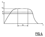
熱処理には、図4に示すように、温度を保持温度Tmまで上げ、次いでこの温度で保持時間tm保持し、大気温度まで冷却することが含まれる。 As shown in FIG. 4, the heat treatment includes raising the temperature to the holding temperature T m , holding the holding time t m at this temperature, and cooling to the atmospheric temperature.
保持時間tm及び保持温度Tmは、処理すべきブロック及び得ることが望まれる特性勾配の大きさに応じて適合される。 The holding time t m and holding temperature T m are adapted according to the block to be processed and the magnitude of the characteristic gradient that it is desired to obtain.
熱処理は、抵抗炉、又は誘導炉、又は高周波オーブンで保護雰囲気下又は真空中で実施することができる。保護雰囲気は、例えば、アルゴン、又はアルゴンと水素との混合物であるが、原則としてアルゴン、窒素、水素化アルゴン、水素化窒素、水素などの任意の中性雰囲気、又は場合によっては低真空若しくは高真空である。 The heat treatment can be performed in a resistance furnace, an induction furnace, or a high-frequency oven in a protective atmosphere or in a vacuum. The protective atmosphere is, for example, argon or a mixture of argon and hydrogen, but in principle any neutral atmosphere such as argon, nitrogen, argon hydride, nitrogen hydride, hydrogen, or in some cases low vacuum or high It is a vacuum.
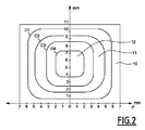
図2に示すとおり、そのように処理したブロックは、組成、特にバインダー相中の含有率が、外部から内部に異なる。この図では、バインダー相中の等濃度曲線Ciが示されており、最も外側の領域10がバインダー相中で最も少なく、その結果最も硬く、中間領域11は中間の濃度であり、バインダー相中の最も多量な領域12は最も硬くなく、その結果最も堅い。この図2に示すとおり、バインダー相中の含有率の変形形態が数ミリメートルにわたって実施されていることがわかる。したがって、超硬合金の1つの構成成分を被着させた外側の層の1つ又は複数の構成元素の作用によって、内側の領域を強化するために外側の領域を減少させることによる外側の領域から内側の領域へのバインダー相液の移行(又は移動)現象を誘導できると思われる。
As shown in FIG. 2, the block thus treated has a different composition, particularly the content in the binder phase, from the outside to the inside. In this figure, an isoconcentration curve C i in the binder phase is shown, with the
もちろん、所与の超硬合金及び所与の被膜材料では、バインダー相の含有率の変形形態によって影響を受けた領域の範囲は、保持時間tmの最高保持温度Tm、並びに被膜材料の厚さに依存する。被膜の層と同じ厚さのためには、温度Tmがより高く、時間tmがより長いほど、影響を受ける領域がより広がる、すなわち、ブロックが深さ方向により影響を受ける。 Of course, for a given cemented carbide and a given coating material, variations range of the region affected by the content of the binder phase thicknesses up to the holding temperature T m, and the coating material of the retention time t m Depends on the size. For the same thickness as the layer of the coating, the higher the temperature T m and the longer the time t m , the more the affected area is spread, i.e. the block is affected in the depth direction.
当業者は、処理条件を所望の結果にどのように適合させるかを知っている。上記のようなブロックは、その表面すべてが活性材料で覆われていることにも注意されたい。しかし、活性材料は、ブロックの外部表面の一部分にしか被着させられず、したがって被膜下に位置するブロックの領域だけで硬化又は軟化がもたらされ、したがってコーティングされていないブロックの外部表面に広げられる中心部が硬化又は軟化した領域をそれぞれ有する。 Those skilled in the art know how to adapt the processing conditions to the desired results. Note also that the block as described above is entirely covered with active material. However, the active material is only applied to a part of the outer surface of the block, so that only the area of the block located under the coating results in hardening or softening and therefore spreads on the outer surface of the uncoated block. Each of the center portions to be cured has a hardened or softened region.
ミリメートルの距離にわたってブロック内のバインダー相を分布させるこの変形形態は、外部からのバインダー相を加えることなく、実施されることに注意されたい。しかし、バインダー相が被膜の1つ又は複数の元素と結合して固相を形成することもあり、したがってブロックのバインダー相中の含有率を減少させるので、処理したブロックの全バインダー相中の含有率が同一のままであるわけではない。 Note that this variant of distributing the binder phase within the block over a distance of millimeters is carried out without the addition of an external binder phase. However, the binder phase may combine with one or more elements of the coating to form a solid phase, thus reducing the content of the block in the binder phase, so the content of the treated block in the total binder phase. The rate does not remain the same.
数百ビッカースに達し得る硬度の変形形態は、0.5mm超の距離にわたって実施することができ、ブロック全体にわたって広げることができる。 Variations in hardness that can reach hundreds of Vickers can be performed over distances greater than 0.5 mm and can be spread across the entire block.
一例として、真空中及び水素化アルゴン下で2種類の異なるコーティング(窒化ホウ素、アルミナ)を用いる同じ熱サイクル(Tm=1350℃、tm=5分)によって、同じ材料、利用可能な13重量%のコバルトを含有するWC−Co(HV2kg/10S=1220)で構成されたブロックの3つの処理を実施する。 As an example, the same material, 13 weight available, with the same thermal cycle (T m = 1350 ° C., t m = 5 min) using two different coatings (boron nitride, alumina) in vacuum and under argon hydride Three treatments of a block composed of WC-Co (HV 2 kg / 10S = 1220) containing% cobalt are carried out.
図5で10の印を付けた第1のブロックは、窒化ホウ素BNの層11を噴霧によってコーティングして、ブロックの上面及び側面を覆い、次いで真空中で処理した。
The first block marked 10 in FIG. 5 was coated with a
図6に概略図で示したように、得られたバインダー相中の濃度勾配は、領域12のようなドームの形態を有している。コーティングした表面の下に位置する領域12は、ブロックの中心部に位置する領域13よりも約130HV大きい硬度を有している。バインダー相の移動の方向は、矢印によって、及び等濃度の増大する方向(C1<C2<C3<C4)によって示されている。
As shown schematically in FIG. 6, the resulting concentration gradient in the binder phase has the shape of a dome such as
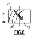
図7で20の印を付けた第2のブロックも、窒化ホウ素BNの層21でコーティングされているが、後者は、ブロックの2分の1にだけ被着させた。さらに水素化アルゴンの雰囲気下で、ブロックを処理した。
The second block, marked 20 in FIG. 7, is also coated with a
図8に示すとおり、得られたバインダー相の濃度勾配は、120HVの硬度の大きさをもたらし、被膜の下に位置する領域22だけが硬化し、残り23は硬化していない。この場合もやはり、バインダー相の移行の方向は、矢印によって、及び等濃度の増大する方向(C1<C2<C3)によって示されている。
As shown in FIG. 8, the resulting binder phase concentration gradient results in a 120 HV hardness scale, with only the
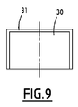
図9で30の印を付けた第3のブロックは、ブラシを用いてブロックの上面及び側面上に液体ペーストの形態で被着させて真空中で処理した酸化アルミニウムAl2O3の層31でコーティングされた。図10に示すとおり、バインダー相中の濃度勾配は、ドームの形で得られたが、第1のブロックで得られたものとは反対に、表面に近い領域32は、それらの硬度が中心部の領域33の硬度よりも150HV小さいように軟化された。バインダー相の移動の方向は、矢印によって、及び等濃度の増大する方向(C1<C2<C3<C4)によって示されており、その方向は、上記の2例に関して逆である。
The third block marked 30 in FIG. 9 is a
そのように、考慮中のWC−Co材料の場合は、窒化ホウ素が被膜の層に近いブロックの領域の軟化を可能にし、一方アルミナが硬化を可能にする。 As such, in the case of the WC-Co material under consideration, boron nitride allows softening of the area of the block close to the layer of the coating, while alumina allows hardening.
他方では、処理を実施するために使用した炉の雰囲気(真空又は水素化アルゴン)は、結果に影響を与えない。 On the other hand, the furnace atmosphere (vacuum or argon hydride) used to carry out the treatment does not affect the results.
先に示したように、そのように処理したブロックは、穴あけ工具又は切削工具の刃先を構成でき、数ミリメートル又はさらに大きい寸法であってよい。それは、寸法が数センチメートルで、且つこの方法によって硬化できる切刃(cutting blades)を達成すると考えることができるからである。 As indicated above, such a treated block can constitute the cutting edge of a drilling or cutting tool and may be several millimeters or larger in size. This is because it can be considered to achieve cutting blades that are several centimeters in size and can be cured by this method.
図3に示すように、岩石を削るための工具用又は耐火材料若しくは機械加工のための切削工具用の刃先も達成され、該刃先は本発明に基づく方法を用いて達成した超硬合金中のブロック支持体20で構成されており、その外側面は硬く、且つ中心部がより堅く(C1<C2<C3<C4)、且つその内側面を熱処理前にコーティングしておらず、且つその処理後の上面に、PDC(多結晶ダイヤモンド成形体)型又はTSP(熱安定多結晶ダイヤモンド)型のHPHT(高圧−高温)法によって厚さが0.4mm超の天然又は合成ダイヤモンドで被覆されたプレート21を加えている。
As shown in FIG. 3, a cutting edge for a tool for cutting rocks or for a cutting tool for refractory materials or machining is also achieved, said cutting edge in a cemented carbide achieved using the method according to the invention. It consists of a
特に、本発明に従って処理したブロック支持体20は、例えば、「LS Bond」として知られ、且つ米国特許第4225322号明細書及び米国特許第5111895号明細書に記載されている方法に従って、ろう付によってHPHT法の後に構築できたものであるが、この操作を行わなくともバインダー相中の濃度の勾配のブロックの劇的な変更形態をもたらす。
In particular, the
この方法によって、当業者が想像できる以外の刃先を達成することができる。これらの刃先は、岩石破砕用、穴あけヘッド用又は機械加工工具用の工具など、当業者に既知の多様な工具に組み込むことができる。
By this method, cutting edges other than those imaginable by those skilled in the art can be achieved. These cutting edges can be incorporated into a variety of tools known to those skilled in the art, such as tools for rock crushing, drilling heads or machining tools.
Claims (17)
A tool for cutting rock, comprising at least one cutting edge or blade according to claim 15 or claim 16.
Applications Claiming Priority (3)
| Application Number | Priority Date | Filing Date | Title |
|---|---|---|---|
| FR0856771 | 2008-10-07 | ||
| FR0856771A FR2936817B1 (en) | 2008-10-07 | 2008-10-07 | PROCESS FOR MANUFACTURING A WORKPIECE COMPRISING A BLOCK OF DENSE MATERIAL OF THE CEMENT CARBIDE TYPE, HAVING A LARGE NUMBER OF PROPERTIES AND PIECE OBTAINED |
| PCT/FR2009/051910 WO2010040953A1 (en) | 2008-10-07 | 2009-10-07 | Process for manufacturing a part comprising a block of dense material constituted of hard particles and of binder phase having a gradient of properties, and resulting part. |
Publications (2)
| Publication Number | Publication Date |
|---|---|
| JP2012505306A true JP2012505306A (en) | 2012-03-01 |
| JP5622731B2 JP5622731B2 (en) | 2014-11-12 |
Family
ID=40750782
Family Applications (1)
| Application Number | Title | Priority Date | Filing Date |
|---|---|---|---|
| JP2011529611A Active JP5622731B2 (en) | 2008-10-07 | 2009-10-07 | Method for producing a part comprising a block of cemented carbide type high density material having a characteristic gradient and the resulting part |
Country Status (6)
| Country | Link |
|---|---|
| US (1) | US8602131B2 (en) |
| EP (1) | EP2347025B1 (en) |
| JP (1) | JP5622731B2 (en) |
| CN (1) | CN102282278A (en) |
| FR (1) | FR2936817B1 (en) |
| WO (1) | WO2010040953A1 (en) |
Families Citing this family (15)
| Publication number | Priority date | Publication date | Assignee | Title |
|---|---|---|---|---|
| US9428822B2 (en) | 2004-04-28 | 2016-08-30 | Baker Hughes Incorporated | Earth-boring tools and components thereof including material having hard phase in a metallic binder, and metallic binder compositions for use in forming such tools and components |
| FR2914206B1 (en) * | 2007-03-27 | 2009-09-04 | Sas Varel Europ Soc Par Action | PROCESS FOR MANUFACTURING A WORKPIECE COMPRISING AT LEAST ONE BLOCK OF DENSE MATERIAL CONSISTING OF HARD PARTICLES DISPERSE IN A BINDER PHASE: APPLICATION TO CUTTING OR DRILLING TOOLS. |
| US8858871B2 (en) | 2007-03-27 | 2014-10-14 | Varel International Ind., L.P. | Process for the production of a thermally stable polycrystalline diamond compact |
| FR2936817B1 (en) * | 2008-10-07 | 2013-07-19 | Varel Europ | PROCESS FOR MANUFACTURING A WORKPIECE COMPRISING A BLOCK OF DENSE MATERIAL OF THE CEMENT CARBIDE TYPE, HAVING A LARGE NUMBER OF PROPERTIES AND PIECE OBTAINED |
| US8978734B2 (en) | 2010-05-20 | 2015-03-17 | Baker Hughes Incorporated | Methods of forming at least a portion of earth-boring tools, and articles formed by such methods |
| CN102985197A (en) | 2010-05-20 | 2013-03-20 | 贝克休斯公司 | Methods of forming at least a portion of earth-boring tools, and articles formed by such methods |
| US8522900B2 (en) | 2010-09-17 | 2013-09-03 | Varel Europe S.A.S. | High toughness thermally stable polycrystalline diamond |
| JP6809918B2 (en) * | 2017-01-31 | 2021-01-06 | 三菱重工業株式会社 | Heat treatment method and manufacturing method for metal molded products |
| TWI652352B (en) * | 2017-09-21 | 2019-03-01 | 國立清華大學 | Eutectic porcelain gold material |
| JP6762331B2 (en) * | 2018-03-09 | 2020-09-30 | 三菱重工業株式会社 | Manufacturing method of metal molded products |
| US11052496B2 (en) * | 2019-09-26 | 2021-07-06 | Worldwide Machinery, Ltd. | Backing material for welding |
| EP4240882A1 (en) | 2020-11-05 | 2023-09-13 | Diamond Innovations, Inc. | Cemented tungsten carbide body and method of forming the cemented tungsten carbide body |
| EP4275856A1 (en) * | 2022-05-10 | 2023-11-15 | Hilti Aktiengesellschaft | Durable chisel and method for manufacturing such a chisel |
| CN115786791B (en) * | 2022-12-22 | 2024-02-13 | 杨冠华 | Mechanical crushing hammer and preparation process thereof |
| CN116408435B (en) * | 2023-04-12 | 2023-11-03 | 哈尔滨工业大学 | Method for preparing diamond/metal composite material in high flux |
Citations (4)
| Publication number | Priority date | Publication date | Assignee | Title |
|---|---|---|---|---|
| JPH05171335A (en) * | 1991-12-16 | 1993-07-09 | Toshiba Tungaloy Co Ltd | Differential layer surface refined sintered alloy and its manufacture |
| JP2004060201A (en) * | 2002-07-26 | 2004-02-26 | Mitsubishi Materials Corp | Cutting edge piece of excavating tool for exhibiting superior fine chipping resistance under high speed rotary operation condition |
| JP2006188749A (en) * | 2004-12-09 | 2006-07-20 | Sanalloy Industry Co Ltd | High-strength hard metal, production method therefor, and tool using it |
| EP1975264A1 (en) * | 2007-03-27 | 2008-10-01 | Varel Europe | Method of manufacturing a part comprising at least one block made from a dense material consisting of hard particles dispersed in a binding phase: application to cutting or drilling tools. |
Family Cites Families (48)
| Publication number | Priority date | Publication date | Assignee | Title |
|---|---|---|---|---|
| US3745623A (en) * | 1971-12-27 | 1973-07-17 | Gen Electric | Diamond tools for machining |
| US4225322A (en) * | 1978-01-10 | 1980-09-30 | General Electric Company | Composite compact components fabricated with high temperature brazing filler metal and method for making same |
| US4402764A (en) * | 1981-03-05 | 1983-09-06 | Turbine Metal Technology, Inc. | Method for producing abrasion and erosion resistant articles |
| US4610931A (en) * | 1981-03-27 | 1986-09-09 | Kennametal Inc. | Preferentially binder enriched cemented carbide bodies and method of manufacture |
| DE3112460C2 (en) * | 1981-03-28 | 1983-01-20 | Fried. Krupp Gmbh, 4300 Essen | Process for the production of a composite body and application of this process |
| DD203750A1 (en) * | 1982-02-10 | 1983-11-02 | Immelborn Hartmetallwerk | HARDMETAL CUTTING PLATE FOR HEAVY-DUTY STAIRS |
| US4548786A (en) * | 1983-04-28 | 1985-10-22 | General Electric Company | Coated carbide cutting tool insert |
| US5028177A (en) * | 1984-03-26 | 1991-07-02 | Eastman Christensen Company | Multi-component cutting element using triangular, rectangular and higher order polyhedral-shaped polycrystalline diamond disks |
| US4726718A (en) | 1984-03-26 | 1988-02-23 | Eastman Christensen Co. | Multi-component cutting element using triangular, rectangular and higher order polyhedral-shaped polycrystalline diamond disks |
| US4525178A (en) * | 1984-04-16 | 1985-06-25 | Megadiamond Industries, Inc. | Composite polycrystalline diamond |
| EP0182759B2 (en) * | 1984-11-13 | 1993-12-15 | Santrade Ltd. | Cemented carbide body used preferably for rock drilling and mineral cutting |
| JPS6274076A (en) * | 1985-09-27 | 1987-04-04 | Sumitomo Electric Ind Ltd | Production of multi-layer coated hard alloy |
| SE456428B (en) * | 1986-05-12 | 1988-10-03 | Santrade Ltd | HARD METAL BODY FOR MOUNTAIN DRILLING WITH BINDING PHASE GRADIENT AND WANTED TO MAKE IT SAME |
| US4943488A (en) * | 1986-10-20 | 1990-07-24 | Norton Company | Low pressure bonding of PCD bodies and method for drill bits and the like |
| US5111895A (en) * | 1988-03-11 | 1992-05-12 | Griffin Nigel D | Cutting elements for rotary drill bits |
| US5011514A (en) * | 1988-07-29 | 1991-04-30 | Norton Company | Cemented and cemented/sintered superabrasive polycrystalline bodies and methods of manufacture thereof |
| US6413589B1 (en) * | 1988-11-29 | 2002-07-02 | Chou H. Li | Ceramic coating method |
| JPH0349834A (en) * | 1989-07-14 | 1991-03-04 | Sumitomo Electric Ind Ltd | Tool using gold as sealant and manufacture thereof |
| JP3191878B2 (en) * | 1991-02-21 | 2001-07-23 | 三菱マテリアル株式会社 | Manufacturing method of vapor-phase synthetic diamond coated cutting tool |
| AU2794592A (en) * | 1991-10-28 | 1993-06-07 | Alcan International Limited | Method for modifying the surface of an aluminum substrate |
| US5441817A (en) * | 1992-10-21 | 1995-08-15 | Smith International, Inc. | Diamond and CBN cutting tools |
| US5839329A (en) * | 1994-03-16 | 1998-11-24 | Baker Hughes Incorporated | Method for infiltrating preformed components and component assemblies |
| US5560839A (en) * | 1994-06-27 | 1996-10-01 | Valenite Inc. | Methods of preparing cemented metal carbide substrates for deposition of adherent diamond coatings and products made therefrom |
| US7396501B2 (en) * | 1994-08-12 | 2008-07-08 | Diamicron, Inc. | Use of gradient layers and stress modifiers to fabricate composite constructs |
| US5726718A (en) * | 1994-09-30 | 1998-03-10 | Texas Instruments Incorporated | Error diffusion filter for DMD display |
| JP3309897B2 (en) * | 1995-11-15 | 2002-07-29 | 住友電気工業株式会社 | Ultra-hard composite member and method of manufacturing the same |
| US5880382A (en) * | 1996-08-01 | 1999-03-09 | Smith International, Inc. | Double cemented carbide composites |
| AU5960698A (en) * | 1997-01-17 | 1998-08-07 | California Institute Of Technology | Microwave technique for brazing materials |
| US6679243B2 (en) * | 1997-04-04 | 2004-01-20 | Chien-Min Sung | Brazed diamond tools and methods for making |
| AU3389699A (en) * | 1998-04-22 | 1999-11-08 | De Beers Industrial Diamond Division (Proprietary) Limited | Diamond compact |
| US6592985B2 (en) * | 2000-09-20 | 2003-07-15 | Camco International (Uk) Limited | Polycrystalline diamond partially depleted of catalyzing material |
| KR101021461B1 (en) * | 2002-07-26 | 2011-03-16 | 미쓰비시 마테리알 가부시키가이샤 | Bonding structure and bonding method for cemented carbide and diamond element, cutting tip and cutting element for drilling tool, and drilling tool |
| US7261752B2 (en) * | 2002-09-24 | 2007-08-28 | Chien-Min Sung | Molten braze-coated superabrasive particles and associated methods |
| US6869460B1 (en) * | 2003-09-22 | 2005-03-22 | Valenite, Llc | Cemented carbide article having binder gradient and process for producing the same |
| US7699904B2 (en) * | 2004-06-14 | 2010-04-20 | University Of Utah Research Foundation | Functionally graded cemented tungsten carbide |
| CA2535387C (en) * | 2005-02-08 | 2013-05-07 | Smith International, Inc. | Thermally stable polycrystalline diamond cutting elements and bits incorporating the same |
| US7487849B2 (en) * | 2005-05-16 | 2009-02-10 | Radtke Robert P | Thermally stable diamond brazing |
| US7377341B2 (en) * | 2005-05-26 | 2008-05-27 | Smith International, Inc. | Thermally stable ultra-hard material compact construction |
| US7887747B2 (en) * | 2005-09-12 | 2011-02-15 | Sanalloy Industry Co., Ltd. | High strength hard alloy and method of preparing the same |
| US7757793B2 (en) * | 2005-11-01 | 2010-07-20 | Smith International, Inc. | Thermally stable polycrystalline ultra-hard constructions |
| US8066087B2 (en) | 2006-05-09 | 2011-11-29 | Smith International, Inc. | Thermally stable ultra-hard material compact constructions |
| US8002859B2 (en) * | 2007-02-06 | 2011-08-23 | Smith International, Inc. | Manufacture of thermally stable cutting elements |
| US7942219B2 (en) * | 2007-03-21 | 2011-05-17 | Smith International, Inc. | Polycrystalline diamond constructions having improved thermal stability |
| US8061454B2 (en) * | 2008-01-09 | 2011-11-22 | Smith International, Inc. | Ultra-hard and metallic constructions comprising improved braze joint |
| WO2009111749A1 (en) | 2008-03-07 | 2009-09-11 | University Of Utah | Thermal degradation and crack resistant functionally graded cemented tungsten carbide and polycrystalline diamond |
| FR2936817B1 (en) * | 2008-10-07 | 2013-07-19 | Varel Europ | PROCESS FOR MANUFACTURING A WORKPIECE COMPRISING A BLOCK OF DENSE MATERIAL OF THE CEMENT CARBIDE TYPE, HAVING A LARGE NUMBER OF PROPERTIES AND PIECE OBTAINED |
| EP2184122A1 (en) * | 2008-11-11 | 2010-05-12 | Sandvik Intellectual Property AB | Cemented carbide body and method |
| WO2011017582A2 (en) * | 2009-08-07 | 2011-02-10 | Smith International, Inc. | Functionally graded polycrystalline diamond insert |
-
2008
- 2008-10-07 FR FR0856771A patent/FR2936817B1/en active Active
-
2009
- 2009-10-07 WO PCT/FR2009/051910 patent/WO2010040953A1/en active Application Filing
- 2009-10-07 EP EP09755981A patent/EP2347025B1/en active Active
- 2009-10-07 US US13/121,366 patent/US8602131B2/en active Active
- 2009-10-07 CN CN2009801392426A patent/CN102282278A/en active Pending
- 2009-10-07 JP JP2011529611A patent/JP5622731B2/en active Active
Patent Citations (6)
| Publication number | Priority date | Publication date | Assignee | Title |
|---|---|---|---|---|
| JPH05171335A (en) * | 1991-12-16 | 1993-07-09 | Toshiba Tungaloy Co Ltd | Differential layer surface refined sintered alloy and its manufacture |
| JP2004060201A (en) * | 2002-07-26 | 2004-02-26 | Mitsubishi Materials Corp | Cutting edge piece of excavating tool for exhibiting superior fine chipping resistance under high speed rotary operation condition |
| JP2006188749A (en) * | 2004-12-09 | 2006-07-20 | Sanalloy Industry Co Ltd | High-strength hard metal, production method therefor, and tool using it |
| EP1975264A1 (en) * | 2007-03-27 | 2008-10-01 | Varel Europe | Method of manufacturing a part comprising at least one block made from a dense material consisting of hard particles dispersed in a binding phase: application to cutting or drilling tools. |
| US20080240879A1 (en) * | 2007-03-27 | 2008-10-02 | Varel International, Ind., L.P. | Process for the production of an element comprising at least one block of dense material constituted by hard particles dispersed in a binder phase: application to cutting or drilling tools |
| JP2009030157A (en) * | 2007-03-27 | 2009-02-12 | Varel Europe | Process for the production of element comprising at least one block of dense material constituted by hard particle dispersed in binder phase, and application to cutting or drilling tool |
Also Published As
| Publication number | Publication date |
|---|---|
| US20110174550A1 (en) | 2011-07-21 |
| EP2347025A1 (en) | 2011-07-27 |
| FR2936817B1 (en) | 2013-07-19 |
| FR2936817A1 (en) | 2010-04-09 |
| US8602131B2 (en) | 2013-12-10 |
| CN102282278A (en) | 2011-12-14 |
| WO2010040953A1 (en) | 2010-04-15 |
| EP2347025B1 (en) | 2013-01-16 |
| JP5622731B2 (en) | 2014-11-12 |
Similar Documents
| Publication | Publication Date | Title |
|---|---|---|
| JP5622731B2 (en) | Method for producing a part comprising a block of cemented carbide type high density material having a characteristic gradient and the resulting part | |
| US8647562B2 (en) | Process for the production of an element comprising at least one block of dense material constituted by hard particles dispersed in a binder phase: application to cutting or drilling tools | |
| US4548786A (en) | Coated carbide cutting tool insert | |
| US8858871B2 (en) | Process for the production of a thermally stable polycrystalline diamond compact | |
| CA2603458C (en) | Atomic layer deposition nanocoatings on cutting tool powder materials | |
| US8968834B2 (en) | Wear part with hard facing | |
| US4497874A (en) | Coated carbide cutting tool insert | |
| RU2521937C2 (en) | Hard alloy body | |
| US20020095875A1 (en) | Abrasive diamond composite and method of making thereof | |
| US9346148B2 (en) | Superabrasive material with protective adhesive coating and method for producing said coating | |
| US20120040157A1 (en) | Superhard element, a tool comprising same and methods for making such superhard element | |
| JP4653922B2 (en) | Method of attaching a coating to a substrate composed of diamond or a diamond-containing material | |
| EP2715784B1 (en) | Manufacturing process for a thick cubic boron nitride (cbn) layer | |
| RU2510823C2 (en) | Heat-resistant polycrystalline diamond composite | |
| JPS6026624A (en) | Manufacture of sintered diamond body | |
| JP2000144298A (en) | Diamond-containing hard member and its production | |
| JP2011051890A (en) | Adhesive composite coating film for diamond and for diamond-containing material, and method for producing the same | |
| JP2819648B2 (en) | Coated cemented carbide for wear-resistant tools | |
| JPS63111105A (en) | Composite sintered body and its production |
Legal Events
| Date | Code | Title | Description |
|---|---|---|---|
| A621 | Written request for application examination |
Free format text: JAPANESE INTERMEDIATE CODE: A621 Effective date: 20120910 |
|
| A521 | Request for written amendment filed |
Free format text: JAPANESE INTERMEDIATE CODE: A523 Effective date: 20140218 |
|
| A02 | Decision of refusal |
Free format text: JAPANESE INTERMEDIATE CODE: A02 Effective date: 20140311 |
|
| A521 | Request for written amendment filed |
Free format text: JAPANESE INTERMEDIATE CODE: A523 Effective date: 20140709 |
|
| A521 | Request for written amendment filed |
Free format text: JAPANESE INTERMEDIATE CODE: A821 Effective date: 20140709 |
|
| A521 | Request for written amendment filed |
Free format text: JAPANESE INTERMEDIATE CODE: A523 Effective date: 20140730 |
|
| A911 | Transfer to examiner for re-examination before appeal (zenchi) |
Free format text: JAPANESE INTERMEDIATE CODE: A911 Effective date: 20140806 |
|
| TRDD | Decision of grant or rejection written | ||
| A01 | Written decision to grant a patent or to grant a registration (utility model) |
Free format text: JAPANESE INTERMEDIATE CODE: A01 Effective date: 20140826 |
|
| A61 | First payment of annual fees (during grant procedure) |
Free format text: JAPANESE INTERMEDIATE CODE: A61 Effective date: 20140922 |
|
| R150 | Certificate of patent or registration of utility model |
Ref document number: 5622731 Country of ref document: JP Free format text: JAPANESE INTERMEDIATE CODE: R150 |
|
| S531 | Written request for registration of change of domicile |
Free format text: JAPANESE INTERMEDIATE CODE: R313531 |
|
| R350 | Written notification of registration of transfer |
Free format text: JAPANESE INTERMEDIATE CODE: R350 |
|
| RD02 | Notification of acceptance of power of attorney |
Free format text: JAPANESE INTERMEDIATE CODE: R3D02 |
|
| R250 | Receipt of annual fees |
Free format text: JAPANESE INTERMEDIATE CODE: R250 |
|
| R250 | Receipt of annual fees |
Free format text: JAPANESE INTERMEDIATE CODE: R250 |
|
| R250 | Receipt of annual fees |
Free format text: JAPANESE INTERMEDIATE CODE: R250 |
|
| S111 | Request for change of ownership or part of ownership |
Free format text: JAPANESE INTERMEDIATE CODE: R313113 |
|
| R350 | Written notification of registration of transfer |
Free format text: JAPANESE INTERMEDIATE CODE: R350 |
|
| RD02 | Notification of acceptance of power of attorney |
Free format text: JAPANESE INTERMEDIATE CODE: R3D02 |
|
| R250 | Receipt of annual fees |
Free format text: JAPANESE INTERMEDIATE CODE: R250 |
|
| R250 | Receipt of annual fees |
Free format text: JAPANESE INTERMEDIATE CODE: R250 |
|
| R250 | Receipt of annual fees |
Free format text: JAPANESE INTERMEDIATE CODE: R250 |
|
| R250 | Receipt of annual fees |
Free format text: JAPANESE INTERMEDIATE CODE: R250 |