JP2012503531A - Inhaler with individual airway passage and associated disc and method - Google Patents
Inhaler with individual airway passage and associated disc and method Download PDFInfo
- Publication number
- JP2012503531A JP2012503531A JP2011529238A JP2011529238A JP2012503531A JP 2012503531 A JP2012503531 A JP 2012503531A JP 2011529238 A JP2011529238 A JP 2011529238A JP 2011529238 A JP2011529238 A JP 2011529238A JP 2012503531 A JP2012503531 A JP 2012503531A
- Authority
- JP
- Japan
- Prior art keywords
- airway
- dose container
- disk
- dry powder
- dose
- Prior art date
- Legal status (The legal status is an assumption and is not a legal conclusion. Google has not performed a legal analysis and makes no representation as to the accuracy of the status listed.)
- Granted
Links
Images


Classifications
-
- A—HUMAN NECESSITIES
- A61—MEDICAL OR VETERINARY SCIENCE; HYGIENE
- A61M—DEVICES FOR INTRODUCING MEDIA INTO, OR ONTO, THE BODY; DEVICES FOR TRANSDUCING BODY MEDIA OR FOR TAKING MEDIA FROM THE BODY; DEVICES FOR PRODUCING OR ENDING SLEEP OR STUPOR
- A61M15/00—Inhalators
-
- A—HUMAN NECESSITIES
- A61—MEDICAL OR VETERINARY SCIENCE; HYGIENE
- A61M—DEVICES FOR INTRODUCING MEDIA INTO, OR ONTO, THE BODY; DEVICES FOR TRANSDUCING BODY MEDIA OR FOR TAKING MEDIA FROM THE BODY; DEVICES FOR PRODUCING OR ENDING SLEEP OR STUPOR
- A61M15/00—Inhalators
- A61M15/0028—Inhalators using prepacked dosages, one for each application, e.g. capsules to be perforated or broken-up
- A61M15/0045—Inhalators using prepacked dosages, one for each application, e.g. capsules to be perforated or broken-up using multiple prepacked dosages on a same carrier, e.g. blisters
- A61M15/0046—Inhalators using prepacked dosages, one for each application, e.g. capsules to be perforated or broken-up using multiple prepacked dosages on a same carrier, e.g. blisters characterized by the type of carrier
- A61M15/0048—Inhalators using prepacked dosages, one for each application, e.g. capsules to be perforated or broken-up using multiple prepacked dosages on a same carrier, e.g. blisters characterized by the type of carrier the dosages being arranged in a plane, e.g. on diskettes
-
- A—HUMAN NECESSITIES
- A61—MEDICAL OR VETERINARY SCIENCE; HYGIENE
- A61J—CONTAINERS SPECIALLY ADAPTED FOR MEDICAL OR PHARMACEUTICAL PURPOSES; DEVICES OR METHODS SPECIALLY ADAPTED FOR BRINGING PHARMACEUTICAL PRODUCTS INTO PARTICULAR PHYSICAL OR ADMINISTERING FORMS; DEVICES FOR ADMINISTERING FOOD OR MEDICINES ORALLY; BABY COMFORTERS; DEVICES FOR RECEIVING SPITTLE
- A61J1/00—Containers specially adapted for medical or pharmaceutical purposes
- A61J1/05—Containers specially adapted for medical or pharmaceutical purposes for collecting, storing or administering blood, plasma or medical fluids ; Infusion or perfusion containers
-
- A—HUMAN NECESSITIES
- A61—MEDICAL OR VETERINARY SCIENCE; HYGIENE
- A61M—DEVICES FOR INTRODUCING MEDIA INTO, OR ONTO, THE BODY; DEVICES FOR TRANSDUCING BODY MEDIA OR FOR TAKING MEDIA FROM THE BODY; DEVICES FOR PRODUCING OR ENDING SLEEP OR STUPOR
- A61M15/00—Inhalators
- A61M15/0001—Details of inhalators; Constructional features thereof
- A61M15/0021—Mouthpieces therefor
-
- A—HUMAN NECESSITIES
- A61—MEDICAL OR VETERINARY SCIENCE; HYGIENE
- A61M—DEVICES FOR INTRODUCING MEDIA INTO, OR ONTO, THE BODY; DEVICES FOR TRANSDUCING BODY MEDIA OR FOR TAKING MEDIA FROM THE BODY; DEVICES FOR PRODUCING OR ENDING SLEEP OR STUPOR
- A61M15/00—Inhalators
- A61M15/0028—Inhalators using prepacked dosages, one for each application, e.g. capsules to be perforated or broken-up
- A61M15/003—Inhalators using prepacked dosages, one for each application, e.g. capsules to be perforated or broken-up using capsules, e.g. to be perforated or broken-up
- A61M15/0033—Details of the piercing or cutting means
- A61M15/0035—Piercing means
-
- A—HUMAN NECESSITIES
- A61—MEDICAL OR VETERINARY SCIENCE; HYGIENE
- A61M—DEVICES FOR INTRODUCING MEDIA INTO, OR ONTO, THE BODY; DEVICES FOR TRANSDUCING BODY MEDIA OR FOR TAKING MEDIA FROM THE BODY; DEVICES FOR PRODUCING OR ENDING SLEEP OR STUPOR
- A61M15/00—Inhalators
- A61M15/0028—Inhalators using prepacked dosages, one for each application, e.g. capsules to be perforated or broken-up
- A61M15/003—Inhalators using prepacked dosages, one for each application, e.g. capsules to be perforated or broken-up using capsules, e.g. to be perforated or broken-up
- A61M15/0033—Details of the piercing or cutting means
- A61M15/0041—Details of the piercing or cutting means with movable piercing or cutting means
-
- A—HUMAN NECESSITIES
- A61—MEDICAL OR VETERINARY SCIENCE; HYGIENE
- A61M—DEVICES FOR INTRODUCING MEDIA INTO, OR ONTO, THE BODY; DEVICES FOR TRANSDUCING BODY MEDIA OR FOR TAKING MEDIA FROM THE BODY; DEVICES FOR PRODUCING OR ENDING SLEEP OR STUPOR
- A61M15/00—Inhalators
- A61M15/0028—Inhalators using prepacked dosages, one for each application, e.g. capsules to be perforated or broken-up
- A61M15/0045—Inhalators using prepacked dosages, one for each application, e.g. capsules to be perforated or broken-up using multiple prepacked dosages on a same carrier, e.g. blisters
-
- A—HUMAN NECESSITIES
- A61—MEDICAL OR VETERINARY SCIENCE; HYGIENE
- A61M—DEVICES FOR INTRODUCING MEDIA INTO, OR ONTO, THE BODY; DEVICES FOR TRANSDUCING BODY MEDIA OR FOR TAKING MEDIA FROM THE BODY; DEVICES FOR PRODUCING OR ENDING SLEEP OR STUPOR
- A61M15/00—Inhalators
- A61M15/0065—Inhalators with dosage or measuring devices
- A61M15/0068—Indicating or counting the number of dispensed doses or of remaining doses
- A61M15/007—Mechanical counters
- A61M15/0071—Mechanical counters having a display or indicator
- A61M15/0075—Mechanical counters having a display or indicator on a disc
-
- A—HUMAN NECESSITIES
- A61—MEDICAL OR VETERINARY SCIENCE; HYGIENE
- A61M—DEVICES FOR INTRODUCING MEDIA INTO, OR ONTO, THE BODY; DEVICES FOR TRANSDUCING BODY MEDIA OR FOR TAKING MEDIA FROM THE BODY; DEVICES FOR PRODUCING OR ENDING SLEEP OR STUPOR
- A61M2202/00—Special media to be introduced, removed or treated
- A61M2202/06—Solids
- A61M2202/064—Powder
-
- Y—GENERAL TAGGING OF NEW TECHNOLOGICAL DEVELOPMENTS; GENERAL TAGGING OF CROSS-SECTIONAL TECHNOLOGIES SPANNING OVER SEVERAL SECTIONS OF THE IPC; TECHNICAL SUBJECTS COVERED BY FORMER USPC CROSS-REFERENCE ART COLLECTIONS [XRACs] AND DIGESTS
- Y10—TECHNICAL SUBJECTS COVERED BY FORMER USPC
- Y10T—TECHNICAL SUBJECTS COVERED BY FORMER US CLASSIFICATION
- Y10T29/00—Metal working
- Y10T29/49—Method of mechanical manufacture
- Y10T29/49826—Assembling or joining
Landscapes
- Health & Medical Sciences (AREA)
- Engineering & Computer Science (AREA)
- Life Sciences & Earth Sciences (AREA)
- Veterinary Medicine (AREA)
- General Health & Medical Sciences (AREA)
- Public Health (AREA)
- Animal Behavior & Ethology (AREA)
- Hematology (AREA)
- Pulmonology (AREA)
- Heart & Thoracic Surgery (AREA)
- Anesthesiology (AREA)
- Biomedical Technology (AREA)
- Bioinformatics & Cheminformatics (AREA)
- Biophysics (AREA)
- Pharmacology & Pharmacy (AREA)
- Medical Preparation Storing Or Oral Administration Devices (AREA)
- Medicinal Preparation (AREA)
- Acyclic And Carbocyclic Compounds In Medicinal Compositions (AREA)
- Closures For Containers (AREA)
Abstract
ドライパウダー吸入器は、半径方向に延在している離隔された、典型的には、ドーズに対して特定されている気道通路を備えている。これらの気道通路は、吸入器内のドライパウダーを送達する吸入経路の一部を順次形成するようになっている。 Dry powder inhalers include spaced apart, typically airway passages that are specific to the dose extending radially. These airway passages sequentially form part of the inhalation route for delivering the dry powder in the inhaler.
Description
[関連出願の相互参照]
本出願は、2008年9月26日に出願された米国仮出願第61/100,482号および2009年1月30日に出願された米国仮出願第61/148,520号の利得および優先権を主張するものであり、その開示内容は、参照することによって、その全体が記載されているのと同様に、ここに含まれるものとする。
[Cross-reference of related applications]
This application claims the benefit and priority of US provisional application 61 / 100,482, filed September 26, 2008 and US provisional application 61 / 148,520, filed January 30, 2009. The disclosure of which is hereby incorporated by reference as if set forth in its entirety.
[発明の分野]
本発明は、吸入器に関し、ドライパウダー吸入器に特に適するものである。
[Field of the Invention]
The present invention relates to an inhaler and is particularly suitable for a dry powder inhaler.
一般的に、周知の一回投与型/多数回投与型ドライパウダー吸入器(DPI)は、加圧式定量噴霧吸入器(pMDI)に対する、すでに認められている代替品である。DPIは、(a)投与の前に装置内に挿入可能になっている薬剤を含むブリスター内の個々の予計量されているドーズ(dose、用量)を用いるか、または(b)適切なドーズを投与するようになっている投与チャンバを介して、患者に連続的な量の薬剤を投与するように構成されたバルクパウダー容器を用いることができる。非特許文献1,2を一般的に参照されたい。
In general, the well-known single-dose / multi-dose dry powder inhaler (DPI) is an accepted replacement for the pressurized metered dose inhaler (pMDI). DPI uses (a) individual pre-metered doses in blisters containing drugs that can be inserted into the device prior to administration, or (b) use appropriate doses A bulk powder container configured to administer a continuous amount of drug to a patient through a dosing chamber adapted to dispense can be used. Refer generally to
操作に関して、DPI装置は、所望の物理的な形態(例えば、粒径)を有するドライパウダーの均一なエアロゾル分散量を患者の気道内に投与し、所望の内部滞留部位に導くことを目指している。 In operation, the DPI device aims to administer a uniform aerosol dispersion of dry powder having the desired physical form (eg, particle size) into the patient's respiratory tract, leading to the desired internal residence site. .
しかし、残念ながら、ドライパウダー吸入器の内には、いくらかの量の薬剤が装置内に残ることがあり、この残った薬剤が他の薬剤ドーズと共に送達される可能性のあるものがある。これは、特に、利用者が吸入器を作動させたにもかかわらず、割り出された薬剤ドーズを吸入しなかったときに生じる傾向がある。 Unfortunately, however, some dry powder inhalers can leave some amount of drug in the device, which can be delivered with other drug doses. This tends to occur especially when the user has activated the inhaler but has not inhaled the determined drug dose.
薬剤を送達するのに用いることができる代替的な吸入器および/またはドーズ格納装置が依然として必要とされている。 There remains a need for alternative inhalers and / or dose storage devices that can be used to deliver medication.
本発明の実施形態は、吸入ポートと真っ直ぐに並んでおり、それぞれのドーズ容器からドライパウダーを取り込み、吸入器の利用者にドライパウダーを投与するための吸入口への吸入経路の一部をなす個々の気道通路を、1つまたは複数のドーズ容器に対して画定することができるドーズ容器アセンブリを提供している。 Embodiments of the present invention are lined up directly with the inhalation ports and take in dry powder from each dose container and form part of the inhalation route to the inhalation port for administering the dry powder to the user of the inhaler. A dose container assembly is provided in which individual airway passages can be defined relative to one or more dose containers.
いくつかの実施形態は、(a)相背向する上側および下側主面および周方向に離隔された複数のドーズ容器を有するドーズ容器ディスクと、(b)ドーズ容器ディスクの上または下に位置する少なくとも1つの気道ディスクと、を備えているドライパウダードーズ容器アセンブリに向けられている。少なくとも1つの気道ディスクは、周方向に離隔された複数の気道通路を備えている。ドーズ容器は、該ドーズ容器内に密封されたドライパウダーを有することができる。 Some embodiments include: (a) a dose container disk having opposing upper and lower major surfaces and a plurality of circumferentially spaced dose containers; and (b) located above or below the dose container disk. At least one airway disk that is directed to a dry powder dose container assembly. At least one airway disk includes a plurality of airway passages spaced circumferentially. The dose container can have a dry powder sealed within the dose container.
本発明の実施形態は、ドライパウダードーズ容器アセンブリに向けられている。このアセンブリは、(a)周方向に離隔された複数のドーズ容器を有するドーズ容器ディスクであって、ドーズ容器が、該ドーズ容器内に(典型的には、所定量または測定された量の)ドライパウダーを有する、ドーズ容器ディスクと、(b)ドーズ容器ディスクの上に位置している上側気道ディスクと、(c)ドーズ容器ディスクの下に位置している下側気道ディスクと、を備えている。上側および下側気道ディスクは、各々、周方向において離隔された複数の通路を備えており、下側気道ディスク通路と上側気道ディスク通路との対は、少なくとも1つの対応するドーズ容器をそれらの間に挟んで、互いに真っ直ぐに並んで配置されている。 Embodiments of the present invention are directed to a dry powder dose container assembly. The assembly is (a) a dose container disc having a plurality of dose containers spaced circumferentially, wherein the dose container is within the dose container (typically a predetermined or measured amount). A dose container disk having dry powder; (b) an upper airway disk positioned above the dose container disk; and (c) a lower airway disk positioned below the dose container disk. Yes. The upper and lower airway discs each include a plurality of circumferentially spaced passages, the lower airway disc passage and upper airway disc passage pair having at least one corresponding dose container therebetween. It is arranged in line with each other.
ドーズ容器は、吸入器と組み合わせて用いられてもよい。吸入器は、吸入口を有する吸入器本体および突刺機構を備えることができる。操作時に、ドーズ容器は、吸入位置に割り出され、突刺機構は、気道ディスク開口を通って移動し、第1および第2のシーリング層を突き刺し、進入し、次いで、気道ディスク開口を塞ぎながら、ドーズディスク開口内に残留するかまたは該ドーズディスク開口から後退し、これによって、ドーズ容器から落ちるドライパウダーを気道通路内に取り込むことを可能とするように、構成されている。 The dose container may be used in combination with an inhaler. The inhaler can include an inhaler body having an inlet and a puncture mechanism. In operation, the dose container is indexed to the inhalation position, and the piercing mechanism moves through the airway disk opening, pierces and enters the first and second sealing layers, and then closes the airway disk opening, It is configured to allow dry powder that remains in or retracts from the dose disk opening to fall into the airway passage.
いくつかの実施形態では、ドーズ容器アセンブリは、上側および下側気道ディスクの両方を備えている。これらの気道ディスクは、各々、複数の短い気道通路および複数の長い気道通路を備えている。短い気道通路は、ドーズ容器開口の第1の列に関連付けられており、長い気道通路は、ドーズ容器開口の第2の列に関連付けられている。短い気道通路および長い気道通路は、該ディスクの周りに周方向に隣接して交互に並ぶように、配置されている。 In some embodiments, the dose container assembly includes both upper and lower airway disks. Each of these airway disks includes a plurality of short airway passages and a plurality of long airway passages. The short airway passage is associated with the first row of dose container openings and the long airway passage is associated with the second row of dose container openings. The short airway passage and the long airway passage are arranged so as to be alternately arranged adjacent to each other in the circumferential direction around the disc.
いくつかの実施形態では、上側および下側気道ディスク通路の対は、協働して、(例えば、シンクトラップ構造を設けることによって)、吸入器からのドライパウダーの望ましくない漏出を阻止する曲線状の気流通路を画定している。 In some embodiments, the pair of upper and lower airway disk passages cooperate to form a curvilinear shape that prevents undesired leakage of dry powder from the inhaler (eg, by providing a sink trap structure). An airflow passage is defined.
他の実施形態は、ドライパウダー吸入器に向けられている。吸入器は、吸入口を有する吸入器本体と、吸入器本体に保持されたドーズ容器アセンブリと、吸入器内の投与位置におけるドーズ容器を開封するように構成されたドーズ容器開封機構と、ドーズ容器アセンブリを投与位置に回転するように構成された割出し機構と、を備えている。 Another embodiment is directed to a dry powder inhaler. An inhaler includes an inhaler body having an inhalation port, a dose container assembly held by the inhaler body, a dose container opening mechanism configured to open a dose container at an administration position in the inhaler, and a dose container An indexing mechanism configured to rotate the assembly to a dispensing position.
ドーズ容器アセンブリは、周方向に離隔された複数の開口を有するドーズ容器ディスクであって、該開口がドライパウダーを含んでいる、ドーズ容器ディスクを備えている。ドーズ容器アセンブリは、ドーズ容器ディスクの下に位置している複数の(上方に延在している側壁を有する)気道通路を有する下側気道ディスクも備えている。下側気道通路の各々は、少なくとも1つのドーズ容器開口に連通しており、これによって、下側気道ディスク通路は、吸入口と順次連通することによって、不注意による過量投与を防止することができる互いに離隔された複数の一回使用型または多数回使用型の吸入送達経路を画定することになる。 The dose container assembly includes a dose container disk having a plurality of circumferentially spaced openings, the openings containing dry powder. The dose container assembly also includes a lower airway disk having a plurality of airway passages (having upwardly extending sidewalls) located below the dose container disk. Each of the lower airway passages is in communication with at least one dose container opening, whereby the lower airway disk passages are in sequential communication with the inlet to prevent inadvertent overdose. A plurality of single-use or multi-use inhalation delivery paths that are spaced apart from one another will be defined.
ドーズ容器アセンブリは、(a)相背向する上側および下側主面および周方向に離隔された複数の開口を有するドーズ容器ディスクであって、第1および第2のシーリング材がドーズ容器ディスクの上側および下側主面に取り付けられており、ドーズ容器開口のそれぞれの床および天井を画定しており、これによって、ドライパウダーを保持するドーズ容器を形成している、ドーズ容器ディスクと、(b)ドーズ容器ディスクの上に位置している上側気道ディスクであって、周方向に離隔された複数の(下方に延在している側壁を有する)通路を備えている、上側気道ディスクと、(c)ドーズ容器の下に位置している下側気道ディスクであって、周方向に離隔された複数の(上方に延在している側壁を有する)通路を備えている、下側気道ディスクと、を備えている。下側気道ディスク通路および上側気道ディスク通路の対は、少なくとも1つの対応するドーズ容器をそれらの間に挟んで、真っ直ぐに並んで配置されている。 The dose container assembly includes: (a) a dose container disk having upper and lower main surfaces opposite to each other and a plurality of circumferentially spaced openings, wherein the first and second sealing materials are formed of the dose container disk. A dose container disc attached to the upper and lower major surfaces and defining a respective floor and ceiling of the dose container opening, thereby forming a dose container for holding dry powder; and (b A) an upper airway disc positioned above the dose container disc, the upper airway disc comprising a plurality of circumferentially spaced passages (having downwardly extending sidewalls); c) A lower airway disk located below the dose container, comprising a plurality of circumferentially spaced passages (having upwardly extending sidewalls). And it includes a disk, a. The pair of lower airway disk passage and upper airway disk passage are arranged in a straight line with at least one corresponding dose container sandwiched therebetween.
さらに他の実施形態は、吸入器を操作する方法に向けられている。この方法は、(a)互い違いに同心配置された開口を有するドーズ容器リングを設けるステップであって、該開口は、その上および下に位置している上側および下側シーリング層によってそれぞれ密封され、密封されたドーズ容器を画成しており、ドーズ容器リングは、周方向に離隔された複数の気道通路を有する気道通路ディスクに取り付けられており、該気道通路の少なくとも1つが各ドーズ容器に対応している、ステップと、(b)それぞれのドーズ容器および対応する気道通路を吸入器内の投与位置にもたらすように、ドーズ容器リングおよびディスクを一緒に回転させるステップと、(c)突刺機構を前進させ、両方のシーリング材を開封し、ドライパウダーをドーズ容器から対応する気道通路に放出させるステップと、(d)突刺機構を突出し位置に残すか、または突刺機構を少なくとも部分的に後退させるステップと、(e)上記の残留ステップの後、突刺機構を気道ディスク開口から完全に後退させるステップと、(f)該通路が一回しか再使用されないかまたはどのような後続の吸入送達にも用いられないようにするために、すでに放出されたドライパウダーに関連付けられた気道通路を吸入流路から隔離するステップと、を含んでいる。 Yet another embodiment is directed to a method of operating an inhaler. The method includes the steps of (a) providing a dose container ring having staggered openings, the openings being sealed by upper and lower sealing layers located above and below, respectively. A sealed dose container is defined, the dose container ring being attached to an airway passage disk having a plurality of circumferentially spaced airway passages, at least one of the airway passages corresponding to each dose container (B) rotating the dose container ring and disk together to bring each dose container and corresponding airway passage to a dosing position in the inhaler; and (c) a piercing mechanism. Advancing, unsealing both sealants and releasing dry powder from the dose container into the corresponding airway passageway; (d) Leaving the mechanism in a protruding position or at least partially retracting the puncture mechanism; (e) after the remaining step, fully retracting the puncture mechanism from the airway disk opening; and (f) the passage Isolating the airway passage associated with the already released dry powder from the inhalation flow path in order to ensure that it is reused only once or for any subsequent inhalation delivery. Contains.
追加的な実施形態は、ドーズ容器アセンブリを製造する方法に向けられている。この方法は、(a)周方向に離隔された複数の開口を備える上側および下側主面を有するドーズ容器ディスクを設けるステップと、(b)シーリング層をドーズ容器ディスクの上側または下側主面の1つに取り付けるステップと、(c)ドーズ容器ディスク開口にドライパウダーを充填するステップと、(d)密封されたドーズ容器をもたらすために、シーリング層をドーズ容器の他の主面に取り付けるステップと、(e)ドーズ容器ディスクを上側および下側気道ディスク間に配置するステップと、(f)ドーズ容器を上側および下側気道ディスク上の周方向において互いに離隔された気道通路に対して、各ドーズ容器が上側および下側気道ディスクの両方の気道通路の1つと連通するように、真っ直ぐに並べて配置するステップと、(g)上側および下側気道ディスクをドーズ容器をそれらの間に挟むように取り付けるステップと、を含んでいる。 Additional embodiments are directed to a method of manufacturing a dose container assembly. The method comprises: (a) providing a dose container disk having upper and lower main surfaces with a plurality of circumferentially spaced openings; and (b) providing a sealing layer on the upper or lower main surface of the dose container disk. Attaching to one of the following: (c) filling the dose container disk opening with dry powder; and (d) attaching a sealing layer to the other major surface of the dose container to provide a sealed dose container. (E) placing a dose container disc between the upper and lower airway discs; and (f) an airway passage spaced apart from each other in the circumferential direction on the upper and lower airway discs. Placing the dose container in a straight line so that the dose container communicates with one of the airway passages of both the upper and lower airway discs; (g It includes mounting a upper and lower respiratory tract disk so as to sandwich the dose container therebetween, a.
いくつかの実施形態では、ドーズ容器アセンブリは、配向とは無関係に操作することを可能とし、吸入装置が表面側を上にして保持されていても、または表面側を下にして保持されていても、それぞれのドーズ容器からドーズ分を取り込み、その結果、ドライパウダーは、それぞれの気道経路に保持されることになり、これによって、吸入器を過量投与し難いものとするように、構成することができる。いくつかの実施形態では、吸入器は、異なるドーズ容器から放出された蓄積ドーズ分の投与を阻止する過量投与保護機能を備えることもできる In some embodiments, the dose container assembly can be operated independently of orientation and the inhaler is held face up or held face down. Also, take the dose from each dose container so that the dry powder will be retained in each airway route, thereby making the inhaler difficult to overdose Can do. In some embodiments, the inhaler can also be provided with an overdose protection function that prevents administration of stored doses released from different dose containers.
一実施形態に関して記載されている本発明の態様は、特にこれに関して記載されていなくても、別の実施形態に含まれていてもよいことに留意されたい。すなわち、全ての実施形態および/または任意の実施形態の特徴は、どのような方法および/またはどのような連携によって組み合わされてもよい。出願人は、当初に出願された任意の請求項を変更する権利、またはそれに応じて任意の新規の請求項を出願する権利、例えば、当初に出願された任意の請求項を、当初そのように記載されていなくても、任意の他の請求項の任意の特徴に従属させ、および/または該特徴を含むように、補正することができる権利を保有するものである。本発明のこれらおよび他の目的および/または態様は、以下に述べる詳細な説明によって、さらに明らかになるだろう。 It should be noted that aspects of the invention described with respect to one embodiment may not be specifically described in this regard, but may be included in another embodiment. That is, the features of all embodiments and / or any embodiment may be combined by any method and / or any cooperation. The applicant shall be entitled to change any claim originally filed, or to file any new claim accordingly, for example, any claim originally filed as such. Although not mentioned, it retains the right to be subject to and / or amended to include any feature of any other claim. These and other objects and / or aspects of the present invention will become more apparent from the detailed description set forth below.
以下、本発明の実施形態が示されている添付の図面を参照して、本発明をさらに詳細に説明する。しかし、本発明は、多くの異なる形態で実施されてもよく、本明細書に記載されている実施形態に制限されると解釈されるべきではない。全体を通して、同様の番号は、同様の要素を指すものとする。図面において、明瞭にするために、いくつかの層、構成要素、または特徴部が誇張されていることがあり、破線は、他の規定がなければ、任意選択的な特徴部または操作過程を示している。加えて、一連の操作(または行程)は、特に他の規定がなければ、図面および/または特許請求の範囲に記載されている順番に制限されるものではない。図面において、明瞭にするために、線、層、特徴部、構成要素、および/または領域の厚みが誇張されていることがあり、破線は、他の規定がなければ、任意選択的な特徴部または操作過程を示している。1つの図面または実施形態に関して記載されている特徴は、特に記載または図示されていなくても、他の実施形態または図面に関連付けられていてもよいものとする。 The present invention will now be described in more detail with reference to the accompanying drawings, in which embodiments of the invention are shown. However, the present invention may be implemented in many different forms and should not be construed as limited to the embodiments set forth herein. Like numbers refer to like elements throughout. In the drawings, some layers, components, or features may be exaggerated for clarity and the dashed lines indicate optional features or steps of operation, unless otherwise specified. ing. In addition, the sequence of operations (or steps) is not limited to the order presented in the drawings and / or the claims, unless otherwise specified. In the drawings, the thickness of lines, layers, features, components, and / or areas may be exaggerated for clarity and dashed lines are optional features unless otherwise specified. Or shows the operation process. Features described with respect to one drawing or embodiment may not be specifically described or illustrated, but may be associated with other embodiments or drawings.
層、領域、または基板のような特徴部が、他の特徴部または要素の「上(on)」に位置していると称されているとき、該特徴部は、他の特徴部または要素の上に直接位置していてもよいし、または介在する特徴および/または要素が存在していてもよいことを理解されたい。対照的に、ある要素が、他の特徴部または要素の「直接上(directly on)」に位置していると称されているとき、介在する要素は、存在していない。ある特徴部または要素が、他の特徴部または要素に「接続されている(connected)」、「取付けられている(attached)」、または「連結されている(coupled)」と称されているとき、該特徴部または要素は、他の要素に直接的に接続、取付け、または連結されていてもよいし、または介在する要素が存在していてもよいことも理解されたい。対照的に、ある特徴部または要素が、他の要素に「直接接続されている(directly connected)」、「直接取り付けられている(directly attached)」、または「直接連結されている(directly coupled)」と称されているとき、介在する要素は、存在していない。一実施形態に関して記載または図示されている場合でも、そのように記載または図示されている特徴部は、他の実施形態に適用されてもよい。 When a feature such as a layer, region, or substrate is said to be located “on” of another feature or element, the feature is It should be understood that there may be direct location on top or there may be intervening features and / or elements. In contrast, when an element is referred to as being "directly on" another feature or element, there are no intervening elements present. When a feature or element is referred to as “connected”, “attached”, or “coupled” to another feature or element It should also be understood that the feature or element may be directly connected, attached or coupled to other elements, or that there may be intervening elements present. In contrast, a feature or element is “directly connected”, “directly attached”, or “directly coupled” to another element. ", There are no intervening elements present. Even when described or illustrated with respect to one embodiment, features so described or illustrated may be applied to other embodiments.
本明細書に用いられている専門用語は、特定の実施形態を説明することのみを目的としており、本発明を制限することを意図するものではない。本明細書に用いられている単数形の「a」、「an」、および「the」は、文脈が明らかに別のことを示していない限り、複数形を含むことも意図されている。「〜を備える(comprises)」および/または「〜を備えている(comprising)」という用語は、本明細において用いられる場合、記述されている特徴、行程、操作、要素、および/または構成部品の存在を特定することになるが、1つまたは複数の他の特徴、行程、操作、要素、構成部品、および/またはそれらの群の存在または追加を排除するものではないことをさらに理解されたい。本発明に用いられている「および/または」という用語は、1つまたは複数の互いに関連して列挙されている項目のいずれかの組合せおよび全ての組合せを含んでいる。 The terminology used herein is for the purpose of describing particular embodiments only and is not intended to be limiting of the invention. As used herein, the singular forms “a”, “an”, and “the” are intended to include the plural forms as well, unless the context clearly indicates otherwise. The terms “comprises” and / or “comprising”, as used herein, refer to features, processes, operations, elements, and / or components that are described. It should be further understood that the presence will be identified but does not exclude the presence or addition of one or more other features, processes, operations, elements, components, and / or groups thereof. The term “and / or” as used in the present invention includes any and all combinations of one or more of the listed items in relation to each other.
「〜の下に(under)、「〜の下方に(below)」、「〜の下側の(lower)」、「〜の上方に(over)」、「〜の上側の(upper)」などの空間に関連する用語は、図面に示されている1つの要素または特徴部と1つまたは複数の他の要素または特徴部との関係を説明するための記述を容易にするために、本明細書において用いられることがある。空間に関連するこれらの用語は、図面に描かれている方位に加えて、使用時または操作時における装置の異なる方位を含むことも意図されていることを理解されたい。例えば、もし図面における装置が倒置された場合、他の要素または特徴部の「下(under)」または「真下(beneath)」に位置していると記述されている要素は、他の要素または特徴部の「上(over)」に配向されることになる。従って、「〜下に(under)」という例示的な用語は、上向きの方位と下向きの方位の両方を含んでいることになる。装置は、これ以外に配向されることもあるが、(すなわち、90°または他の方位に回転されることもあるが)、この場合、本明細書に用いられている空間に関連する記述用語も、それに応じて、解釈されるとよい。同様に、本明細書では、「上向きに(upwardly)」、「下向きに(downwardly)、「垂直の(vertical)、「水平の(horizontal)」などの用語は、特に他の規定がなければ、説明の目的でのみ用いられている。 “Under”, “below”, “lower”, “over”, “upper”, etc. The terminology relating to the spaces in this specification is intended to facilitate the description to describe the relationship between one element or feature shown in the drawings and one or more other elements or features. May be used in writing. It should be understood that these terms related to space are intended to include different orientations of the device in use or operation, in addition to the orientation depicted in the drawings. For example, if an apparatus in a drawing is inverted, an element described as being “under” or “beneath” of another element or feature may be It will be oriented “over” the part. Thus, the exemplary term “under” includes both an upward orientation and a downward orientation. The device may be otherwise oriented (ie it may be rotated 90 ° or other orientations), but in this case, descriptive terms relating to the space used herein. Should be interpreted accordingly. Similarly, in this specification, terms such as “upwardly”, “downwardly”, “vertical”, “horizontal”, and the like, unless otherwise specified, Used for illustrative purposes only.
本明細書では、種々の領域、層、および/または区域を記載するために、「第1の」および「第2の」という用語が用いられているが、これらの領域、層および/または区域は、これらの用語に制限されるべきではないことを理解されたい。これらの用語は、1つの構成要素、領域、層、または区域を他の構成要素、領域、層、または区域から区別するためにのみ用いられているにすぎない。従って、本発明の示唆から逸脱することなく、以下に述べる第1の構成要素、領域、層、または区域は、第2の構成要素、領域、層、または区域と呼ばれてもよく、その逆も同様である。全体を通して、同様の部番は、同様の要素を指すものとする。 In this specification, the terms "first" and "second" are used to describe various regions, layers, and / or areas, but these regions, layers, and / or areas It should be understood that should not be limited to these terms. These terms are only used to distinguish one component, region, layer or section from another component, region, layer or section. Accordingly, a first component, region, layer, or area described below may be referred to as a second component, region, layer, or area, and vice versa, without departing from the teachings of the present invention. Is the same. Throughout, like part numbers shall refer to like elements.
他の定義がなければ、本明細書に用いられている(技術用語および科学用語を含む)全ての用語は、本発明が属する技術分野における当業者によって一般的に理解されるのと同じ意味を有する。一般的に用いられる辞書に定義されているような用語は、本明細書および関連技術の文脈における意味と一致している意味を有するものと解釈されるべきであり、本明細書に明示的に規定されていない限り、理想化された意味または過度に形式的な意味に解釈されるべきではないことをさらに理解されたい。周知の機能または構造は、簡潔にするためおよび/または明瞭にするために、詳細に記載されていないことがある。 Unless defined otherwise, all terms used herein (including technical and scientific terms) have the same meaning as commonly understood by one of ordinary skill in the art to which this invention belongs. Have. Terms as defined in commonly used dictionaries should be construed as having a meaning consistent with the meaning in the present specification and the context of the related art, and are expressly stated herein. It should be further understood that unless otherwise specified, it should not be interpreted in an idealized or overly formal sense. Well-known functions or constructions may not be described in detail for brevity and / or clarity.
以下に述べる本発明の説明において、ある構造と他の構造との間の位置関係に言及するのに、いくつかの用語が用いられている。本明細書において用いられる「前方(front)」または「前方の(forward)」およびその派生語は、ドライパウダーが、ドライパウダー吸入器から患者に投与されるために移動する一般方向または主方向を指している。この用語は、「下流の(downstream)」という用語と同意語であることが意図されている。「下流」という用語は、移動しているまたは反応しているある材料が、そのプロセスに沿って他の材料よりも遠くにあることを示すために、製造環境または物流環境において用いられることが多い。逆に、「後方の(rearward)」または「上流の(upstream)およびその派生語は、前方または下流方向と反対の方向を指している。 In the following description of the invention, a number of terms are used to refer to the positional relationship between one structure and another. As used herein, “front” or “forward” and its derivatives refer to the general or main direction in which dry powder travels to be administered from a dry powder inhaler to a patient. pointing. This term is intended to be synonymous with the term “downstream”. The term “downstream” is often used in a manufacturing or logistics environment to indicate that one material that is moving or reacting is farther than other materials along the process. . Conversely, “rearward” or “upstream” and its derivatives refer to the direction opposite to the forward or downstream direction.
「解凝集(deagglomeration)」という用語およびその派生語は、吸息中にドライパウダーが凝集または粘着した状態になったままになっているかまたは凝集または粘着することを阻止するように、吸入器の気道経路内のドライパウダーを流動させることまたは処理することを指している。 The term “deagglomeration” and its derivatives refer to the inhaler so that the dry powder remains agglomerated or sticky during inhalation or prevents it from clumping or sticking. Refers to flowing or treating dry powder in the airway pathway.
本発明の吸入器および方法は、一種または複数種の粒状のドライパウダー物質の1回分または複数回分の局部的または急速ドーズ量を保持するのに、特に適している。なお、該ドライパウダー物質は、対象、例えば、制限されるものではないが、動物、典型的には、ヒト患者への(吸入器を用いる)生体内吸入分散用に配合されるものである。この吸入器は、経鼻および/または経口(口)呼吸による吸入送達に用いられるようになっているが、典型的には、経口吸入器である。 The inhaler and method of the present invention is particularly suitable for maintaining one or more local or rapid doses of one or more granular dry powder materials. It should be noted that the dry powder material is formulated for in vivo inhalation dispersion (using an inhaler) to a subject, such as, but not limited to, an animal, typically a human patient. The inhaler is adapted for inhalation delivery by nasal and / or oral (oral) breathing, but is typically an oral inhaler.
「シーリング材(sealant)、「シーリング層(sealant layer)」および/または「シーリング材料(sealant material)」という用語は、少なくとも一種の材料の少なくとも1つの層を有する形態を含んでおり、上面および/または下面の全体を覆う連続層として設けられていてもよいし、または、例えば、少なくとも目標とする1つまたは複数のドーズ容器開口の上に位置するように、装置の一部を覆う帯片または断片として設けられていてもよい。「シーリング材」および「シーリング層」という用語は、単一層材料および多層材料を含んでおり、典型的には、少なくとも1つの箔層を含んでいる。シーリング材またはシーリング層は、エラストマー材料および箔材料を含む積層構造の薄い多層シーリング材料とすることができる。シーリング層は、各ドーズ容器内のドライパウダーと接触するときに薬剤安定性をもたらすように、選択されてもよい。 The terms “sealant”, “sealant layer” and / or “sealant material” include forms having at least one layer of at least one material, and Or it may be provided as a continuous layer covering the entire lower surface or, for example, a strip covering a part of the device so as to be located at least above the targeted dose container opening or It may be provided as a fragment. The terms “sealant” and “sealing layer” include single layer materials and multilayer materials, and typically include at least one foil layer. The sealing material or sealing layer can be a thin multilayer sealing material with a laminated structure comprising an elastomeric material and a foil material. The sealing layer may be selected to provide drug stability when in contact with the dry powder in each dose container.
密封されたドーズ容器は、十分な保存可能期間をもたらすために、酸素および湿気の侵入を阻止するように、構成されているとよい。 The sealed dose container may be configured to prevent oxygen and moisture ingress to provide sufficient shelf life.
「主面(primary surface)」という用語は、他の表面よりも大きな面積を有する表面を指しており、実質的に平面とすることができるが、非平面に構成されていてもよい。例えば、主面は、例えば、ブリスター構成が用いられる場合、突起または凹部を備えることになる。具体的には、ディスクは、上下主面と、2つの主面間に延在してそれらを接続する副次的な表面(例えば、厚みを有する壁)と、を有することができる。 The term “primary surface” refers to a surface having a larger area than other surfaces and may be substantially planar, but may be configured to be non-planar. For example, the main surface will be provided with protrusions or recesses, for example when a blister configuration is used. Specifically, the disc may have an upper and lower main surface and a secondary surface (for example, a wall having a thickness) that extends between the two main surfaces and connects them.
ドライパウダー物質として、所望の配合物あるいは混合物を生成するための一種または複数種の活性製薬成分および生体適合性添加剤が挙げられる。本明細書において用いられている「ドライパウダー」という用語は、「ドライパウダー配合物」という用語と同意語であり、1つまたは複数の(平均)粒径範囲内にある一種または複数種の構成物質、助剤、または成分を含むことができることを意味している。「低密度(low density)」ドライパウダーという用語は、約0.8g/cm3以下の密度を有するドライパウダーを意味している。特定の実施形態では、低密度粉末は、約0.5g/cm3以下の密度を有する。このドライパウダーは、粘着性傾向あるいは凝集性傾向のあるドライパウダーであってもよい。 Dry powder materials include one or more active pharmaceutical ingredients and biocompatible additives to produce the desired formulation or mixture. As used herein, the term “dry powder” is synonymous with the term “dry powder formulation” and includes one or more configurations within one or more (average) particle size ranges. It means that substances, auxiliaries, or ingredients can be included. The term “low density” dry powder means a dry powder having a density of about 0.8 g / cm 3 or less. In certain embodiments, the low density powder has a density of about 0.5 g / cm 3 or less. This dry powder may be a dry powder that tends to be sticky or cohesive.
「充填(filling)」という用語は、ボーラス投与または副ボーラス投与用に計量されたドライパウダーを供給することを意味している。従って、それぞれのドーズ容器は、必ずしも容積的に十分である必要がない。 The term “filling” means providing a dry powder that is metered for bolus or sub-bolus administration. Thus, each dose container need not necessarily be sufficient in volume.
いずれにしても、個別に分散可能な量のドライパウダー配合物は、活性あるいは不活性に関わらず、単一成分または複数成分を含むことができる。不活性成分として、流動性を促進するためにあるいは所望の対象へのエアゾール化送出を促進するために加えられる添加剤が挙げられる。ドライパウダー薬剤配合物は、一様でない活性粒径を有することができる。本装置は、約0.5μm−50μm、典型的には、約0.5μm−20.0μm、さらに典型的には、約0.5μm−8.0μmの範囲内にある微粒子を有するドライパウダー配合物に特に適している。ドライパウダー薬剤配合物は、典型的には活性成分の粒径よりも大きい粒径を有する流れ促進用成分を含むこともできる。いくつかの実施形態では、流れ促進用成分は、約50μm〜100μmの範囲内の粒径を有する賦形剤を含んでいてもよい。賦形剤の例として、ラクトースおよびトレハロースが挙げられる。他の種類の賦形剤、例えば、制限されるものではないが、米国食品医薬品局(FDA))によって、凍結防止剤(例えば、マンニトール)として、溶解度促進剤(例えば、シクロデキストリン)として、または「一般に安全であると認められる(GRAS)」他の賦形剤として認可された糖類が用いられてもよい。 In any event, individually dispersible amounts of the dry powder formulation can include a single component or multiple components, whether active or inactive. Inert ingredients include additives that are added to promote fluidity or to facilitate aerosolization delivery to the desired object. Dry powder drug formulations can have non-uniform active particle sizes. The device comprises a dry powder formulation having particulates in the range of about 0.5 μm-50 μm, typically about 0.5 μm-20.0 μm, more typically about 0.5 μm-8.0 μm. Especially suitable for things. Dry powder drug formulations may also include a flow promoting component that typically has a particle size larger than the particle size of the active ingredient. In some embodiments, the flow promoting component may include an excipient having a particle size in the range of about 50 μm to 100 μm. Examples of excipients include lactose and trehalose. Other types of excipients, such as, but not limited to, the US Food and Drug Administration (FDA), as a cryoprotectant (eg, mannitol), as a solubility enhancer (eg, cyclodextrin), or Approved sugars may be used as other excipients that are “generally recognized as safe (GRAS)”.
本明細書に記載されている「活性剤(active agent)」あるいは「活性成分(active ingredient)」は、有益な薬理効果をもたらす成分、物質、薬剤、化合物、および物質あるいは混合物の組成物を含んでいる。この例として、食品、栄養補助食品、栄養物、薬剤、ワクチン、ビタミン、および他の有益物質が挙げられる。本明細書において用いられるこれらの用語は、患者の体内で局部的および/または全身的効果をもたらす何らかの生理学的活性物質あるいは薬理学的活性物質をさらに含んでいる。 As used herein, “active agent” or “active ingredient” includes ingredients, substances, agents, compounds, and compositions of substances or mixtures that provide beneficial pharmacological effects. It is out. Examples of this include foods, dietary supplements, nutrients, drugs, vaccines, vitamins, and other beneficial substances. These terms as used herein further include any physiologically or pharmacologically active substance that produces a local and / or systemic effect in the patient's body.
送達される活性成分あるいは活性剤は、抗生物質、抗ウイルス物質、抗癲癇剤、鎮痛剤、抗炎症剤、および気管支拡張剤を含むことができ、無機および/または有機化合物であってもよい。無機および/または有機化合物は、制限されるものではないが、末梢神経、アドレナリン受容体、コリン受容体、骨格筋、心臓血管系、平滑筋、血管系、シノプティック部位、神経効果器接合部、内分泌・ホルモン系、免疫系、生殖器系、骨格系、自家薬物系、消化排出系、ヒスタミン系、および中枢神経系に作用する薬剤を含んでいる。適切な活性剤は、例えば、制限されるものではないが、多糖類、ステロイド、睡眠薬および鎮静剤、精神賦活剤、トランキライザー、抗痙攣薬、筋肉弛緩剤、抗パーキンソン剤、鎮痛剤、抗炎症剤、筋収縮剤、抗菌薬、抗マラリア薬、避妊薬を含むホルモン剤、交感神経興奮剤、(生理学的効果を誘出することができる)ポリペプチドおよび/またはタンパク質、利尿剤、高脂血症治療薬、抗アンドロゲン剤、駆虫薬、組織新生薬、抗腫瘍薬、血糖低下薬、栄養剤および栄養補助食品、成長補助食品、脂質、抗腸炎薬、電解質、ワクチンおよび診断用薬から選択されるとよい。 Active ingredients or active agents delivered can include antibiotics, antiviral agents, antiepileptic agents, analgesics, anti-inflammatory agents, and bronchodilators, and can be inorganic and / or organic compounds. Inorganic and / or organic compounds include, but are not limited to, peripheral nerves, adrenergic receptors, cholinergic receptors, skeletal muscle, cardiovascular system, smooth muscle, vascular system, synoptic sites, neuroeffector junctions, Contains drugs that affect the endocrine / hormonal system, immune system, genital system, skeletal system, autologous drug system, digestive excretion system, histamine system, and central nervous system. Suitable active agents include, but are not limited to, polysaccharides, steroids, hypnotics and sedatives, psychostimulants, tranquilizers, anticonvulsants, muscle relaxants, antiparkinsonians, analgesics, anti-inflammatory agents , Muscle contractors, antibacterials, antimalarials, hormonal agents including contraceptives, sympathomimetics, polypeptides and / or proteins (which can elicit physiological effects), diuretics, hyperlipidemia Selected from therapeutics, antiandrogens, anthelmintics, histogenesis, antineoplastics, hypoglycemics, nutrients and dietary supplements, growth supplements, lipids, antienteritis drugs, electrolytes, vaccines and diagnostics Good.
活性剤は、天然の分子であってもよいし、遺伝子組換えによって生じたものであってもよいし、あるいは一種または複数種のアミノ酸が追加または除去された天然活性剤あるいは遺伝子組換え活性剤からなる類似物であってもよい。さらに、活性剤は、ワクチンとして用いられるのに適した弱毒ウイルスあるいは不活化ウイルスを含んでいてもよい。活性剤がインスリンであるとき、「インスリン」という用語は、天然抽出ヒトインスリン、遺伝子組換えヒトインスリン、ウシおよび/またはブタおよび/または他の供給源から抽出されたインスリン、遺伝子組換えブタ、ウシあるいは他の適切なドナーから抽出されたインスリン、およびこれらのいずれかの混合物を含んでいる。インスリンは、純粋なもの(すなわち、その実質的に純化された形態にあるもの)であるとよいが、商業的に製剤化された賦形剤を含んでいてもよい。また、「インスリン」という用語には、天然インスリンまたは遺伝子組換えインスリンに対して一種または複数種のアミノ酸が除去または追加されているインスリン類似物も含まれている。 The active agent may be a natural molecule, may be generated by gene recombination, or may be a natural active agent or gene recombination active agent in which one or more amino acids are added or removed. An analog consisting of Furthermore, the active agent may comprise an attenuated virus or an inactivated virus suitable for use as a vaccine. When the active agent is insulin, the term “insulin” refers to naturally extracted human insulin, recombinant human insulin, insulin extracted from bovine and / or pigs and / or other sources, genetically modified pigs, bovine Alternatively, it contains insulin extracted from other suitable donors, and mixtures of any of these. Insulin may be pure (ie, in its substantially purified form), but may include commercially formulated excipients. The term “insulin” also includes insulin analogues in which one or more amino acids have been removed or added to natural or genetically modified insulin.
2種以上の活性成分あるいは活性剤が、エアゾール化活性剤配合物に含まれていてもよく、「剤(agent)」または「成分(ingredient)」という用語の使用は、2種以上のこのような物質の使用を決して排除するものではないことを理解されたい。実際、本発明のいくつかの実施形態では、現場で混合されることになる組合せ薬剤を投与することが意図されている。 More than one active ingredient or active agent may be included in an aerosolized active agent formulation, and the use of the term “agent” or “ingredient” is more than one such It should be understood that this does not preclude the use of other substances. Indeed, in some embodiments of the invention, it is contemplated to administer a combination drug that will be mixed in the field.
本発明の実施形態によって治療可能な病気、健康状態、または疾患の例として、制限されるものではないが、糖尿病および他のインスリン抵抗性疾患に加えて、喘息、COPD(慢性閉塞性肺疾患)、ウイルス感染症または細菌感染症、インフルエンザ、アレルギー反応、嚢胞性線維症、および他の呼吸器疾患が挙げられる。ドライパウダー吸入は、全身性薬、例えば、ロイプロリドのようなペプチドおよびインスリンのようなタンパク質のみならず、抗菌薬、タンパク質分解酵素抑制剤、および核酸/オリギオヌクレオチドのような局所作用薬を送達するために用いられてもよい。例えば、抗結核性化合物のような抗菌薬、糖尿病療法あるいは他のインスリン抵抗性関連疾患のためのインスリンのようなタンパク質、前立腺癌および/または子宮内膜症の治療のための酢酸ロイプロリドのようなペプチド、および嚢胞性線維症遺伝子療法のための核酸またはオグリゴヌクレオチドが、吸入器によって送達されるとよい。例えば、ウォルフら:「エアロゾル化薬剤の生成」、J.Aerosol.Med.pp.89−106(1994)を参照されたい。また、「ASPB28−ヒトインスリンを投与する方法」と題する米国特許出願公開第2001/0053761号明細書、および「単量体インスリン類似物を投与する方法」と題する米国特許出願公開第2001/0007853号明細書を参照されたい。なお、これらの特許の内容は、参照することによって、あたかも完全に記載されているかのように、ここに含まれるものとする。 Examples of diseases, health conditions, or diseases that can be treated by embodiments of the present invention include, but are not limited to, asthma, COPD (chronic obstructive pulmonary disease) in addition to diabetes and other insulin resistant diseases. , Viral or bacterial infections, influenza, allergic reactions, cystic fibrosis, and other respiratory diseases. Dry powder inhalation delivers systemic drugs such as peptides such as leuprolide and proteins such as insulin, as well as topical agents such as antibacterial drugs, proteolytic enzyme inhibitors, and nucleic acids / origionucleotides May be used for For example, antibacterial agents such as antituberculosis compounds, proteins such as insulin for diabetes therapy or other insulin resistance related diseases, leuprolide acetate for the treatment of prostate cancer and / or endometriosis Peptides and nucleic acids or oglygonucleotides for cystic fibrosis gene therapy may be delivered by inhaler. For example, Wolf et al .: “Production of aerosolized drugs”, J. Am. Aerosol. Med. pp. 89-106 (1994). Also, U.S. Patent Application Publication No. 2001/0053761 entitled “ASPB28-Method of Administering Human Insulin” and U.S. Patent Application Publication No. 2001/0007853 entitled “Method of Administering Monomeric Insulin Analogue” See the description. The contents of these patents are hereby incorporated by reference as if they were fully described.
吸入器内に分散される単位となるドライパウダー混合物の典型的なドーズ量は、患者の背格好、全身の標的部位、および特定の一種または複数の薬剤に応じて、変更することができる。ドーズ容器システムによって保持される薬剤のドーズ量および種類は、ドーズ容器ごとに異なっていてもよいし、または同じであってもよい。いくつかの実施形態では、ドライパウダーのドーズ量は、約100mg以下、典型的には、50mg未満、さらに典型的には、約0.1mgから約30mgの間とすることができる。 The typical dose of the dry powder mixture as a unit dispersed in the inhaler can vary depending on the patient's back appearance, the systemic target site, and the particular drug or drugs. The dose amount and type of drug held by the dose container system may be different for each dose container, or may be the same. In some embodiments, the dry powder dose can be about 100 mg or less, typically less than 50 mg, and more typically between about 0.1 mg to about 30 mg.
いくつかの実施形態では、例えば、肺疾患(すなわち、喘息またはCOPD)の場合、全重量で約5mmgのドライパウダーが供給されるとよい(ドーズ量は、この重量を供給するために、調整されるとよい)。従来の例示的なドライパウダーのドーズ量は、平均的成人の場合、約50mg未満、典型的には、約10mg−30mgの間であり、平均的青少年患者の場合、典型的には、約5mm−10mgの間である。典型的なドーズ濃度は、約1%−5%の間であるとよい。例示的なドライパウダー薬剤の例として、制限されるものではないが、アルブテロール、フルチカゾン、ベクロメタゾン、クロモリン、テルブタリン、フェノテロール、(持続性β刺激薬を含む)β刺激薬、サルメテロール、フォルモテロール、皮質ステロイド、およびグルココルチコイドが挙げられる。 In some embodiments, for example, in the case of pulmonary disease (ie, asthma or COPD), about 5 mmg of dry powder may be provided in total weight (the dose is adjusted to provide this weight). Good). Conventional exemplary dry powder doses are less than about 50 mg for an average adult, typically between about 10 mg-30 mg, and typically about 5 mm for an average adolescent patient. Between -10 mg. A typical dose concentration may be between about 1% -5%. Exemplary dry powder drugs include, but are not limited to, albuterol, fluticasone, beclomethasone, cromolyn, terbutaline, fenoterol, beta stimulants (including persistent beta stimulants), salmeterol, formoterol, cortical steroids , And glucocorticoids.
いくつかの実施形態では、投与されるボーラス量またはドーズ量は、従来の混合物よりも高濃度になるように(高濃度の活性成分が含まれるように)、配合することができる。さらに、ドライパウダーの配合物は、従来の10〜25mgドーズと比較して、より低投与量のドーズとして構成することができる。例えば、投与可能なドライパウダーの各ドーズ量は、従来のドーズの約60〜70%未満とすることができる。本発明のDPI構成のいくつかの実施形態によって提供される分散システムを用いることによって、成人のドーズ量は、約15mg未満、例えば、約10μg〜10mgの間、さらに典型的には、約50μg〜10mgに減少している。一種または複数種の活性成分の濃度は、約5〜10%であるとよい。他の実施形態では、活性成分の濃度は、約10〜20%の範囲内、20〜25%の範囲内、またはそれ以上の範囲内とすることができる。特定の実施形態では、経鼻吸入の場合、目標ドーズ量は、約12μg〜100μgとすることができる。 In some embodiments, the amount of bolus or dose administered can be formulated to be higher (contains a higher concentration of active ingredient) than a conventional mixture. Furthermore, the dry powder formulation can be configured as a lower dose dose compared to the conventional 10-25 mg dose. For example, each dose of dry powder that can be administered can be less than about 60-70% of a conventional dose. By using a distributed system provided by some embodiments of the DPI configuration of the present invention, the adult dose is less than about 15 mg, such as between about 10 μg and 10 mg, more typically between about 50 μg and Reduced to 10 mg. The concentration of one or more active ingredients may be about 5-10%. In other embodiments, the concentration of the active ingredient can be in the range of about 10-20%, in the range of 20-25%, or more. In certain embodiments, for nasal inhalation, the target dose can be about 12 μg to 100 μg.
いくつかの特定の実施形態では、吸入中、特定の薬剤区画またはブリスター内のドライパウダーは、(賦形剤のような)添加物を実質的に含まない高濃度の一種または複数種の活性薬剤成分として配合されていてもよい。本明細書において用いられる「実質的に添加物を含まない(substantially without additives)」という用語は、ドライパウダーが、最小量の他の非生体薬学的活性成分しか含んでいない実質的に純粋の活性配合物であることを意味している。「最小量」という用語は、非活性成分が、含まれていないか、または一種または複数種の活性成分に対して極めて少量、具体的には、投与されるドライパウダー配合物の約10%未満、好ましくは、約5%未満の量しか含まれていないこと、およびいくつかの実施形態では、非活性成分が一定基準値以下の微量しか含まれていないことを意味している。 In some specific embodiments, during inhalation, the dry powder in a particular drug compartment or blister is a high concentration of one or more active agents that are substantially free of additives (such as excipients). It may be blended as a component. As used herein, the term “substantially without additives” refers to substantially pure activity in which the dry powder contains minimal amounts of other non-biopharmaceutical active ingredients. It means that it is a blend. The term “minimum amount” is free of inactive ingredients or is very small relative to one or more active ingredients, specifically less than about 10% of the dry powder formulation being administered. , Preferably, means less than about 5%, and in some embodiments means that the inactive ingredients contain only trace amounts below a certain reference value.
いくつかの実施形態では、各薬剤区画またはドーズ容器内に保持されているドライパウダーの単位ドーズ量は、喘息のような肺疾患を治療する場合には、10mg未満、典型的には、約5mg未満の薬剤および乳糖または他の添加物の混合物(例えば、5mgのLAC)である。純インスリン換算で約4mg未満、典型的には、約3.6mgのインスリンが施されてもよい。ドライパウダーは、「圧縮して(compressed)」または部分的圧縮してドーズ容器/薬剤区画内に挿入されていてもよいし、または自在に流動する粒子として含有されていてもよい。 In some embodiments, the unit dose of dry powder held in each drug compartment or dose container is less than 10 mg, typically about 5 mg, when treating lung diseases such as asthma. A mixture of less drug and lactose or other additives (eg, 5 mg LAC). Less than about 4 mg, typically about 3.6 mg of insulin in terms of pure insulin may be administered. The dry powder may be “compressed” or partially compressed and inserted into the dose container / drug compartment, or contained as freely flowing particles.
本発明のいくつかの実施形態は、組合せ送達を行うために、互いに異なる多数の薬剤を送達することができる吸入器を対象としている。従って、例えば、いくつかの実施形態では、ドーズ容器のいくつかまたは全てが、2種類の異なる薬剤を含んでいてもよいし、または互いに異なる薬剤を含む互いに異なるドーズ容器が、実質的に同時に投与するように構成されていてもよい。 Some embodiments of the present invention are directed to an inhaler that can deliver a number of different drugs to each other for performing combination delivery. Thus, for example, in some embodiments, some or all of the dose containers may contain two different drugs, or different dose containers containing different drugs may be administered substantially simultaneously. It may be configured to.
吸入器は、どのような適切な数のドーズ、典型的には、約30−120個のドーズ、さらに典型的には、約30−60個のドーズを含有するように構成されていてもよい。吸入器は、一種類の薬剤または組合せ薬剤を送達することができる。いくつかの実施形態では、吸入器は、(単位量が同じであってもよいし、または異なっていてもよい)互いに異なる2種類の薬剤からなる約30−60個のドーズ、従って、合計では約60−120個の単位ドーズを含んでいてもよい。吸入器は、30日から60日(またはそれ以上)の期間にわたって、薬剤を供給することができる。いくつかの実施形態では、吸入器は、(単位量が同じであってもよいし、または異なっていてもよい)同一の薬剤または同一の組合せ薬剤からなる約60個のドーズを含むように構成されていてもよい。これによって、(一日に2回投与する場合)、該薬剤を30日にわたって供給することができ、毎日一回治療する場合、該薬剤を60日にわたって供給することができる。 The inhaler may be configured to contain any suitable number of doses, typically about 30-120 doses, and more typically about 30-60 doses. . The inhaler can deliver one type of drug or a combination drug. In some embodiments, the inhaler has about 30-60 doses of two different medicaments (which may be the same or different in unit dosage), and therefore in total About 60-120 unit doses may be included. The inhaler can deliver medication over a period of 30 to 60 days (or more). In some embodiments, the inhaler is configured to include about 60 doses of the same drug or the same combination drug (which may be the same or different in unit dosage). May be. This allows the drug to be delivered over 30 days (when administered twice a day) and the drug can be delivered over 60 days if treated once daily.
いくつかの実施形態は、呼吸器患者、糖尿病患者、嚢胞性線維症患者、または苦痛を治療する患者に対して薬剤を投与するのに、特に適している。この吸入器は、麻酔薬、ホルモン、および/または不妊治療薬を投与するのに用いられてもよい。 Some embodiments are particularly suitable for administering the drug to respiratory patients, diabetic patients, cystic fibrosis patients, or patients treating distress. The inhaler may be used to administer anesthetics, hormones, and / or fertility drugs.
このドーズ容器アセンブリおよび吸入器は、呼吸器疾患の治療用の薬剤を投与するのに特に適している。適切な薬剤は、例えば、鎮痛剤、例えば、コデイン、ジヒドロモルヒネ、エルゴタミン、フェンタニル、またはモルヒネ;狭心症製剤、例えば、ジルチアゼム;抗アレルギー物質、例えば、クロモグリケイト、ケトチフェン、またはネドクロミル;抗感染薬、例えば、セファロスポリン、ペニシリン、ストレプトマイシン、スルホンアミド、テトラサイクリン、およびペンタミジン;抗ヒスタミン剤、例えば、メタピリレン;抗炎症薬、例えば、ジプロピオン酸ベクロメタゾン、プロピオン酸フルチカゾン、フルニソリド、ブデソニド、ロフレポニド、フロ酸モメタゾン、またはトリアムシノロンアセトニド;鎮咳剤、例えば、ノスカピン;気管支拡張剤、例えば、アルブテロール、サルメテロール、エフェドリン、アドレナリン、フェノテロール、フォルモテロール、イソプレナリン、メタプロテレノール、フェニレフリン、フェニルプロパノールアミン、ピルブテロール、レプロテロール、リミテロール、テルブタリン、イソエタリン、ツロブテロール、または(−)−4−アミノ−3,5−ジクロロ−α−[[6−[2−(2−ピリジニル)エトキシ」ヘキシル]メチル]ベンゼンメタノール;利尿剤、例えば、アミロリド;抗コリン作用薬、例えば、イプラトロピウム、チオトロピウム、アトロピン、またはオキシトロピウム;ホルモン、例えば、コルチゾン、ヒドロコルチゾン、またはプレドニゾロン;キサンチン、例えば、アミノフィリン、コリンテオフィリナート、リシンテオフィリナート、またはテオフィリン;治療用タンパク質およびペプチド、例えば、インスリンまたはグルカゴン、から選択されるとよい。もし適切であれば、これらの薬剤は、薬剤の活性および/または安定性を最適化させるために、塩の形態で(例えば、アルカリ金属またはアミン塩または酸添加塩として)用いられてもよいし、エステル(例えば、低アルキルエステル)として用いられてもよいし、または溶媒和物(例えば、水和物)として用いられてもよいことが、当業者には明らかであろう。 This dose container assembly and inhaler is particularly suitable for administering medicaments for the treatment of respiratory diseases. Suitable agents include, for example, analgesics such as codeine, dihydromorphine, ergotamine, fentanyl, or morphine; angina preparations such as diltiazem; antiallergic agents such as cromoglycate, ketotifen, or nedocromil; Drugs such as cephalosporin, penicillin, streptomycin, sulfonamides, tetracyclines, and pentamidine; antihistamines such as metapyrene; anti-inflammatory drugs such as beclomethasone dipropionate, fluticasone propionate, flunisolide, budesonide, rofleponide, mometasone furoate Or triamcinolone acetonide; antitussives such as noscapine; bronchodilators such as albuterol, salmeterol, ephedrine, adrenaline, fenote , Formoterol, isoprenaline, metaproterenol, phenylephrine, phenylpropanolamine, pyrbuterol, reproterol, limiterol, terbutaline, isoetarine, tulobuterol, or (-)-4-amino-3,5-dichloro-α-[[6 -[2- (2-pyridinyl) ethoxy "hexyl] methyl] benzenemethanol; diuretics such as amiloride; anticholinergics such as ipratropium, tiotropium, atropine or oxitropium; hormones such as cortisone, hydrocortisone Xanthine, such as aminophylline, choline theophylline, lysine theophylline, or theophylline; therapeutic proteins and peptides, such as insulin or Glucagon, it may be selected from. If appropriate, these agents may be used in the form of salts (eg, as alkali metal or amine salts or acid addition salts) to optimize the activity and / or stability of the agent. It will be apparent to those skilled in the art that it may be used as an ester (eg, a low alkyl ester) or as a solvate (eg, a hydrate).
ドーズ容器アセンブリおよび/または吸入器のいくつかの適切な実施形態は、アルブテロール、サルメテロール、プロピオン酸フルチカゾン、およびジプロピオン酸ベクロメタゾン、およびその塩および溶媒和物、例えば、アルブテロールの硫酸塩およびサルメテロールのキシナホ酸塩からなる群から選択される薬剤を含んでいる。薬剤は、組み合わせて送達されてもよい。活性成分の組合せを含む特定の処方の例として、ベクロメタゾンエステル(例えば、ジプロピオン酸塩)またはフルチカゾンエステル(例えば、プロピオン酸塩)のような抗炎症剤と組み合わせて、(例えば、自由基または硫酸塩として)サルブタモルを含むか、または(例えば、キシナホ酸塩として)サルメテロールを含むものが挙げられる。 Some suitable embodiments of the dose container assembly and / or inhaler include albuterol, salmeterol, fluticasone propionate, and beclomethasone dipropionate, and salts and solvates thereof, such as albuterol sulfate and salmeterol xinafo A drug selected from the group consisting of acid salts. The drugs may be delivered in combination. Examples of specific formulations containing a combination of active ingredients include (for example, free radicals or sulfuric acid) in combination with anti-inflammatory agents such as beclomethasone esters (eg dipropionate) or fluticasone esters (eg propionate) Those containing salbutamol (as a salt) or containing salmeterol (eg as a xinafoate salt).
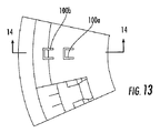
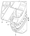
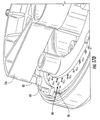
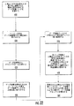
以下、図面について説明する。図1A,1Bは、カバー11および吸入口10pを有するマルチドーズ吸入器10の例を示している。カバー11は、吸入器の上面に拡がっており、マウスピース10mの吸入口10pを覆って下方に延び、次いで、マウスピース10mから後方に向かって、吸入器の底面を覆って延びている。しかし、この吸入器の構成は、単に完全性を目的として示されているにすぎず、本発明の実施形態は、この吸入器の構成に制限されるものではなく、他の形態因子、他のカバー、および他の吸入口構成が用いられてもよい。
The drawings will be described below. 1A and 1B show an example of a
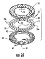
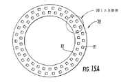
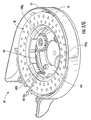
図2Aは、複数のドーズ容器30cを有するドーズリングまたはドーズディスク30を備えているドーズ容器アセンブリ20を示している。図2B,2Eに示されているように、いくつかの実施形態では、ドーズリングまたはドーズディスク30は、周方向に離隔された複数の貫通開口30aを備えることができる。これらの開口30aは、ドーズ容器30cの一部をなすものである。図2Eに示されているように、ドーズ容器30cは、ドーズ容器開口30aと、上側シーリング材36および下側シーリング材37と、によって画成されている。
FIG. 2A shows a
図示されているように、ドーズ容器アセンブリ20は、下側気道ディスク40および上側気道ディスク50を備えている。他の実施形態では、ドーズ容器アセンブリ20は、ドーズ容器ディスク30、および下側気道ディスク40または上側気道ディスク50の1つのみを備えていてもよい。このような構成では、ディスク30の他の側に、他の種類の気道、例えば、制限されるものではないが、固定されたまたは広域に及ぶ上側または下側気道が、上側または下側気道ディスク50,40のいずれかによってもたらされる個々の気道と共に用いられてもよい。また、本明細書に記載されている上側および下側気道ディスク50,40は、通常の操作におけるのと上下逆になって(すなわち、不注意によって、通常と異なって)用いられることも見込まれている。具体的には、下側気道ディスクが上側気道ディスクになり、上側気道ディスクが下側気道ディスクになって、用いられることも考慮されている。
As shown, the
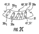
図2A,2Bに示されているように、下側および上側気道ディスク40,50は、それぞれ、周方向に離隔された複数の気道通路41,51を備えている。典型的には、ディスク40,50は、1つのドーズ容器30cに対して、1つの通路41,51を備えている。しかし、他の実施形態では、例えば、図2Cに示されているように、ディスク50’,40’の1つまたは両方からの各々の気道通路51,41が、2つ以上の異なるドーズ容器30cに連通していてもよい。この構成によって、関連する気道通路51または41の1つおよび/またはそれらの気道通路対と連通している2つ以上のドーズ容器30cからの2種類以上の異なるドライパウダーの(同時)組合せ送達が可能になる。従って、本発明の実施形態は、一回の送達中に、単一のドーズ容器30cからのドーズのみを放出するように示されているが、他の実施形態では、この吸入器は、2つ以上のドーズ容器30cが送達用のそれぞれの気道通路41,51を用いることによって、組合せ薬剤を投与することが可能である。
As shown in FIGS. 2A and 2B, the lower and
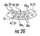
ディスク30は、真っ直ぐに並んで配置された2連の容器30c1,30c2間に、周方向に離隔された単一のドーズ容器30cを有していてもよいことにも留意されたい。しかし、いくつかの実施形態では、ドーズディスク30は、対応する気道通路41/51(典型的には、通路対)と共に半径方向に互いに離隔された2連(以上)の容器30c1,30c2を有していれば、短い通路41,51または単一のドーズ容器30cのいずれも必要としないように構成されていてもよいことが見込まれている。ドーズ容器は、真っ直ぐに並んだ対(以上)の同心列に配列されていてもよい。いくつかの実施形態では、組合せ送達構成として、各気道通路41/51の下または上に位置するように構成されたドーズ容器30c1,30c2を用いることができるが、この場合、気道通路41/51は、図2Gに示されているように、ディスクの内周の近くのドーズ容器から(該内周側のドーズ容器に対して)互い違いに配置された外周の近くのドーズ容器に向かって傾斜して延在するようになっていてもよい。しかし、1つまたは複数の気道通路は、互い違いになっていない中心線を有する2つ以上のドーズ通路の上または下に延在していてもよい。
It should also be noted that the
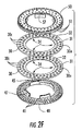
他の実施形態では、図2Fに示されているように、2つ以上のドーズディスク30が積層されていてもよい。これらのドーズディスク30は、気道通路ディスク40,50間に挟み込まれていてもよいし、または単一軌道ディスク40/50と共に用いられるようになっていてもよい。この場合、突刺具は、2つ以上の積層されたドーズディスクのそれぞれの容器を開封し、2つ以上の積層されたドーズ容器から薬剤を放出させ、1つまたは2つの通路41,51を用いる吸入を可能とするように構成されているとよい。
In other embodiments, two or
他の実施形態では、それぞれの気道通路51,41に連通している互いに異なるドーズ容器によって、1つのドーズ容器30c1がドライパウダーを気道通路41および/または51に放出し、次いで、他のドーズ容器30c2がドライパウダーを気道通路41および/または51に再び放出することも可能である。このように、本発明の実施形態では、気道通路41,51のいくつかまたは全てが、一回または2回用いられることが可能になっている(さらに多数回利用する他の構成も可能である)。
In other embodiments, the different dose container to each other in communication with the
いくつかの実施形態では、気道通路41,51は、いったん吸入器が、ドーズ容器の外側リングが気道ディスクと真っ直ぐに並ぶ他の位置に、再び割り出されたなら、それぞれの気道通路に存在しているドライパウダーを利用者に放出することができないような気道を画成している。これらの通路は、(前述したように、2回使用構成が用いられ、該気道通路を用いて、他のドーズがもう一回だけ放出されてもよい場合を除外して)、過量投与を防ぐために、本発明のいくつかの実施形態による漏出を阻止する「シンクトラップ(sink trap)」を有するように、構成されていてもよい。
In some embodiments, the
2つの気道ディスク、例えば、下側および上側ディスク40,50の両方が用いられる場合、吸入装置10は、ディスクが倒置されている場合でも、操作することができ、かつ同一の過量投与防止機能を有するように、構成することができる。ドーズ容器30cが開封されたときの吸入器10からのドライパウダーの漏出は、重力の影響を受けることがある。例えば、通常の左右半円四辺形または楕円形のマウスピース形状の場合、2つの主な装置の向き(表面側が上になる向きおよび表面側が下になる向き)があるが、本発明の実施形態では、これらの向きのいずれでも、吸入装置を操作することが可能である。例えば、図2Aに示されている実施形態では、これは、各ドーズ容器30c(または組合せ薬剤の送達が望ましい場合には、複数のドーズ容器)用の個々の気道区域を対応する目標ドーズ容器30cの上と下の両方に配置することによって、達成されることになる。
If two airway discs are used, for example both the lower and
図2A,2D,3Aは、ドーズ容器ディスク30が、60個のドーズ容器30cを備えることができることを示しており、図3Bは、ドーズ容器ディスク30が、30個のドーズ容器30cを備えることができることを示している。これよりも多いかまたは少ない数のドーズ容器が用いられてもよい。
2A, 2D, and 3A show that the
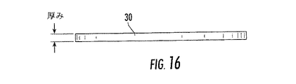
図2Eは、シーリング層36,37が環状の平坦リングとして構成されているとよいことを示している。図示されているように、これらのシーリング材36,37を用いて、ドーズディスク30の上面および底面を密封することができる。シーリング層36,37は、同じ材料であってもよいし、異なる材料であってもよい。シーリング層36,37の例として、箔、一種または複数種のポリマーおよび/または一種または複数種のエラストマー、または他の適切な材料、またはこれらの材料の組合せ、例えば、積層品が挙げられる。典型的には、シーリング層36,37は、箔からなる薄い柔軟シーリング層である。
FIG. 2E shows that the sealing layers 36, 37 may be configured as an annular flat ring. As shown in the drawing, the top and bottom surfaces of the
シーリング層36,37は、(用いられる場合)、図2Eに示されているように実質的に連続的なリングとして設けられてもよいし、または開口30aの上および下に配置可能な個別のシーリング材の帯片またはスポット片として、ドーズ容器ディスク30に取り付けられてもよい。他の実施形態では、シーリング層は、ドーズディスク30の1つの主面にのみ設けられていてもよい。この場合、開口30aは、貫通孔ではなく、片側が閉鎖されていることになる(図示せず)。さらに他の実施形態では、ドーズディスク30は、ブリスター構造130(図17A)を有していてもよい。
The sealing layers 36, 37 (if used) may be provided as a substantially continuous ring, as shown in FIG. 2E, or may be a separate one that can be placed above and below the
図2A,2D,3A,3Bは、ドーズ容器ディスク30が少なくとも1つの割出しノッチ34を備えることができることも示している。これらの割出しノッチは、周方向に離間した複数の割出しノッチ34として、図示されている。ディスク30,40,50を互いに対して位置決めするのを補助するために、他のディスク40,50の1つの嵌合部品を用いることができる。例えば、気道ディスク40,50の1つ、典型的には、下側ディスク40は、半径方向外方に延在しているタブ45(図4A,6)を有する内壁を備えているとよい。このタブ45は、通路41,51をドーズ容器30cと真っ直ぐに並べて位置決めするために、ノッチ34の1つと真っ直ぐに並べられ、かつ該ノッチ34に係合されるようになっている。他の位置合わせ手段、例えば、ここに記載されているノッチ/タブ構成と逆の構成(例えば、気道ディスク40,50の一方または両方がノッチを有し、ドーズ容器ディスク30がタブまたは他の部品を有する構成)が用いられてもよい。
2A, 2D, 3A, 3B also show that the
図2B,2D,3A,3Bに示されているように、ドーズ容器30cは、1列または複数列に沿って互いに周方向に離間するように配置されているとよい。図3Aに示されているように、ドーズ容器30cは、互い違いの同心列、具体的には、ディスクの中心から第1の半径にある前列31および第1の半径と異なる第2の半径にある後列32に配置されている。ドーズ容器30cは、後列のドーズ容器30cの中心線が前列のドーズ容器30cの中心線から周方向においてある距離だけずれるように、配置されていてもよい。図3Aに示されているように、各列におけるドーズ容器30cは、距離「D」だけ互いに離間している。前列のドーズ容器の中心線に対する後列のドーズ容器の中心線の位置ずれは、「D/2」である。ドーズ容器ディスク30は、成形されたポリマー、コポリマーまたは混合物、およびその誘導体であってもよいし、金属またはその組合せであってもよいし、または十分な耐湿気性をもたらすことができる材料であってもよい。
As shown in FIGS. 2B, 2D, 3A, and 3B, the
ドーズ容器ディスク30は、約50mm−100mmの間、典型的には、約65mmの外径、および約2mm−5mmの間、典型的には、約3mmの厚みを有することができる。ディスク30は、環状オレフィン(COC)コポリマーからなっているとよい。開口30aは、約2mm−5mmの間、典型的には、約3mmの直径を有することができる。また、(ディスク30を形成するのに成形プロセスが用いられる場合)、離型を容易にするために、図3Dに示されているように、ドーズ容器30cの側壁30wは、各々、約1°−3°の間、典型的には、約1.5°の角度または傾斜を有するとよい。ドーズ容器30は、小型吸入器の全体の大きさに対して所望の数のドーズをもたらすと共に、湿気進入からパウダーを保護することができるように、構成されている。個々のドーズ容器開口30aは、パウダーの湿気保護のために十分なシール領域および十分な材料厚みを得るために、互いに離間されている。
The
図2Eに示されている実施形態と同様に、図3Cは、ドーズ容器30cが開口30aの上下のシーリング層36,37によって密封された開口30aによって画成されていることを示している。前述したように、シーリング材36,37は、箔、ポリマーおよび/またはエラストマー、または適切な材料または材料の組合せ、例えば、積層品を含むことができる。パウダー薬剤吸入器10では、薬剤パウダーは、ドーズ容器30cによってもたらされた密閉された耐湿気性空間内に貯蔵されている。
Similar to the embodiment shown in FIG. 2E, FIG. 3C shows that the
本発明の実施形態では、適切なシールをもたらすことができると共に、気道ディスク40,50をドーズリングまたはドーズディスク30をそれらの間に保持して取り付けることを促進することができるドーズ容器アセンブリ20が提供されている。図2D,2Eに示されているように、いくつかの実施形態では、ドーズ容器ディスク30は、ドーズディスク30の上下面(主面)に連続的な層をなすシーリング材36,37を含んでいる。上下気道ディスク50,40は、それぞれのシーリング材に接触し、かつ締り嵌めが可能となるようにドーズディスク20に当接することができる。図2A,2E,6に示されている例示的な取付け特徴部は、気道ディスク40,50をドーズリング30に密嵌合させることによって、空気漏れを低減させることができるようになっている。ディスク40,50は、ドーズリング30を挟み込み、該ドーズリングは、気道ディスク40,50の組立特徴部の係合の深さを設定する「ストッパ(stop)」として機能することができる。本発明の実施形態では、前述したように、ドーズリング30に対して気道ディスク40,50を割り出し、および/または位置決めするための特徴部が設けられている。付加的または代替的に、いくつかの実施形態では、図2E,4Aに示されているように、気道ディスク40,50の一方または両方に配置された比較的簡単な摩擦係合部材、例えば、制限されるものではないが、「潰しリブ(crush rib)」47rを用いることによって、以下にさらに詳細に説明するように、ディスク40,50の取付け具を互いに固定するようになっていてもよい。
In embodiments of the present invention, there is a
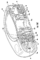
図4Aは、下側気道ディスク40の例を示している。図示されているように、ディスク40は、周方向に離隔された複数の通路41を画成している。互い違いに同心配置されたドーズ容器構成の場合、ディスク40は、交互に配置された長い気道通路42および短い気道通路43を備えることができる。各通路41は、互いに反対側にある端部分41a,41b、具体的には、概してドーズ容器30cに隣接して位置決めされている1つの(実質的または完全に)閉鎖された端部分41a、および1つの開端部分41bを備えている。開端部分41bは、出口10pおよび/またはマウスピース10m(図7A−7C)および/または補給空気ポートまたは通路と1つになり、および/またはそこに隣接して配置されるようになっている。吸気の流れは、いずれの方向であってもよく、開端41bは、ディスク40の内周または外周のいずれかに面するように構成されているとよい(例えば、ディスク40の半径方向最内または半径方向最外に位置決めされているとよい)。通路41は、上方に延在している側壁41wを備えており、互いに隣接している長い通路および短い通路の対が、これらの側壁41wの1つを共有する。任意選択的に、いくつかの通路と真っ直ぐに並んだ特徴部48として図4Aに示されているように、通路41の全てまたはいくつかは、小さい空気抜き孔48を備えていてもよい。空気抜き孔48は、空気が進入することを可能としながら、該空気抜き孔からドライパウダーが流出することを阻止するように寸法決めされている(空気抜き孔48は、説明を容易にするために、いくつかの通路41に対してのみ示されている)。
FIG. 4A shows an example of the
図4A,4Bは、ディスク40が、互いに周方向に離間した上方に延在しているタブ47を有することができることも示している。タブ47の1つは、前述した半径方向(外方)に延在しているタブ45を備えていてもよい。ディスク40は、付加的または代替的(任意選択的)に、周方向に延在している凹部を備えることもできる。凹部は、上側気道ディスク50のタブと真っ直ぐに並んで配置され、ドーズディスク30をこれらの間に挟み込むためのものである。タブ47は、任意選択的に潰しリブ47rを備えていてもよい。リブ47rは、どのような追加的な取付け手段も必要とすることなく、3部品ドーズアセンブリ20を十分な力で保持するように、上側気道ディスク50のタブ57と嵌合するようになっている。
4A and 4B also show that the
図4C,18D,20は、どのドーズが投与されているかまたはどれほどのドーズが吸入器内に残っているかを利用者が視覚的に確認することができるように、ディスク40がドーズ印44を備えることもできることを示している。ドーズ印44は、吸入器ハウジングのドーズ読取り開口と真っ直ぐに並んで配置されているとよい。これによって、利用者は、各ドーズが投与位置に割り出されたときまたは次に投与位置に割り出されるとき、肉眼で確認できるドーズ印/情報を視覚的にチェックすることができる。ドーズ印44は、付加的または代替的に、上側ディスク50に配置されてドーズ読取り開口(図20)と真っ直ぐに並んで配置されていてもよいし、または上側および下側気道ディスク50,40の両方に配置されていてもよい。図18Dは、ドーズ印44が、下側ディスク40の下面の外周縁に沿って配置され、通し番号1−60が付されていることを示している。いくつかの実施形態では、図20に示されているように、印44の番号は、ドーズ容器が交互の列において順次開封される場合、ドーズ容器30の列間を交互移動しつつ順次大きくなるように付けられているとよい。例えば、外側列のドーズ容器に番号1を付け、内側列のドーズ容器に番号2を付け、外側列のドーズ容器に番号3を付け、以下、同様に交互に番号を付けることができる(または、この逆に、番号が付されてもよい)。しかし、開口の並び(およびディスクにおけるドーズの数)に依存して、他のドーズ番号付けのパターンが用いられてもよい。すなわち、この番号付けは、2列のドーズ容器が用いられる場合、吸入器が、1つの列のドーズ容器を開封し、次いで、他の列の隣接するドーズ容器を開封し(例えば、内側リングのドーズ容器から外側リングのドーズ容器または外側リングのドーズ容器から内側リングのドーズ容器に交互にドーズ容器を開封し)、この開封の順序を繰り返す場合に適している。しかし、他の実施形態では、内側列のドーズ容器または外側列のドーズ容器の全てを開封し、次いで、他の列のドーズ容器を開封することもあり、または内側列および外側列のドーズ容器を異なる交互パターンに従って開封することもある。従って、この場合、このような開封の順序に応じて、ドーズ番号の印がディスク40および/または50上に付されるとよい。
4C, 18D, and 20 show that the
図5Aは、上側気道ディスク50の例を示している。この実施形態では、上側気道ディスク50は、その通常の使用位置から倒置されて(図2Aに示されている配向に対して倒置されて)示されている。図示されているように、ディスク50は、周方向に離隔された複数の通路51を画成している。互い違いに同心配置されたドーズ容器構成の場合、ディスク50は、交互に配置された長い気道通路52および短い気道通路53を備えることができる。各通路51は、互いに反対側にある端部分51a,51bを備えている。閉鎖した部分または実質的に閉鎖した部分51aは、典型的には、ドーズ容器30cに隣接して配置されている。吸気の流れは、いずれの方向であってもよく、開端51bは、ディスク50の内周または外周のいずれかに面するように構成されているとよい(例えば、半径方向最内または半径方向最外のいずれかに位置決めされているとよい)。他の(開)端部分51bは、出口流路ポート10pおよび/またはマウスピース10mおよび/または補給空気ポートまたは通路と1つになり、および/またはそこに隣接して位置決めされている。通路51は、下方に延在している側壁51wを有しており、互いに隣接している長い通路および短い通路の対が、これらの側壁51wの1つを共有する。任意選択的に、図5Aにおいて特徴部48に関して破線によって示されているように、通路51の1つまたは全ては、小さい空気抜き孔48を備えていてもよい(図では、説明を容易にするために、いくつかの通路に対してのみに示されている)。空気抜き孔48は、空気が進入することを可能としながら、該空気抜き孔からドライパウダーが流出することを阻止するように寸法決めされている。
FIG. 5A shows an example of the
図5Aに示されているように、各通路51は、開口55を備えることができる。開口55は、各ドーズ容器30cの上に位置するように(各ドーズ容器30cと真っ直ぐに並ぶように)構成されている。ドーズ容器30cの上側シーリング層36が、開口55の下に位置している。開口55は、突刺(例えば、薄切または穿刺)機構が該開口を通って、シーリング層36,37(図3C)を開封することを可能とするものである。図5Aに示されているように、上側ディスク50は、1つまたは複数の割出しリブ58および/または内周ギア歯59または他の特徴部を備えることもできる。これらの特徴部は、吸入器内において、ディスクを回転させて、該ディスクを割り出すことを可能とするものである。割出しは、異なるドーズ容器30cを投与位置に供給し、および/またはドーズ容器30cを開封するために、突刺機構を目標とする投与用ドーズ容器の上に位置決めするために、行われることになる。他の実施形態では、これらの回転/位置決め機構の一方または両方(または異なる特徴部)が、(図示されていないが)、下側ディスクまたはドーズディスクに設けられていてもよい。
As shown in FIG. 5A, each
図5Bは、ディスク50が、図5Aに示されているような4つのタブに代わって、3つのタブ57を備えていてもよいことを示している(この実施形態では、下側気道ディスク40も、4つのタブに代わって3つのタブを備えることができる、図4B,4C参照)。タブ57の1つは、タブ57の内周面上に示されている垂直方向に延在する位置決めタブ56を有していてもよい。位置決めタブ56は、上側ディスク50上に位置していてもよく、吸入器ハウジング内に固定された突刺機構と関連付けられた突刺フレームと協働作用するように構成されていてもよい。具体的には、位置決めタブ56は、該フレームと真っ直ぐに並んで配置され、ドーズ番号(例えば、1)が付された最初の正確な位置を設定し、割出しがディスクアセンブリ20内のドーズの番号を超えることを阻止するようになっている。換言すれば、位置決めリブ56は、吸入器ハウジングまたはそこに取り付けられた部品と協働し、ディスクアセンブリ20の初期位置を設定するようになっており、ディスクアセンブリ20が一回を超えて(例えば、360°を超えて)回転することを停止するために用いられるとよい。他の実施形態では、これらの機能は、代理人ドケットNo.9336−38によって特定されている同時係属中の共有に係る米国特許出願第XX号に記載されているドーズカウンターのような代替的特徴部または代替的構成部品によって、もたらされるようになっていてもよい。なお、この内容は、参照することによって、あたかも完全に記載されているかのように、ここに含まれるものとする。
FIG. 5B shows that the
吸入器10内のディスクアセンブリ20の割出しは、ドーズごとに約6°(360°の一回転によって、60個のドーズ分を投与することができる60ドーズの各々に対して約6°)とすることができる。
The indexing of the
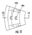
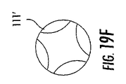
図5Bは、開口55が、突刺具100の形状に対応する幾何学的形状を有するように構成されていてもよいことを示している。開口55は、突刺具100(図20)を緊密に包囲するように構成されているとよい。突刺具100は、溝付き突刺具とすることができる。図示されているように、開口55は、該開口の形状に対応する3つのローブ付き(溝付き)突刺具111(図19C/19D)を密嵌合して受け入れるために、3つのローブ55lを有する。溝付き突刺具は、他の数のローブ、例えば、図19Fに示されているように、互いに周方向に離間した4つのローブ111’を有していてもよく、この場合、開口55は、対応する4つのローブ形状を有することができる。これらのローブ55lは、内側列および外側列において、異なる配向、例えば、180°回転した配向とすることができる(図20参照)。
FIG. 5B shows that the
図2A,6は、一体に取り付けられたドーズ容器アセンブリ20を示している。図2B, 4A,5Aは、例示的なディスク構成部品30,40,50を示している。ディスク50のタブ57がディスク40の空間49内に嵌入され、ディスク40のタブ47がディスク50の空間59内に嵌入され、潰しリブ47rが、(用いられる場合)、タブ57の外縁に堅固に当接することになる。これによって、比較的容易な「圧入(press-fit)」方法によって、これらの部品を、ドーズディスク30をそれらの間に挟み込み、面一になる嵌合が得られるように、互いに摩擦係合させることができる。ドーズ容器ディスク30は、前述したように、ドーズ容器リング30の位置合わせノッチ34の1つと係合する(半径方向外方に延在している)タブ45を介して、上側および下側気道ディスクと真っ直ぐに並んで配置されることになる。しかし、他の位置合わせ特徴部または他の印と共に、他の取付け構成が用いられてもよい。
2A and 6 show the
上側および下側気道ディスク50,40は、(これらの両方が用いられる場合)、ドーズ容器ディスク30に取り付けられてもよいし、または上側および下側気道ディスク50,40は、これらのディスクによって画成される気道経路内の間隙を減少させるように、ドーズディスク30をそれらの間に挟んで、一緒に取り付けられてもよい。ディスク30は、気道ディスク40,50の取付け特徴部に対するストッパとすることができる。シーリング材36,37を有するディスク30は、どのような取付け特徴部も必要とすることなく、実質的に平坦な上側および下側主面を有することができる。上側気道ディスク50の下側部分および下側気道ディスク40の上側部分は、ドーズ容器ディスク30のそれぞれの背向主面上のシーリング材および/またはドーズディスク30の主面に対してぴったりと配置させることができる。従って、取付け特徴部/構成部品は、上側および下側ディスク50,40上のみに設けられており、これによって、他の組立構造における公差によって生じる隙間を生じることなく、ディスク30,40,50間にぴったりと密着した十分な気密界面をもたらすことができる。接着剤を用いることなく実質的に気密の界面をもたらすこの圧入取付けは、有利であり、費用効率が高い。しかし、前述したように、他の取付け構成、例えば、超音波溶接、接着、レーザ溶接、他の摩擦嵌合および/または嵌込構成、およびその組合せが用いられてもよい。また、ドーズ容器30cの方を向いている気道通路の壁の接続領域とディスクのドーズ容器30cの上および/または下のシーリング層36,37との間に、シール(Oリング、ガスケットなど)が用いられてもよい。
The upper and
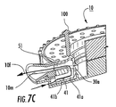
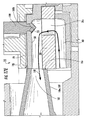
図7A−7Cに示されているように、操作時において、互いに位置合わせされた半径方向に延在している上側および下側通路41,51の対が、各ドーズ容器30cの上および下に位置している。これらの通路41,51は、開封されたドーズ容器30cおよび開口30aを介して、互いに流体連通することになる。すなわち、図7Aに示されているように、突刺機構100が前進し、上側および下側シーリング層36,37(図2E,3C)をそれぞれ突き刺すことになる。突刺機構100は、下側気道通路内に突き出し、該通路内に保留されるように構成されていてもよいし、または下側シーリング材を開封した後で投与前に、(部分的または完全に)後退するようになっていてもよい。また、シーリング層を突き刺すために下方に突き出している状態が示されているが、突刺機構100は、底側から上方に突き出すように構成されていてもよい。いずれにしても、いくつかの実施形態では、突刺機構100は、開口30aおよび/または上側ディスク(または下側ディスク)の開口55を塞ぐように、構成されているとよい。
As shown in FIGS. 7A-7C, in operation, pairs of radially extending upper and
図7Bに示されているように、その後、突刺機構100は、突刺機構の構造に依存して、部分的または完全に後退するか、または下側(または上側)気道通路内に突き出した状態で保留されることになる。しかし、典型的には、突刺機構100は、上側ディスク50(または底側から突き刺す場合には下側ディスク40)の開口55を塞ぎ、および/または該開口55を塞ぐことができる部材と協働作用するか、または突刺機構100および/または協働部材が孔/開口55(図2A,5)を実質的に封鎖、すなわち、閉塞(および/または密封)することによって、この通路55を塞ぐように、構成されている。このようにして、もし吸入器が倒置されても、パウダーは、突刺機構100によってもたらされた閉塞によって、通路51から外に漏出することが阻止される。気流経路10fの方向は、ドーズ容器30cの上から下に向かう方向であってもよいし、またはその逆の方向であってもよい。ドライパウダーを伴う気流10fの方向は、内周から外周に向かう方向であってもよいし、またはその逆の方向であってもよい。図7B,20は、(矢印によって示されている)例示的な気流経路10fの方向を示している。この気流経路10fによって、空気は、ディスクアセンブリ20の外周の底側通路の開端41bから流入し、開口30aを上方に通過し、ディスクアセンブリ20の上側通路51の開端51bからマウスピース10mに流れることになる。通路の出口部分または開端部分41b,51bは、いずれも、図7A−7Cに示されているようなディスクアセンブリ20の外周ではなく、内周に面していてもよい(例えば、図17A参照)ことにも留意されたい。
As shown in FIG. 7B, the
投与の後、突刺機構100は、図7Cに示されているように、完全に後退し、ドーズ容器アセンブリ20は、投与位置に回転され、および/または突刺機構100は、異なるドーズ容器30cを開封するように作動されることになる。操作時に、ドーズ容器アセンブリ20は、例えば、マウスピース10mと1つになる出口流路部材10fmに対して、気道通路41および/または51を密封するかまたはこれらに対して密着した出口流路をもたらすために、半径方向外方に押されるようになっていてもよい。
After administration, the
図17Aは、気流出口10l(または短い経路10sおよび/またはマウスピース10m)とディスクアセンブリ20との間に十分な気密経路をもたらすために、Oリングのようなシール129が用いられてもよいことを示している。他のディスクの出口気流経路の密封または閉塞構成が用いられてもよい。これらの例については、以下に説明する。
FIG. 17A shows that a
いくつかの実施形態では、突刺具100の部分的な後退によって、吸入器10が倒置位置で用いられるときにパウダーが気道通路から脱落するのを阻止または防止することができる。例えば、図17A,17Eに示されているように、この操作を容易にするために突刺具ヘッド100hと上側気道ディスク50のアクセス開口55との間の隙間は、小さくなっているとよく、および/または突刺具ヘッド100hをぴったりと受け入れるようになっているとよい。突刺機構100は、高レベルの位置決め精度で操作されるように、構成されているとよい。具体的には、突刺具100は、ディスク30によって保持されている(各列に配置された、典型的には、列間で交互に配置された)各ドーズ容器30cのアクセス開口55と真っ直ぐに並んで、該アクセス開口に手際よく進入することができるように、構成されているとよい。いくつかの実施形態では、マウスピース10mに関連付けられた固定気道と回転している回転ディスクサブアセンブリ20との間の接合部10j(図17A,17E)における空気漏れを低減または排除することによって、一定のドーズ送達を可能とし、かつ漏れが存在する場合も、その漏れをドーズ間で一定にすることが可能である。図17Aに関して説明したように、追従シール129を用いることによって、この機能を果たすことができる。また、前述したように、ディスク20が、マウスピース10mに向かって付勢されてもよい(例えば、接合部10j/マウスピース10mに向かって半径方向に押されてもよい)。
In some embodiments, partial retraction of the
図17B−17Eは、レバーアセンブリ80を用いて、ディスクアセンブリ20をマウスピース10mに向かって付勢することができる吸入器10の実施形態を示している。この付勢によって、突刺のためのディスクアセンブリ20の正確かつ繰り返し可能な位置決めを助長することができると共に、マウスピース接合部10jにおける空気漏れを制御することができる。空気漏れに関して、吸入器の実施形態では、ディスクとマウスピースとの緊密な連結は、吸入の時期と一時的に同期して行われ、他の時期、例えば、ディスクアセンブリ20の割出し中には、吸入器は、吸入器10内のディスクアセンブリ20の回転を容易にするために、緩い嵌合を可能とするようになっている。この実施形態では、マウスピース10mは、ディスクアセンブリ20の外周に配置されており、ディスクアセンブリ20の出口もディスクアセンブリの外周に配置されている。他の実施形態では、気道通路の出口は、ディスクの内周に配置されていてもよいし、またはそれ以外に構成されていてもよく、またはそれ以外に配置されていてもよい。
17B-17E illustrate an embodiment of the
図17Bに示されているように、レバーアセンブリ80は、上側気道ディスク50の上面と連動するレバーアーム81を備えている。レバーアーム81は、ディスクアセンブリ20の外周に近接して離間するように、該外周から距離を隔てて下方に延在している。レバーアセンブリ80は、フィンガー部82も備えている。フィンガー部82は、ディスクアセンブリ20の上方に配置されており、ディスクアセンブリ20に向かって下方に延在している。図示されている実施形態では、レバーアセンブリ80は、負荷ポスト84も備えている。負荷ポスト84は、ディスクアセンブリ20の外周の近くに配置されている。レバーアーム81は、フィンガー部82を受け入れるように構成された凹部83を備えている。フィンガー部82が凹部83内に位置すると、ポスト84がディスク20を半径方向内方に押し、吸入時に緊密な接合部10jを生じさせることになる(図17E)。凹部83は、開いた周辺形状を有することができ、フィンガー部82は、該凹部に対して摺動可能に出入りすることができる。レバーアーム81は、(凹部83に向かう方に傾斜した)斜面を画成することができる。この斜面は、フィンガー部82に摺動可能に係合し、これによって、フィンガー部82を凹部83に向かって移動させるように導くことができる。
As shown in FIG. 17B, the
レバーアセンブリのフィンガー部82は、レバー12n(図1Bでは、10lの部番が付されている)に取り付けられており、典型的には、利用者によるレバー12nの作動時に、吸入器ハウジング内において、フレーム12に対して回転するようになっている。レバー12nが「作動(投与)」位置から戻ると、フィンガー部82は、凹部83から引き出され、これによって、ディスクアセンブリ20は、自在に回転して、次の投与位置への割出しを行うことができる。
The
典型的には、吸入中、負荷ポスト84は、マウスピース10mと半径方向において反対側(実質的には、直径方向において反対側)に位置している。レバーアーム81およびポスト84は、回転しない。この構成部品は、吸入器ハウジングに取り付けられたフレーム12に取り付けられている。フィンガー部82は、フレーム12(およびレバーアーム81)に対して回転することになる。
Typically, during inhalation, the
図17Bに示されているように、フィンガー部82は、割出し中の自由な回転を可能とするために、レバーアセンブリ80の移動サイクルのこの期間中、レバーアーム81と接触しないようになっている。図17Cは、凹部83に向かって移動しているフィンガー部82を示している。図17Dは、凹部83内に位置してディスクアセンブリ20を出口流路部材10fmに向かって付勢しているフィンガー部82を示している。吸入時において、フィンガー部82は、その最大移動限界まで前進している。ディスクアセンブリ20の割出し(回転)が行われている間、フィンガー部は、その移動経路のどこかに位置している(アームは、静止している)。従って、図17Dの矢印によって示されているように、レバーアセンブリ80は、適切な時期(吸入時)に、フィンガー部82が最も遠くまで移動しており、ディスクアセンブリ20を付勢し、接合部10jを密封し、その一方、割出し中、(典型的には、吸入時以外)、ディスクアセンブリ20を付勢することなく、その自由な移動を可能とするようになっている。
As shown in FIG. 17B, the
製造中、ディスクアセンブリ20のドーズディスク30の直径と上側気道ディスク50の直径との間に、誤差による不整合が生じる可能性があることが分かっている。図17Eに示されているように、ディスクアセンブリ20がマウスピース10mに付勢されると、これらのディスク30,50の両方の内側または外側の側壁面(図では、外側の側壁面として示されている)が、該マウスピース10mに接触することになる。従って、図17Eに示されているように、より大きな接触面積を有する上側気道ディスク50が、マウスピース10mと連通しているマウスピースまたは出口流路部材10mfに常に接触するようにした場合、ドーズディスク30と重なる箇所において、小さい逃げ10rが、出口流路部材10fm(マウスピース10mのこともある)の近接面内または当接面内に切り取られたような形態またはそれ以外の形態で生じることがある。
During manufacturing, it has been found that there may be a misalignment between the diameter of the
図17F、17Gは、付勢機構180の代替的な実施形態を示している。付勢機構180は、吸入中、ディスクアセンブリ20をマウスピース10mに向かって付勢し、次いで、割出しのためのディスクアセンブリ20の回転を可能とするために、解除または離脱されるようになっている。前述したように、いくつかの実施形態では、吸入器10は、内側列および外側列に交互に並んだドーズ容器から連続的に投薬するために、または該ドーズ容器に連続的にアクセスするために、規定の角回転、例えば、約6°だけディスクアセンブリ20を回転させるように、構成されているとよい。この付勢機構180は、レバーアセンブリ80に関して前述したレバーと同様のレバー10lによって操作されるように構成されていてもよいが、他の構成部品または特徴部を用いて作動されるようになっていてもよい。
17F and 17G show an alternative embodiment of the
図17Fに示されているように、付勢機構180は、ドーズ容器ディスクアセンブリ20の内周の近くに位置するポスト182を備えることができる。ポスト182は、周方向に延在している長孔182s内に配置されているとよい。長孔182sは、ドーズディスクアセンブリ20の内周に向かって半径方向外方に延在している長孔部分183と一体になっている端部分を有する。吸入のための利用者への薬剤の放出(例えば、「投薬(dosing)」)の最中および/または直前に、ポスト182が、長孔部分183に達するまで、長孔182s内において移動し、長孔部分183内において、ポストは、(典型的には、間接的に)ディスクアセンブリ20の内周を押し、(矢印によって示されているように)、ディスクアセンブリ20をマウスピース10mに向かって付勢することになる。なお、図17Fにおける吸入器は、通常の配向から倒置されて示されている。
As shown in FIG. 17F, the
図17Gは、ポスト182が、割出し板またはフレーム184上の静止ポスト182bと連動していてもよいことを示している。図示されている実施形態では、付勢ポスト182は、ポスト182bに接触し、かつ押すことによって、ポスト182bをドーズ容器アセンブリ20に対して半径方向外方に撓ませるように、構成されている。2つのポスト182,182bは、互いに向かって突出するように構成されているとよく、具体的には、一方が上方に突出し、他方が下方に突出するように構成されているとよい。ポスト182bは、典型的には、ドーズディスクアセンブリ20の内周に近接して配置されている。
FIG. 17G shows that the
ポスト182は、典型的には、利用者がアクセスすることができるレバー10lに取り付けられているかまたは連動するようになっている。しかし、ポスト182は、ポスト182を長孔182s内において移動させてディスクアセンブリ20をマウスピース10mに向かって付勢させる他の機構に連動するようになっていてもよい。
The
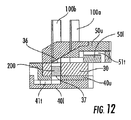
図17Gに示されているように、割出し板184は、割出し器109に関連付けられたギア109gの下方に位置しているとよい。回転ギア109gは、図18Eに示されているように、フレーム部材109f上のマウント110に保持されているとよい。一般的に、ギア109gは、(図18Fにおいて斜面ディスク209の一部とすることができる)割出しポスト109p上の歯109t、およびディスクアセンブリ20上(例えば、図示されているように、下側ディスク40上)のギア歯59aに連動している。割出しポスト109pを回転させることによって、ギア109gが回転し、これによって、ディスクアセンブリ20を割り出すことになる。(吸入器ハウジングの底の近くに位置する)他のギア歯59bは、図18Dに示されている割出し制御アーム109rに連動しているとよく、これによって、ドーズ容器アセンブリを所望の回転量だけ、より正確に回転させることができる。図18D,18Eは、通常の使用時の配向から倒置した配向にある吸入器を示していることに留意されたい。図18Fは、「通常」の使用時の配向にある吸入器を示しており、この配向では、ドーズディスクアセンブリ20は、例えば、図18Cにも示されているように、突刺機構100の下方に位置している。突刺具100は、図18Fに示されているように、フィン状斜面211を有する斜面ディスク209に連動しているとよい。図示されている実施形態では、斜面ディスク209は、突刺具100a,100bと協働し、それぞれの突刺具100aまたは100bをドーズ容器30c内に押し出すようになっている。ポスト182は、典型的には、図17F,18E,18Fに示されているように、利用者がアクセスすることができるレバー10lに取り付けられている。しかし、ポスト182は、ポストを長孔182a内において移動させてディスクアセンブリ20をマウスピース10mに向かって付勢させる他の機構に連動するようになっていてもよい。
As shown in FIG. 17G, the
図17F,17Gに示されている割出し機構109について、図18C−18Fに関して、さらに後述することにする。しかし、他の割出し構造が用いられてもよい。
The
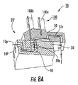
図19Aは、コルク・スクリュー突刺具110を有する突刺機構100の一実施形態を示している。操作時に、コルク・スクリューは、典型的には、回転することなく、垂直方向に真っ直ぐ上下運動し、シーリング層36,37を貫通する所望の開封形状(例えば、円形状)を生じさせるようになっている。他の実施形態では、コルク・スクリューは、突出しおよび/または投与中、回転するようになっていてもよい。図示されている実施形態では、ドライパウダーが気流通路内に供給されている間、コルク・スクリュー突刺具110は、下側通路41に保留されており、コルク・スクリュー110に取り付けられて一緒に上下運動する弾性部材120によって、開口30aが塞がれている。突刺機構100は、2段階の操作、すなわち、(割出しのための)十分な上昇段階の操作および十分な下降段階の操作を行うようになっている。コルク・スクリューの最前部分は、シーリング材(例えば、箔)に所望の切断形状をもたらす形状の先端を有することができる。いくつかの実施形態では、コルク・スクリュー突刺具110は、シーリング材36,37に耳部を有する形状を切り抜き、次いで、この耳部を下方に折り曲げ、ドライパウダーを放出するようになっている。投与中にコルク・スクリュー突刺具110を通路41内に保留することによって、改良された空力学乱流、せん断乱流、または衝撃乱流をドライパウダーにもたらすことができる。弾性部材120は、開口30aを密封または閉塞するのに使用可能な発泡ブロックまたは他の弾性部材(例えば、バネによって付勢される硬質部材または剛性部材)から構成されているとよい。図19Bは、上側および下側気道ディスク50,40の両方を有するディスクアセンブリ20と共に用いられる同様のコルク・スクリュー突刺具110を示している。ポリマープラグおよび/またはエラストマープラグまたは発泡プラグのような弾性および/または柔軟性を有する部材100pを用いて、ディスク開口55を閉塞または密封することができる。
FIG. 19A shows one embodiment of a piercing
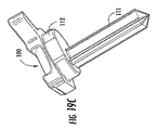
図19C,19Dは、溝付き中実突刺具111を有する突刺機構100を示している。溝は、真っ直ぐな溝形状を有していてもよいし、またはその長さに沿って捩じれ部または部分的な捩じれ部を有していてもよい。後者の場合、例えば、ローブ(lobe)の最大値および最小値が、溝の長さに沿って軸方向に変化するような捩じれ構造であるとよい。溝は、複数のローブ、典型的には、3つまたは4つのローブ、例えば、図19Cに示されているように、3つのローブを備える断面を有することができる。溝付き構造は、図19Eに示されているように、部分的な前方長さ部だけが突き出されるようになっており、この部分的な前方長さ部が、開口55の閉塞または密封を促進するための一定直径の区域に一体化されているとよい。他の実施形態では、中実突刺具または溝付き突刺具の構造は、開口55を覆っておよび/または開口55内に位置するキャップまたはプラグ100p(例えば、図19C参照)と一体化するようになっていてもよい。いくつかの実施形態では、捩じれた溝111が、投与中、ドーズ容器開口30および/または下側ディスク40内に保留されるようになっており、これによって、気道内の乱流および/または衝撃を促進することができる。
19C and 19D show a piercing
図19Dは、溝付き突刺具111が、箔または他のシーリング材料を突き刺すときに回転させることによって、丸孔を形成することができること、または回転することなく真っ直ぐ突き出されてもよいことを示している。他の実施形態では、溝付き突刺具110は、回転させることなく、突き出しまたは前進させることによって、1つまたは複数のシーリング層36,37を突き刺すようになっていてもよい。図19Eは、溝付き突刺具111’が、長さ「L1」を有する溝付き前部分111fを備えており、この溝付き前部分111fが、長さ「L2」を有する実質的に円状の断面を有する中実部分112に一体化されていることを示している。L1は、典型的には、L2よりも長くなっている。長さL1は、中実部分が気道ディスク開口55に係合している状態で、溝付き前部分111fが、ドーズ容器の開口30a内に保留され、および/または同時に下側シーリング材37内に保留されるのに十分な長さ(典型的には、下側シーリング材の直下またはディスク30の下面と同じ高さまたはわずかにその上または下に保留される)のに十分な長さを有することができる。
FIG. 19D shows that the grooved piercing
図19Gは、通路55を閉塞することができる(コルク・スクリュー構造の図19Bに示されているのと同様の)プラグ100pを備えることができる突刺機構100を示している。プラグ100pは、どのような突刺具、例えば、コルク・スクリュー110(図19A)または中実溝付き突刺具111(図19B)、または他の突刺具と共に用いられてもよい。突刺ヘッドは、図19Eに示されているように、投与中、下側通路41内に保留されていてもよい。あるいは、突刺具は、プラグ100pを開口または通路55に対しておよび/またはその上の適所に残して、該プラグ(図示せず)の通路を通って部分的に後退するようになっていてもよい。
FIG. 19G shows a piercing
いくつかの実施形態では、溝付き突刺具111は、その長さに沿って捩じれているローブを有するように構成されていてもよい(図19D)。例えば、溝付き突刺具111は、溝付き突刺具のローブの周辺が旋回するように、その長さに沿って約60°の捩じれを有することができる。(シーリング材に直進する)真っ直ぐな突刺しストローク中、捩じれた溝付き突刺具111は、シーリング材36および/または37に完全に丸い孔を作ることができる。
In some embodiments, the
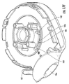
図20は、ディスクアセンブリ20によってもたらされる実質的にU字状の空気経路を示している。「U字」形状は、上側ディスク通路51および下側ディスク通路41によって、形成されている。具体的には、これらの通路41,51が、ディスク本体を横切って半径方向に延在する「U字状」の長辺を画成している。図示されているように、この実施形態では、ディスクアセンブリ20の外周が、気流経路10fの出口および入口の両方を有する。「U字状」の流路(または、いくつかの実施形態では、気流ディスク40,50の1つが用いられている場合、部分的な「U字状」の流路)は、パウダーの解凝集器として機能することができる。粒子は、ドーズ容器30cを出るとき、気道ディスク通路51の対向する壁に衝突し、その結果、薬剤パウダーを解凝集するのに十分な力が得られることになる。
FIG. 20 shows the substantially U-shaped air path provided by the
図20は、吸入気流経路10fに関連付けられた空気流に付随するドライパウダー粒子の軌道10dの例も示している。ドライパウダーがドーズ容器30cから気流経路10fに出た後、気流および空気内の小さいパウダー粒子(10f)は、約90°回転することができるが、重いドライパウダー粒子(10d)は、上側気流ディスク通路51の内壁51wで跳ね返ることになる。この跳ね返りの角度は、徐々に小さくなり、重いドライパウダー粒子は、最終的にほぼ真っ直ぐになって、マウスピース10mから出る。壁51wに対する重いドライパウダーの衝突によって、ドライパウダーの解凝集が促進されることになる。図5Aを再び参照すると、ドーズ容器30が2列に配置されている実施形態では、通路51は、ドーズ容器30が内側列に配置されているかまたは外側列に配置されているかによって、通路51の長さが異なっている。
FIG. 20 also shows an example of a dry
いくつかの特定の実施形態では、気道通路41,51は、交互に配置された短い通路および長い通路を備えている(例えば、図5A参照)。長い通路(これらの通路は、外周に出口が位置している場合は、ドーズ容器が内周に配置されており、内周に出口が位置している場合には、ドーズ容器が外周に配置されている)の長さは、約5mmから約15mmの間、典型的には、約10mmとすることができる。短い通路の長さは、約3mm−10mmの間、典型的には、約5mm(例えば、長い通路の長さの約40−70%)とすることができる。各通路41,51の深さ(垂直方向の高さ)は、同じとすることができ、いくつかの実施形態では、異なっていてもよい。通路41,51の例示的な深さは、約1mmから3mmの間、典型的には、約2mmであるが、他の深さが用いられてもよい。
In some specific embodiments, the
吸入器10は、利用者がアクセスすることができるアクチュエータ、例えば、レバー、ノブ、スイッチ、スライダー、クランク、プッシュボタン、または他の機械的および/または電磁的装置を備えることができる。アクチュエータは、1つまたは複数のドーズ容器30c(図2B)を吸入口10p(図1B)と流体連通している吸入チャンバ内の投与位置に配置するために、アセンブリ20を回転させて、ドーズリングまたはドーズディスク30を割り出すことを可能とし、および/または(以下にさらに説明するように)、突刺機構100(図7A−7C)が、前列のドーズ容器30cを開封し、次いで、後列のドーズ容器30cを開封し(またはその逆に開封し)、これによって、利用者による吸入のために薬剤を吸入用の気流経路に放出することを可能とする。吸入パウダーを放出するために、密封されているドーズ容器30cが、開封され、気道41および/または51に接続されることになる。気道41および/または51は、吸入器マウスピース10mであってもよい出口流路部材10fmに接続されるか(例えば、図7A−7C,17A,17E,18A参照)または吸入器マウスピース10mに一体にされている。薬剤が、(吸入器がどのように配向しているかに依存して)、通路41または51に入ると、この通路は、「使用(used)」通路とされる。該使用通路内の薬剤は、(もし利用者が適切にかつ時期に適って吸入するなら)送達されることになり、(もし利用者が吸入せずにマウスピースを閉じるかまたはディスクアセンブリ20を割り出したなら)隔離されることになる。「使用」通路は、開封されたドーズ容器30cと共に割り出され、その結果、再び用いることができない。ただし、(図2Cに関して説明したように)、共有通路内の他のドーズ容器に対してのみ、使用通路は、再び用いられることになる。開封されたドーズ容器に残っているどのようなパウダーも、次のドーズ容器が適所に割り出されたとき、気道から分離されている。
The
いくつかの実施形態では、各ドーズ容器30cに隣接する気道通路41または51によってもたらされる気道の部分は、その個々のドーズ容器30cに特有のものである。従って、気道内へのパウダーのどのような流出も、そのドーズ容器が割り出されて、主気道(マウスピース)に接続されている限り、マウスピースおよび利用者にしか利用できない。次のドーズ容器に割り出されると、(接続されていない)隣接する気道部分が活性吸入気道経路に割り出され、これによって、パウダーを該気道部分に流出および/または蓄積させることになる。
In some embodiments, the portion of the airway provided by the
図8A,8Bは、吸入器10の他の実施形態を示している。この実施形態では、上側気道通路51は、「シンクトラップ」51tの経路として構成されていてもよい。この経路は、立ち上がってから下がるかまたはその逆の気流経路の部分を有する。すなわち、図示されているように、経路51tは、開口30aの上に立ち上がって、次いで、ある距離にわたって下方に延在するように変化し、これによって、気道/吸入器からのドライパウダーの付加的な流出抵抗をもたらすことになる。同様に、下側気道通路41は、ドーズ容器開口30aの下流においてある距離にわたって立ち上がることによって「シンクトラップ」41t経路を形成するように、構成されていてもよい。いくつかの実施形態では、気道ディスク(例えば、上側または下側気道ディスク50,40)の1つのみがシンクトラップを有するようになっているが、他の実施形態では、図示されているように、両方のディスク40,50がシンクトラップ41t,51tを有する気道構造を有するようになっている。ドーズ容器アセンブリ20は、該ドーズ容器30cが開封された時点で、互いに流体連通する真っ直ぐに並んだ通路41,51の対を有する。これらの通路41,51の対は、各ドーズ容器30cの上および下に位置しており、シンクトラップ構造41t,51tを有する。シンクトラップ構造41t,51tは、協働して、曲線状(例えば、横向きの略S字形状)の気流経路を形成している。気流経路10fは、外周から内周に延在していてもよいし、または内周から外周に延在していてもよい。
8A and 8B show another embodiment of the
図8A,8Bに示されているように、この実施形態では、突刺機構100は、2つの突刺部材100a,100bを有することができる。一方の突刺部材は、ドーズ容器30cの第1の列を開封するようになっており、他方の突刺部材は、ドーズ容器30cの第2の列を開封するようになっている。
As shown in FIGS. 8A and 8B, in this embodiment, the
図9A−9C,10−14は、本発明の実施形態によるシンクトラップ51t,41t気流経路をなしている上側および下側気道を有する例示的な吸入器構造を示している。図示されているように、突刺機構100は、ドーズ容器アセンブリ20’上を摺動するハウジングに取り付けられた2つの突刺部材100a,100bを備えることができる。ドーズ容器アセンブリ20’は、各ドーズ容器30cが投与位置に割り出されるように、突刺機構100の下方で回転することができる。同様に、ドーズ容器アセンブリ20’は、もし突刺機構がドーズ容器アセンブリ20,20’の下方に位置しているなら、突刺機構の上方で回転することができる。
9A-9C, 10-14 illustrate an exemplary inhaler structure having upper and lower airways that form sink traps 51t, 41t airflow paths according to embodiments of the present invention. As shown, the piercing
図10,12,14は、下側気道ディスク40が、2つの構成部品、具体的には、曲線状のシンクトラップ経路41tを画成するように取り付けられた上側部材40uおよび下側部材40lを備えることができることを示している。同様に、上側気道ディスク50は、曲線状のシンクトラップ経路51tを画成するように取り付けられた2つの構成部品、具体的には、上側部材50uおよび下側部材50lを備えることができる。特定の実施形態では、ドライパウダーは、予計量されたドライパウダー200として供給されており、シーリング層36,37間の開口30a内に密封されているとよい。図10に示されているように、上側部材50uは、タブ150tを備えることができる。タブ150tは、位置合せおよび/または取付けのために、気道ディスク50の下側部材50lの長孔150sに係合するようになっている。
10, 12, 14 show an
図12は、(突刺部材100bによって開封される)外側列31のドーズ容器30cおよび関連付けられた曲線状気流経路41t,51tを示している。図14は、内側列32のドーズ容器30cを開封する位置にある突刺部材100aを関連付けられた気流経路41t,51tと共に示している。
FIG. 12 shows the
図15A,15B,16は、ドーズ容器30cに用いられる2列の開口30aを有するドーズ容器ディスクまたはリング30の例を示している。ドーズ容器ディスク30は、比較的薄くすることができ、例えば、約2mm−4mm厚みとすることができる。ドーズ容器の開口30aは、内側列32が外側列31から少なくとも約2mm離れるように、かつドーズ容器の内側列および外側列がそれぞれの周辺から約2mm内方に離間するように、構成されているとよい。この間隔によって、十分な耐湿気透過性および/または耐酸素性がもたらされることになる。
15A, 15B, and 16 show an example of a dose container disk or
図17Aは、図18Aにおける短い流路と比較して、長い出口空気経路10lを有する吸入器10の実施形態を示している。この実施形態では、気道ディスクは、開端41b,51bがディスクの外側ではなく、内側の方を向いて開くように、通路41,51を配向させている。図17Aは、ドーズ容器ディスク30がブリスター130を有するように構成されていてもよいことも示している。
FIG. 17A shows an embodiment of the
図17Aは、突刺機構100が、回転突刺具ヘッド102を備えていてもよいことも示している。回転突刺具ヘッド102は、内側列のドーズ容器30cを突き刺し、次いで、回転して、外側列の隣接するドーズ容器30cを突き刺すように構成されている。
FIG. 17A also shows that the piercing
図18Aは、吸入器10が突刺機構100を有するように構成されていてもよいことを示している。突刺機構100は、半径方向に移動し、1つ列のドーズ容器30cを開封し、次いで、半径方向内方または半径外方に移動し、他の列のドーズ容器30cを開封するようになっている。ドーズ容器アセンブリ20および/または気道ディスク40,50の1つ以上およびドーズ容器ディスク30は、前述したように、十分な密シールをもたらすために、(一緒にまたは個別に)、軸方向または他の方向において、出口気流経路の1つまたは複数の壁に付勢されるように、構成されていてもよい。図18A,18Bは、吸入器10が、上側ディスク50の内周のギア歯59と協働作用する割出し機構109を備えることができることも示している。アセンブリ20を回転させて、異なるドーズ容器30cを投与位置に配置するために、他の割出し機構が用いられてもよい。
FIG. 18A shows that the
図18Cは、吸入器10が、2つの突刺具100a,100bを備える突刺機構100を有するように構成されていてもよいことを示している。突刺具100a,100bの一方は、内側列のドーズ容器を突き刺すようになっており、他方は、外側列のドーズ容器を突き刺すようになっている。典型的には、突刺機構100は、外側列または内側列のドーズ容器を突き刺し、次いで、他の列のドーズ容器を突き刺すように、構成されている。突刺具100a,100bは、上下に往復運動し、それぞれのドーズ容器を開封するようになっている。ドーズ容器アセンブリ20および/または気道ディスク40,50の1つ以上およびドーズ容器ディスク30は、十分な密シールをもたらすために、(一緒にまたは個別に)、軸方向または他の方向において、出口気流経路の1つまたは複数の壁に付勢されるように、構成されていてもよい。
FIG. 18C shows that the
図18C−18Eは、吸入器10が割出しポスト109pと協働作用するギア109gを有する割出し機構109を備えており、ディスクアセンブリ20のギア歯59aが下側ディスク40の内周に配置されていることも示している。図18Dは、図18Cに示されている通常の使用時の配向から倒置して示されている。図18C−18Eは、下側気道ディスク40が、近接して重ねられた2つのギア歯59a,59bを備えることができることも示している。一方のギア歯59aは、ポスト109pおよび関連付けられた割出しギア109gと協働作用するようになっている。他方のギア歯59bは、図18Dに示されているように、アーム109rを用いて、さらに精緻な位置決めをもたらすことができるようになっている。アセンブリ20を回転させて、異なるドーズ容器30cを投与位置に配置するために、他の割出機構が用いられてもよい。2連突刺具100a,100bは、斜面ディスク209の斜面と協働作用することができる。斜面ディスク209は、2つの同心列上に周方向に位置ずれしたフィン211を有することができる。これらのフィン211は、それぞれの突刺具を該フィンとの接触によって下方に押すようになっている。割出し器および2連突刺具のさらなる説明は、代理人ドケットNo.9336−38によって特定されている同時係属中の共有に係る米国特許出願第XX号に記載されている。この内容は、参照することによって、あたかも完全に記載されているかのように、ここに含まれるものとする。
18C-18E, the
いくつかの実施形態では、マウスピースポート10pおよび空気入口(図示せず)は、約12mm−127mm(約0.5インチ−5インチ)の間の距離だけ互いに離間していてもよい。吸入器10は、(吸気口が配置されている箇所から吸入ポート10pまでが測定されるものとして)、比較的短い吸気経路、例えば、図7A−7C,18A,18Cに示されているように、約12mm−25.4mmの間の吸気通路、または図17Aに示されているような長い空気経路、典型的には、約50mm−127mm(約2インチ−5インチ)間の空気経路を有するとよい。短い空気経路は、ドライパウダー放出位置と(吸入マウスピース(図示せず)と1つになっている凝集を阻止する乱流促進セグメントを有する)吸入マウスピースとの間に延在している短い管状空気経路を含むように、画成されているとよい。長い空気経路は、吸入器の主部分、すなわち、吸入器の幅または長さの実質的に全てを横切って延在しているとよい。流路の内面/形状は、衝撃面として作用する内面での旋回気流の跳ね返りを助長するために、多角形とすることができる。適切な乱流促進構造のさらなる検討については、「凝集を阻止するドライパウダー吸入器ならびに関連する装置および方法」と題する国際出願第PCT/US2005/032492号を参照されたい。
In some embodiments, the
吸入器10は、携帯用の比較的小型の「ポケットサイズ(pocket-sized)」構造の本体を有することができる。いくつかの実施形態では、吸入器本体は、約115mm(約4.5インチ)未満、典型的には、約89mm(約3.5インチ)未満の幅/長さ、および約51mm(約2インチ)未満、典型的には、約38mm(約1.5インチ)未満の厚み/深さを有することができる。吸入器本体は、ポケット内に容易に保有されることを可能にするために、互いに向き合う主面を略平坦とするように、構成することもできる。
The
吸入器は、吸入器10のいくつかの操作を制御することができる回路を備えていてもよい。吸入器10は、コンピュータポート(図示せず)を備えていてもよい。このポートは、例えば、RS232ポート、赤外線データ通信(IrDA)、またはユニバーサルシリアルバス(USB)であるとよい。これらは、臨床医または他のサイトのようなコンピュータアプリケ―ションまたは遠隔コンピュータと吸入器との間で選択されたデータをダウンロードまたはアップロードするために用いられるものである。吸入器10は、有線または無線の(一方向または双方向)通信リンクを介して、臨床医または薬剤を再注文するための薬局および/または患者コンプライアンスと通信することができるように、構成されていてもよい。吸入器10は、第2の周辺装置の通信ポート(図示せず)を備えていてもよい。吸入器10は、インターネット、電話、携帯電話、または他の電子通信プトロコルを介して、通信できるようになっていてもよい。
The inhaler may include a circuit that can control some operations of the
いくつかの実施形態では、回路は、コンピュータプログラムコードおよび/またはコンピュータアプリケーションを備えていてもよい。これらは、前述したように、追加的なデータまたは利用者(任意選択的に、ディスプレイ)に通信し、および/または他の遠隔装置と通信するものである(「遠隔(remote)」という用語は、通常の吸入利用中に、その地域内に存在しているが、通常、接続されていない装置との通信を指している)。 In some embodiments, the circuit may comprise computer program code and / or computer applications. These, as described above, communicate with additional data or users (optionally displays) and / or with other remote devices (the term “remote” , During normal inhalation use, refers to communication with devices that are present in the area but are not normally connected).
いくつかの実施形態では、上記の回路は、振動装置(図示せず)と連通するようになっていてもよい。振動装置は、どのような適切な振動機構であってもよい。振動装置は、気流経路においてドライパウダーを振動させるように、構成されているとよい。いくつかの実施形態では、振動装置は、ドライパウダーを保持する1つまたは複数の開放カートリッジを振動させるように構成されたトランスデューサを備えることができる。振動装置の例として、制限されるものではないが、(a)瞬間的に非線形圧力信号をドライパウダーに印加するために用いることができる(可聴波長またはそれ以上またはそれ未満の波長)を有する超音波または他の音響源または音波源、(b)吸入流路の壁(側壁、天井、および/または床)の電気的振動または機械的振動、例えば(電磁石または永久磁石を用いる)磁気誘導振動および/または撓み、(c)ソレノイド、圧電による作動部分、など、(d)容積流、直線速度、および/または圧力の1つまたは複数を変化させる振動または脈動気体(気流)の1つ以上が挙げられる。機械的および/または電気機械的振動装置の例は、米国特許第5,727,607号、第5,909,829号、および第5,947,169号に記載されている。これらの内容は、参照することによって、あたかも全てが引用されているかのように、ここに含まれるものとする。種々の振動機構の組合せが、用いられてもよい。 In some embodiments, the circuit may be in communication with a vibration device (not shown). The vibration device may be any suitable vibration mechanism. The vibration device may be configured to vibrate the dry powder in the air flow path. In some embodiments, the vibration device can comprise a transducer configured to vibrate one or more open cartridges that hold dry powder. Examples of vibration devices include, but are not limited to: (a) an ultra-high having an audible wavelength (audible wavelength or higher or lower) that can be used to instantaneously apply a non-linear pressure signal to the dry powder. Sonic or other acoustic sources or sound sources, (b) electrical or mechanical vibrations of the walls (side walls, ceiling and / or floor) of the suction channel, eg magnetically induced vibrations (using electromagnets or permanent magnets) and One or more of vibrations or pulsating gases (airflow) that change one or more of (d) volume flow, linear velocity, and / or pressure, etc. It is done. Examples of mechanical and / or electromechanical vibration devices are described in US Pat. Nos. 5,727,607, 5,909,829, and 5,947,169. These contents are hereby incorporated by reference as if all were cited. A combination of various vibration mechanisms may be used.
いくつかの実施形態では、振動装置の例として、Star Micronics(静岡)から市販されている部品番号QMB−105PXの小型トランスデューサが挙げられる。このトランスデューサは、約400−600Hzの範囲内の共鳴周波数を有する。 In some embodiments, an example of a vibrating device is a miniature transducer with part number QMB-105PX, commercially available from Star Micronics (Shizuoka). This transducer has a resonant frequency in the range of about 400-600 Hz.
いくつかの実施形態では、吸入器10は、可視印(点滅光、「エラー」表示、または可視警告)を含んでいてもよく、および/またはドーズが吸入器から適切に(および/または不適切に)吸入または放出されたことを利用者に知らせる聴覚的警告をもたらすように構成されていてもよい。例えば、ドライパウダーのドーズによっては、それらの寸法が、利用者が薬剤の吸入を知ることが困難なように調製されている場合がある(通常、ドーズは、エアロゾル化され、殆どまたは全く無味および/または無感触で体内に進入することになる)。従って、センサ(図示せず)を吸入器の流路に連通して配置し、かつ吸入器内または外に配置されたデジタル信号プロセッサまたはマイクロコンピュータに通信するように構成されていてもよい。操作時に、センサは、選択されたパラメータ、例えば、重量差、出口エアロゾル成分の密度、などを検出し、これによって、ドーズが放出されたことを確認することができるように、構成されているとよい。
In some embodiments, the
密封されているドーズ容器30cは、水蒸気伝達率が約1.0g/100インチ2/24時間未満、典型的には、約0.6g/100インチ2/24時間未満であり、酸素伝達率が該ドーズ容器内に保持されているドライパウダーに適するように、構成することができる。ドーズ容器アセンブリ20,20’は、約1−5年、典型的には、約4年の安定した保存可能期間を有するように、構成することができる。
ドーズ容器30cは、約24mm3未満、典型的には、5−15mm3の間の(充填かつ密封前の)容積を有することができる。パウダーの嵩密度は、約1g/cm3であり、(基準として)充填したときのパウダーの公称密度は、約0.5g/cm3とすることができる。ドーズ容器30cの充填および密封による薬剤の最大圧縮は、約5%未満、典型的には、約2%未満とすることができる。充填および密封中の薬剤の最大加熱は、薬剤または配合の有効性に悪影響をもたらさないために、所望のレベルに維持されるようになっているとよい。
The
図21は、本発明の実施形態による吸入器を操作するのに用いられる例示的な操作過程を示している。この装置は、過量送達を阻止するために、自動化された3段階の作動操作過程を有するように構成されている。例えば、この装置は、(a)シーリング層を突き刺し、(b)薬剤を放出し、(典型的には、この薬剤は、この後すぐに利用者に送達され)、(c)次の(未開封の)ドーズ容器の割出しを行う(従って、もし吸入されない場合、放出されたドライパウダー用のどの出口経路も隔離または閉鎖する)ように、連続的に操作するか、または(a)目標とするドーズ容器の割出しを行い(従って、すでに開いている気道通路を隔離し)、(b)シーリング層を突き刺し、(c)開封されたドーズ容器から薬剤またはドライパウダーを放出させるように、連続的に操作することができる。ドーズ容器を画成している上下シーリング層によって密封されたドーズ容器開口の互い違いの同心配列を有するドーズ容器リングであって、ドーズ容器ごとに1つずつ設けられた周方向に離隔された複数の気道通路を有する下側のディスクに取り付けられた、ドーズ容器リングを設ける(ブロック300)。下側のディスクを有するこのドーズ容器を吸入器内の投与位置に回転させる(ブロック310)。割出し機構は、ドーズディスクアセンブリを約6°回転させることができる。この回転を約60回繰り返すことによって、わずかに約360°の回転によって、内側列の約30個のドーズ容器および外側列の約30個のドーズ容器にアクセスすることができる。放出されたドライパウダーに関連付けられた気道通路は、吸入経路から隔離されているので、使用された気道通路は、どのような後続の吸入送達にも用いられることがないかまたはもう一度だけ用いられることになる(ブロック325)。 FIG. 21 illustrates an exemplary operating process used to operate an inhaler according to an embodiment of the present invention. The device is configured to have an automated three-step actuation process to prevent overdose delivery. For example, the device (a) pierces the sealing layer, (b) releases the drug (typically the drug is delivered to the user shortly thereafter), (c) the next (not yet) Operate continuously to index the open dose container (and therefore isolate or close any outlet path for the discharged dry powder if not inhaled) or (a) Index the dosing container (thus isolating the airway passage that is already open), (b) pierce the sealing layer, and (c) release the drug or dry powder from the opened dose container. Can be operated manually. A dose container ring having a staggered concentric array of dose container openings sealed by upper and lower sealing layers defining a dose container, the plurality of circumferentially spaced ones provided for each dose container A dose container ring is provided (block 300) attached to a lower disk having an airway passage. The dose container with the lower disk is rotated to the dosing position in the inhaler (block 310). The indexing mechanism can rotate the dose disk assembly about 6 °. By repeating this rotation about 60 times, it is possible to access about 30 dose containers in the inner row and about 30 dose vessels in the outer row with a slight rotation of about 360 °. Since the airway passage associated with the released dry powder is isolated from the inhalation route, the airway passage used should not be used for any subsequent inhalation delivery or only once (Block 325).
いくつかの実施形態では、突刺機構を前進させ、両シーリング層を開封し、ドライパウダーを投与位置にあるドーズ容器から下側の気道通路に放出させる(ブロック320)。突刺機構は、突き出したままの状態で保持されてもよいし、または突刺機構またはその協働部材が上側気道通路への開口を塞いだ状態で、部分的または完全に後退されてもよい。いくつかの実施形態では、突刺機構は、部分的に後退され、少なくとも前部分をドーズ容器開口に残し、該開口を閉塞および/または詰めるようになっていてもよい。隔離ステップは、突刺機構をドーズ容器開口から完全に後退させるステップ(ブロック350)または回転ステップ(ブロック310)のいずれかまたは両方に応じて、および/またはその後に行われるとよい。 In some embodiments, the piercing mechanism is advanced, both sealing layers are opened, and the dry powder is released from the dose container at the dosing position into the lower airway passage (block 320). The piercing mechanism may be held in a protruding state, or may be partially or fully retracted with the piercing mechanism or its cooperating member blocking the opening to the upper airway passage. In some embodiments, the piercing mechanism may be partially retracted, leaving at least a front portion at the dose container opening to occlude and / or pack the opening. The isolation step may be performed in response to and / or after either the step (block 350) or the rotation step (block 310) of fully retracting the piercing mechanism from the dose container opening.
この方法は、任意選択的に、気道通路を介して、放出されたドライパウダーを利用者に流動可能に導くことを含んでいてもよい。 The method may optionally include directing the discharged dry powder to the user through the airway passages in a flowable manner.
図22は、本発明の実施形態によるドーズ容器アセンブリを組み立てるのに用いられる例示的な製造工程を示している。図示されているように、周方向に離隔された貫通開口を有するドーズ容器ディスクを設ける(ブロック400)。少なくとも1つのシーリング層をドーズ容器開口の上または下を覆ってディスクの上側または下側主面に取り付ける(例えば、連続層、帯片、または小片の形態にあるシーリング層を開口を覆って配置することができる)(ブロック410)。ドーズ容器開口をドライパウダーで充填する(「充填(filled)」は、必ずしも容積的に満杯にすることを意味していないことに留意されたい)(ブロック420)。典型的には、開口は、約30容積%−75容積%のパウダーで充填されるようになっている。密封されたドーズ容器をもたらすために、シーリング層をドーズディスクの他の主面に取り付ける(ブロック430)。ドーズ容器ディスクを上側および下側気道ディスク間に配置する(ブロック440)。ドーズ容器を気道ディスクの周方向において互いに離隔された気道通路と、各ドーズ容器が上側および下側ディスクのそれぞれの気道通路に連通するように、真っ直ぐに並べて配置する(ブロック450)。ドーズ容器アセンブリをもたらすために、上側および下側ディスクを、ドーズ容器ディスクをそれらの間に保持するように、取付ける(ブロック460)。 FIG. 22 illustrates an exemplary manufacturing process used to assemble a dose container assembly according to an embodiment of the present invention. As shown, a dose container disk having circumferentially spaced through openings is provided (block 400). At least one sealing layer is attached to the upper or lower major surface of the disk over or under the dose container opening (eg, a sealing layer in the form of a continuous layer, strip, or piece is placed over the opening. (Block 410). Fill the dose container opening with dry powder (note that "filled" does not necessarily mean to be volumetrically full) (block 420). Typically, the openings are adapted to be filled with about 30% -75% by volume powder. A sealing layer is attached to the other major surface of the dose disk to provide a sealed dose container (block 430). A dose container disk is placed between the upper and lower airway disks (block 440). The dose containers are arranged in a straight line so that the airway passages spaced apart from each other in the circumferential direction of the airway disk and the respective dose containers communicate with the respective airway passages of the upper and lower disks (block 450). To provide a dose container assembly, the upper and lower disks are attached (block 460) to hold the dose container disk therebetween.
以下の例示的な請求項は、本発明の実施形態の1つまたは複数の装置、特徴、および方法を裏付けるために、本明細書に提示されているものである。以下に特に記載されていないが、本出願人は、本出願に図示または記載されている他の特徴、例えば、例示にすぎないが、元の請求項のいずれかの特徴と組み合わされた、または元の請求項のいずれかに従属する、または元の請求項のいずれかに代わる以下の1つまたは複数の特徴を主張する権利を保有するものである. The following exemplary claims are presented herein to support one or more devices, features, and methods of embodiments of the present invention. Although not specifically described below, Applicants may combine with other features illustrated or described in this application, for example, but not limited to any of the features of the original claims, or You are entitled to claim one or more of the following features that are subordinate to, or replace, any of the original claims:
ドーズ容器アセンブリは、2つ以上の積層されたディスクを備えていてもよい。これらの積層されたディスクは、1つの気道ディスクの下または上に配置されていてもよいし、または1対の気道ディスク間に配置されていてもよい。 The dose container assembly may comprise two or more stacked disks. These stacked disks may be located below or above one airway disk, or may be located between a pair of airway disks.
ドライパウダードーズ容器アセンブリであって、第1の列に30個のドーズ容器開口が配置されており、第2の列に30個のドーズ容器が配置されており、第1の気道ディスクの気道通路は、交互に並んだ互いに異なる半径長さの通路を備えており、一方の長さは、気道ディスクの内周または外周から第1の列のドーズ容器に延在している通路に対応しており、他方の長さは、気道ディスクの内周または外周から第2の列のドーズ容器に延在している通路に対応している、ドライパウダードーズ容器アセンブリ。 A dry powder dose container assembly having 30 dose container openings arranged in a first row and 30 dose containers arranged in a second row, the airway passage of the first airway disk Comprises alternating passages of different radial lengths, one length corresponding to the passage extending from the inner or outer periphery of the airway disc to the first row of dose containers. A dry powder dose container assembly, the other length corresponding to a passage extending from the inner or outer periphery of the airway disk to the second row of dose containers.
ドライパウダードーズ容器アセンブリであって、第1の気道ディスクは、ドーズ容器ディスクに一緒に回転できるように取り付けられており、気道通路は、第1の気道ディスクを横切って半径方向に延在しており、少なくとも1つの気道通路が少なくとも1つのドーズ容器と真っ直ぐに並ぶように、ドーズ容器ディスクに対して位置決めされている、ドライパウダードーズ容器アセンブリ。 A dry powder dose container assembly, wherein the first airway disk is mounted for rotation together with the dose container disk, and the airway passage extends radially across the first airway disk. A dry powder dose container assembly, wherein the dry powder dose container assembly is positioned relative to the dose container disk such that the at least one airway passage is aligned with the at least one dose container.
ドライパウダードーズ容器アセンブリであって、吸引器と組み合わされており、吸引器は、吸入口を有する吸入器本体および突刺機構を備えており、操作時に、突刺機構は、第1の気道ディスクの気道ディスク開口を通って移動し、第1および第2のシーリング層を突き刺し、進入し、次いで、第1の気道ディスク開口を塞ぎながら、少なくとも第2のディスク気道通路に残留するか、または該第2の気道通路から後退するように構成されている、ドライパウダードーズ容器アセンブリ。 A dry powder dose container assembly, combined with an aspirator, the aspirator comprising an inhaler body having an inlet and a puncture mechanism, wherein in operation, the puncture mechanism is the airway of the first airway disk Move through the disk opening, pierce and enter the first and second sealing layers, and then remain in at least the second disk airway passage while closing the first airway disk opening or the second A dry powder dose container assembly configured to retract from the airway passageway.
吸入器は、割出し/突刺/送達を行うか、または突刺/送達/割出を行い(この割出しによって、すでに開封されたドーズ容器に対応する上側および下側気道通路を吸入経路から隔離する)ように構成されている。 The inhaler performs indexing / piercing / delivery or piercing / delivery / indexing (this indexing isolates the upper and lower airway passages corresponding to the already opened dose containers from the inhalation route ) Is configured as follows.
ドーズ容器ディスクは、第1の半径において周方向に離隔されたドーズ容器の第1の列と、第2の半径において周方向に離隔されたドーズ容器の第2の列と、を備えており、第1の列および第2の列は、ディスクの中心に対して同心になっている。突刺機構は、第1および第2の突刺具を備えており、第1の突刺具は、第1の列におけるそれぞれのドーズ容器開口の上および下のシーリング材を突き刺すように構成されており、第2の突刺具は、第2の列におけるそれぞれのドーズ容器開口の上および下のシーリング材を突き刺すように構成されている。 The dose container disk comprises a first row of dose containers spaced circumferentially at a first radius and a second row of dose containers spaced circumferentially at a second radius; The first and second rows are concentric with the center of the disc. The piercing mechanism includes first and second piercing tools, and the first piercing tool is configured to pierce the sealing material above and below each dose container opening in the first row, The second piercing tool is configured to pierce the sealing material above and below each dose container opening in the second row.
突刺機構は、列間を反復的に往復移動することで、ドーズ容器開口の第1の列におけるドーズ容器の上および下のシーリング材を突き刺し、次いで、ドーズ容器開口の第2の列におけるドーズ容器の上および下のシーリング材を突き刺すように、構成されている。 The piercing mechanism punctures the sealing material above and below the dose containers in the first row of dose container openings by repeatedly reciprocating between the rows, and then the dose containers in the second row of dose container openings. It is configured to pierce the top and bottom sealants.
突刺機構は、シーリング材を突き刺すように構成された溝付き突刺具を備えている。 The piercing mechanism includes a grooved piercing tool configured to pierce the sealing material.
溝付き突刺具は、3つまたは4つのローブを備えており、第1の気道ディスク開口は、対応する3つまたは4つのローブ周辺形状を有する。 The slotted piercer comprises three or four lobes, and the first airway disk opening has a corresponding three or four lobe peripheral shape.
中実突刺具を備える突刺機構を有する吸入器。 An inhaler having a piercing mechanism including a solid piercing tool.
周方向に離隔された複数のドライパウダーチャンバを有する円形のドーズ容器ディスクと、ドーズ容器ディスクの上または下に位置する第1の気道ディスクと、を有する吸入器であって、気道ディスクは、周方向に離隔された複数の半径方向に配向した気道通路を備えており、1つの気道通路が、ドーズ容器の1つと真っ直ぐに並んで配置されており、気流経路を画成しており、該気流経路は、気流が、それぞれのドーズ容器を出た後、該気流に混入されているドライパウダーと共に、1つ以上の90°の位置変換部を通過し、これによって、凝集を阻止するようになっている、吸入器。 An inhaler having a circular dose container disk having a plurality of circumferentially spaced dry powder chambers and a first airway disk located above or below the dose container disk, the airway disk being A plurality of radially oriented airway passages that are spaced apart in a direction, wherein one airway passage is disposed in line with one of the dose containers and defines an air flow path; The path is such that after the airflow exits each dose container, it passes through one or more 90 ° position changers along with the dry powder mixed in the airflow, thereby preventing agglomeration. An inhaler.
ドライパウダー吸入器において、
吸入口を有する吸入器本体と、
吸入器本体内に保持されたドーズ容器アセンブリであって、ドーズ容器アセンブリは、周方向に離隔された複数の開口を有するドーズ容器ディスクと、ドーズ容器ディスク下に位置している(上方に延在している側壁を有する)複数の気道通路を有する下側気道ディスクと、を備えており、下側気道ディスクの各々は、少なくとも1つのドーズ容器開口に連通しており、これによって、下側気道ディスク通路は、個々に吸入口に連通する互いに離隔された複数の吸入送達経路を画成している、ドーズ容器アセンブリと、
吸入器内の投与位置におけるドーズ容器を開封するように構成された吸入器本体内のドーズ容器開封機構と、
ドーズ容器アセンブリを投与位置に回転させるように構成された吸入器本体内の割出し機構と、
を備えて成る、ドライパウダー吸入器。
In dry powder inhalers,
An inhaler body having an inlet, and
A dose container assembly held within an inhaler body, the dose container assembly having a plurality of circumferentially spaced openings and a lower position of the dose container disk (extending upward) A lower airway disk having a plurality of airway passages), each of the lower airway disks being in communication with at least one dose container opening, whereby the lower airway The disk passage defines a plurality of spaced apart inhalation delivery paths that individually communicate with the inlet;
A dose container opening mechanism in the inhaler body configured to open the dose container at the administration position in the inhaler;
An indexing mechanism in the inhaler body configured to rotate the dose container assembly to the administration position;
A dry powder inhaler comprising:
ドライパウダー吸入器において、
吸入口を有する吸入器本体と、
吸入器本体内に保持されたドーズ容器アセンブリであって、
相背向する上側および下側主面と、周方向に離隔された複数の開口と、を有するドーズ容器ディスクであって、第1および第2のシーリング材がドーズ容器ディスクの上側および下側主面に取り付けられており、ドーズ容器開口のそれぞれの床および天井を画成しており、これによって、ドライパウダーを保持する密封されたドーズ容器を形成している、ドーズ容器ディスクと、
ドーズ容器ディスクの上に位置している上側気道ディスクであって、(下方に延在している側壁を有する)周方向に離隔された複数の気道通路を備えている、上側気道ディスクと、
ドーズ容器ディスクの下に位置している下側気道ディスクであって、下側気道ディスクは、(上方に延在している側壁を有する)周方向に離隔された複数の気道通路を備えており、下側気道ディスク通路および上側気道ディスク通路の対は、少なくとも1つの対応するドーズ容器をそれらの間に挟んで、互いに真っ直ぐに並んで配置されている、下側気道ディスクと、
を備えている、ドーズ容器アセンブリと、
吸入器内の投与位置におけるドーズ容器を開封するように構成されたドーズ容器開封機構と、
ドーズ容器アセンブリを投与位置に回転させるように構成された割出し機構と、
を備えて成る、ドライパウダー吸入器。
In dry powder inhalers,
An inhaler body having an inlet, and
A dose container assembly held within an inhaler body comprising:
A dose container disk having opposite upper and lower main surfaces and a plurality of circumferentially spaced openings, wherein the first and second sealing materials are the upper and lower main surfaces of the dose container disk. A dose container disc attached to the surface and defining a respective floor and ceiling of the dose container opening, thereby forming a sealed dose container holding dry powder; and
An upper airway disk positioned above the dose container disk, the upper airway disk comprising a plurality of circumferentially spaced airway passages (having downwardly extending sidewalls);
A lower airway disc located below the dose container disc, the lower airway disc having a plurality of circumferentially spaced airway passages (having sidewalls extending upwardly) A pair of lower airway disk passages and upper airway disk passages, wherein the lower airway disk is disposed in line with each other with at least one corresponding dose container therebetween,
A dose container assembly comprising:
A dose container opening mechanism configured to open a dose container at an administration position in an inhaler;
An indexing mechanism configured to rotate the dose container assembly to a dispensing position;
A dry powder inhaler comprising:
上側気道ディスクは、任意選択的に、周方向に離隔された開口を備えており、これらの開口の1つは、対応するドーズ容器の上に位置しており、開封機構は、第1および第2のシーリング層を突き刺すように構成された突刺ヘッドを備えている。ドーズ容器開口は、任意選択的に、内側列および外側列において互い違いの同心構造に配置されている。 The upper airway disk optionally includes circumferentially spaced openings, one of these openings being located over the corresponding dose container, and the opening mechanism is a first and second opening mechanism. A piercing head configured to pierce the two sealing layers. The dose container openings are optionally arranged in staggered concentric structures in the inner and outer rows.
突刺ヘッドは、吸入中、それぞれの上側気道ディスク開口を閉塞または密封するように構成されている。 The piercing head is configured to occlude or seal each upper airway disk opening during inhalation.
開封機構は、吸入中、上側気道ディスクを実質的に密封するように構成された部材を備えている。 The opening mechanism includes a member configured to substantially seal the upper airway disk during inhalation.
吸入器を操作する方法において、
互い違いに同心配置されたドーズ容器開口を有するドーズ容器リングを設けるステップであって、ドーズ容器開口は、該開口の上および下の上側および下側シーリング層によって密封されることによって、密封されたドーズ容器を画成しており、ドーズ容器リングは、周方向に離隔された複数の気道通路を有する上側または下側気道ディスクの少なくとも1つに取り付けられており、少なくとも1つのドーズ容器が各気道通路に対応している、ステップと、
各ドーズ容器および対応する気道通路を吸入器内の投与位置にもたらすために、ドーズ容器リングおよび少なくとも1つの気道ディスクを一緒に回転させるステップと、
突刺機構を前進させ、両方のシーリング層を開封し、ドライパウダーをドーズ容器から対応する気道通路に放出させるステップと、
放出されたドライパウダーのドーズ分を吸入によって利用者に送達するステップと、
通路が一回しか再使用されないかまたは後続のどのような吸入送達にも用いられないようにするために、すでに放出されたドライパウダーに関連付けられた気道通路を吸入流路から隔離するステップと、
を含んで成る、方法。
In a method of operating an inhaler,
Providing a dose container ring having staggered dose container openings, wherein the dose container openings are sealed by upper and lower sealing layers above and below the openings. A container is defined, and a dose container ring is attached to at least one of the upper or lower airway disks having a plurality of circumferentially spaced airway passages, wherein at least one dose container is associated with each airway passage. Corresponding to the steps,
Rotating the dose container ring and at least one airway disk together to bring each dose container and corresponding airway passage to a dosing position in the inhaler;
Advancing the piercing mechanism, opening both sealing layers and releasing dry powder from the dose container into the corresponding airway passageway;
Delivering the dose of the released dry powder to the user by inhalation;
Isolating the airway passage associated with the already released dry powder from the inhalation flow path so that the passage is reused only once or used for any subsequent inhalation delivery;
Comprising a method.
この方法は、任意選択的に、送達ステップ中に、突刺機構の少なくとも前部分を気道ディスクに関連付けられた気道ディスク開口内に残しながら、突刺機構を部分的または完全に後退させることを含むこともできる The method optionally also includes retracting the puncture mechanism partially or completely during the delivery step while leaving at least a front portion of the puncture mechanism within the airway disk opening associated with the airway disk. it can
この方法は、送達ステップの後、突刺機構を気道ディスク開口から完全に後退させることを含むことができる。 The method can include retracting the puncture mechanism completely from the airway disc opening after the delivery step.
上記の隔離ステップは、突刺機構が完全に後退したときにドーズ容器リングを自動的に割り出すことによって、完全なに後退ステップに応じて、行われてもよい The isolation step described above may be performed in full response to the retracting step by automatically indexing the dose container ring when the piercing mechanism is fully retracted.
上記の隔離ステップは、吸入器に関連付けられたカバーの開閉時にドーズ容器リングを自動的に割り出すことによって、カバーの開閉に応じて、行われてもよい。 The isolation step may be performed in response to opening and closing of the cover by automatically indexing the dose container ring upon opening and closing of the cover associated with the inhaler.
この方法は、完全な後退ステップ前に、放出されたドライパウダーに関連付けられた気道通路からマウスピース外への吸入によって、放出されたドライパウダーを利用者に流動的に導くことを含むことができる。 The method can include fluidly directing the released dry powder to a user by inhalation out of the mouthpiece from the airway passage associated with the released dry powder prior to a complete retraction step. .
密封されたドーズ容器は、前列および後列において互い違いに同心配置されていてもよく、この場合、割出しステップおよび前進ステップは、連続的に前列の1つのドーズ容器を開封し、次いで、後列の1つのドーズ容器を開封するように、行われることになる。 Sealed dose containers may be staggered concentrically in the front row and the back row, in which case the indexing step and the forward step continuously open one dose container in the front row and then 1 in the back row One dose container will be opened.
ドライパウダー吸入器において、
円形のドーズ容器ディスクアセンブリであって、周方向に離隔された複数の半径方向に配向された気道通路が、異なる半径の第1および第2の同心列に保持された周方向に離隔された複数の(ドライパウダーを含む)密封された薬剤チャンバと真っ直ぐ並んで配置されており、活性投与の前に、気道通路にはドラグが存在しておらず、気道通路の一端がマウスピースに連通している出口流路を画成している、円形ドーズ容器ディスクアセンブリと、
ドーズ容器ディスの外周に回転可能に係合し、気道通路と連続的に連通し、開封された薬剤チャンバからドライパウダーを取り込み、ドライパウダーを利用者に送達するように構成されたマウスピースと、
ドーズ容器チャンバを開封し、該チャンバ内のドライパウダーを放出させるように構成された突刺機構と、
円形のドーズディスクに連動している割出し機構と、
を備えて成る、ドライパウダー吸入器。
In dry powder inhalers,
A circular dose container disc assembly, wherein a plurality of circumferentially spaced radially oriented airway passages are circumferentially spaced apart held in first and second concentric rows of different radii Placed in line with the sealed drug chamber (including dry powder), and there is no drag in the airway passage before active administration, and one end of the airway passage communicates with the mouthpiece A circular dose container disk assembly defining an outlet flow path;
A mouthpiece configured to rotatably engage the outer periphery of the dose container disc, continuously communicate with the airway passage, take in the dry powder from the opened drug chamber, and deliver the dry powder to the user;
A piercing mechanism configured to open the dose container chamber and release the dry powder in the chamber;
An indexing mechanism linked to a circular dose disc;
A dry powder inhaler comprising:
周方向に離隔された複数のドーズチャンバと、周方向に離隔された複数の半径方向に配向された気道通路と、を有する円形のドーズ容器ディスクを備えているドライパウダー吸入器であって、気道通路の1つは、1つまたは複数のドーズチャンバと真っ直ぐに並んで配置されており、吸入中、空気は、気道通路に関連付けられた半径に沿って、空気に混入しているドライパウダーと共に吸入器から流出するようになっている、ドライパウダー吸入器。 A dry powder inhaler comprising a circular dose container disk having a plurality of circumferentially spaced dose chambers and a plurality of circumferentially spaced radially oriented airway passages, the airway One of the passages is placed in line with the one or more dose chambers, and during inhalation, air is inhaled along with the radius associated with the airway passage, with dry powder mixed in the air A dry powder inhaler designed to flow out of the container.
以上の説明は、本発明の例示にすぎず、本発明を制限すると解釈されるべきではない。本発明のいくつかの例示的実施形態について説明してきたが、当業者であれば、本発明の新規の示唆および利点から実質的に逸脱することなく、例示的実施形態において多くの修正が可能であることを容易に理解するだろう。従って、このような修正の全ては、特許請求の範囲に記載されている本発明の範囲内に含まれることが意図されている。特許請求の範囲において、手段および機能の個条(means -plus -function clauses)は、それらが用いられている場合、列挙されている機能を実施するものとして本明細書において記載されている構造ならびに構造的な均等物のみならず均等な構造も含むことを意図している。従って、上記の説明は本発明の例示にすぎず、開示されている特定の実施形態に制限されると解釈されるべきではなく、開示されている実施形態に対する修正ならびに他の実施形態が添付の特許請求の範囲に含まれていることが意図されていることを理解されたい。本発明は、以下の特許請求の範囲によって定義され、特許請求の範囲の均等物は、特許請求の範囲に含まれるべきである。 The above description is merely illustrative of the invention and should not be construed as limiting the invention. While several exemplary embodiments of the present invention have been described, those skilled in the art will be able to make many modifications in the exemplary embodiments without substantially departing from the novel suggestions and advantages of the present invention. You will easily understand that. Accordingly, all such modifications are intended to be included within the scope of this invention as set forth in the claims. In the claims, means-plus-function clauses are the structures described herein as performing the listed functions when they are used, and It is intended to include not only structural equivalents but also equivalent structures. Accordingly, the foregoing description is by way of example only of the invention and should not be construed as limited to the particular embodiments disclosed, but modifications to the disclosed embodiments as well as other embodiments may be It should be understood that it is intended to be included within the scope of the claims. The invention is defined by the following claims, with equivalents of the claims to be included within the scope of the claims.
Claims (25)
相背向する上下主面および周方向に離隔された複数のドーズ容器を有するドーズ容器ディスクと、
前記ドーズ容器ディスクの上または下に位置し、周方向に離隔された複数の気道通路を備えた第1の気道ディスクと、
を備えたドライパウダードーズ容器アセンブリ。 A dry powder dose container assembly comprising:
A dose container disc having a plurality of dose containers spaced apart in the circumferential direction and upper and lower main surfaces facing each other;
A first airway disk with a plurality of circumferentially spaced airway passages located above or below the dose container disk;
Dry powder dose container assembly with.
前記第1の気道ディスクの前記通路の少なくとも1つは、前記第2の気道ディスクの前記通路の対応する少なくとも1つと、協働作用する通路を画成すべく、前記ドーズ容器の少なくとも1つを介して整列されていることを特徴とする請求項1に記載のドライパウダードーズ容器アセンブリ。 The apparatus further comprises a dry powder in the dose container and a second airway disk, and the second airway disk is aligned with the first airway disk with the dose container disk in between and spaced apart in the circumferential direction. Provided with multiple airway passages,
At least one of the passages of the first airway disc is through at least one of the dose containers to define a cooperating passage with at least one of the corresponding passages of the second airway disc. The dry powder dose container assembly of claim 1, wherein the dry powder dose container assembly is aligned.
周方向に離隔されかつ前記ドーズ容器の少なくとも一部を画成すべく前記ドーズ容器ディスクを貫通して延在する複数のドーズ容器開口と、
前記ドーズ容器開口の上に位置している第1のシーリング材と、
前記ドーズ容器開口の下に位置している第2のシーリング材と、
をさらに備えており、
前記第1の気道ディスクは、周方向に離隔された複数の開口を備え、前記複数の開口の少なくとも1つは、各気流通路に関連付けられており、前記第1の気道ディスク開口の各々は、前記第1または第2のシーリング材を介して、それぞれのドーズ容器の上または下に配置されていることを特徴とする請求項1に記載のドライパウダードーズ容器アセンブリ。 The dose container disc is:
A plurality of dose container openings spaced circumferentially and extending through the dose container disk to define at least a portion of the dose container;
A first sealant located above the dose container opening;
A second sealant located below the dose container opening;
Further comprising
The first airway disk includes a plurality of circumferentially spaced openings, at least one of the plurality of openings being associated with each airflow passage, and each of the first airway disk openings is The dry powder dose container assembly according to claim 1, wherein the dry powder dose container assembly is disposed above or below each dose container via the first or second sealant.
(a)回転せずに垂直方向の直線移動によって、前記シーリング材を突き刺すように構成されたコルク・スクリュー突刺具、
(b)前記シーリング材を突き刺すように構成された溝付き突刺具であって、前記溝付き突刺具は、3つまたは4つのローブを備えており、前記第1の気道ディスクは、周方向に離隔された開口を備える平坦面を有しており、前記開口は、前記溝付き突刺具の前記3つまたは4つのローブに対応する3つまたは4つのローブを備える周辺形状を有する、溝付き突刺具、
(c)中実突刺具、
の少なくとも1つを備えていることを特徴とする請求項1〜16の何れか一項に記載のドライパウダードーズ容器アセンブリ。 In combination with an inhaler having a piercing mechanism, the piercing mechanism,
(A) a cork screw piercing tool configured to pierce the sealing material by vertical linear movement without rotation;
(B) A grooved piercing tool configured to pierce the sealing material, wherein the grooved piercing tool includes three or four lobes, and the first airway disk is arranged in a circumferential direction. A slotted piercing having a flat surface with spaced openings, the opening having a peripheral shape with three or four lobes corresponding to the three or four lobes of the grooved piercing tool Ingredients,
(C) a solid piercing tool,
The dry powder dose container assembly according to claim 1, comprising at least one of the following.
アルブテロール、サルメテロール、エフェドリン、アドレナリン、フェノテロール、フォルモテロール、イソプレナリン、メタプロテレノール、フェニレフリン、フェニルプロパノールアミン、ピルブテロール、レプロテロール、リミテロール、テルブタリン、イソエタリン、ツロブテロール、または(−)−4−アミノ−3,5−ジクロロ−α―[[[6−(2−(2−ピリニジニル)エトキシ]ヘキシル]メチル]ベンゼンメタノールの一種または複数種を含んでおり、
前記気管支拡張剤は、塩、エステル、または溶媒和物の形態で用いて、これによって、前記薬剤の活性および/または安定性が最適化するようになっていてもよいことを特徴とする先行する請求項の何れか一項に記載のドライパウダードーズ容器アセンブリ。 The dose container assembly includes a dry powder having a pharmaceutically active agent, the active agent comprising the following bronchodilator:
Albuterol, salmeterol, ephedrine, adrenaline, fenoterol, formoterol, isoprenaline, metaproterenol, phenylephrine, phenylpropanolamine, pyrbuterol, reproterol, limiterol, terbutaline, isoetarine, tubuterol, or (-)-4-amino-3,5- One or more of dichloro-α-[[[6- (2- (2-pyridinyl) ethoxy] hexyl] methyl] benzenemethanol,
The bronchodilator may be used in the form of a salt, ester, or solvate, whereby the activity and / or stability of the drug may be optimized A dry powder dose container assembly according to any one of the preceding claims.
周方向に離隔された複数の開口を備える上側および下側主面を有するドーズ容器ディスクを準備するステップと、
シーリング層を前記ドーズ容器ディスクの前記上側または下側主面の一方に取り付けるステップと、
前記ドーズ容器ディスク開口にドライパウダーを充填するステップと、
ドーズ容器を密封するために、シーリング層を前記ドーズ容器の他の主面に取り付けるステップと、
少なくとも1つの気道ディスクを準備するステップと、
前記ドーズ容器を、前記少なくとも1つの気道ディスクの周方向に互いに離隔された気道通路に対して、各ドーズ容器が前記少なくとも1つの気道ディスクの前記気道通路の1つと連通するように整列するステップと、
前記少なくとも1つの気道ディスクを前記ドーズ容器ディスクに組み合わせるステップと、
を含む、方法。 A method of manufacturing a dose container assembly comprising:
Providing a dose container disk having upper and lower major surfaces with a plurality of circumferentially spaced openings;
Attaching a sealing layer to one of the upper or lower major surfaces of the dose container disk;
Filling the dose container disc opening with dry powder;
Attaching a sealing layer to the other major surface of the dose container to seal the dose container;
Preparing at least one airway disk;
Aligning the dose containers with respect to airway passages spaced apart circumferentially of the at least one airway disk such that each dose container communicates with one of the airway paths of the at least one airway disk; ,
Combining the at least one airway disk with the dose container disk;
Including a method.
前記整列するステップは、前記ドーズ容器を前記上側および下側気道ディスクの両方の周方向において互いに離隔された気道通路に対して、各ドーズ容器が前記上側および下側ディスクの両方の前記気道通路の1つと連通するように整列することによって行われ、
前記組み合わせるステップは、前記ドーズ容器ディスクを挟んで、前記上側および下側気道ディスクを互いに圧入することによって行われる、請求項24に記載の方法。 The step of preparing at least one airway disc is performed by preparing two airway discs, specifically upper and lower airway discs;
The step of aligning the dose containers with respect to the airway passages spaced apart from each other in the circumferential direction of both the upper and lower airway discs, wherein each dose vessel of the airway passageways of both the upper and lower discs. Done by aligning to communicate with one,
25. The method of claim 24, wherein the combining step is performed by pressing the upper and lower airway disks together with the dose container disk sandwiched therebetween.
Applications Claiming Priority (5)
| Application Number | Priority Date | Filing Date | Title |
|---|---|---|---|
| US10048208P | 2008-09-26 | 2008-09-26 | |
| US61/100,482 | 2008-09-26 | ||
| US14852009P | 2009-01-30 | 2009-01-30 | |
| US61/148,520 | 2009-01-30 | ||
| PCT/US2009/058285 WO2010036839A2 (en) | 2008-09-26 | 2009-09-25 | Inhalers with airway disks having discrete airway channels and related disks and methods |
Related Child Applications (1)
| Application Number | Title | Priority Date | Filing Date |
|---|---|---|---|
| JP2014150626A Division JP5903132B2 (en) | 2008-09-26 | 2014-07-24 | Method of operating an inhaler having an individual airway passage, assembly method, and method of manufacturing a dose container assembly for an inhaler |
Publications (3)
| Publication Number | Publication Date |
|---|---|
| JP2012503531A true JP2012503531A (en) | 2012-02-09 |
| JP2012503531A5 JP2012503531A5 (en) | 2013-03-14 |
| JP5592381B2 JP5592381B2 (en) | 2014-09-17 |
Family
ID=41395032
Family Applications (2)
| Application Number | Title | Priority Date | Filing Date |
|---|---|---|---|
| JP2011529238A Expired - Fee Related JP5592381B2 (en) | 2008-09-26 | 2009-09-25 | Inhaler with individual airway passage and associated disc and method |
| JP2014150626A Expired - Fee Related JP5903132B2 (en) | 2008-09-26 | 2014-07-24 | Method of operating an inhaler having an individual airway passage, assembly method, and method of manufacturing a dose container assembly for an inhaler |
Family Applications After (1)
| Application Number | Title | Priority Date | Filing Date |
|---|---|---|---|
| JP2014150626A Expired - Fee Related JP5903132B2 (en) | 2008-09-26 | 2014-07-24 | Method of operating an inhaler having an individual airway passage, assembly method, and method of manufacturing a dose container assembly for an inhaler |
Country Status (11)
| Country | Link |
|---|---|
| US (4) | US8550071B2 (en) |
| EP (1) | EP2346557B9 (en) |
| JP (2) | JP5592381B2 (en) |
| KR (1) | KR101311977B1 (en) |
| CN (1) | CN102159270B (en) |
| AU (1) | AU2009296538B8 (en) |
| BR (1) | BRPI0919044B8 (en) |
| CA (1) | CA2732842C (en) |
| ES (1) | ES2570128T3 (en) |
| MX (1) | MX2011003244A (en) |
| WO (1) | WO2010036839A2 (en) |
Cited By (1)
| Publication number | Priority date | Publication date | Assignee | Title |
|---|---|---|---|---|
| JP2021105213A (en) * | 2016-07-01 | 2021-07-26 | ゼネラル・エレクトリック・カンパニイ | Methods and multi-purpose powder removal features for additive manufacturing |
Families Citing this family (37)
| Publication number | Priority date | Publication date | Assignee | Title |
|---|---|---|---|---|
| WO2005041848A2 (en) * | 2003-10-27 | 2005-05-12 | Oriel Therapeutics, Inc. | Dry powder drug containment system packages with tabs, inhalers and associated methods |
| WO2008145348A2 (en) * | 2007-06-01 | 2008-12-04 | Boehringer Ingelheim International Gmbh | Dispensing device |
| EP2230934B8 (en) | 2007-12-14 | 2012-10-24 | AeroDesigns, Inc | Delivering aerosolizable food products |
| ES2550309T3 (en) * | 2008-09-26 | 2015-11-06 | Oriel Therapeutics, Inc. | Inhaler mechanisms with radially predisposed perforators and related methods |
| CN102159269B (en) | 2008-09-26 | 2014-05-07 | 奥里尔治疗公司 | Dry powder inhalers with dual piercing members and related devices and methods |
| WO2010036839A2 (en) | 2008-09-26 | 2010-04-01 | Oriel Therapeutics, Inc. | Inhalers with airway disks having discrete airway channels and related disks and methods |
| MX2011003245A (en) | 2008-10-01 | 2011-04-26 | Oriel Therapeutics Inc | Dry powder inhalers with rotating piercing mechanisms and related devices and methods. |
| US8720497B2 (en) * | 2010-02-19 | 2014-05-13 | Oriel Therapeutics, Inc. | Direct fill dry powder systems with dosing heads configured for on/off controlled flow |
| DE202010005594U1 (en) * | 2010-04-22 | 2010-08-26 | Jurcevic, Dinko | Opening device for filled with free-flowing or flowable substances capsules and capsules designed for this purpose |
| EP2688619B1 (en) * | 2011-03-21 | 2019-12-11 | Simplified Solutions Sweden AB | Inhalator for substances in powder form |
| DE202011107749U1 (en) * | 2011-11-12 | 2012-03-26 | Markus Mezger | Inhalation device with substance carrier of high capacity |
| WO2013176640A1 (en) * | 2012-05-25 | 2013-11-28 | Sanovel Ilac Sanayi Ve Ticaret Anonim Sirketi | An inhaler comprising a inner body having an air channel |
| DE202012005898U1 (en) * | 2012-06-16 | 2012-07-09 | Harro Höfliger Verpackungsmaschinen GmbH | Dosing disc and capsule filling device with dosing disc |
| USD855792S1 (en) * | 2013-01-30 | 2019-08-06 | Arven Ilac Sanayi Ve Ticaret Anonim Sirketi | Inhaler device |
| AU353849S (en) | 2013-04-11 | 2014-02-25 | Glaxo Group Ltd | Inhaler |
| CA2922686C (en) | 2013-08-28 | 2023-03-07 | Gecko Health Innovations, Inc. | Devices, systems, and methods for adherence monitoring and devices, systems, and methods for monitoring use of consumable dispensers |
| TWD166977S (en) * | 2013-09-26 | 2015-04-01 | 大和製罐股份有限公司 | Mouthpiece for inhaler |
| USD804015S1 (en) * | 2013-12-23 | 2017-11-28 | Glenmark Pharmaceuticals Limited | Inhaler |
| USD755950S1 (en) * | 2014-05-19 | 2016-05-10 | Vectura Delivery Devices Limited | Inhaler |
| US10765821B2 (en) | 2015-03-19 | 2020-09-08 | Altria Client Services Llc | Vaporizer for vaporizing a constituent of a plant material |
| US10179215B2 (en) | 2015-03-19 | 2019-01-15 | Altria Client Services Llc | Vaporizer for vaporizing a constituent of a plant material |
| AU364719S (en) * | 2015-05-20 | 2015-10-14 | Korea United Pharm Inc | Medicine inhaler |
| US10857321B2 (en) | 2015-10-24 | 2020-12-08 | Ambu A/S | Breathing circuit systems and devices |
| MX2018005250A (en) * | 2015-11-06 | 2018-08-01 | Boehringer Ingelheim Int | System with nebulizer and container. |
| EP3402558B1 (en) | 2016-01-11 | 2023-11-29 | Syqe Medical Ltd. | Personal vaporizing device |
| GB201605100D0 (en) | 2016-03-24 | 2016-05-11 | Nicoventures Holdings Ltd | Vapour provision system |
| GB201605105D0 (en) | 2016-03-24 | 2016-05-11 | Nicoventures Holdings Ltd | Vapour provision apparatus |
| BR112019019107A2 (en) | 2017-03-15 | 2020-04-22 | Csp Technologies Inc | inhaler and methods of using and producing it |
| CN106956287A (en) * | 2017-04-01 | 2017-07-18 | 佛山华数机器人有限公司 | A kind of adjustable robot draws fixture |
| US11440097B2 (en) | 2019-02-12 | 2022-09-13 | General Electric Company | Methods for additively manufacturing components using lattice support structures |
| CN109939309B (en) * | 2019-04-01 | 2021-06-01 | 中国科学院大学深圳医院(光明) | Powder inhalation device |
| PL4061455T3 (en) | 2019-11-18 | 2024-02-12 | Vectura Delivery Devices Limited | Inhaler for use with a compliance monitor |
| DE112019007971A5 (en) * | 2019-12-18 | 2022-09-22 | Markus Mezger | INHALER |
| US11910826B2 (en) | 2021-01-18 | 2024-02-27 | Altria Client Services Llc | Heat-not-burn (HNB) aerosol-generating devices and capsules |
| US11789476B2 (en) | 2021-01-18 | 2023-10-17 | Altria Client Services Llc | Heat-not-burn (HNB) aerosol-generating devices including intra-draw heater control, and methods of controlling a heater |
| JP2024505457A (en) * | 2021-01-28 | 2024-02-06 | イコノヴォ アーベー | drug package |
| WO2023229965A1 (en) * | 2022-05-24 | 2023-11-30 | Genentech, Inc. | Multi-unit dose dry powder inhaler and methods of use |
Citations (7)
| Publication number | Priority date | Publication date | Assignee | Title |
|---|---|---|---|---|
| JPH09504455A (en) * | 1993-10-26 | 1997-05-06 | テナックス コーポレーション | Dry powder drug inhaler |
| WO2001034234A1 (en) * | 1999-11-11 | 2001-05-17 | Dura Pharmaceuticals, Inc. | Dry powder inhaler |
| JP2003512102A (en) * | 1999-10-16 | 2003-04-02 | グラクソ グループ リミテッド | Drug pack |
| JP2004527271A (en) * | 2001-01-08 | 2004-09-09 | ケイオウエス ライフ サイエンスイズ,インコーポレイテッド | Dry powder inhaler |
| WO2005044173A1 (en) * | 2003-10-27 | 2005-05-19 | Oriel Therapeutics, Inc. | Blister packages and associated methods of fabricating dry powder drug containment systems |
| JP2007520247A (en) * | 2003-07-02 | 2007-07-26 | ファイザー・リミテッド | Dosing device |
| US20070235029A1 (en) * | 2006-04-07 | 2007-10-11 | Jingxu Zhu | Dry powder inhaler |
Family Cites Families (80)
| Publication number | Priority date | Publication date | Assignee | Title |
|---|---|---|---|---|
| US2828005A (en) | 1954-11-02 | 1958-03-25 | Maurine E Ricke | Dispenser |
| GB873410A (en) | 1958-11-11 | 1961-07-26 | Frank T Bartolomeo | Smoking simulating device |
| US4307734A (en) * | 1980-06-23 | 1981-12-29 | B & B Inventors & Marketers, Inc. | Snuff dispenser |
| FI79651C (en) | 1982-10-08 | 1990-02-12 | Glaxo Group Ltd | Dosing device for medicine |
| US4778054A (en) | 1982-10-08 | 1988-10-18 | Glaxo Group Limited | Pack for administering medicaments to patients |
| US4811731A (en) | 1985-07-30 | 1989-03-14 | Glaxo Group Limited | Devices for administering medicaments to patients |
| EP0396615B1 (en) | 1988-02-03 | 1993-04-21 | Stihler Electronic Medizintechnische Geräte Produktions- Und Vertriebs-Gmbh | Heating system for an operating table |
| US6536427B2 (en) | 1990-03-02 | 2003-03-25 | Glaxo Group Limited | Inhalation device |
| UA26230A (en) | 1990-03-02 | 1999-07-19 | Глексо Груп Лімітед | SHARED USER INHALATOR WITH TREATMENT UNIT AND TREATMENT UNIT |
| GB9004781D0 (en) | 1990-03-02 | 1990-04-25 | Glaxo Group Ltd | Device |
| SK280967B6 (en) | 1990-03-02 | 2000-10-09 | Glaxo Group Limited | Inhalation device |
| GB9012870D0 (en) | 1990-06-08 | 1990-08-01 | Glaxo Group Ltd | Device |
| US5327883A (en) * | 1991-05-20 | 1994-07-12 | Dura Pharmaceuticals, Inc. | Apparatus for aerosolizing powdered medicine and process and using |
| US5337740A (en) | 1991-08-01 | 1994-08-16 | New England Pharmaceuticals, Inc. | Inhalation devices |
| US5394868A (en) * | 1992-06-25 | 1995-03-07 | Schering Corporation | Inhalation device for powdered medicaments |
| AU4066693A (en) | 1992-12-23 | 1994-07-19 | Bernhard Hugemann | Compacted drug body for use in the mechanical generation of inhalable active-substance particles |
| AU684754B2 (en) | 1993-03-03 | 1998-01-08 | Glaxo Wellcome Inc. | Dry powder inhalator medicament carrier |
| DE69416245T2 (en) * | 1993-05-12 | 1999-07-08 | Teijin Ltd | DEVICE AND METHOD FOR THE DOSED DELIVERY OF POWDERED MEDICINAL PRODUCTS |
| US5533502A (en) | 1993-05-28 | 1996-07-09 | Vortran Medical Technology, Inc. | Powder inhaler with aerosolization occurring within each individual powder receptacle |
| DK0732952T3 (en) * | 1993-12-18 | 2000-09-25 | Merck Patent Gmbh | powder inhaler |
| WO1996009085A1 (en) | 1994-09-21 | 1996-03-28 | Inhale Therapeutic Systems | Apparatus and methods for dispersing dry powder medicaments |
| DE19500764C2 (en) | 1995-01-13 | 2001-09-27 | Sofotec Gmbh & Co Kg | Device for administering medication in solid form, finely distributed in an air stream |
| JP3792743B2 (en) | 1995-01-26 | 2006-07-05 | 株式会社リコー | Toner filling method and apparatus |
| US5622166A (en) | 1995-04-24 | 1997-04-22 | Dura Pharmaceuticals, Inc. | Dry powder inhaler delivery system |
| US5921237A (en) | 1995-04-24 | 1999-07-13 | Dura Pharmaceuticals, Inc. | Dry powder inhaler |
| US6209538B1 (en) | 1995-08-02 | 2001-04-03 | Robert A. Casper | Dry powder medicament inhalator having an inhalation-activated flow diverting means for triggering delivery of medicament |
| FR2738152B1 (en) | 1995-09-04 | 1998-01-23 | Tebro | POWDER PRODUCT PREDOSING DEVICE FOR A PRODUCT DISPENSER |
| AU724503B2 (en) * | 1996-04-29 | 2000-09-21 | Dura Pharmaceuticals, Inc. | Methods of dry powder inhalation |
| GB9616047D0 (en) | 1996-07-31 | 1996-09-11 | Glaxo Group Ltd | Medicament carrier with agglomerated large medicament particles and related method of manufacture thereof |
| DE19704849B4 (en) | 1997-02-08 | 2011-02-17 | Ing. Erich Pfeiffer Gmbh | Discharge device for media |
| US6006747A (en) | 1997-03-20 | 1999-12-28 | Dura Pharmaceuticals, Inc. | Dry powder inhaler |
| US5947169A (en) | 1997-04-01 | 1999-09-07 | Xerox Corporation | Oscillating valve for powders |
| US5909829A (en) | 1997-04-01 | 1999-06-08 | Xerox Corporation | Vibratory filler for powders |
| US6116238A (en) | 1997-12-02 | 2000-09-12 | Dura Pharmaceuticals, Inc. | Dry powder inhaler |
| US20010007853A1 (en) | 1998-01-08 | 2001-07-12 | Dimarchi Richard Dennis | Method for administering monomeric insulin analogs |
| NL1008031C2 (en) | 1998-01-15 | 1999-07-21 | Pharmachemie Bv | Device for inhaling medicament. |
| GB2340758A (en) | 1998-08-21 | 2000-03-01 | Bespak Plc | Drug dispensing system |
| DE69927715T2 (en) | 1999-01-22 | 2006-07-13 | Glaxo Group Ltd., Greenford | INHALATION DEVICE |
| GB9902493D0 (en) | 1999-02-05 | 1999-03-24 | Glaxo Group Ltd | Inhalation device |
| US6445941B1 (en) | 1999-03-12 | 2002-09-03 | Thomas G. Hampton | Method and apparatus for non-invasively detecting, measuring, and recording electrocardiograms in conscious animals |
| US6328033B1 (en) | 1999-06-04 | 2001-12-11 | Zohar Avrahami | Powder inhaler |
| GB9920839D0 (en) | 1999-09-04 | 1999-11-10 | Innovata Biomed Ltd | Inhaler |
| AU1068401A (en) | 1999-10-12 | 2001-04-23 | Shl Medical Ab | Inhaler |
| US6810872B1 (en) | 1999-12-10 | 2004-11-02 | Unisia Jecs Corporation | Inhalant medicator |
| US7069929B2 (en) | 2000-02-01 | 2006-07-04 | Quadrant Technologies Limited | Dry powder inhaler |
| US6948494B1 (en) | 2000-05-10 | 2005-09-27 | Innovative Devices, Llc. | Medicament container with same side airflow inlet and outlet and method of use |
| US6668827B2 (en) * | 2000-05-16 | 2003-12-30 | Nektar Therapeutics | Systems devices and methods for opening receptacles having a powder to be fluidized |
| PE20020066A1 (en) | 2000-06-23 | 2002-02-23 | Norton Healthcare Ltd | PREVIOUSLY MEASURED DOSE DEPOSIT FOR DRY POWDER INHALER ACTIVATED BY BREATH |
| WO2002053216A2 (en) | 2001-01-08 | 2002-07-11 | Cipla Limited | An improved device for metered administration of medicament by inhalation |
| ITPG20010036A1 (en) | 2001-07-24 | 2003-01-24 | Marco Cecchini | SELF-PERFORATING CARTRIDGE FOR INHALATION DRIED DUST DISPENSERS |
| CA2460904C (en) | 2001-09-19 | 2011-03-22 | Advent Pharmaceuticals Pty Ltd | An inhaler for delivering metered doses of powdered medicament |
| US7931022B2 (en) | 2001-10-19 | 2011-04-26 | Respirks, Inc. | Method and apparatus for dispensing inhalator medicament |
| GB0201677D0 (en) | 2002-01-25 | 2002-03-13 | Glaxo Group Ltd | Medicament dispenser |
| EP1467790A1 (en) | 2002-01-25 | 2004-10-20 | Glaxo Group Limited | Medicament dispenser |
| US6591832B1 (en) | 2002-02-21 | 2003-07-15 | Saint-Gobain Calmar Inc. | Dry powder dispenser |
| US6889690B2 (en) | 2002-05-10 | 2005-05-10 | Oriel Therapeutics, Inc. | Dry powder inhalers, related blister devices, and associated methods of dispensing dry powder substances and fabricating blister packages |
| GB0225621D0 (en) | 2002-11-02 | 2002-12-11 | Glaxo Group Ltd | Medicament carrier |
| WO2004045487A2 (en) | 2002-11-20 | 2004-06-03 | Sun Pharmaceutical Industries Limited | Dry powder inhaler |
| GB0303870D0 (en) | 2003-02-20 | 2003-03-26 | Norton Healthcare Ltd | Pre-metered dose magazine for breath-actuated dry powder inhaler |
| GB2407042B (en) | 2003-10-17 | 2007-10-24 | Vectura Ltd | Inhaler |
| US20070221218A1 (en) | 2003-10-27 | 2007-09-27 | Warden Jeffrey A | Dry Powder Drug Containment System Packages with Tabs, Inhalers and Associated Methods |
| GB0402694D0 (en) | 2004-02-06 | 2004-03-10 | Glaxo Group Ltd | A fluid dispenser |
| PT1730676E (en) | 2004-02-16 | 2013-10-31 | Glaxo Group Ltd | Counter for use with a medicament dispenser |
| WO2005110519A1 (en) | 2004-05-17 | 2005-11-24 | Sun Pharmaceutical Industries Limited | Dry powder inhaler |
| KR101166743B1 (en) | 2004-08-12 | 2012-07-19 | 데이진 화-마 가부시키가이샤 | Counter mechanism of feeder and feeder having counter mechanism |
| US8365725B2 (en) | 2004-09-13 | 2013-02-05 | Oriel Therapeutics, Inc. | Dry powder inhalers that inhibit agglomeration, related devices and methods |
| JP2006130143A (en) | 2004-11-08 | 2006-05-25 | Hitachi Ltd | Inhalation administration device and medicine cartridge |
| GB0507711D0 (en) | 2005-04-15 | 2005-05-25 | Vectura Group Plc | Improved blister piercing |
| US20080251072A1 (en) | 2005-07-13 | 2008-10-16 | Amar Lulla | Inhaler Device |
| GB0515584D0 (en) | 2005-07-28 | 2005-09-07 | Glaxo Group Ltd | Medicament dispenser |
| EP1986722B1 (en) | 2006-01-31 | 2018-10-24 | Oriel Therapeutics, Inc. | Dry powder inhalers having spiral travel paths for microcartridges with dry powder |
| EP1844806A1 (en) | 2006-04-13 | 2007-10-17 | Boehringer Ingelheim Pharma GmbH | Device for delivery of medicaments, magazine for medicaments, and method for withdrawing medicaments from a medicament chamber |
| EP1844805A1 (en) | 2006-04-13 | 2007-10-17 | Boehringer Ingelheim Pharma GmbH & Co.KG | Inhaler |
| DE102006043637A1 (en) | 2006-05-18 | 2007-11-22 | Boehringer Ingelheim Pharma Gmbh & Co. Kg | atomizer |
| WO2008039182A1 (en) | 2006-09-26 | 2008-04-03 | Glaxo Group Limited | Drug carrier in blister pack form |
| WO2009008001A2 (en) | 2007-04-30 | 2009-01-15 | Sun Pharma Advanced Research Company Limited | Inhalation device |
| CA2688689C (en) | 2007-05-16 | 2015-06-30 | Mystic Pharmaceuticals, Inc. | Combination unit dose dispensing containers |
| CN102159269B (en) | 2008-09-26 | 2014-05-07 | 奥里尔治疗公司 | Dry powder inhalers with dual piercing members and related devices and methods |
| ES2550309T3 (en) | 2008-09-26 | 2015-11-06 | Oriel Therapeutics, Inc. | Inhaler mechanisms with radially predisposed perforators and related methods |
| WO2010036839A2 (en) | 2008-09-26 | 2010-04-01 | Oriel Therapeutics, Inc. | Inhalers with airway disks having discrete airway channels and related disks and methods |
-
2009
- 2009-09-25 WO PCT/US2009/058285 patent/WO2010036839A2/en active Application Filing
- 2009-09-25 AU AU2009296538A patent/AU2009296538B8/en not_active Ceased
- 2009-09-25 JP JP2011529238A patent/JP5592381B2/en not_active Expired - Fee Related
- 2009-09-25 CA CA2732842A patent/CA2732842C/en not_active Expired - Fee Related
- 2009-09-25 MX MX2011003244A patent/MX2011003244A/en active IP Right Grant
- 2009-09-25 CN CN200980136939.8A patent/CN102159270B/en not_active Expired - Fee Related
- 2009-09-25 US US12/566,799 patent/US8550071B2/en not_active Expired - Fee Related
- 2009-09-25 BR BRPI0919044A patent/BRPI0919044B8/en not_active IP Right Cessation
- 2009-09-25 EP EP09792975.6A patent/EP2346557B9/en not_active Not-in-force
- 2009-09-25 KR KR1020117009118A patent/KR101311977B1/en active IP Right Grant
- 2009-09-25 ES ES09792975T patent/ES2570128T3/en active Active
-
2013
- 2013-01-07 US US13/735,532 patent/US8671938B2/en not_active Expired - Fee Related
-
2014
- 2014-01-24 US US14/163,156 patent/US9597465B2/en active Active
- 2014-07-24 JP JP2014150626A patent/JP5903132B2/en not_active Expired - Fee Related
-
2017
- 2017-02-06 US US15/425,719 patent/US10493222B2/en not_active Expired - Fee Related
Patent Citations (7)
| Publication number | Priority date | Publication date | Assignee | Title |
|---|---|---|---|---|
| JPH09504455A (en) * | 1993-10-26 | 1997-05-06 | テナックス コーポレーション | Dry powder drug inhaler |
| JP2003512102A (en) * | 1999-10-16 | 2003-04-02 | グラクソ グループ リミテッド | Drug pack |
| WO2001034234A1 (en) * | 1999-11-11 | 2001-05-17 | Dura Pharmaceuticals, Inc. | Dry powder inhaler |
| JP2004527271A (en) * | 2001-01-08 | 2004-09-09 | ケイオウエス ライフ サイエンスイズ,インコーポレイテッド | Dry powder inhaler |
| JP2007520247A (en) * | 2003-07-02 | 2007-07-26 | ファイザー・リミテッド | Dosing device |
| WO2005044173A1 (en) * | 2003-10-27 | 2005-05-19 | Oriel Therapeutics, Inc. | Blister packages and associated methods of fabricating dry powder drug containment systems |
| US20070235029A1 (en) * | 2006-04-07 | 2007-10-11 | Jingxu Zhu | Dry powder inhaler |
Cited By (1)
| Publication number | Priority date | Publication date | Assignee | Title |
|---|---|---|---|---|
| JP2021105213A (en) * | 2016-07-01 | 2021-07-26 | ゼネラル・エレクトリック・カンパニイ | Methods and multi-purpose powder removal features for additive manufacturing |
Also Published As
| Publication number | Publication date |
|---|---|
| EP2346557A2 (en) | 2011-07-27 |
| CA2732842A1 (en) | 2010-04-01 |
| US9597465B2 (en) | 2017-03-21 |
| AU2009296538B8 (en) | 2013-06-27 |
| JP2014237011A (en) | 2014-12-18 |
| US8671938B2 (en) | 2014-03-18 |
| JP5903132B2 (en) | 2016-04-13 |
| EP2346557B1 (en) | 2016-03-30 |
| AU2009296538B2 (en) | 2013-06-13 |
| US20100078022A1 (en) | 2010-04-01 |
| MX2011003244A (en) | 2011-04-28 |
| US20130118490A1 (en) | 2013-05-16 |
| KR101311977B1 (en) | 2013-09-26 |
| WO2010036839A2 (en) | 2010-04-01 |
| JP5592381B2 (en) | 2014-09-17 |
| US8550071B2 (en) | 2013-10-08 |
| BRPI0919044A2 (en) | 2015-12-08 |
| US20140137864A1 (en) | 2014-05-22 |
| AU2009296538A1 (en) | 2010-04-01 |
| CN102159270B (en) | 2014-07-02 |
| EP2346557B9 (en) | 2016-09-28 |
| CA2732842C (en) | 2018-01-09 |
| US10493222B2 (en) | 2019-12-03 |
| BRPI0919044B8 (en) | 2021-06-22 |
| CN102159270A (en) | 2011-08-17 |
| US20170143916A1 (en) | 2017-05-25 |
| ES2570128T3 (en) | 2016-05-17 |
| KR20110063559A (en) | 2011-06-10 |
| BRPI0919044B1 (en) | 2020-10-20 |
| WO2010036839A3 (en) | 2010-06-03 |
Similar Documents
| Publication | Publication Date | Title |
|---|---|---|
| JP5903132B2 (en) | Method of operating an inhaler having an individual airway passage, assembly method, and method of manufacturing a dose container assembly for an inhaler | |
| JP5809301B2 (en) | Dry powder inhaler with dual piercing members and associated apparatus and method | |
| JP5453438B2 (en) | Dry powder inhaler | |
| CA2732826C (en) | Inhaler mechanisms with radially biased piercers and related methods |
Legal Events
| Date | Code | Title | Description |
|---|---|---|---|
| A521 | Request for written amendment filed |
Free format text: JAPANESE INTERMEDIATE CODE: A523 Effective date: 20120925 |
|
| A621 | Written request for application examination |
Free format text: JAPANESE INTERMEDIATE CODE: A621 Effective date: 20120925 |
|
| A521 | Request for written amendment filed |
Free format text: JAPANESE INTERMEDIATE CODE: A523 Effective date: 20130128 |
|
| A871 | Explanation of circumstances concerning accelerated examination |
Free format text: JAPANESE INTERMEDIATE CODE: A871 Effective date: 20130128 |
|
| A975 | Report on accelerated examination |
Free format text: JAPANESE INTERMEDIATE CODE: A971005 Effective date: 20130222 |
|
| A131 | Notification of reasons for refusal |
Free format text: JAPANESE INTERMEDIATE CODE: A131 Effective date: 20130301 |
|
| A601 | Written request for extension of time |
Free format text: JAPANESE INTERMEDIATE CODE: A601 Effective date: 20130603 |
|
| A602 | Written permission of extension of time |
Free format text: JAPANESE INTERMEDIATE CODE: A602 Effective date: 20130610 |
|
| A601 | Written request for extension of time |
Free format text: JAPANESE INTERMEDIATE CODE: A601 Effective date: 20130701 |
|
| A602 | Written permission of extension of time |
Free format text: JAPANESE INTERMEDIATE CODE: A602 Effective date: 20130708 |
|
| A601 | Written request for extension of time |
Free format text: JAPANESE INTERMEDIATE CODE: A601 Effective date: 20130801 |
|
| A602 | Written permission of extension of time |
Free format text: JAPANESE INTERMEDIATE CODE: A602 Effective date: 20130808 |
|
| A521 | Request for written amendment filed |
Free format text: JAPANESE INTERMEDIATE CODE: A523 Effective date: 20130829 |
|
| A131 | Notification of reasons for refusal |
Free format text: JAPANESE INTERMEDIATE CODE: A131 Effective date: 20131129 |
|
| A601 | Written request for extension of time |
Free format text: JAPANESE INTERMEDIATE CODE: A601 Effective date: 20140225 |
|
| A602 | Written permission of extension of time |
Free format text: JAPANESE INTERMEDIATE CODE: A602 Effective date: 20140304 |
|
| TRDD | Decision of grant or rejection written | ||
| A01 | Written decision to grant a patent or to grant a registration (utility model) |
Free format text: JAPANESE INTERMEDIATE CODE: A01 Effective date: 20140708 |
|
| A61 | First payment of annual fees (during grant procedure) |
Free format text: JAPANESE INTERMEDIATE CODE: A61 Effective date: 20140731 |
|
| R150 | Certificate of patent or registration of utility model |
Ref document number: 5592381 Country of ref document: JP Free format text: JAPANESE INTERMEDIATE CODE: R150 |
|
| R250 | Receipt of annual fees |
Free format text: JAPANESE INTERMEDIATE CODE: R250 |
|
| R250 | Receipt of annual fees |
Free format text: JAPANESE INTERMEDIATE CODE: R250 |
|
| R250 | Receipt of annual fees |
Free format text: JAPANESE INTERMEDIATE CODE: R250 |
|
| R250 | Receipt of annual fees |
Free format text: JAPANESE INTERMEDIATE CODE: R250 |
|
| R250 | Receipt of annual fees |
Free format text: JAPANESE INTERMEDIATE CODE: R250 |
|
| LAPS | Cancellation because of no payment of annual fees |