JP2012502370A - Send parameters to server based on screen size or screen resolution of multi-panel electronic device - Google Patents
Send parameters to server based on screen size or screen resolution of multi-panel electronic device Download PDFInfo
- Publication number
- JP2012502370A JP2012502370A JP2011526282A JP2011526282A JP2012502370A JP 2012502370 A JP2012502370 A JP 2012502370A JP 2011526282 A JP2011526282 A JP 2011526282A JP 2011526282 A JP2011526282 A JP 2011526282A JP 2012502370 A JP2012502370 A JP 2012502370A
- Authority
- JP
- Japan
- Prior art keywords
- panel
- electronic device
- display surface
- configuration
- display
- Prior art date
- Legal status (The legal status is an assumption and is not a legal conclusion. Google has not performed a legal analysis and makes no representation as to the accuracy of the status listed.)
- Withdrawn
Links
Images


Classifications
-
- G—PHYSICS
- G06—COMPUTING; CALCULATING OR COUNTING
- G06F—ELECTRIC DIGITAL DATA PROCESSING
- G06F1/00—Details not covered by groups G06F3/00 - G06F13/00 and G06F21/00
- G06F1/16—Constructional details or arrangements
- G06F1/1613—Constructional details or arrangements for portable computers
- G06F1/1633—Constructional details or arrangements of portable computers not specific to the type of enclosures covered by groups G06F1/1615 - G06F1/1626
- G06F1/1684—Constructional details or arrangements related to integrated I/O peripherals not covered by groups G06F1/1635 - G06F1/1675
- G06F1/1694—Constructional details or arrangements related to integrated I/O peripherals not covered by groups G06F1/1635 - G06F1/1675 the I/O peripheral being a single or a set of motion sensors for pointer control or gesture input obtained by sensing movements of the portable computer
-
- G—PHYSICS
- G06—COMPUTING; CALCULATING OR COUNTING
- G06F—ELECTRIC DIGITAL DATA PROCESSING
- G06F1/00—Details not covered by groups G06F3/00 - G06F13/00 and G06F21/00
- G06F1/16—Constructional details or arrangements
-
- G—PHYSICS
- G06—COMPUTING; CALCULATING OR COUNTING
- G06F—ELECTRIC DIGITAL DATA PROCESSING
- G06F1/00—Details not covered by groups G06F3/00 - G06F13/00 and G06F21/00
- G06F1/16—Constructional details or arrangements
- G06F1/1601—Constructional details related to the housing of computer displays, e.g. of CRT monitors, of flat displays
-
- G—PHYSICS
- G06—COMPUTING; CALCULATING OR COUNTING
- G06F—ELECTRIC DIGITAL DATA PROCESSING
- G06F1/00—Details not covered by groups G06F3/00 - G06F13/00 and G06F21/00
- G06F1/16—Constructional details or arrangements
- G06F1/1613—Constructional details or arrangements for portable computers
- G06F1/1615—Constructional details or arrangements for portable computers with several enclosures having relative motions, each enclosure supporting at least one I/O or computing function
- G06F1/1616—Constructional details or arrangements for portable computers with several enclosures having relative motions, each enclosure supporting at least one I/O or computing function with folding flat displays, e.g. laptop computers or notebooks having a clamshell configuration, with body parts pivoting to an open position around an axis parallel to the plane they define in closed position
-
- G—PHYSICS
- G06—COMPUTING; CALCULATING OR COUNTING
- G06F—ELECTRIC DIGITAL DATA PROCESSING
- G06F1/00—Details not covered by groups G06F3/00 - G06F13/00 and G06F21/00
- G06F1/16—Constructional details or arrangements
- G06F1/1613—Constructional details or arrangements for portable computers
- G06F1/1626—Constructional details or arrangements for portable computers with a single-body enclosure integrating a flat display, e.g. Personal Digital Assistants [PDAs]
-
- G—PHYSICS
- G06—COMPUTING; CALCULATING OR COUNTING
- G06F—ELECTRIC DIGITAL DATA PROCESSING
- G06F1/00—Details not covered by groups G06F3/00 - G06F13/00 and G06F21/00
- G06F1/16—Constructional details or arrangements
- G06F1/1613—Constructional details or arrangements for portable computers
- G06F1/1633—Constructional details or arrangements of portable computers not specific to the type of enclosures covered by groups G06F1/1615 - G06F1/1626
- G06F1/1637—Details related to the display arrangement, including those related to the mounting of the display in the housing
- G06F1/1641—Details related to the display arrangement, including those related to the mounting of the display in the housing the display being formed by a plurality of foldable display components
-
- G—PHYSICS
- G06—COMPUTING; CALCULATING OR COUNTING
- G06F—ELECTRIC DIGITAL DATA PROCESSING
- G06F1/00—Details not covered by groups G06F3/00 - G06F13/00 and G06F21/00
- G06F1/16—Constructional details or arrangements
- G06F1/1613—Constructional details or arrangements for portable computers
- G06F1/1633—Constructional details or arrangements of portable computers not specific to the type of enclosures covered by groups G06F1/1615 - G06F1/1626
- G06F1/1637—Details related to the display arrangement, including those related to the mounting of the display in the housing
- G06F1/1647—Details related to the display arrangement, including those related to the mounting of the display in the housing including at least an additional display
- G06F1/1649—Details related to the display arrangement, including those related to the mounting of the display in the housing including at least an additional display the additional display being independently orientable, e.g. for presenting information to a second user
-
- G—PHYSICS
- G06—COMPUTING; CALCULATING OR COUNTING
- G06F—ELECTRIC DIGITAL DATA PROCESSING
- G06F1/00—Details not covered by groups G06F3/00 - G06F13/00 and G06F21/00
- G06F1/16—Constructional details or arrangements
- G06F1/1613—Constructional details or arrangements for portable computers
- G06F1/1633—Constructional details or arrangements of portable computers not specific to the type of enclosures covered by groups G06F1/1615 - G06F1/1626
- G06F1/1637—Details related to the display arrangement, including those related to the mounting of the display in the housing
- G06F1/1654—Details related to the display arrangement, including those related to the mounting of the display in the housing the display being detachable, e.g. for remote use
-
- G—PHYSICS
- G06—COMPUTING; CALCULATING OR COUNTING
- G06F—ELECTRIC DIGITAL DATA PROCESSING
- G06F1/00—Details not covered by groups G06F3/00 - G06F13/00 and G06F21/00
- G06F1/16—Constructional details or arrangements
- G06F1/1613—Constructional details or arrangements for portable computers
- G06F1/1633—Constructional details or arrangements of portable computers not specific to the type of enclosures covered by groups G06F1/1615 - G06F1/1626
- G06F1/1675—Miscellaneous details related to the relative movement between the different enclosures or enclosure parts
- G06F1/1677—Miscellaneous details related to the relative movement between the different enclosures or enclosure parts for detecting open or closed state or particular intermediate positions assumed by movable parts of the enclosure, e.g. detection of display lid position with respect to main body in a laptop, detection of opening of the cover of battery compartment
-
- G—PHYSICS
- G06—COMPUTING; CALCULATING OR COUNTING
- G06F—ELECTRIC DIGITAL DATA PROCESSING
- G06F1/00—Details not covered by groups G06F3/00 - G06F13/00 and G06F21/00
- G06F1/16—Constructional details or arrangements
- G06F1/1613—Constructional details or arrangements for portable computers
- G06F1/1633—Constructional details or arrangements of portable computers not specific to the type of enclosures covered by groups G06F1/1615 - G06F1/1626
- G06F1/1684—Constructional details or arrangements related to integrated I/O peripherals not covered by groups G06F1/1635 - G06F1/1675
-
- G—PHYSICS
- G06—COMPUTING; CALCULATING OR COUNTING
- G06F—ELECTRIC DIGITAL DATA PROCESSING
- G06F3/00—Input arrangements for transferring data to be processed into a form capable of being handled by the computer; Output arrangements for transferring data from processing unit to output unit, e.g. interface arrangements
- G06F3/14—Digital output to display device ; Cooperation and interconnection of the display device with other functional units
- G06F3/1407—General aspects irrespective of display type, e.g. determination of decimal point position, display with fixed or driving decimal point, suppression of non-significant zeros
-
- G—PHYSICS
- G06—COMPUTING; CALCULATING OR COUNTING
- G06F—ELECTRIC DIGITAL DATA PROCESSING
- G06F3/00—Input arrangements for transferring data to be processed into a form capable of being handled by the computer; Output arrangements for transferring data from processing unit to output unit, e.g. interface arrangements
- G06F3/14—Digital output to display device ; Cooperation and interconnection of the display device with other functional units
- G06F3/1423—Digital output to display device ; Cooperation and interconnection of the display device with other functional units controlling a plurality of local displays, e.g. CRT and flat panel display
- G06F3/1446—Digital output to display device ; Cooperation and interconnection of the display device with other functional units controlling a plurality of local displays, e.g. CRT and flat panel display display composed of modules, e.g. video walls
-
- G—PHYSICS
- G06—COMPUTING; CALCULATING OR COUNTING
- G06F—ELECTRIC DIGITAL DATA PROCESSING
- G06F3/00—Input arrangements for transferring data to be processed into a form capable of being handled by the computer; Output arrangements for transferring data from processing unit to output unit, e.g. interface arrangements
- G06F3/14—Digital output to display device ; Cooperation and interconnection of the display device with other functional units
- G06F3/147—Digital output to display device ; Cooperation and interconnection of the display device with other functional units using display panels
-
- H—ELECTRICITY
- H04—ELECTRIC COMMUNICATION TECHNIQUE
- H04M—TELEPHONIC COMMUNICATION
- H04M1/00—Substation equipment, e.g. for use by subscribers
- H04M1/02—Constructional features of telephone sets
- H04M1/0202—Portable telephone sets, e.g. cordless phones, mobile phones or bar type handsets
- H04M1/0206—Portable telephones comprising a plurality of mechanically joined movable body parts, e.g. hinged housings
- H04M1/0247—Portable telephones comprising a plurality of mechanically joined movable body parts, e.g. hinged housings comprising more than two body parts
-
- G—PHYSICS
- G06—COMPUTING; CALCULATING OR COUNTING
- G06F—ELECTRIC DIGITAL DATA PROCESSING
- G06F2200/00—Indexing scheme relating to G06F1/04 - G06F1/32
- G06F2200/16—Indexing scheme relating to G06F1/16 - G06F1/18
- G06F2200/161—Indexing scheme relating to constructional details of the monitor
- G06F2200/1614—Image rotation following screen orientation, e.g. switching from landscape to portrait mode
-
- G—PHYSICS
- G06—COMPUTING; CALCULATING OR COUNTING
- G06F—ELECTRIC DIGITAL DATA PROCESSING
- G06F2200/00—Indexing scheme relating to G06F1/04 - G06F1/32
- G06F2200/16—Indexing scheme relating to G06F1/16 - G06F1/18
- G06F2200/163—Indexing scheme relating to constructional details of the computer
- G06F2200/1635—Stackable modules
-
- G—PHYSICS
- G09—EDUCATION; CRYPTOGRAPHY; DISPLAY; ADVERTISING; SEALS
- G09G—ARRANGEMENTS OR CIRCUITS FOR CONTROL OF INDICATING DEVICES USING STATIC MEANS TO PRESENT VARIABLE INFORMATION
- G09G2300/00—Aspects of the constitution of display devices
- G09G2300/02—Composition of display devices
- G09G2300/026—Video wall, i.e. juxtaposition of a plurality of screens to create a display screen of bigger dimensions
-
- G—PHYSICS
- G09—EDUCATION; CRYPTOGRAPHY; DISPLAY; ADVERTISING; SEALS
- G09G—ARRANGEMENTS OR CIRCUITS FOR CONTROL OF INDICATING DEVICES USING STATIC MEANS TO PRESENT VARIABLE INFORMATION
- G09G2340/00—Aspects of display data processing
- G09G2340/04—Changes in size, position or resolution of an image
- G09G2340/0407—Resolution change, inclusive of the use of different resolutions for different screen areas
-
- G—PHYSICS
- G09—EDUCATION; CRYPTOGRAPHY; DISPLAY; ADVERTISING; SEALS
- G09G—ARRANGEMENTS OR CIRCUITS FOR CONTROL OF INDICATING DEVICES USING STATIC MEANS TO PRESENT VARIABLE INFORMATION
- G09G2370/00—Aspects of data communication
- G09G2370/02—Networking aspects
- G09G2370/027—Arrangements and methods specific for the display of internet documents
-
- G—PHYSICS
- G09—EDUCATION; CRYPTOGRAPHY; DISPLAY; ADVERTISING; SEALS
- G09G—ARRANGEMENTS OR CIRCUITS FOR CONTROL OF INDICATING DEVICES USING STATIC MEANS TO PRESENT VARIABLE INFORMATION
- G09G2370/00—Aspects of data communication
- G09G2370/16—Use of wireless transmission of display information
-
- H—ELECTRICITY
- H04—ELECTRIC COMMUNICATION TECHNIQUE
- H04M—TELEPHONIC COMMUNICATION
- H04M1/00—Substation equipment, e.g. for use by subscribers
- H04M1/02—Constructional features of telephone sets
- H04M1/0202—Portable telephone sets, e.g. cordless phones, mobile phones or bar type handsets
- H04M1/0206—Portable telephones comprising a plurality of mechanically joined movable body parts, e.g. hinged housings
- H04M1/0208—Portable telephones comprising a plurality of mechanically joined movable body parts, e.g. hinged housings characterized by the relative motions of the body parts
- H04M1/0214—Foldable telephones, i.e. with body parts pivoting to an open position around an axis parallel to the plane they define in closed position
- H04M1/0216—Foldable in one direction, i.e. using a one degree of freedom hinge
- H04M1/022—The hinge comprising two parallel pivoting axes
-
- H—ELECTRICITY
- H04—ELECTRIC COMMUNICATION TECHNIQUE
- H04M—TELEPHONIC COMMUNICATION
- H04M2250/00—Details of telephonic subscriber devices
- H04M2250/12—Details of telephonic subscriber devices including a sensor for measuring a physical value, e.g. temperature or motion
-
- H—ELECTRICITY
- H04—ELECTRIC COMMUNICATION TECHNIQUE
- H04M—TELEPHONIC COMMUNICATION
- H04M2250/00—Details of telephonic subscriber devices
- H04M2250/16—Details of telephonic subscriber devices including more than one display unit
Abstract
特定の一実施形態では、方法は、電子デバイスにおけるハードウェア構成変更を検出することを含む。電子デバイスは、少なくとも、第1のディスプレイ面を有する第1のパネルと、第2のディスプレイ面を有する第2のパネルとを含む。ハードウェア構成変更に応答して、第1のディスプレイ面と第2のディスプレイ面とを含む閲覧エリアに対応する有効画面サイズまたは画面解像度が修正される。本方法はまた、修正された有効画面サイズまたは修正された画面解像度に関連付けられた、あるいはそれに基づく少なくとも1つのパラメータをサーバに送信することを含む。 In one particular embodiment, the method includes detecting a hardware configuration change in the electronic device. The electronic device includes at least a first panel having a first display surface and a second panel having a second display surface. In response to the hardware configuration change, the effective screen size or screen resolution corresponding to the viewing area including the first display surface and the second display surface is modified. The method also includes transmitting to the server at least one parameter associated with or based on the modified effective screen size or the modified screen resolution.
Description
関連出願の相互参照
本開示は、その全体が参照により本明細書に組み込まれ、その優先権が主張される、2008年9月8日に出願された仮出願第61/095,225号の利益を主張する。
CROSS REFERENCE TO RELATED APPLICATIONS This disclosure is a benefit of
本開示は、一般に、マルチパネル電子デバイスの1つまたは複数のディスプレイの画面サイズまたは画面解像度の変更のサーバへの通信に関する。 The present disclosure relates generally to communication to a server of changes in the screen size or screen resolution of one or more displays of a multi-panel electronic device.
技術の進歩は、より小型でより強力なコンピューティングデバイスをもたらした。たとえば、現在、小型で軽量な、ユーザによって容易に持ち運ばれ得るポータブルワイヤレス電話、携帯情報端末(PDA)、およびページングデバイスなどのワイヤレスコンピューティングデバイスを含む様々なポータブルパーソナルコンピューティングデバイスが存在する。より具体的には、セルラー電話やインターネットプロトコル(IP)電話などのポータブルワイヤレス電話は、ボイスおよびデータパケットをワイヤレスネットワークを介して伝達することができる。さらに、多くのそのようなポータブルワイヤレス電話は、その中に組み込まれた他のタイプのデバイスを含む。たとえば、ポータブルワイヤレス電話は、デジタルスチルカメラ、デジタルビデオカメラ、デジタルレコーダ、およびオーディオファイルプレーヤをも含むことができる。また、そのようなワイヤレス電話は、ウェブブラウザアプリケーションなど、インターネットにアクセスするために使用され得るソフトウェアアプリケーションを含む実行可能な命令を処理することができる。したがって、これらのポータブルワイヤレス電話はかなりの計算能力を含むことができる。 Advances in technology have resulted in smaller and more powerful computing devices. For example, there currently exists a variety of portable personal computing devices including wireless computing devices such as portable wireless phones, personal digital assistants (PDAs), and paging devices that are small and lightweight and can be easily carried by users. More specifically, portable wireless phones such as cellular phones and Internet Protocol (IP) phones can carry voice and data packets over a wireless network. In addition, many such portable wireless telephones include other types of devices incorporated therein. For example, a portable wireless phone can also include a digital still camera, a digital video camera, a digital recorder, and an audio file player. Such wireless phones can also process executable instructions, including software applications that can be used to access the Internet, such as web browser applications. Thus, these portable wireless phones can include significant computing power.
そのようなポータブルデバイスはソフトウェアアプリケーションをサポートすることができるが、そのような携帯用デバイスの有用性はデバイスのディスプレイスクリーンのサイズによって制限される。一般に、より小さいディスプレイスクリーンは、デバイスが、より容易な携帯性および利便性のためにより小さいフォームファクタを有することを可能にする。しかしながら、より小さいディスプレイスクリーンは、ユーザに対して表示され得るコンテンツの量を制限し、したがってポータブルデバイスとのユーザ対話のリッチネスを低減することがある。 While such portable devices can support software applications, the usefulness of such portable devices is limited by the size of the device's display screen. In general, a smaller display screen allows the device to have a smaller form factor for easier portability and convenience. However, smaller display screens may limit the amount of content that can be displayed to the user and thus reduce the richness of user interaction with the portable device.
電子デバイス(たとえば、マルチパネル電子デバイス)における画面サイズまたは画面解像度の変更に応じて、電子デバイスにおけるウェブブラウザは、ウェブブラウザがそれ自体をウェブサーバに提示する方法を自動的に変更することができる。たとえば、ウェブブラウザは、画面サイズおよび/または画面解像度の変更を生じた電子デバイスにおけるハードウェア構成変更を示すパラメータをウェブサーバに送信することができる。ウェブサーバは、パラメータに基づいてウェブページコンテンツを修正することができ、モバイルデバイスにおけるウェブブラウザは、修正されたウェブページコンテンツを自動的にリフレッシュし、表示することができる。したがって、たとえば、マルチパネル電子デバイスが1つのアクティブディスプレイ面から3つのアクティブディスプレイ面に変わるとき、単一のディスプレイ面における表示のためにフォーマットされたウェブページのナローバージョンは、3つのアクティブディスプレイ面にわたる表示のためにフォーマットされたウェブページのワイドスクリーンバージョンと自動的に交換され得る。 In response to a change in screen size or screen resolution on an electronic device (eg, a multi-panel electronic device), the web browser on the electronic device can automatically change how the web browser presents itself to the web server. . For example, the web browser can send parameters to the web server that indicate a hardware configuration change in the electronic device that caused the change in screen size and / or screen resolution. The web server can modify the web page content based on the parameters, and the web browser on the mobile device can automatically refresh and display the modified web page content. Thus, for example, when a multi-panel electronic device changes from one active display surface to three active display surfaces, a narrow version of a web page formatted for display on a single display surface spans three active display surfaces. It can be automatically exchanged with a widescreen version of a web page formatted for display.
特定の一実施形態では、電子デバイスにおけるハードウェア構成変更を検出することを含む方法が開示される。電子デバイスは、少なくとも、第1のディスプレイ面を有する第1のパネルと、第2のディスプレイ面を有する第2のパネルとを含む。ハードウェア構成変更に応答して、第1のディスプレイ面と第2のディスプレイ面とを含む閲覧エリアに対応する有効画面サイズまたは画面解像度が修正される。本方法はまた、ハードウェア構成変更に応答して、修正された有効画面サイズまたは修正された画面解像度に関連付けられた、あるいはそれに基づく少なくとも1つのパラメータをサーバに送信することを含む。 In one particular embodiment, a method is disclosed that includes detecting a hardware configuration change in an electronic device. The electronic device includes at least a first panel having a first display surface and a second panel having a second display surface. In response to the hardware configuration change, the effective screen size or screen resolution corresponding to the viewing area including the first display surface and the second display surface is modified. The method also includes transmitting to the server at least one parameter associated with or based on the modified effective screen size or the modified screen resolution in response to the hardware configuration change.
別の特定の実施形態では、電子デバイスが開示される。電子デバイスは、第1のディスプレイ面を有する第1のパネルと、第2のディスプレイ面を有する第2のパネルとを含む。電子デバイスはまた、電子デバイスにおいてハードウェア構成変更を検出するように構成されたプロセッサを含む。プロセッサはまた、ハードウェア構成変更に応答して、第1のディスプレイ面と第2のディスプレイ面とを含む閲覧エリアに対応する有効画面サイズまたは画面解像度を修正するように構成される。プロセッサは、ハードウェア構成変更に応答して少なくとも1つのパラメータをサーバに送信するようにさらに構成される。少なくとも1つのパラメータは、修正された有効画面サイズまたは修正された画面解像度に関連付けられるか、あるいはそれに基づく。 In another specific embodiment, an electronic device is disclosed. The electronic device includes a first panel having a first display surface and a second panel having a second display surface. The electronic device also includes a processor configured to detect a hardware configuration change in the electronic device. The processor is also configured to modify the effective screen size or screen resolution corresponding to the viewing area including the first display surface and the second display surface in response to the hardware configuration change. The processor is further configured to send at least one parameter to the server in response to the hardware configuration change. The at least one parameter is associated with or based on a modified effective screen size or a modified screen resolution.
別の特定の実施形態では、ウェブページの第1のバージョンをウェブサーバから電子デバイスに送信することを含む方法が開示される。本方法はまた、電子デバイスから、ディスプレイデバイスの有効画面サイズおよび有効画面解像度のうちの少なくとも1つの変更を示すブラウザ設定を受信することを含む。本方法は、ブラウザ設定に基づいてウェブページの第2のバージョンを発生することをさらに含む。本方法は、ウェブページの第2のバージョンをウェブサーバから電子デバイスに送信することを含む。 In another particular embodiment, a method is disclosed that includes transmitting a first version of a web page from a web server to an electronic device. The method also includes receiving a browser setting indicative of a change in at least one of an effective screen size and an effective screen resolution of the display device from the electronic device. The method further includes generating a second version of the web page based on the browser settings. The method includes transmitting a second version of the web page from the web server to the electronic device.
開示される実施形態のうちの少なくとも1つによって与えられる1つの特定の利点は、ウェブブラウザが、画面サイズまたは画面解像度の変更をウェブサーバに通信し、その変更に従ってウェブサーバによって修正された、修正されたウェブページコンテンツを表示するために自動的にリフレッシュする、マルチパネル電子デバイスの直観的動作である。 One particular advantage provided by at least one of the disclosed embodiments is that the web browser communicates a change in screen size or screen resolution to the web server and is modified by the web server according to the change. Intuitive operation of a multi-panel electronic device that automatically refreshes to display the rendered web page content.
本開示の他の態様、利点、および特徴は、以下のセクション、すなわち、図面の簡単な説明、発明を実施するための形態、および特許請求の範囲を含む、本出願全体の検討後に明らかになろう。 Other aspects, advantages, and features of the present disclosure will become apparent after review of the entire application, including the following sections, including a brief description of the drawings, a mode for carrying out the invention, and the claims. Let's go.
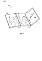
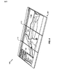
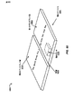
図1を参照すると、電子デバイスの第1の図示の実施形態が示され、全体的に100と称される。電子デバイス101は、第1のパネル102と、第2のパネル104と、第3のパネル106とを含む。第1のパネル102は、第1の折り畳み位置110において、第1のエッジに沿って第2のパネル104に結合される。第2のパネル104は、第2の折り畳み位置112において、第2のパネル104の第2のエッジに沿って第3のパネル106に結合される。パネル102、104、および106の各々は、液晶ディスプレイ(LCD)スクリーンなどの、視覚表示を与えるように構成されたディスプレイ面を含む。電子デバイス101は、複数のディスプレイ面を有し、ユーザが電子デバイス101の物理的構成を変更すると、ユーザインターフェースを自動的に調整するか、または画像を表示するように構成されたワイヤレス通信デバイスである。
With reference to FIG. 1, a first illustrated embodiment of an electronic device is shown and generally designated 100. The
図1に示されるように、第1のパネル102と第2のパネル104とは、様々なデバイス構成を可能にするために、第1の折り畳み位置110において回転可能に結合される。たとえば、第1のパネル102と第2のパネル104とは、ディスプレイ面が、実質的に平坦な表面を形成するためにほぼ同一平面(substantially coplanar)になるように配置され得る。別の例として、第1のパネル102と第2のパネル104とは、第1のパネル102の裏面が第2のパネル104の裏面と接触するまで、第1の折り畳み位置110の周りに互いに回転され得る。同様に、第2のパネル104は、第2の折り畳み位置112に沿って第3のパネル106に回転可能に結合され、第2のパネル104のディスプレイ面が第3のパネル106のディスプレイ面と接触する完全折り畳み閉構成、および第2のパネル104と第3のパネル106とがほぼ同一平面である完全展開形態を含む、様々な構成を可能にする。
As shown in FIG. 1, the
特定の一実施形態では、図2〜図7に関して後述されるように、第1のパネル102、第2のパネル104、および第3のパネル106は、1つまたは複数の物理的折り畳み状態に手作業で構成され得る。電子デバイス101が複数の折り畳み可能な構成に配置されることを可能にすることによって、電子デバイス101のユーザは、容易な操縦性および機能性のために小さいフォームファクタを有することを選択することができるか、またはリッチなコンテンツを表示するため、および拡張ユーザインターフェースを介して1つまたは複数のソフトウェアアプリケーションとのより多くの有意な対話を可能にするために、展開された、より大きいフォームファクタを選択することができる。
In one particular embodiment, as described below with respect to FIGS. 2-7, the
特定の一実施形態では、電子デバイス101は、複数の折り畳み式ディスプレイパネル102、104、および106を含む。完全に展開されると、電子デバイス101はワイドスクリーンテレビジョンと同様のパノラマビューを与えることができる。閉位置まで完全に折り畳まれると、電子デバイス101は小さいフォームファクタを与えることができ、さらにセルフォンと同様の省略ビューを与えることができる。一般に、複数の構成可能なディスプレイ102、104、および106は、電子デバイス101がどのように折り畳まれるか、または構成されるかに応じて、電子デバイス101が複数のタイプのデバイスとして使用されることを可能にし得る。
In one particular embodiment,
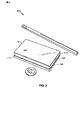
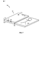
図2を参照すると、完全折り畳み形態における図1の電子デバイス101の第2の実施形態が示され、全体的に200と称される。第1のパネル102は、電子デバイス101の上面に示されている。図2に示されるように、第1のパネル102のディスプレイ面が見えており、第1のパネル102の裏面が第2のパネル104の裏面と接触しているように、第1のパネル102と第2のパネル104との間の第1の折り畳み位置110が完全に折り畳まれている。第3のパネル106は、第2の折り畳み位置112に沿って、第2のパネル104に対して完全に折り畳まれている。第2のパネル104は、第2のディスプレイ面が完全折り畳み形態の内側で実質的に第3のパネル106のディスプレイ面に近接するように構成される。図2に示されるように、電子デバイス101は、3段に重ねられた層(すなわち、第1のパネル102、第2のパネル104、および第3のパネル106)を含んでいる、実質的に矩形の形状またはフォームファクタを有する。第2のパネル104および第3のパネル106のディスプレイ面は、図2の完全折り畳み形態200の内側で外部ソースによる損傷から実質的に保護される。図2に示される実施形態は、サイズ比較目的のための米国25セント硬貨および鉛筆の隣にある、電子デバイス101の特定の実施形態を示すが、図2が、本出願のすべての他の図と同様に、必ずしも一定の縮尺でなく、本開示の範囲を制限するものと解釈されてはならないことは明確に理解されたい。
Referring to FIG. 2, a second embodiment of the
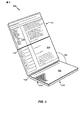
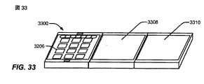
図3を参照すると、「サミング」構成における図1の電子デバイス101が示され、全体的に300と称される。第1のパネル102と第2のパネル104とは、ほぼ同一平面構成で第1の折り畳み位置110において結合される。第2のパネル104と第3のパネル106とは、第2の折り畳み位置112に沿って互いにオフセットされる。特定の一実施形態では、第3のパネル106のディスプレイ面から第2のパネル104のディスプレイ面までの回転の角度318は、90度よりも大きく、180度よりも小さい角度である。たとえば、図3に示されるように、第2のパネル104と第3のパネル106との間に形成される角度318は、実質的に135度であり得る。
Referring to FIG. 3, the
図3に示されるように、第1のパネル106の裏面314は、テーブル表面、机表面、ユーザの手などのサポート表面上で静止することができる。特定の一実施形態では、第3のパネル106は、図3に示される特定の構成において、電子デバイス101が、表面上でサミング構成300に維持されるときに安定であり得るように加重され得る。図示のように、サミング構成300では、ユーザは、実質的に水平のキーボード316と、第1のパネル102のディスプレイ面と第2のパネル104のディスプレイ面とで形成された、都合よく傾斜され、配置された有効な2パネルディスプレイ面とを有することができるように、第3のパネル106はキーボード316を表示することができ、第1のパネル102および第2のパネル104はグラフィカルユーザインターフェースの1つまたは複数の部分を表示することができる。特定の一実施形態では、キーボード316がユーザの片手または両手の親指によって作動され得るように、電子デバイス101はユーザによってサミング構成300に保持され得る。
As shown in FIG. 3, the
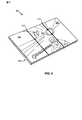
図4を参照すると、トラベルクロック構成における図1の電子デバイス101が示され、全体的に400と称される。第1のパネル102は、第2のパネル104に対して、第1の折り畳み位置110に沿って、180度よりも小さく、0度よりも大きい角度420で折り畳まれている。たとえば、第1のパネル102と第2のパネル104とによって形成される角度420は、実質的に60度であり得る。第2のパネル104は、第3のパネル106に対して、第2の折り畳み位置112に沿って、90度よりも大きく、180度よりも小さい角度422で向けられる。図示のように、第2の折り畳み位置112に沿った角度422は、約135度であり得る。
Referring to FIG. 4, the
特定の一実施形態では、トラベルクロック構成400は、第2のパネル104のディスプレイ面において、デジタル時計表示またはアナログ時計表示などのクロック表示418のディスプレイを含む。たとえば、クロック表示418は時計の文字盤の画像であり得る。特定の一実施形態では、第1のパネル102のディスプレイ面は電源切断構成であり得、第3のパネル106のディスプレイ面106は、アラームセットコントロール、ボリュームコントロール、無線局チューニングコントロール、または他のコントロール(図示されず)など、トラベルクロックによくある1つまたは複数のコントロールを表示することができる。
In one particular embodiment, travel clock configuration 400 includes a display of
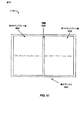
図5は、完全展開形態500における図1の電子デバイス101を示す。第1のパネル102と第2のパネル104とはほぼ同一平面であり、第2のパネル104は第3のパネル106とほぼ同一平面である。パネル102、104、および106は、第1のパネル102、第2のパネル104、および第3のパネル106のディスプレイ面が展開された3パネルディスプレイスクリーンを効果的に形成するように、第1の折り畳み位置110および第2の折り畳み位置112において接触し得る。図示のように、完全展開形態500では、ディスプレイ面の各々がより大きい画像の一部を表示しており、個々のディスプレイ面はより大きい画像の一部分を縦方向モードで表示し、より大きい画像は有効な3パネルスクリーンにわたって横方向モードで展開する。特定の一実施形態では、パネル102、104、および106は、実質的に完全展開形態500に維持されるようにロック可能であり得る。
FIG. 5 shows the
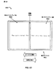
図6は、第1のパネル102、第2のパネル104、および第3のパネル106上の、図5に比較して縮小された有効ディスプレイ面を有する完全展開形態600における図1の電子デバイス101を示す。図5と同様に、パネル102、104、および106は、実質的に展開され、所定の位置にロックされ得る。しかしながら、図6に示されるように、パネル102、104、および106の各々の縦方向モードの上側および下側表面部分は、ディスプレイ面を含むことができず、代わりに、ヒンジ(hinge)、マイクロフォン、スピーカーまたは他のハードウェア機能(図示されず)など、1つまたは複数のハードウェア機能を含むことができる。
FIG. 6 illustrates the
図7は、ビデオ会議構成700における図1の電子デバイス101を示す。第1のパネル102は、第2のパネル104とほぼ同一平面になるように、第1の折り畳み位置110において第2のパネル104に結合される。第2のパネル104と第3のパネル106とは、第2のパネル104のディスプレイ面と第3のパネル106のディスプレイ面とが実質的に互いに近接し、折り畳み形態の内側で保護されるように、第2の折り畳み位置112に沿って折り畳み形態で結合される。第3のパネル106が第2のパネル104の上に折り畳まれることによって、カメラ720を含む第3のパネル106の裏面108が電子デバイス101のユーザに露出される。第3のパネル106の下部エッジは、マイクロフォン722とスピーカー724とを含む。第3のパネル106の下部エッジに示されているが、マイクロフォン722およびスピーカー724は、電子デバイス101上の他の位置に配置され得ることを明確に理解されたい。たとえば、図32に関して示されるように、マイクロフォン722は第1のパネル102のディスプレイ面の上部に配置され得、スピーカー724は第1のパネル102のディスプレイ面の下部位置に配置され得る。ビデオ会議構成700は、電子デバイス101のユーザが、第1のパネル102のディスプレイ面上でビデオ会議呼の参加者の画像を閲覧し、同時に、カメラ720の視界中に配置され、ユーザの画像をキャプチャし、ユーザのキャプチャされた画像をビデオ会議の1人または複数の参加者に与えることを可能にする。
FIG. 7 shows the
特定の一実施形態では、図1〜図7の電子デバイス101は、機械的に接続され、折り畳むことが可能であり、個々にまたは一緒に使用され得る3つの別々のタッチスクリーンディスプレイ102、104、および106を使用する。これは、電子デバイス101の形状または構成に基づいて変更され得る複数のユーザインターフェースを使用可能にする。複数の構成可能なユーザインターフェースは、電子デバイス101がどのように折り畳まれるか、またはどのように構成されるかに応じて、電子デバイス101が複数のタイプのデバイスとして使用されることを可能にする。電子デバイス101を使用するとき、ユーザは、単一のスクリーン(デバイスは完全に折り畳まれている)を用いて対話することによって開始することができ、次いで、電子デバイス101が異なる物理的構成に折り畳まれると、(アプリケーションまたは設定に基づいて)インターフェースを自動的に変化させる。電子デバイス101は、複数のスクリーン上で同時アプリケーションを実行し、デバイス構成を変更するユーザ対話に基づいてアプリケーションを再構成するように構成され得る。たとえば、電子デバイス101は、1つの物理的構成では、単一のディスプレイ102、104、または106においてアプリケーションを実行し、異なる物理的構成では、3つのディスプレイ102、104、および106のすべてにわたってアプリケーションを実行するように構成され得る。
In one particular embodiment, the
たとえば、電子デバイス101が閉位置まで完全に折り畳まれると(図2の完全折り畳み形態200など、1つのスクリーンが表示される)、電子デバイス101は、小さいフォームファクタを保持し、省略ユーザインターフェースビューを与えることができる。ユーザ対話に基づいて、この完全折り畳み形態は、電話、ショートメッセージサービス(SMS)、携帯情報端末(PDA)タイプのブラウザアプリケーション、キーパッド、メニュー、他のインターフェース要素、またはそれらの任意の組合せなど、アプリケーションを表示することができる。
For example, when the
完全に展開されると(図5の完全展開形態500または図6の600など、すべてのスクリーンが表示される)、電子デバイス101はパノラマビューを与えることができる。ユーザが選択したアプリケーションに基づいて、パノラマビューは、例示的で非限定的な例として、キーボードありまたはなしで、ワイドスクリーンビデオ、アプリケーション(たとえば、電子メール、テキストエディタ)をもつデスクトップ環境、またはウェブブラウザと同様のインターフェースを自動的に表示することができる。これらのインターフェースのための対話は、モバイルフォンタイプの対話に限定される代わりに、インターフェースのネイティブフォーマットと同様であり得る。
When fully deployed (all screens are displayed, such as fully deployed
ディスプレイが三角形状に折り畳まれると(図4のトラベルクロック構成400など、三角形の1つの部分は後向きのディスプレイであり、三角形の他の部分は前向きのディスプレイであり、最後の部分は下に折り畳まれるかまたは前方に平坦である)、この構成は指向性ユーザインターフェースの表示を自動的にトリガすることができる。言い換えれば、(1つまたは複数の)前面ディスプレイは、例示的で非限定的な例として、ゲームアプリケーション、電子メール、SMS、電話、アラームクロック、デジタル無線、または音楽プレーヤなど、特定の構成のためのデバイスインターフェースを示すことができ、同時に、後部ディスプレイ、下部ディスプレイ、または両方は、アイドルまたはオフであり得る。 When the display is folded into a triangle (such as travel clock configuration 400 in FIG. 4, one part of the triangle is a rear-facing display, the other part of the triangle is a forward-facing display, and the last part is folded down. This configuration can automatically trigger the display of the directional user interface. In other words, the front display (s) is for a specific configuration, such as a game application, email, SMS, phone, alarm clock, digital radio, or music player, as an illustrative non-limiting example The device display can be shown, while the rear display, the lower display, or both can be idle or off.
(図3のサミング構成300など)1つの外側ディスプレイが他のディスプレイに対して約45度の角度で構成されると、電子デバイス101はインターフェースを自動的に変更することができる。たとえば、インターフェースはテキスト入力デバイスであり得る。45度のディスプレイはキーボードを示すことができ、他のディスプレイは、テキスト入力アプリケーション、非PDAタイプのブラウザ、または他のデスクトップ様のアプリケーションを表示することができる。
When one outer display is configured at an angle of about 45 degrees relative to the other display (such as the summing
したがって、電子デバイス101は、機械的トリガ、センサ情報などに基づいてユーザインターフェースおよび対話方法を自動的に変更する能力を有することができる。電子デバイス101は、ユーザが複数のメニューをブラウズする必要なしに、デバイスに対するユーザの期待を予測するという利点を与えることができる。電子デバイス101は、完全に展開されると、現在のモバイルデバイスインターフェースよりも大きくなるので、スクリーンエリアが不十分である従来のモバイルデバイスの欠点を克服することができる。電子デバイス101のユーザは、使用時にユーザのニーズおよび好みによりぴったり一致するようにアプリケーションインターフェースを変更することができる。テキストエディタまたはブラウザのような、複雑なデスクトップ様のインターフェースを使用する従来のモバイルデバイスのユーザによって遭遇され得る困難は、インターフェースが複数のディスプレイにわたって広がることを可能にする電子デバイス101によって軽減され得る。
Thus, the
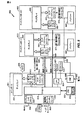
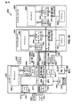
図8を参照すると、電子デバイスの特定の例示的な実施形態が示され、全体的に800と称される。デバイス800は、ヒンジ(図示されず)上の接続のセット890を介して第1のディスプレイボード803および第2のディスプレイボード805に結合されたメインボード801を含む。ボード801、803、および805の各々は、図1〜図7の電子デバイス101などのマルチパネルヒンジ結合デバイスの別々のパネル中に存在し得る。
With reference to FIG. 8, a particular exemplary embodiment of an electronic device is shown and generally designated 800.
メインボード801は、ディスプレイ802と、メモリ832に結合されたプロセッサ810と、ディスプレイコントローラ862と、タッチスクリーンコントローラ852と、ワイヤレスコントローラ840と、短距離ワイヤレスインターフェース846と、コーダ/デコーダ(コーデック)834と、電力管理集積回路(PMIC)880とを含む。第1のディスプレイボード803は、ディスプレイコントローラ864に結合されたディスプレイ804と、タッチスクリーンコントローラ854と、1つまたは複数の折り畳み形態/ティルトセンサ874とを含む。第2のディスプレイボード805は、ディスプレイコントローラ866に結合されたディスプレイ806と、タッチスクリーンコントローラ856と、1つまたは複数の折り畳み形態/ティルトセンサ876とを含む。第1のディスプレイボード803は、第1の高速シリアルリンク892などの第1の通信経路を介してメインボード801に結合される。第2のディスプレイボード805は、第2の高速シリアルリンク894などの第2の通信経路を介してメインボード801に結合される。第1のディスプレイボード803および第2のディスプレイボード805は、それぞれ電力線896を介してPMIC880に結合されたバッテリー884および886を有し、電力線896は、PMIC880とバッテリー884および886との間で少なくとも1.5アンペア(A)を伝導することが可能であり得る。特定の一実施形態では、カメラ820および電力入力882もメインボード801に結合される。
The
プロセッサ810は、1つまたは複数のARMタイプのプロセッサ、1つまたは複数のデジタル信号プロセッサ(DSP)、他のプロセッサ、またはそれらの任意の組合せなど、1つまたは複数の処理デバイスを含むことができる。プロセッサ810は、代表的なメモリ832など、1つまたは複数のコンピュータ可読媒体にアクセスすることができる。メモリ832は、データ(図示されず)およびソフトウェア833などのプロセッサ実行可能命令を記憶する。一般に、ソフトウェア833は、プロセッサ810によって実行可能であるプロセッサ実行可能命令を含み、アプリケーションソフトウェア、オペレーティングシステムソフトウェア、他のタイプのプログラム命令、またはそれらの任意の組合せを含むことができる。メモリ832はプロセッサ810の外部に示されているが、他の実施形態では、メモリ832は、キャッシュ、1つまたは複数のレジスタまたはレジスタファイル、プロセッサ810における他の記憶デバイス、またはそれらの任意の組合せなど、プロセッサ810の内部にあり得る。
The
プロセッサ810はまた、それぞれ、第1のディスプレイパネル803における折り畳み形態およびティルトセンサ874、ならびに第2のディスプレイパネル805における折り畳み形態およびティルトセンサ876などの折り畳み形態センサに結合される。例示的な例では、デバイス800は図1の電子デバイス101であり得、センサ874および876は、デバイス800の折り畳み形態を、図2に示される完全折り畳み形態、図3に示されるサミング構成、図4に示されるトラベルクロック構成、図5〜図6に示される完全展開形態、または図7に示されるビデオ会議構成のうちの1つまたは複数として検出するように適合され得る。
The
ディスプレイコントローラ862、864、および866は、ディスプレイ802、804、および806を制御するように構成される。特定の一実施形態では、ディスプレイ802、804、および806は、図1〜図7に示されたディスプレイ面102、104、および106に対応することができる。ディスプレイコントローラ862、864、および866は、プロセッサ810に応答して、デバイス800の構成に応じてディスプレイ802、804、および806に表示するグラフィカルデータを与えるように構成され得る。たとえば、デバイス800が完全折り畳み形態にあるとき、ディスプレイコントローラ862、864、および866は、第1のディスプレイ802を、グラフィカルユーザインターフェースを表示するように制御することができ、他のディスプレイ804および806を電源切断することまたは使用しないことが可能である。別の例として、デバイス800が完全展開形態にあるとき、ディスプレイコントローラ862、864、および866は、ディスプレイ802、804、および806を、3つのディスプレイ802、804、および806すべてにわたる単一の有効スクリーンとして動作するように、画像のそれぞれの部分をそれぞれ表示するように制御することができる。
特定の一実施形態では、ディスプレイ802、804、および806の各々は、それぞれ、タッチスクリーンコントローラ852、854、または856に結合されたそれぞれのタッチスクリーンを介してユーザ入力に応答する。タッチスクリーンコントローラ852、854、および856は、ディスプレイ802、804、および806からユーザ入力を表す信号を受信し、ユーザ入力を示すデータをプロセッサ810に与えるように構成される。たとえば、プロセッサ810は、第1のディスプレイ802上でアプリケーションアイコンのダブルタップを示すユーザ入力に応答することができ、ユーザ入力に応答してアプリケーションを起動し、ディスプレイ802、804、または806のうちの1つまたは複数にアプリケーションウィンドウを表示することができる。
In one particular embodiment, each of the
特定の一実施形態では、各ディスプレイコントローラ862、864、および866ならびに各タッチスクリーンコントローラ852、854、および856を、対応するディスプレイ802、804、および806とともに有することによって、コントローラと対応するディスプレイとを別々のパネル上に有する他の実施形態に比較して、パネル間で通信されるデータの量が低減され得る。しかしながら、他の実施形態では、ディスプレイコントローラ862、864、または866、あるいはタッチスクリーンコントローラ853、854、または856のうちの2つ以上は、3つのディスプレイ802、804、および806のすべてを制御する単一のコントローラなどに組み合わせられ得る。さらに、3つのディスプレイ802、804、および806が示されているが、他の実施形態では、デバイス800は3つよりも多いまたは少ないディスプレイを含み得る。
In one particular embodiment, having each
高速シリアルリンク892および894は高速双方向シリアルリンクであり得る。たとえば、リンク892および894はモバイルディスプレイデジタルインターフェース(MDDI)タイプのリンクであり得る。タッチスクリーンデータおよびセンサデータは、パネル801、803、および805間のそれぞれのヒンジ上のシグナリングのために4つの差動ペアのみが使用され得るように、パネル803および805からプロセッサ810に戻るようにシリアルストリーム中に埋め込まれ得る。
High speed
特定の一実施形態では、センサ874および876は、1つまたは複数のセンサにおいて受信される入力に基づいて、デバイス800の折り畳み形態を検出するように適合され得る。たとえば、センサ874および876のうちの1つまたは複数は、1つまたは複数の加速度計、インクリノメータ(inclinometer)、ヒンジ検出器、他の検出器、またはそれらの任意の組合せからの入力を含むかまたは受信することができる。センサ874および876は、デバイス800の検出された折り畳み形態を示す情報をプロセッサ810に与えることができる。センサ874および876は、デバイス800の隣接ディスプレイパネルに対するディスプレイパネルの回転の角度を検出することなどによって、相対的な折り畳み位置に応答することができる。センサ874および876はまた、デバイス800の1つまたは複数のディスプレイパネルに結合された1つまたは複数の加速度計またはインクリノメータなどの1つまたは複数の他のセンサに応答することができる。
In one particular embodiment, sensors 874 and 876 may be adapted to detect the folded configuration of
図8に示されるように、コーダ/デコーダ(コーデック)834もプロセッサ810に結合され得る。スピーカー822およびマイクロフォン824はコーデック834に結合され得る。図8はまた、ワイヤレスコントローラ840が、プロセッサ810およびワイヤレスアンテナ842に結合され得、デバイス800がワイドエリアネットワーク(WAN)などのワイヤレスネットワークを介して通信することを可能にすることができることを示す。デバイス800が着呼を受信すると、プロセッサ810はワイヤレスコントローラ840に応答して、ディスプレイ802、804、および806のうちの1つまたは複数に発呼者識別情報または発呼者番号などの呼表示を表示することができる。プロセッサ810は、センサ874および876からの入力に基づいて判断されたデバイス800の折り畳み形態に少なくとも部分的に基づいて呼表示を表示するために、サイズ、位置、および姿勢、ならびに特定のディスプレイ802、804、および806を判断することができる。たとえば、呼表示は、1つまたは複数の他のアプリケーション上に、折り畳み形態に基づくサイズ、配置、および姿勢を有するポップアップウィンドウまたはテキストとして表示され得る。
A coder / decoder (codec) 834 may also be coupled to the
特定の一実施形態では、デバイス800は、すべての折り畳み形態においてワイヤレス電話通信のために動作可能であるように構成される。特定の一実施形態では、プロセッサ810は、アンテナ848を介してヘッドセット850に結合され得る短距離ワイヤレスインターフェース846に結合される。短距離ワイヤレスインターフェース846は、ブルートゥースネットワークなどのアドホックワイヤレスネットワークを介して、イヤピースとマイクロフォンとを含むデバイスなどのヘッドセット850にワイヤレスに結合され得る。プロセッサ810は、着呼に応答して、呼表示を表示すべきか、またはヘッドセット850に警報を出すべきかを判断する論理を実装することができる。たとえば、デバイス800が完全展開形態にあり、マルチメディアファイルまたはストリーミングメディアがすべてのディスプレイ802、804、および806にわたって表示される場合、プロセッサ810は、ヘッドセット850に自動的に警報を出すことができ、他の場合は呼表示を表示することができる。
In one particular embodiment,
特定の一実施形態では、図8の1つまたは複数の構成要素は、デバイスパネルのうちの1つまたは複数に近接して、またはその内部に配置され得る。たとえば、プロセッサ810は中心パネル内に配置され得、外部パネルはそれぞれバッテリー884および886を格納することができる。特定の一実施形態では、パネルは、デバイスがサミング構成において立ったままであることを可能にするように加重され得る。
In one particular embodiment, one or more of the components of FIG. 8 may be located proximate to or within one or more of the device panels. For example, the
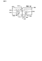
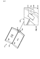
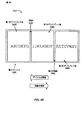
図9を参照すると、電子デバイスの特定の例示的な実施形態が示され、全体的に900と称される。デバイス900は、第1のパネル902と第2のパネル904とを含む。第1のパネル902と第2のパネル904とは、パネル902および904の上部エッジおよび下部エッジの近くの埋込みヒンジ905を介して結合される。特定の一実施形態では、電子デバイス900は、ユーザによって使用のための様々な構成に操作され得、構成変更に応答してソフトウェア構成または表示される画像を自動的に調整することができる。図示の実施形態では、電子デバイス900は、図1の電子デバイス101、図8の電子デバイス800、またはそれらの任意の組合せの2パネルの実施形態である。特定の一実施形態では、埋込みヒンジ905は結合部材906を含む。図9は、第1のパネル902および第2のパネル904の表面と実質的に面一であり、第1のパネルによって画成された第1のアパーチャ1040および第2のパネル904によって画成された第2のアパーチャ1044を通して見える結合部材906を示す、埋込みヒンジ905の拡大図を含む。
With reference to FIG. 9, a particular exemplary embodiment of an electronic device is shown and generally designated 900.
折り畳みディスプレイパネル902および904は、完全に展開されると、ワイドスクリーンテレビジョンと同様のパノラマビューを与えることができ、閉位置まで完全に折り畳まれると、小さいフォームファクタを与え、さらに従来のセルラー電話と同様の省略ビューを与えることができる。並進および回転を含むより複雑な動きを与える埋込みヒンジ905などの小さいヒンジは、ディスプレイパネル間隙を縮小し、より連続的なタイリングを作成するために使用され得、多数のディスプレイまたはパネルをもつ1つまたは複数の設計において使用され得る。
Folded
図10は、図9のデバイス900の側面部分断面図を示す。第1のパネル902は、第1のパネル902内で第1のキャビティ1042と通信している第1のアパーチャ1040を画成する。第2のパネル904は、第2のパネル904中の第2のキャビティ1046と通信している第2のアパーチャ1044を画成する。結合部材906は、第1のピン1010などの第1のピボット(pivot)部材、および第2のピン1008などの第2のピボット部材に結合される。第1のピン1010および第2のピン1008は、第1のパネル902が結合部材906に回転可能に結合されることを可能にし、第2のピン1008は、第2のパネル904が結合部材906に回転可能に結合されることを可能にする。結果として、第1のパネル902と第2のパネル904とは互いに回転可能に結合される。さらに、第1のパネル902中に画成されたアパーチャ1040および第2のパネル904中に画成されたアパーチャ1044は、それぞれ、結合部材906がその中に挿入されることを可能にするため、および結合部材906に対するパネル902および904の各々のある範囲の回転運動を可能にするために形成される。さらに、第1のピン1010は、第2のパネル904に対する第1のパネル902の横移動を可能にするために、埋込みヒンジ905が展開形態にあり、第1のピン1010がスロット1012の第1の端部にあるとき、第1のパネル902が第2のパネル904に対してある動き範囲を有するように第1のキャビティ1042内のスロット1012内に係合される。さらに、第1のパネル902は、埋込みヒンジ905が引込み形態にあり、第1のピン1010がスロット1012の第2の端部にあるとき、第2のパネル904に対して第2の動き範囲を有し、第1の動き範囲は第2の動き範囲よりも大きい。図15〜図20に関して論じられるように、センサは、第2のパネル904に対する第1のパネル902の相対姿勢を検出するために、埋込みヒンジ905に結合され得る。
FIG. 10 shows a side partial cross-sectional view of the
図示のように、第1のアパーチャ1040は、結合部材906の少なくとも第1の部分を受けるように寸法決定され、第1の部分は、ピン1010に結合された結合部材906の部分を含む。さらに、第2のアパーチャ1044は、結合部材906の少なくとも第2の部分を受けるように寸法決定され、第2の部分は、第2のピン1008に結合された部分を含む。さらに、第1のピン1010がスロット1012内の最内位置にあるとき、第1のキャビティ1042は、結合部材906を受けるために、展開された埋込み構成要素1014を含む。
As shown, the
図11は、傾斜構成1100における図9の電子デバイス900を示す。第1のパネル902は、結合部材906を含むものとして示される埋込みヒンジ905を介して、第2のパネル904に対してある角度で向けられる。図11は、図9に比較して、第2のパネル904の第2のアパーチャ1044の異なるエリアを通して展開する結合部材906を示す、埋込みヒンジ905の拡大図を含む。
FIG. 11 shows the
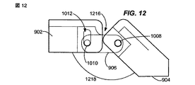
図12は、結合部材906を介して第2のパネル904に回転可能に結合された第1のパネル902を示す。結合部材906は、スロット1012中に係合された第1のピン1010を介して第1のパネル902に回転可能に結合され、第2のピン1008を介して第2のパネル904に回転可能に結合される。図12に示されるように、第2のパネル904は、第1のパネル902に対して当接され、アングルストップ1216を与える。図12の構成では、第2のパネル904は、パネル902の表面に対して平坦であるように完全に折り畳まれた位置まで内方向に回転され得、第1のパネル902に対する所定の角度1218まで外方向に回転され得、アングルストップ1216によってさらなる回転分離から防がれ得る。アングルストップ1216は、第2のパネル904を、図12の実施形態では第1のパネル902に対して実質的に135度として示される所定の角度1218に保持することができる。
FIG. 12 shows the
図13を参照すると、図9に示される電子デバイス900が完全折り畳み形態1300において示される。完全折り畳み形態1300は、スクリーンを含む、実質的に第2のパネル904に近接したディスプレイ面などの第1の面をもつ第1のパネル902を有する。埋込みヒンジ905は、第1のパネル902が完全折り畳み形態1300においてデバイス高さを縮小するために、実質的に第2のパネル904に近接して配置されることを可能にするように、引込み形態において示されている。埋込みヒンジ905の拡大図は、第1のパネル902の第1のアパーチャ1040および第2のパネル904の第2のアパーチャ1044を通って延びている結合部材906を示す図13中に示される。
Referring to FIG. 13, the
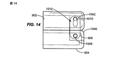
図14は、完全折り畳み形態1300の横部分断面図を示す。図14に示されるように、第1のパネル902は、第2のパネル904に対して完全に折り畳まれ、結合部材906は第1のパネル902の第1のキャビティ1042および第2のパネル904の第2のキャビティ1046の完全に内側にある。図示のように、結合部材906は、第2のピン1010がスロット1012の1つの末端において第1のキャビティ1042中に係合され、第1のパネル902と第2のパネル904とが実質的に互いに近接して配置され、図示のように、実質的に互いに対して平坦であることを可能にする。
FIG. 14 shows a cross-sectional side view of the fully folded
特定の一実施形態では、図15〜図17および図18〜図20に関してより詳細に論じられるように、多段折り(multi-fold)マルチフォールドモバイルデバイスがヒンジセンサからのフィードバックに基づいてディスプレイ画像の姿勢および内容を調整することができるように、埋込みヒンジ905はデテント式であり得、センサを備えることができる。ヒンジは、例示的で非限定的な例として、たとえば、位置を読み取るために、圧力センサ、電気接触、ホールセンサ、光学素子、または誘導検出を使用することができる。フィードバックは、2つ以上のヒンジ位置または回転から受信され得る。ヒンジは、折り畳みパネルが所定の位置にセットされることを可能にすることができ、マルチフォールドモバイルデバイスは、所定の位置にある折り畳みパネルを検出することに少なくとも部分的に基づいて、ディスプレイ画像の姿勢および内容またはユーザインターフェースを設定することができる。たとえば、ヒンジは、ボールデテント式(ball detented)であり得るか、完全開と完全閉との間の1つまたは複数の中間位置またはストップを有することができるか、ばね付勢され得るか、または折り畳みパネルが複数の位置において保持されることを可能にする他の構成を有することができる。たとえば、1つまたは複数のヒンジは、パネルが再配置のためにわずかに分離され、異なる構成にはね返ることを可能にされ得るようにばね付勢され得る。さらに、電子デバイスは、1つの折り畳みにおける第1のタイプのヒンジと、別の折り畳みにおける第2のタイプのヒンジとを有することができる。
In one particular embodiment, as will be discussed in more detail with respect to FIGS. 15-17 and 18-20, a multi-fold multifold mobile device may display images based on feedback from a hinge sensor. The embedded
たとえば、特定の一実施形態では、デテント式ヒンジは、パネルが平坦に、または一平面中に配置され、ディスプレイ画像がアクティブであり、横方向モードで閲覧可能な状態であることを可能にすることができる。マルチフォールドデバイスが平坦でないとき、左パネルは縦方向姿勢においてタッチパネルキーボードを含むことができ、他のディスプレイは縦方向モードで組み合わせられ得る。マルチフォールドデバイスが閉じているとき、右ディスプレイはアクティブで縦方向姿勢にあり、残りのディスプレイはオフおよび非アクティブのままであり得る。機能フローは、特定の位置にセットされたマルチフォールドデバイスと、位置を読み取る1つまたは複数のスマートヒンジと、位置を読み取ることに応答して調整する画像またはユーザインターフェースとを含むことができる。ディスプレイ画像またはユーザインターフェースのための多種多様な可能な構成がマルチフォールドデバイスにおいてデテント式ヒンジによって可能にされ得、特定の一実施形態では、小さいフォームファクタデバイスが、大画面マルチメディアデバイスとして使用されるように展開することを可能にされ得る。 For example, in one particular embodiment, the detent hinge allows the panel to be placed flat or in one plane and the display image is active and ready to be viewed in the landscape mode. Can do. When the multifold device is not flat, the left panel can include a touch panel keyboard in a vertical orientation, and other displays can be combined in a vertical mode. When the multifold device is closed, the right display may be active and in a vertical orientation, and the remaining displays may remain off and inactive. The functional flow can include a multi-fold device set at a particular position, one or more smart hinges that read the position, and an image or user interface that adjusts in response to reading the position. A wide variety of possible configurations for display images or user interfaces may be enabled by detent hinges in multifold devices, and in one particular embodiment, a small form factor device is used as a large screen multimedia device Can be enabled to be deployed.
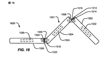
図15は、折り畳み形態1500における3パネル電子デバイスの特定の例示的な実施形態を示す。3パネルデバイス1501は、第1のパネル1502と、第2のパネル1504と、第3のパネル1506とを含む。第1のパネル1502は、破線で示される埋込みヒンジとして示される第1のヒンジ1505を介して第2のパネル1504に結合される。第2のパネル1504は第2のヒンジ1507を介して第3のパネル1506に結合される。第1のパネル1502は、1つまたは複数の電極、圧力センサ、他のセンサ、またはそれらの任意の組合せを含むことができ、様々な構成において第2のパネル1504の第1の端部1508に接触することができる第1のセンサ1512と、第2のセンサ1514と、第3のセンサ1516とを含む。さらに、第2のパネル1504は、様々な構成において、第3のパネル1506の第1のセンサ1522、第2のセンサ1524、および第3のセンサ1526、またはそれらの任意の組合せと接触することができる第2の端部1510を有する。第1のパネル1502は第1の内部センサ1532を含み、第2のパネル1504は第2の内部センサ1534を含み、第3のパネル1506は第3の内部センサ1536を含む。例示的な一実施形態では、3パネルデバイス1501は、図1〜図7の電子デバイス101、図8の電子デバイス800、図9〜図14の電子デバイス900の3パネル実施形態、またはそれらの任意の組合せであり得る。
FIG. 15 illustrates a particular exemplary embodiment of a three panel electronic device in a folded
特定の一実施形態では、3パネルデバイス1501は、センサ1512〜1516および1522〜1526におけるアクティビティに基づいて構成を認識することができる。特に、第2のパネル1504に対する第1のパネル1502の相対姿勢(relative orientation)は、第1のヒンジにおいて、第1のエッジ1508とセンサ1512〜1516のうちの1つまたは複数との間の接触の存在または不在などを介して検出され得る。さらに、第3のパネル1506との第2のパネル1504の相対姿勢は、第2のエッジ1510とセンサ1522〜1526のうちの1つまたは複数との間の接触の存在または不在を介して検出または感知され得る。図示のように、構成1500中の電子デバイス1501は完全折り畳み形態にある。同様に、センサ1532、1534、および1536のうちの1つまたは複数は、加速度計、傾きを測定するインクリノメータセンサ、ジャイロスコープセンサなどの、相対移動を測定するためのセンサ、別のタイプのセンサ、またはそれらの任意の組合せを含むことができる。これらのセンサ1512〜1516、および1522〜1526、ならびに内部センサ1532〜1536など、ヒンジにおけるセンサを使用することによって、折り畳み形態、相対または絶対整合、デバイスの傾きまたは他の物理的構成が、図8のプロセッサ810などのデバイスを制御するプロセッサを介して検出され得、応答され得る。
In one particular embodiment, the three
たとえば、センサ1512〜1516、および1522〜1526、ならびに内部センサ1532〜1536は、図8の折り畳み形態センサ826に含まれるかまたは供給され得る。デバイスは、ヒンジに結合されたセンサに応答して、少なくとも3つの所定の構成のセットからデバイス構成を検出する、図8のプロセッサ810などのプロセッサを含むことができる。センサは、ホールセンサ、光学センサ、または誘導センサのうちの少なくとも1つを含むことができる。ヒンジのうちの1つまたは複数は、第2のパネルに対する第1のパネルの安定展開形態(stable extended configuration)、折り畳み形態(folded configuration)、および中間構成(intermediate configuration)を可能にするためにデテント(detent)され得、プロセッサは、少なくとも3つの所定の構成に対応する少なくとも3つの所定の動作モードを有するソフトウェアアプリケーションを実行するように構成され得る。プロセッサはまた、検出されたデバイス構成に基づいてソフトウェアアプリケーションの動作モードを調整するように、ならびに検出されたデバイス構成に基づいて第1のディスプレイ面と第2のディスプレイ面と第3のディスプレイ面とに表示されるユーザインターフェースを調整するように適合され得る。たとえば、第1の所定の構成では、第1のディスプレイ面と第2のディスプレイ面と第3のディスプレイ面とが横方向構成において単一のスクリーンをエミュレートするように構成され得、第2の所定の構成では、第1のディスプレイ面がアクティブであり得、第2のディスプレイ面と第3のディスプレイ面とが非アクティブであり得、第3の所定の構成では、第3のディスプレイ面にキーボードが表示され得、第1のディスプレイ面と第2のディスプレイ面とが縦方向構成において単一のスクリーンをエミュレートするように構成され得る。センサ1532〜1536は内部センサとして示されているが、他の実施形態では、センサのうちの1つまたは複数は内部にある必要はなく、代わりにそれぞれのパネルの表面、またはパネルに対して他の位置において結合され得る。
For example, sensors 1512-1516 and 1522-1526, and internal sensors 1532-1536 may be included or supplied in the folded configuration sensor 826 of FIG. The device can include a processor, such as the
図16は、トラベルクロック構成1600における図15の電子デバイス1501を示す。第1のパネル1502は、センサ1512〜1516と第1の内部センサ1532とを含む。第1のセンサ1512および第2のセンサ1514は第2のパネル1504の第1の端部1508に接触せず、第3のセンサ1516は第1の端部1508に接触し、第2のパネル1502は、第2のパネル1504と実質的に90度の相対姿勢にある第1のアングルストップにおいて配置されることを示す。同様に、第2のパネル1504の第2のエッジ1510は、第3のパネル1506の第2のセンサ1524に接触しているが、第3のパネル1506の第1のセンサ1522または第3のセンサ1526には接触していない。したがって、デバイス1501のプロセッサは、第2のパネル1504が、図16に示されるように135度の相対的姿勢においてなど、第2のアングルストップにおいて第3のパネル1506と相対整合していると判断することができる。さらに、第2のパネル1504の内部センサ1534は、第2のパネル1504が重力方向引力に対して傾斜していることを示すことができ、第3のパネル1506の内部センサ1536は、第3のパネル1506が比較的水平な姿勢にあり、固定であることを示すことができ、したがって、電子デバイス1501は、電子デバイス1501がトラベルクロック構成1600に置かれていることを認識することができる。
FIG. 16 shows the
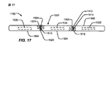
図17は、完全展開形態1700における図15の電子デバイス1501を示す。第1のパネル1502と第2のパネル1504とは、第2のパネル1504の第1の端部1508が第1のパネル1502の第1のセンサ1512および第3のセンサ1516には実質的に接触するが、第2のセンサ1514には接触しないように配置され、第1のパネル1502と第2のパネル1504とは、第3のアングルストップにおいてエンドツーエンド整合しており、約180度の相対的回転姿勢においてほぼ同一平面であることを示す。同様に、第2のパネル1504と第3のパネル1506とも、第2のエッジ1510が第3のパネル1506の第1のセンサ1522および第3のセンサ1526には接触するが、第2のセンサ1524には接触しないことにより検出され得るように、第3のアングルストップにおいてほぼ同一平面である。さらに、内部センサ1532、1534および1536のうちの1つまたは複数は、加速度、傾き、1つまたは複数の相対位置、またはそれらの任意の組合せを示すために使用され得る。パネル1502、1504、および1506の1つまたは複数のアングルストップまたは休止位置において、電子センサ、圧力センサ、磁界検出器、またはそれらの任意の組合せなどのセンサを含むことによって、電子デバイス1501はパネル1502〜1506のうちの1つまたは複数間の相対姿勢を判断することができ、電子デバイス1501がその現在のハードウェア構成を判断すること、ならびにセンサ1512〜1516および1522〜1526がそれぞれ係合および分離されたときにハードウェア構成の変化を検出することを可能にする。
FIG. 17 shows the
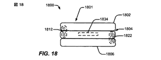
図18は、完全折り畳み形態1800における、第1のパネル1802と第2のパネル1804と第3のパネル1806とを有する電子デバイス1801を示す。第1のパネル1802は、第1のセンサ1812を含む埋込みヒンジを介して第2のパネル1804に回転可能に結合される。第2のパネル1804は、第2のセンサ1822を含む埋込みヒンジを介して第3のパネル1806に結合される。第2のパネル1804はまた、1つまたは複数の内部センサ1834を含む。特定の一実施形態では、埋込みヒンジ内の第1のセンサ1812は、第2のパネル1804に対する第1のパネル1802の相対的な配置が第1のセンサ1812において検出されることを可能にするために、第2のパネル1804への第1のパネル1802の回転整合、または結合部材に対するパネル1802および1804のうちの1つまたは複数間の回転度、ヒンジのピンのうちの1つまたは複数に対する回転度、重力方向に対する回転度、他の機構を介した回転度、またはそれらの任意の組合せを検出することができる。第2のセンサ1822は、第2のパネル1804と第3のパネル1806との間の相対姿勢を検出するために、第1のセンサ1812と実質的に同様に実行するように構成され得る。図15〜図17に示される実施形態の電子デバイス1501とは対照的に、完全折り畳み形態1800における図18の電子デバイス1801は単一の内部センサ1834と2つのヒンジセンサ1812および1822とを含み、電子デバイス1801が、内部センサ1834を使用して、姿勢、位置、運動量、または加速度など、第1のパラメータを検出すること、ならびにヒンジセンサ1812および1822を介して、パネル1802、1804、1806の折り畳み形態、展開形態、または部分折り畳み形態をさらに検出することを可能にする。特定の一実施形態では、電子デバイス1801は、図1〜図7の電子デバイス101、図8の電子デバイス800、図9〜図14の電子デバイス900の3パネル実施形態、図15〜図17の電子デバイス1501、またはそれらの任意の組合せであり得る。
FIG. 18 shows an
図19は、トラベルクロック構成1900における図18の電子デバイス1801を示す。第1のパネル1802は、第1のセンサ1812を含むヒンジを介して第2のパネル1804に約90度の角度で結合される。第2のパネル1804は、第2のセンサ1822を含むヒンジを介して第3のパネル1806に約135度の角度で結合される。内部センサ1834は、第1のセンサ1812および第2のセンサ1822におけるセンサの読みと組み合わせて、電子デバイス1801を制御するプロセッサに、電子デバイス1801がトラベルクロック構成1900にあることを示すことができる、第2のパネルの傾きを検出することができる。また、電子デバイス1801は、それぞれ第1のパネル1802と第2のパネル1804との間、および第2のパネル1804と第3のパネル1806との間で電子データおよび制御信号を通信するために1つまたは複数の信号経路1940および1942をも含む。特定の一実施形態では、信号経路1940および1942は、フレックスケーブル、1つまたは複数のワイヤ、光ファイバケーブルなどの他の信号担持媒体、信号を送信する他の導電性材料、またはそれらの任意の組合せを含むことができる。信号経路1940および1942を介して送信される信号は、直列、並列、または直列と並列との組合せにおいて送信され得、1つまたは複数のプロトコルに従って送信され得る。特定の一実施形態では、シグナリング経路1940および1942のうちの1つまたは複数はモバイルディスプレイデジタルインターフェース(MDDI)インターフェースを含むことができる。
FIG. 19 shows the
図20は、完全展開形態2000における図18の電子デバイス1801を示す。第1のパネル1802は第2のパネル1804とほぼ同一平面である。第2のパネル1804も第3のパネル1806とほぼ同一平面である。図示のように、第1のセンサ1812は、第1のヒンジが完全展開形態位置にあることを検出することができ、第2のセンサ1822は、第2のヒンジが完全展開形態位置にあることを検出することができる。さらに、内部センサ1834は、第2のパネル1804が実質的に平坦または水平な位置にあるかまたは整合していることを検出することができる。センサ1812、1822、および1834に基づいて、電子デバイス1801は、それが完全展開位置にあることを認識することができ、ソフトウェアまたはグラフィカルユーザインターフェースを、隣接するパネル1802〜1806の1つまたは複数のディスプレイ面上に横方向構成において表示するように構成することができる。
FIG. 20 shows the
図21を参照すると、電子デバイスの特定の実施形態が示され、全体的に2100と称される。特定の一実施形態では、電子デバイス2100は、図1〜図7の電子デバイス101、図8の電子デバイス800、図9〜図14の電子デバイス900、図15〜図17の電子デバイス1501、図18〜図20の電子デバイス1801、またはそれらの任意の組合せであり得る。
With reference to FIG. 21, a particular embodiment of an electronic device is shown and generally designated 2100. In one particular embodiment, the
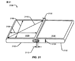
デバイス2100は、埋込みヒンジによって分離された、第1のパネル2122上の第1のディスプレイ面2120と、第2のパネル2132上の第2のディスプレイ面2130とを含む。各ディスプレイ面2120および2130は、縦方向高さ2106と、縦方向幅2108と、対角寸法2110とを有する。ディスプレイ面2120および2130は、ほぼパネル2122および2132の各々のエッジまで展開する。間隙2102は、第1のディスプレイ面2120のエッジと第2のディスプレイ面2130のエッジとの間の距離を示す。パネル2122および2132は高さ寸法2104を有する。電子デバイス2100は、ヒンジ移動距離2112として示される、ピンの直線動き範囲を可能にするスロットをもつ埋込みヒンジを含む。特定の一実施形態では、間隙2102は、ディスプレイ面2120および2130の寸法に対して小さくなるように設計される。さらに、高さ寸法2104は、完全折り畳み形態において好都合なサイズになるために、ディスプレイ面に対して小さくなるように設計される。さらに、ヒンジ移動距離2112は、パネル2120および2130が完全展開位置から完全折り畳み位置まで回転し、再構成後に実質的にロックされる位置に埋め込まれるように展開することを可能にするように調整され得る。例示的な一実施形態では、ヒンジ移動距離2112は2ミリメートル(mm)〜10mmの間であり得る。たとえば、ヒンジ移動距離2112は約5mmであり得る。
特定の一実施形態では、縦方向高さ2106は5〜10センチメートル(cm)の間であり得、縦方向幅2108は4〜8cmの間であり得、対角寸法2110は6〜13cmの間であり得、完全に折り畳まれるとズボンまたはジャケットのポケットにフィットする好都合なサイズを可能にすると同時に、タッチスクリーンインターフェースを介してユーザの指によって個々に選択されるのに十分なサイズおよび間隔の複数のアイコンまたはコントロールを与えるのに十分大きいディスプレイエリアを与える。例示的な一実施形態では、縦方向高さ2106は約8cmであり得、縦方向幅2108は約6cmであり得、対角寸法2110は約10.2cm(すなわち、約4インチ)であり得る。
In one particular embodiment, the
特定の一実施形態では、間隙2102は約0〜2.4mmの間である。例示的な一実施形態では、間隙2102は2mm未満であり、第1のディスプレイ面2120のエッジを越えて第2のパネル2132のほうへ展開する第1のパネル2122の部分と、第2のディスプレイ面2130のエッジを越えて第1のパネル2122のほうへ展開する第2のパネル2132の部分とから、実質的に一様に形成され得る。特定の一実施形態では、間隙2102は、画像またはビデオがディスプレイ面2120および2130上に表示されるとき、人間の視覚系が、間隙2102に対応する消失した部分を直ちにまたは最終的に無視することができるように、またはその部分によって実質的に気を散らされ得ないように寸法決定される。
In one particular embodiment, the
特定の一実施形態では、高さ寸法2104は、ディスプレイパネル2120および2130、内部電子回路、1つまたは複数のバッテリー、センサ、またはそれらの任意の組合せの厚さを含むのに十分大きいが、デバイス2100が完全折り畳み形態にあるとき、ズボンのポケットに好都合に入れられるのに十分小さい。たとえば、3つのパネルを有する一実施形態では、3パネル完全折り畳み形態におけるデバイスの高さが16.5mm以下であるように、高さ寸法2104は5.5mm未満であり得る。例示的な一実施形態では、高さ寸法2104は約5mmである。
In one particular embodiment, the
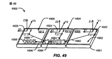
図22は、5つの構成可能なパネルを有する電子デバイス2201の特定の例示的な実施形態を示す。電子デバイス2201は、完全展開形態2200における第1のパネル2202と第2のパネル2204と第3のパネル2206と第4のパネル2208と第5のパネル2210とを有する。特定の一実施形態では、パネル2202〜2210の各々は、完全展開形態2200において、有効スクリーンエリアがパネル2202〜2210のすべてのディスプレイ面によって形成され得るように、それぞれのディスプレイ面2222、2224、2226、2228、および2230を含むことができる。特定の一実施形態では、電子デバイス2201は、図1〜図7の電子デバイス101、図8の電子デバイス800、図9〜図14の電子デバイス900、図15〜図17の電子デバイス1501、図18〜図20の電子デバイス1801、図21の電子デバイス2100、またはそれらの任意の組合せの5パネル実施形態であり得る。
FIG. 22 illustrates a particular exemplary embodiment of an
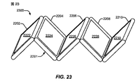
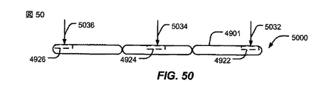
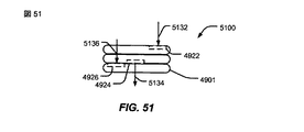
図23は、遷移構成2300における図22の電子デバイス2201の特定の実施形態を示す。第1のパネル2202は、第1のパネル2202と第2のパネル2204とが、図22に示される完全展開位置から、各パネル2202および2204の裏面が他のパネルの裏面に近接する位置まで回転することを可能にするように、第2のパネル2204に結合される。同様に、第2のパネル2204と第3のパネル2206とは、少なくとも完全展開位置から、パネル2204のディスプレイ面2224がパネル2206のディスプレイ面2226に近接する完全折り畳み位置まで配置可能であるように、回転可能に結合される。パネル2206とパネル2208とは、少なくとも完全展開位置から、パネル2206の裏面がパネル2208の裏面に近接する完全折り畳み位置まで配置されるように、回転可能に結合される。パネル2208とパネル2210とは、少なくとも完全展開位置から、パネル2208のディスプレイ面2228がパネル2210のディスプレイ面2230に近接する完全折り畳み位置まで配置可能であるように、回転可能に結合される。特定の一実施形態では、図22および図23に示される電子デバイス2201は、図1〜図21に示される電子デバイス101、800、900、1501、1801、または2100に概して類似であり得、前に開示された実施形態の1つまたは複数の構成、動作、センサ、ヒンジ、あるいは他の機能を含むことができる。折り畳み形態の変化に基づいてグラフィカルディスプレイを自動的に調整し、本開示の範囲内であるポータブル電子デバイス中に、任意の数のパネルが含まれ得ることを理解されたい。
FIG. 23 illustrates a specific embodiment of
図24は、分離構成2400における、3つの着脱可能なパネルを有する電子デバイス2401の特定の例示的な実施形態を示す。第1のパネル2402は、第1のパネル2402が第2のパネル2404の第2の結合機構2412を介して第2のパネル2404に結合することを可能にする結合機構2410を含む。結合機構2410および2412は、第1のパネル2402と第2のパネル2404との間の機械的および電子的結合を行うように構成され得る。同様に、第2のパネル2404は、第3のパネル2406の第4の結合機構2416への機械的および電子的結合を行うように構成された第3の結合機構2414を含む。特定の一実施形態では、電子デバイス2401は、図1〜図7の電子デバイス101、図8の電子デバイス800、図9〜図14の電子デバイス900、図15〜図17の電子デバイス1501、図18〜図20の電子デバイス1801、図21の電子デバイス2100、図22〜図23の電子デバイス2201、またはそれらの任意の組合せの着脱可能パネル実施形態であり得る。
FIG. 24 illustrates a particular exemplary embodiment of an
図25は、完全結合構成2500における図24の電子デバイス2401を示す。第1のパネル2402は第2のパネル2404に固定式に結合され、第2のパネル2404は第3のパネル2406に固定式に結合される。パネル2402〜2406は完全展開形態にある。特定の一実施形態では、図24に示される結合機構2410〜2416は、パネル2402〜2406間で回転運動がほとんど可能にされないように、パネル2402、2404、2406をしっかりと結合することができる。ただし、他の実施形態では、結合機構2410〜2416は、図1〜図23に関して説明される機能を可能にするために、パネル2402〜2406のうちの1つまたは複数の、互いに対する回転運動を与えるかまたは可能にすることができる。
FIG. 25 shows the
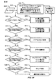
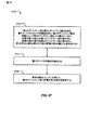
図26は、全体的に2600と称される、マルチパネル電子デバイスにおいてソフトウェア状態を変更する方法の例示的な実施形態のフローチャートである。特定の一実施形態では、方法2600は、図1〜図7の電子デバイス101、図8の電子デバイス800、図9〜図14の電子デバイス900、図15〜図17の電子デバイス1501、図18〜図20の電子デバイス1801、図21の電子デバイス2100、図22〜図23の電子デバイス2201、図24および図25の電子デバイス2401、またはそれらの任意の組合せにおいて実行され得る。
FIG. 26 is a flowchart of an exemplary embodiment of a method for changing software state in a multi-panel electronic device, generally designated 2600. In one particular embodiment,
特定の一実施形態では、電子デバイスは、折り畳みモード、完全展開モード、サミングモード、ビデオ会議モード、およびトラベルクロックモードを含む明確なハードウェア構成を含むことができる。各パネルまたはパネル間の折り畳み中のセンサは、パネルまたはヒンジ位置の変化を検出し、報告することができる。パネルまたはヒンジ位置は、約−180度〜約180度の間の範囲内などの折り畳み度で報告され得る。図18〜図20に示される内部センサ1834など、中間パネル中の1つまたは複数のセンサは、姿勢変化を検出し、報告することができる。ソフトウェアコントローラは、センサ入力を収集し、分析することができ、センサ入力に応答して1つまたは複数のアクションをとることを決定することができる。たとえば、ソフトウェアコントローラは、アプリケーションウィンドウまたはユーザインターフェース要素など、アプリケーションのサイズの変更を開始し、アプリケーションの姿勢の変更を開始し、アプリケーションの自動起動を開始し、アプリケーションの自動終了を開始し、アプリケーションの状態変更を開始し、またはアクションの組合せを行うことができる。
In one particular embodiment, the electronic device can include well-defined hardware configurations including a folding mode, a fully expanded mode, a summing mode, a video conferencing mode, and a travel clock mode. Sensors during folding between each panel or panels can detect and report changes in panel or hinge positions. The panel or hinge position may be reported with a degree of folding, such as within a range between about -180 degrees to about 180 degrees. One or more sensors in the intermediate panel, such as the
図26に示されるように、電子デバイスは、2602において定義されたソフトウェア状態を有する。たとえば、定義されたソフトウェア状態は、アプリケーションが動作中であるか待機中であるか、アプリケーションがキーボード入力などのユーザ入力を受信するかどうか、1つまたは複数のアプリケーションウィンドウサイズ、位置、姿勢、およびアプリケーションに与えられたユーザインターフェースのタイプなど、1つまたは複数のパラメータを示すことができる。定義されたソフトウェア状態2602は、アプリケーションにとって利用可能なパネルの数およびディスプレイモードを示すことができる。たとえば、デバイスは折り畳み形態にあり得、ソフトウェアコントローラは1パネル縦方向モードでアプリケーションを起動していることがあり得る。アプリケーションは、利用可能なパネルの数およびディスプレイモードに応答して、ユーザエクスペリエンスを改善するために、1つまたは複数の所定の状態を定義するかまたは含むことができる。
As shown in FIG. 26, the electronic device has a software state defined at 2602. For example, the defined software state may include one or more application window sizes, position, orientation, and whether the application is running or waiting, whether the application receives user input such as keyboard input, and so on. One or more parameters can be indicated, such as the type of user interface provided to the application. The defined
センサ入力2604が受信され、2606においてパネル位置が分析される。特定の一実施形態では、センサ入力2604は、ヒンジ位置、姿勢、または移動のうちの1つまたは複数の変化を示すことができる。たとえば、ヒンジ位置の変化は、図15〜図17のセンサ1512〜1516または図18〜図20のセンサ1812および1822などのヒンジセンサによって検出され得、姿勢または移動の変化は、図15〜図17の内部センサ1532〜1536または図18〜図20の内部センサ1834などの1つまたは複数の内部センサによって検出され得る。さらに、ヒンジ位置の変化は、隣接するパネルに結合されたインクリノメータによって検出される、隣接するパネルの相対姿勢の変化などを介して、ヒンジセンサ以外のセンサによって間接的に検出され得る。
A
判断2608に移動すると、電子デバイスが、定義されたハードウェア状態にあるかどうかの判断が行われる。電子デバイスが定義されたハードウェア状態にない場合、処理は2602に戻る。たとえば、判断されたハードウェア構成があらかじめ定義されたハードウェア構成の1つでない場合、ソフトウェアコントローラは、デバイスが既知の状態への遷移中であると仮定し得、追加のセンサ入力を待機し得る。
Moving to
2608において、電子デバイスが定義されたハードウェア状態にあると判断された場合、2610において、電子デバイスは新しいソフトウェア状態に入る。たとえば、電子デバイスが完全展開ハードウェア構成にあると判断された場合、ソフトウェアコントローラは、3パネル横方向モードまたは3パネル縦方向モードなどの新しいレイアウト要件を用いて、アプリケーションを再構成することができる。 If it is determined at 2608 that the electronic device is in a defined hardware state, at 2610 the electronic device enters a new software state. For example, if it is determined that the electronic device is in a fully deployed hardware configuration, the software controller can reconfigure the application with new layout requirements such as a three panel horizontal mode or a three panel vertical mode. .
特定の一実施形態では、ソフトウェアコントローラは、回路または他のハードウェア、ファームウェア、図8のプロセッサ810、汎用プロセッサまたは専用プロセッサなど、プログラム命令を実行する1つまたは複数のプロセッサ、またはそれらの任意の組合せによって実装され得る。特定の一実施形態では、図8のソフトウェア834などのアプリケーションは、複数のあらかじめ定義された動作状態をサポートするために書き込まれ得、特定のハードウェア状態または状態の変化を示す割込みまたはセマフォなどの制御信号に応答し得る。特定の一実施形態では、ソフトウェアは、ハードウェア構成に照会すること、およびソフトウェア状態を自己調整することを担当する。別の実施形態では、ソフトウェアは、ソフトウェアコントローラからハードウェア状態変化メッセージを受信するインターフェースをサポートすることを担当する。
In one particular embodiment, the software controller is a circuit or other hardware, firmware, one or more processors that execute program instructions, such as
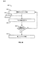
図27〜図31は、電子デバイス2701の検出されたハードウェア構成に応答して、キーボードを自動的に構成することの特定の実施形態を示す。特定の一実施形態では、電子デバイス2701は、図1〜図7の電子デバイス101、図8の電子デバイス800、図9〜図14の電子デバイス900の3パネルバージョン、図15〜図17の電子デバイス1501、図18〜図20の電子デバイス1801、図21の電子デバイス2100、図22〜図23の電子デバイス2201、図24および図25の電子デバイス2401、またはそれらの任意の組合せであり得る。特定の一実施形態では、電子デバイス2701は、図26の方法2600に従って動作するように構成される。
FIGS. 27-31 illustrate a specific embodiment of automatically configuring the keyboard in response to the detected hardware configuration of the
図27は、完全折り畳み形態2700における電子デバイス2701を示す。完全折り畳み形態2700における電子デバイス2701は、単一のパネルディスプレイ面が露出しており、ディスプレイウィンドウ2704およびキーボードエリア2702を示す。特定の一実施形態では、キーボードエリア2702は、またディスプレイウィンドウを含むディスプレイ面の一部として表示される画像であり、タッチスクリーン表面において検出されるキー押下によって作動され得る。図示のように、ディスプレイウィンドウ2704とキーボードエリア2702とを含む画像は、単一の露出されたディスプレイ面上に縦方向姿勢において表示される。別の実施形態では、電子デバイス2701は、ディスプレイウィンドウとキーボードエリアとを含む画像を横方向姿勢において表示するように構成され得る。電子デバイス2701は、1つまたは複数のセンサに応答して、電子デバイス2701の検出された姿勢に基づいて、縦方向姿勢または横方向姿勢において選択的にキーボードエリアを表示することができる。
FIG. 27 shows an
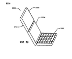
図28は、サミング構成2800における図27の電子デバイス2701を示す。サミング構成2800では、下部パネルは、図27に示される、より小さいキーボードエリア2702よりも大きいキーボードエリア2802を表示するディスプレイ面を有する。中間パネルの第1のディスプレイ面2804と上部パネルの第2のディスプレイ面2806とは、2つの別々のディスプレイウィンドウを形成することができるか、または2パネル有効スクリーンを形成するように組み合わせられ得る。図27のキーボードエリア2702よりも大きいキーボードエリア2802は、より容易な使用を可能にし、キーボードエリア2802を示しているディスプレイ面において、タッチスクリーンを介して有効データ入力を移動することができる。
FIG. 28 shows the
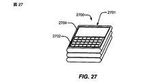
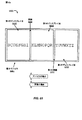
図29は、完全展開形態2900における図27の電子デバイス2701を示す。完全展開形態2900では、キーボードは、3つのパネルすべてにわたって展開され、3パネル幅および1パネル高さの有効ディスプレイスクリーンを形成するように示されている。有効スクリーンを備えるパネルの各々が、表示される横方向画像のそれぞれの部分を縦方向構成において表示するが、横方向モードにおける有効ディスプレイスクリーンは高さよりも広い。キーボードの右端部分2902は、右端パネルのディスプレイエリアの右端部分2908の下に表示される。中心パネルは、ディスプレイエリアの中心部分2910の下にキーボードの中心部分2904を表示する。左端パネルは、ディスプレイエリアの左端部分2912の下にキーボードの左端部分2906を表示する。
FIG. 29 shows the
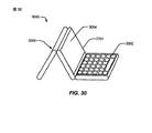
図30は、トラベルクロック構成3000における図27の電子デバイス2701を示す。第1の水平パネルは、タッチスクリーン表面によって認識されるタッチを介して作動され得るキーボードエリア3002を表示する。中心パネルの第2のディスプレイ面3004は、アプリケーションウィンドウ、アイコン、他のコントロール、ならびにクロック表示の視覚表示のために使用され得る。第3のディスプレイ面3006は、電源切断されたディスプレイエリア、あるいは、常夜灯、1つまたは複数の装飾用デザインを表示すること、ユーザが指定した表示、またはそれらの任意の組合せなど、他の機能を実行するディスプレイエリアを有することができる。
FIG. 30 shows the
図31は、ビデオ会議構成3100における図27のデバイス2701を示す。カメラ3104は、折り畳み形態において示される左端パネルの裏面上に示される。左端パネルの裏面は、追加のディスプレイ3102などの追加のユーザインターフェース機構を含むことができる。さらに、右端パネルは、ディスプレイ面の下部におけるキーボードエリア3106と、キーボードエリア3106の上方に配置され、ビデオ会議呼において参加者の画像を示すことができるディスプレイエリア3108とを与えるように分割され得る。一般に、図27〜図31に示されるように、電子デバイス2701は、パネルの内部、ヒンジの内部の1つまたは複数のセンサ、または他のセンサなどを介して、デバイス2701の形態を認識するようにプログラム可能であり得、1つまたは複数の適切なディスプレイ面の適切な部分においてキーボードの表示を自動的に再構成することができる。ディスプレイパネル、および特にキーボードの再構成、再表示、および再姿勢設定は、ユーザ構成、折り畳み、ハードウェア調整、傾き、姿勢、加速度、またはそれらの任意の組合せに応答して、ユーザのさらなる入力が必要とされるかまたは検出されることなしに自動的に実行され得る。
FIG. 31 shows the
図32〜図37は、電子デバイス3201の構成に応答し、アプリケーションを開くおよび閉じるユーザ入力にさらに応答するアイコンコントロールパネルを有する電子デバイス3201を示す。特定の一実施形態では、電子デバイス3201は、図1〜図7の電子デバイス101、図8の電子デバイス800、図9〜図14の電子デバイス900の3パネルバージョン、図15〜図17の電子デバイス1501、図18〜図20の電子デバイス1801、図21の電子デバイス2100、図22〜図23の電子デバイス2201、図24および図25の電子デバイス2401、図27〜図31の電子デバイス2701、またはそれらの任意の組合せであり得る。特定の一実施形態では、電子デバイス3201は、図26の方法2600に従って動作するように構成される。
FIGS. 32-37 illustrate an
図32は、完全折り畳み形態3200における電子デバイス3201を示す。左端パネルのディスプレイ面は、1つまたは複数のコントロール、または、たとえば、電力インジケータ、信号強度インジケータ、アラーム信号、デジタルネットワーク帯域幅指示、表示、またはそれらの任意の組合せを含むワイヤレス電話表示など、他の表示3204を示す。上側ディスプレイ面は、代表的なアプリケーションアイコン3206などの複数のアプリケーションアイコンをさらに含む。アプリケーションアイコンは、ディスプレイ面においてタッチセンシティブ表面を介してユーザ入力に応答することができる。電子デバイス3201は、電話通信のために使用可能であり得、マイクロフォン3240、スピーカー3242、電子デバイス3201の1つまたは複数の機能を可能にする他のハードウェア要素、またはそれらの任意の組合せを含むことができる。
FIG. 32 shows the
図33は、完全展開形態3300における図32の電子デバイス3201を示す。デバイス3201が図32の完全折り畳み形態3200から図33の完全展開形態3300まで展開されると、中心パネルのディスプレイスクリーン3308および右端パネルのディスプレイスクリーン3310が露出され、ユーザによって閲覧可能である。ディスプレイスクリーン3308および3310はデスクトップ領域を示すことができ、左端パネルは代表的なアプリケーションアイコン3206を含むアイコンパネルを示し続けることができる。
FIG. 33 shows the
図34は、ユーザ入力に応答する、左端ディスプレイ面と中心ディスプレイ面3308との間の間隙3414のほうへの代表的なアプリケーションアイコン3206の移動を示す。たとえば、ユーザ入力は、間隙3414のほうへの代表的なアプリケーションアイコン3206の移動を示すドラッグ動作であり得、アプリケーションアイコン3206の移動の速度および方向によって、代表的なアプリケーションアイコン3206が間隙3414を越えて移動されるべきであることを示すことができる。代表的なアプリケーションアイコン3206の移動は、矢印3412として示され、移動の速度は矢印3412の長さとして示され、移動の方向は矢印3412の方向として示される。ユーザ入力がタッチスクリーンにおけるドラッグ動作として受信されるように、アプリケーションアイコン3206の移動の速度および方向は、ユーザ入力に関連付けられたユーザの意図の予測を行うために使用され得る。たとえば、ユーザ入力が間隙3206に達する前に終了した場合でも、アプリケーションアイコン3206の移動の速度および方向は、ユーザ入力が間隙3414を越えてアプリケーションアイコン3206を移動するように意図されることを予測するために使用され得る。特定の一実施形態では、ユーザがユーザインターフェース要素の動きを開始することができ、ユーザインターフェース要素がインターフェースのシミュレートされた物理的特性に従ってその動きを続けることができるように、運動量および摩擦など、ユーザインターフェース要素に対して1つまたは複数の物理法則がシミュレートされ得る。たとえば、ドラッグ動作によって動かされ、リリースされたインターフェース要素は、ユーザにとって予測可能であり、ユーザによって自然または直観的であると知覚され得るような方法で、減速し、停止することができる。
FIG. 34 illustrates the movement of the
図34に示されるように、ユーザ入力によって与えられた移動の速度および方向は、アイコン3206が間隙3414を越えるための命令を示すので、アイコン3206の少なくとも一部分は中心ディスプレイパネル3308に表示され得、アイコン3206の残りの部分は左端ディスプレイパネルに表示され得る。このようにして、ユーザは、間隙3414を越えて連続的動きを有する代表的なアプリケーションアイコン3206の視覚的基準を維持することができる。特定の一実施形態では、図示されるように、アイコン3206が比較的緩やかに移動されると、代表的なアプリケーションアイコン3206は、間隙3414を越えて移動され得、中心ディスプレイエリア3308中に配置され得る。しかしながら、アプリケーションアイコン3206が間隙3414を越えて十分な速度で移動されると、電子デバイス3201は、間隙3414を越える代表的なアプリケーションアイコン3206の移動を示すユーザ入力を、代表的なアプリケーションアイコン3206に関連付けられたアプリケーションの起動命令と解釈することができる。
As shown in FIG. 34, the speed and direction of movement provided by the user input indicates a command for the
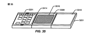
図35に示されるように、特定の一実施形態では、図32〜図34のアプリケーションアイコン3206が十分な速度で間隙3414を越えて引っ張られると、中心ディスプレイエリア3308においてアプリケーションウィンドウ3516を開くことなどによって、アプリケーションアイコン3206に関連付けられたアプリケーションが起動される。別の実施形態では、アプリケーションウィンドウ3516は中心ディスプレイ面3308および右端ディスプレイ面3310にわたるように展開することができ、2パネル有効ディスプレイスクリーンとして動作するように構成され得る。
As shown in FIG. 35, in one particular embodiment, if the
図36に示されるように、特定の一実施形態では、ユーザは、アプリケーションウィンドウ3516に対して、矢印3618によって示される、間隙3414のほうへの移動を有するように指示するユーザ入力を与えることによって、アプリケーションウィンドウ3516を閉じるように電子デバイスに命令することができる。アプリケーションウィンドウ3516は、間隙3414のほうへ進行するように表示され得、また、電子デバイス3201のユーザに、アプリケーションウィンドウ3516が少なくとも部分的に間隙3414を越えているかのように見える視覚的連続性を与えるために、少なくとも一部分が左端パネルの第1のディスプレイ面に表示されるように表示され得る。特定の一実施形態では、間隙3414を越える、アプリケーションウィンドウ3516の特定の動きが生じたとき、またはこれから生じるときなど、アプリケーションウィンドウ3516がユーザ入力によって間隙3414のほうへ十分な距離だけ移動するように命令されたとき、電子デバイス3201は、アプリケーションウィンドウ3516に表示されたアプリケーションを閉じるコマンドとしてユーザ入力を解釈し、アプリケーションおよびアプリケーションウィンドウ3516を閉じ、図37に示されるように左端表面パネル中のその元の位置に代表的なアプリケーションアイコン3206を戻すことができる。
As shown in FIG. 36, in one particular embodiment, the user provides user input to instruct the
図32〜図37は、イベントまたはユーザインターフェースとの対話をトリガするために、マルチスクリーン電子デバイス上のタッチスクリーン間の間隙を使用する対話の方法を示す。間隙の配置およびサイズを知ることによって、アプリケーションまたはソフトウェアは、別の対話の方法として間隙を使用することができる。一例として、ブラウザは、1つのスクリーンから、残りのスクリーン上に表示するように起動され得る。第1のスクリーンは、図33のアプリケーションアイコン3206など、ブラウザのアイコンを含むアプリケーションアイコンを含むことができる。ユーザは、ブラウザのアイコン上に自分の指を置き、次いで図34の間隙3414などのスクリーン間隙の方向にアイコンをドラッグすることができる。ユーザが間隙に達すると、対話が開始され、視覚化され、残りのスクリーン中に開いているブラウザを示すことができる。このトリガの逆の使用は、閉じる機能または非表示にする機能を開始して開始スクリーンに戻す、図35のアプリケーションウィンドウ3516など、開いているアプリケーションのある一部を所与の間隙を越えてドラッグすることを含むことができる。
FIGS. 32-37 illustrate a method of interaction using a gap between touch screens on a multi-screen electronic device to trigger an event or interaction with a user interface. Knowing the placement and size of the gap allows the application or software to use the gap as another way of interaction. As an example, a browser can be launched from one screen to display on the remaining screens. The first screen may include application icons including browser icons, such as
図34および図36に示されるように、ユーザが複数のスクリーン上にドラッグしている間、間隙を越えた方向および配置を両方とも示すために、ユーザインターフェース要素の順方向側で視覚キューが使用され得る。ドラッグされると、アイコンまたはアプリケーションウィンドウなどのユーザインターフェース要素は、順方向にいくつかのピクセルだけシフトすることができるので、ユーザインターフェース要素は依然としてユーザに可視であり、方向をキューイングする。アプリケーションを自動起動するか、またはユーザインターフェース要素を別のスクリーンに移動するなどのために、複数のスクリーン間の間隙を越えてドラッグすると、ユーザインターフェース要素は、スクリーンを越えて移動する方向および能力を両方とも示すために、測定された間隙と同じ距離だけ順方向にシフトすることができる。方向、配置、および間隙を越える能力を示すことによって、電子デバイス3201は、ユーザインターフェース要素をドラッグする間、ユーザに連続キューを与えることができる。結果として、ユーザ誤りが低減され得、電子デバイス3201のユーザビリティが改善され得る。
As shown in FIGS. 34 and 36, visual cues are used on the forward side of the user interface element to indicate both the direction and placement across the gap while the user is dragging on multiple screens. Can be done. When dragged, user interface elements such as icons or application windows can be shifted forward by a few pixels so that the user interface elements are still visible to the user and cue the direction. When dragging across the gap between multiple screens, such as for automatically launching an application or moving a user interface element to another screen, the user interface element has the direction and ability to move across the screen. To show both, it can be shifted forward by the same distance as the measured gap. By indicating the direction, placement, and ability to cross the gap, the
図38を参照すると、加速度計とインクリノメータとを有する電子デバイス3801の特定の例示的な実施形態が示され、全体的に3800と称される。特定の一実施形態では、電子デバイス3801は、図1〜図7の電子デバイス101、図8の電子デバイス800、図9〜図14の電子デバイス900の3パネルバージョン、図15〜図17の電子デバイス1501、図18〜図20の電子デバイス1801、図21の電子デバイス2100、図22〜図23の電子デバイス2201、図24および図25の電子デバイス2401、図27〜図31の電子デバイス2701、図32〜図37の電子デバイス3201、またはそれらの任意の組合せであり得る。特定の一実施形態では、電子デバイス3801は、図26の方法2600に従って動作するように構成される。
Referring to FIG. 38, a particular exemplary embodiment of an
電子デバイス3801は、第1のディスプレイ面3832を有する第1のパネル3802と、第2のディスプレイ面3834を有する第2のパネル3804と、第3のディスプレイ面3836を有する第3のパネル3806とを含む。3つのディスプレイ面3832〜3836は、3つのディスプレイ面3832〜3836のすべてにわたって展開する単一のディスプレイスクリーンをエミュレートするように制御される。第1のパネル3802は第2のパネル3804の第1のエッジに回転可能に結合され、第3のパネル3806は第2のパネル3804の第2のエッジに回転可能に結合される。インクリノメータ3810は第2のパネル3810に配置され、加速度計3820は第2のパネルの縦軸3814からオフセットされる。プロセッサ3830などのコントローラは、インクリノメータ3810と加速度計3820とに結合される。
The
インクリノメータ3810は、第2のパネル3804の傾きの変化を検出するように構成される。たとえば、インクリノメータ3810は、縦軸3814に関する縦回転方向3812によって引き起こされる姿勢の変化を検出するように構成され得る。加速度計3820は、第2のパネル3804の横方向姿勢から縦方向姿勢への面内回転方向3822を検出するように構成され得る。
The
特定の一実施形態では、プロセッサ3830は、グラフィカルユーザインターフェースを有する少なくとも1つのソフトウェアアプリケーションを実行するように構成される。プロセッサ3830は、インクリノメータ3810および加速度計3820に応答して、第1のパネル3832と、第2のパネル3834と、第3のパネル3836とが少なくとも1つの所定の折り畳み形態にあり、第2のパネル3834の回転中に第2のパネル3834の傾きの変化がしきい値を超えないとき、第1のディスプレイ面3832、第2のディスプレイ面3834、第3のディスプレイ面3836、またはそれらの任意の組合せに表示された画像を、画像の横方向タイプ表示から画像の縦方向タイプ表示へ再描画する。たとえば、しきい値は、5度〜30度(または−5度〜−30度)の間の範囲内の角度であり得、約15度(または−15度)であり得る。
In one particular embodiment, the
たとえば、コントローラは、検出された加速度が、デバイス3801を携帯して歩いている人について検出されることが予想されるであろう予想される加速度よりも速いこと、およびインクリノメータ3810が傾きの変化がないこと(またはしきい値未満の変化であること)を検出したことを計算するように構成され得る。デバイス3801がコンテンツの周りを回転するとき、コントローラはコンテンツを所定の位置に保持することができる。ディスプレイは、ディスプレイの元の位置に比較して位置を変えることができるので、コントローラは、加速度が停止するまでコンテンツを断続的に再描画することができる。たとえば、これは、デバイス3801のユーザが机上にデバイス3801を置き、ディスプレイを縦方向から横方向に、または中間の任意の位置に切り替えるために、デバイス3801を時計回りまたは反時計回りに回転させることを可能にする。
For example, the controller may indicate that the detected acceleration is faster than the expected acceleration that would be expected for a person walking with the
図39〜図41は、図38の電子デバイス3801が横方向姿勢から縦方向姿勢まで回転されるときのデバイス3801の動作を示す。
39 to 41 show the operation of the
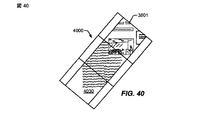
図39では、電子デバイス3801は、横方向モード3900において示され、ウェブブラウザアプリケーション画像が3つのディスプレイ面のすべてにわたって横方向タイプのディスプレイとして表示される。デバイス3801は、図40に示される遷移位置4000を通して、中間パネルの傾きを実質的に変更することなしに、図41に示されるプロファイルモード位置4100に反時計回りに回転され得る。たとえば、デバイス3801は、テーブルまたは机などの表面上に平坦に配置され得、回転され得る。別の例として、デバイス3801が回転されるとき、デバイス3801は、垂直な傾きなどの実質的に一定の傾きにおいて保持され得る。
In FIG. 39, the
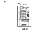
図40に示されるように、プロセッサ3830が、デバイス3801が面内回転方向3822において回転するが、縦回転方向3812において著しくは回転しないことを示す、加速度計3820およびインクリノメータ3810からの入力を受信するとき、ディスプレイパネルに表示された画像は、閲覧者に対する画像の姿勢を維持するように断続的に再描画され得る。そのような再描画は、ディスプレイ面が、基礎をなす画像に対して窓のように機能する外観をユーザに与えることができ、窓は回転し、画像は固定のままである。図41は、図39の横方向タイプ構成から反時計回りに1/4回転だけデバイスを回転することによって達成される縦方向タイプ姿勢における電子デバイス3801を示す。したがって、ユーザは、ユーザがコンテンツを閲覧するための姿勢に満足するまで、デバイス3801を断続的に回転することができる。
As shown in FIG. 40,
特定の一実施形態では、ゲームアプリケーションは、ユーザがデバイス3801を回転することによって制御入力を与えるように、デバイス3801によって実行され得る。たとえば、運転アプリケーションは、展開されたディスプレイパネルにわたって、運転者から見たレース場を表示することができ、ユーザは、レース場の車両のステアリングを制御するハンドルとしてデバイス3801を回転させることができ、ビューは、デバイスとともに回転せず、代わりに、実質的に固定の、ユーザの視点からの姿勢のままである。さらに、いくつかの状況では、デバイス3801の検出された回転は、ディスプレイの連続再描画に加えて、特定のプロセスを開始するために使用され得る。たとえば、デバイス3801がゲームアプリケーションを実行しているとき、検出された回転はデバイス3801の1つまたは複数の振動アクチュエータ(図示されず)または他のハードウェア要素をトリガすることができる。
In one particular embodiment, the gaming application may be executed by
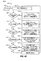
図42は、マルチパネル電子デバイスにおいてソフトウェア状態を変更する方法4200の第2の例示的な実施形態のフローチャートである。特定の一実施形態では、方法4200は、図1〜図7の電子デバイス101、図8の電子デバイス800、図9〜図14の電子デバイス900、図15〜図17の電子デバイス1501、図18〜図20の電子デバイス1801、図21の電子デバイス2100、図22〜図23の電子デバイス2201、図24および図25の電子デバイス2401、図27〜図31の電子デバイス2701、図32〜図37の電子デバイス3201、図38〜図41の電子デバイス3801、またはそれらの任意の組合せにおいて実行され得る。
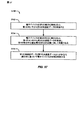
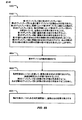
FIG. 42 is a flowchart of a second exemplary embodiment of a
方法4200は、デバイスが電源投入された後にユーザがアプリケーションを起動する前など、アプリケーションを実行するためのユーザインターフェースが表示されていないときの電子デバイスのデフォルト状態を示す。センサ入力4202が受信され、4204において新規のハードウェア形態を検出するために使用される。たとえば、センサ入力4202は、1つまたは複数のヒンジセンサ、インクリノメータ、加速度計、1つまたは複数の他のセンサ、またはそれらの任意の組合せなどを介して、マルチパネルデバイスの1つまたは複数のパネルの相対姿勢、または姿勢の変化を示すことがある。
判断4206に移動すると、4206において、デバイスが完全折り畳み形態にあるかどうかの判断が行われる。デバイスが完全折り畳み形態にあると判断された場合、4208において、アイコンパネルがアクティブスクリーンに表示され得、他のスクリーンが電源切断され得る。
Moving to
デバイスが完全折り畳み形態にないと判断された場合、判断4210において、デバイスがサミング構成にあるかどうかの判断が行われる。デバイスがサミング構成にあると判断された場合、4212において、デスクトップアイコンが上部の2つの閲覧スクリーンに表示され得、下部スクリーンにキーボードが表示され得る。
If it is determined that the device is not in the fully folded configuration, a determination is made at
デバイスがサミング構成にないと判断された場合、判断4214において、デバイスがトラベルクロック構成にあるかどうかの判断が行われる。デバイスがトラベルクロック構成にあると判断された場合、4216において、クロックが中間スクリーンに表示され得、クロックモードコントロールが水平スクリーンに表示され得、背面スクリーンが電源切断され得る。
If it is determined that the device is not in the summing configuration, a
デバイスがトラベルクロック構成にないと判断された場合、判断4218において、デバイスが完全展開形態にあるかどうかの判断が行われる。デバイスが完全展開形態にあると判断された場合、4220において、アイコンパネルが左端スクリーンに表示され得、他の2つのスクリーンはアプリケーションのためにクリアなままにされ得る。
If it is determined that the device is not in the travel clock configuration, at
デバイスが完全展開形態にないと判断された場合、判断4222において、デバイスがビデオ会議構成にあるかどうかの判断が行われる。デバイスがビデオ会議構成にあると判断された場合、4224において、ビデオ会議ビデオがアクティブスクリーンの上部に表示され得、ビデオ会議モードコントロールがアクティブスクリーンの下部に表示され得、他のスクリーンは電源切断され得る。
If it is determined that the device is not in the fully deployed configuration, at
デバイスがビデオ会議構成にないと判断された場合、4226において、デバイスが遷移構成にあるという判断が行われ得、ディスプレイパネルにおいて変更は実行され得ず、処理は4204に戻り得る。 If it is determined that the device is not in the video conferencing configuration, a determination can be made at 4226 that the device is in the transition configuration, no changes can be performed on the display panel, and the process can return to 4204.
方法4200は5つのハードウェア構成を示すが、他の実施形態では、6つ以上の構成または5つ未満の構成が使用され得る。たとえば、折り畳みスクリーンに似ている直立構成は、電子デバイスに、2次デスクトップ機器として使用するために、ワイヤレスデータネットワークを介して受信されたストリーミングリアルタイムニュース、株価、およびブログフィードを自動的に表示し始めること、またはデバイスにおいて記憶されたプレイリストまたはデータネットワークを介して受信されたプレイリストを再生し始めるオーディオまたはビデオファイルプレーヤを起動すること、またはユーザ構成に従って他のアプリケーションを自動的に起動すること、あるいはそれらの任意の組合せを行わせことができる。さらに、カスタム構成は、電子デバイス中にプログラムされ得、センサ入力4202が受信されたときに備えてテストされ得る。
Although
図43は、マルチパネル電子デバイスにおいてソフトウェア状態を変更する方法4300の第3の例示的な実施形態のフローチャートである。特定の一実施形態では、方法4300は、図1〜図7の電子デバイス101、図8の電子デバイス800、図9〜図14の電子デバイス900、図15〜図17の電子デバイス1501、図18〜図20の電子デバイス1801、図21の電子デバイス2100、図22〜図23の電子デバイス2201、図24および図25の電子デバイス2401、図27〜図31の電子デバイス2701、図32〜図37の電子デバイス3201、図38〜図41の電子デバイス3801、またはそれらの任意の組合せにおいて実行され得る。
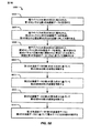
FIG. 43 is a flowchart of a third exemplary embodiment of a
方法4300は、複数のソフトウェア状態をサポートし、電子デバイスの構成変更に応答するアプリケーションが動作しているときの電子デバイスのデフォルト状態を示す。アクティブアプリケーションを実行している間、センサ入力4302が受信され、4304において新規のハードウェア構成を検出するために使用される。たとえば、センサ入力4302は、1つまたは複数のヒンジセンサ、インクリノメータ、加速度計、1つまたは複数の他のセンサ、またはそれらの任意の組合せなどを介して、マルチパネルデバイスの1つまたは複数のパネルの相対姿勢、または姿勢の変化を示すことがある。
The
判断4306に移動すると、4306において、デバイスが完全折り畳み形態にあるかどうかの判断が行われる。デバイスが完全折り畳み形態にあると判断された場合、アプリケーションがシングルスクリーン構成をサポートすれば、4308において、シングルスクリーンモードにおける、アプリケーションのアプリケーションウィンドウがアクティブスクリーンに表示され、他のスクリーンは電源切断される。アプリケーションがシングルスクリーンモードをサポートしない場合、アプリケーションは中断され、アクティブスクリーンに表示され得ない。
Moving to
デバイスが完全折り畳み形態にないと判断された場合、判断4310において、デバイスがサミング構成にあるかどうかの判断が行われる。デバイスがサミング構成にあると判断された場合、4312において、アプリケーションウィンドウが2パネル有効スクリーンに表示され得、キーボードが下部スクリーンに表示される。
If it is determined that the device is not in the fully folded configuration, a determination is made at
デバイスがサミング構成にないと判断された場合、判断4314において、デバイスがトラベルクロック構成にあるかどうかの判断が行われる。デバイスがトラベルクロック構成にあると判断された場合、アプリケーションがトラベルクロック構成をサポートすれば、4316において、中間スクリーン上のクロックまたは水平スクリーン上のクロックモードコントロール、あるいは両方をもつアプリケーションインターフェースが表示され、背面スクリーンは電源切断される。アプリケーションがトラベルクロック構成をサポートしない場合、アプリケーションは中断され得、表示され得ない。
If it is determined that the device is not in the summing configuration, at
デバイスがトラベルクロック構成にないと判断された場合、判断4318において、デバイスが完全展開形態にあるかどうかの判断が行われる。デバイスが完全展開形態にあると判断された場合、アプリケーションが完全展開形態をサポートすれば、4320において、アプリケーションウィンドウが3つのスクリーンのすべてにわたって表示され得る。アプリケーションが完全展開形態をサポートしなければ、アプリケーションウィンドウが1つまたは複数のスクリーンに表示され得る。
If it is determined that the device is not in the travel clock configuration, a determination is made at
デバイスが完全展開形態にないと判断された場合、判断4322において、デバイスがビデオ会議構成にあるかどうかの判断が行われる。デバイスがビデオ会議構成にあると判断された場合、アプリケーションがビデオ会議構成をサポートすれば、4324において、アクティブスクリーンの上部のビデオおよび/またはアクティブスクリーンの下部のビデオ会議モードコントロールをもつアプリケーションインターフェースが表示され得、他のスクリーンは電源切断され得る。アプリケーションがビデオ会議構成をサポートしなければ、アプリケーションは中断され得る。
If it is determined that the device is not in the fully deployed configuration, a determination is made at
デバイスがビデオ会議構成にないと判断された場合、4326において、デバイスが遷移構成にあるという判断が行われ得、ディスプレイパネルにおいて変更は実行され得ず、処理は4304に戻り得る。 If it is determined that the device is not in the video conferencing configuration, a determination may be made at 4326 that the device is in the transition configuration, no changes may be performed on the display panel, and the process may return to 4304.
特定の一実施形態では、アプリケーションによってサポートされない1つまたは複数の構成において、アプリケーションが中断された場合、アプリケーションが中断されたことを示すために1つまたは複数のアイコンまたは他のインジケータが表示され得る。別の実施形態では、アプリケーションを中断するのではなく、アプリケーションは実行され続け得るが、グラフィカルユーザインターフェースは表示され得ない。たとえば、デバイスが、オーディオファイルプレーヤによってサポートされない構成に変更されると、オーディオファイルプレーヤのためのインターフェースは表示され得ないが、オーディオファイルプレーヤはプレイリストを再生し続けることができる。別の実施形態では、アプリケーションは、アプリケーションによってサポートされない構成への遷移に応答して、中断され得るのではなく、自動終了され得る。別の実施形態では、アプリケーションは、アプリケーションが中断されるべきか自動終了されるべきかを制御する構成データを含むことができる。 In one particular embodiment, in one or more configurations that are not supported by the application, if the application is suspended, one or more icons or other indicators may be displayed to indicate that the application has been suspended. . In another embodiment, rather than interrupting the application, the application may continue to run, but the graphical user interface may not be displayed. For example, if the device is changed to a configuration that is not supported by the audio file player, the interface for the audio file player cannot be displayed, but the audio file player can continue to play the playlist. In another embodiment, the application may be auto-terminated rather than interrupted in response to a transition to a configuration not supported by the application. In another embodiment, the application can include configuration data that controls whether the application should be interrupted or automatically terminated.
特定の一実施形態では、デバイスは、構成変更を検出することに基づいて、他の動作を実行することができる。たとえば、図48に関して論じられるように、ブラウザウィンドウが開き、特定のウェブサイトからのコンテンツを表示するとき、デバイスは、構成変更により増加または減少する利用可能な画面サイズまたは解像度に基づいてコンテンツを再送信するように、ウェブサイトに自動的に要求することができる。別の例として、ビデオプレーヤは、完全展開形態から、完全折り畳み、トラベルクロック、またはサミング構成などへの構成変更により、利用可能な画面サイズが縮小されると、ワイドスクリーンディスプレイモードから低解像度ナローディスプレイモードに自動的に変化することができる。 In one particular embodiment, the device may perform other operations based on detecting configuration changes. For example, as discussed with respect to FIG. 48, when a browser window opens and displays content from a particular website, the device replays the content based on available screen sizes or resolutions that increase or decrease due to configuration changes. The website can be automatically requested to send. As another example, a video player may change from a wide screen display mode to a low resolution narrow display when the available screen size is reduced, such as by changing the configuration from a fully expanded configuration to a fully folded, travel clock, or summing configuration. Can change to mode automatically.
方法4300は5つのハードウェア構成を示すが、他の実施形態では、6つ以上の構成または5つ未満の構成が使用され得る。たとえば、折り畳みスクリーンに似ている直立構成は、電子デバイスに、2次デスクトップ機器として使用するために、左端パネルにアプリケーションのためのアプリケーションインターフェースを表示すること、ならびに中心および右端パネルに、ワイヤレスデータネットワークを介して受信されたストリーミングリアルタイムニュース、株価、およびブログフィードを自動的に表示し始めることを行わせことができる。さらに、カスタム構成は、電子デバイスにプログラムされ得、センサ入力4302が受信されたときに備えてテストされ得る。
Although the
さらに、図42および図43に示される実施形態の一方または両方は、追加の構成判断を含むことができる。たとえば、方法4200、4300、または両方は、デバイスが縦方向姿勢にあるか、横方向姿勢にあるか、または(たとえば、図38〜図41に関して説明されたように)回転姿勢にあるかの1つまたは複数の判断を含むことができる。判断に基づいて、デバイスは、追加のソフトウェア構成およびユーザインターフェースの変更を行うことができる。例示するために、センサ入力4202または4302が、デバイスが完全展開形態にあることを示し、アクティブアプリケーションがビデオプレーヤであるとき、ビデオは、デバイスが横方向姿勢にある(たとえば、デバイスが上下方向よりも左右方向のほうが長くなるようにデバイスが保持されている)ことを検出されると、3つのスクリーンのすべてにわたって表示され得るが、デバイスが縦方向姿勢にある(たとえば、デバイスが左右方向よりも上下方向のほうが長くなるようにデバイスが保持されている)ことを検出されると、上部の2つのスクリーンにのみ表示され得る。特定の一実施形態では、ビデオは利用可能なディスプレイエリアにわたるように伸張され得るが、別の実施形態では、表示中にビデオのアスペクト比が保持され得る。
Furthermore, one or both of the embodiments shown in FIGS. 42 and 43 can include additional configuration decisions. For example,
図44は、マルチパネル電子デバイスにおいてソフトウェア状態を変更する方法4400の第4の例示的な実施形態のフローチャートである。特定の一実施形態では、方法4400は、図1〜図7の電子デバイス101、図8の電子デバイス800、図9〜図14の電子デバイス900、図15〜図17の電子デバイス1501、図18〜図20の電子デバイス1801、図21の電子デバイス2100、図22〜図23の電子デバイス2201、図24および図25の電子デバイス2401、図27〜図31の電子デバイス2701、図32〜図37の電子デバイス3201、図38〜図41の電子デバイス3801、またはそれらの任意の組合せにおいて実行され得る。
FIG. 44 is a flowchart of a fourth exemplary embodiment of a
4402において、第1の形態から第2の形態へのハードウェア構成変更が電子デバイスにおいて検出される。電子デバイスは、少なくとも、第1のディスプレイ面を有する第1のパネルと、第2のディスプレイ面を有する第2のパネルとを含む。ハードウェア構成変更は、第2のディスプレイパネルに対する第1のディスプレイパネルの相対姿勢の変更を含む。4404に進むと、第1のディスプレイ面と第2のディスプレイ面とに表示されたグラフィカルユーザインターフェースは、第2の形態に少なくとも部分的に基づいて自動的に修正される。 At 4402, a hardware configuration change from the first configuration to the second configuration is detected at the electronic device. The electronic device includes at least a first panel having a first display surface and a second panel having a second display surface. The hardware configuration change includes a change in the relative posture of the first display panel with respect to the second display panel. Proceeding to 4404, the graphical user interface displayed on the first display surface and the second display surface is automatically modified based at least in part on the second configuration.
特定の一実施形態では、第1のパネルは、第2のパネルの第1のヒンジ式エッジに沿って第2のパネルに回転可能に結合され、第3のパネルは、第2のパネルの第2のヒンジ式エッジに沿って第2のパネルに回転可能に結合され、第3のパネルは第3のディスプレイ面を有する。 In one particular embodiment, the first panel is rotatably coupled to the second panel along the first hinged edge of the second panel, and the third panel is the second panel's second A second panel is rotatably coupled to the second panel along two hinged edges, the third panel having a third display surface.
特定の一実施形態では、第1のパネルは第1のディスプレイ面の反対側に第1の裏面を有し、第2のパネルは第2のディスプレイ面の反対側に第2の裏面を有し、第3のパネルは第3のディスプレイ面の反対側に第3の裏面を有する。第2の形態は、第2の裏面に近接した第1の裏面と、第3のディスプレイ面に近接した第2のディスプレイ面とを有する折り畳み形態を含むことができる。グラフィカルユーザインターフェースは、第1のディスプレイ面に表示し、第2のディスプレイ面または第3のディスプレイ面には表示しないように自動的に修正され得る。たとえば、第2の形態は図2の完全折り畳み形態200であり得る。
In one particular embodiment, the first panel has a first back surface opposite the first display surface and the second panel has a second back surface opposite the second display surface. The third panel has a third back surface opposite the third display surface. The second configuration can include a folded configuration having a first back surface proximate to the second back surface and a second display surface proximate to the third display surface. The graphical user interface may be automatically modified to display on the first display surface and not on the second display surface or the third display surface. For example, the second configuration may be the fully folded
別の実施形態では、第2の形態は、第2のパネルとほぼ同一平面である第1のパネルを有し、第3のパネルとほぼ同一平面である第2のパネルを有する完全展開形態を含む。第1のディスプレイ面と、第2のディスプレイ面と、第3のディスプレイ面とは、第1のパネルと、第2のパネルと、第3のパネルとにわたって展開する実質的に連続的なディスプレイ面を形成することができる。グラフィカルユーザインターフェースは、実質的に連続的なディスプレイ面にわたって表示されるグラフィカル要素を拡張するように自動的に修正され得る。たとえば、第2の形態はそれぞれ図5または図6の完全展開形態500であり得る。
In another embodiment, the second configuration has a fully deployed configuration having a first panel that is substantially flush with the second panel and a second panel that is substantially flush with the third panel. Including. The first display surface, the second display surface, and the third display surface are substantially continuous display surfaces that extend across the first panel, the second panel, and the third panel. Can be formed. The graphical user interface can be automatically modified to extend the graphical elements displayed across a substantially continuous display surface. For example, the second configuration can be the fully deployed
別の実施形態では、第2の形態は、実質的に連続的な2パネルディスプレイ面を形成するために、第2のパネルとほぼ同一平面である第1のパネルを含む。第2の形態はまた、第2のディスプレイ面と第3のディスプレイ面とによって形成される角度が90度よりも大きく、180度未満であるように配置される第3のパネルを含むことができる。角度は約135度である。グラフィカルユーザインターフェースは、キーボードを第3のディスプレイ面に表示し、他のインターフェース要素を実質的に連続的な2パネルディスプレイ面に表示するように自動的に修正され得る。たとえば、第2の形態は図3のサミング構成300であり得る。
In another embodiment, the second form includes a first panel that is substantially flush with the second panel to form a substantially continuous two-panel display surface. The second form may also include a third panel arranged such that the angle formed by the second display surface and the third display surface is greater than 90 degrees and less than 180 degrees. . The angle is about 135 degrees. The graphical user interface may be automatically modified to display a keyboard on a third display surface and other interface elements on a substantially continuous two-panel display surface. For example, the second configuration may be the summing
別の実施形態では、第2の形態は、第1のディスプレイ面と第2のディスプレイ面とによって形成される第1の角度が約270度になるように配置された第1のパネルと第2のパネルとを含み、第2のディスプレイ面と第3のディスプレイ面とによって形成される第2の角度は約135度である。グラフィカルユーザインターフェースは、第2のディスプレイパネルにクロックを表示するように自動的に修正され得る。たとえば、第2の形態は図4のトラベルクロック構成400であり得る。 In another embodiment, the second form includes a first panel and a second panel arranged such that a first angle formed by the first display surface and the second display surface is about 270 degrees. The second angle formed by the second display surface and the third display surface is about 135 degrees. The graphical user interface can be automatically modified to display the clock on the second display panel. For example, the second form may be travel clock configuration 400 of FIG.
別の実施形態では、第2の形態はビデオ会議構成であり、第1のパネルと第2のパネルとはほぼ同一平面であり、第3のパネルは、第2のディスプレイ面が第3のディスプレイ面に近接するように第2のパネル上に折り畳まれ、第3のパネルの裏面内に格納されたカメラが、デバイスのユーザの画像をキャプチャする視界を有する。グラフィカルユーザインターフェースは、第1のディスプレイ面にビデオ画像を表示し、第2のディスプレイ面または第3のディスプレイ面には表示しないように自動的に修正され得る。たとえば、第2の形態は図7のビデオ会議構成700であり得る。
In another embodiment, the second form is a video conferencing configuration, wherein the first panel and the second panel are substantially coplanar, and the third panel has a second display surface on the third display. A camera that is folded onto the second panel so as to be close to the surface and stored within the back surface of the third panel has a field of view that captures an image of the user of the device. The graphical user interface may be automatically modified to display a video image on the first display surface and not on the second or third display surface. For example, the second form may be the
図45は、マルチパネル電子デバイスにおいてソフトウェア状態を変更する方法4500の第5の例示的な実施形態のフローチャートである。特定の一実施形態では、方法4500は、図1〜図7の電子デバイス101、図8の電子デバイス800、図9〜図14の電子デバイス900、図15〜図17の電子デバイス1501、図18〜図20の電子デバイス1801、図21の電子デバイス2100、図22〜図23の電子デバイス2201、図24および図25の電子デバイス2401、図27〜図31の電子デバイス2701、図32〜図37の電子デバイス3201、図38〜図41の電子デバイス3801、またはそれらの任意の組合せにおいて実行され得る。
FIG. 45 is a flowchart of a fifth exemplary embodiment of a
4502において、電子デバイスの第1のディスプレイ面においてグラフィカルユーザインターフェース要素を移動するユーザ入力が受信される。電子デバイスは、間隙によって第1のディスプレイ面から分離されている第2のディスプレイ面をさらに含む。4504に移動すると、グラフィカルユーザインターフェース要素の少なくとも一部分が第1のディスプレイ面のエッジを離れて間隙のほうへ移動されるべきであるという判断が行われる。4506に進むと、第1のディスプレイ面におけるグラフィカルユーザインターフェース要素の配置と移動方向とに基づいて、グラフィカルユーザインターフェース要素の少なくとも一部分が第2のディスプレイ面に表示される。 At 4502, user input for moving a graphical user interface element on a first display surface of an electronic device is received. The electronic device further includes a second display surface that is separated from the first display surface by a gap. Moving to 4504, a determination is made that at least a portion of the graphical user interface element should be moved off the edge of the first display surface and toward the gap. Proceeding to 4506, at least a portion of the graphical user interface element is displayed on the second display surface based on the placement and direction of movement of the graphical user interface element on the first display surface.
たとえば、グラフィカルユーザインターフェース要素は、左端ディスプレイ面に表示される第1の部分を有し、間隙3414を越えて移動3412中に中心ディスプレイ面に表示される第2の部分を有するように図34中に表示されるアイコン3206などのアプリケーションアイコンであり得る。別の例として、グラフィカルユーザインターフェース要素は、左端ディスプレイ面に表示される第1の部分を有し、間隙3414を越えて移動3618中に中心ディスプレイ面に表示される第2の部分を有するように図36中に表示されるウィンドウ3516などのアプリケーションウィンドウであり得る。
For example, in FIG. 34 the graphical user interface element has a first portion displayed on the leftmost display surface and a second portion displayed on the central display surface during
図46は、マルチパネル電子デバイスにおいてソフトウェア状態を変更する方法4600の第6の例示的な実施形態のフローチャートである。特定の一実施形態では、方法4600は、図1〜図7の電子デバイス101、図8の電子デバイス800、図9〜図14の電子デバイス900、図15〜図17の電子デバイス1501、図18〜図20の電子デバイス1801、図21の電子デバイス2100、図22〜図23の電子デバイス2201、図24および図25の電子デバイス2401、図27〜図31の電子デバイス2701、図32〜図37の電子デバイス3201、図38〜図41の電子デバイス3801、またはそれらの任意の組合せにおいて実行され得る。
FIG. 46 is a flowchart of a sixth exemplary embodiment of a
4602において、電子デバイスの第1のディスプレイ面においてアプリケーションアイコンを移動するユーザ入力が受信される。電子デバイスは、間隙によって第1のディスプレイ面から分離されている第2のディスプレイ面をさらに含む。たとえば、ユーザ入力は、第1のディスプレイ面におけるタッチスクリーンにおけるアプリケーションアイコンのドラッグ操作を含むことができる。例示的な一実施形態では、アプリケーションアイコンは図32〜図35のアイコン3206である。
At 4602, user input for moving an application icon on a first display surface of an electronic device is received. The electronic device further includes a second display surface that is separated from the first display surface by a gap. For example, the user input can include a drag operation of an application icon on the touch screen on the first display surface. In one exemplary embodiment, the application icon is
4604に進むと、アプリケーションアイコンが、ユーザ入力に基づいて第1のディスプレイ面のエッジを離れて間隙のほうへ移動されるべきであるという判断が行われる。たとえば、アイコン3206は、図34に示されるように間隙3414のほうへ移動され得る。4606に進むと、アプリケーションアイコンが第1のディスプレイのエッジを離れて移動されることに応答して、アプリケーションアイコンに関連付けられたアプリケーションが起動される。4608に進むと、アプリケーションアイコンに関連付けられたアプリケーションのためのユーザインターフェースの少なくとも一部分は、図35に示される第2のディスプレイ面3308におけるアプリケーションウィンドウ3516など、第2のディスプレイ面に表示される。
Proceeding to 4604, a determination is made that the application icon should be moved off the edge of the first display surface and toward the gap based on user input. For example,
図47は、マルチパネル電子デバイスにおいてソフトウェア状態を変更する方法4700の第7の例示的な実施形態のフローチャートである。特定の一実施形態では、方法4700は、図1〜図7の電子デバイス101、図8の電子デバイス800、図9〜図14の電子デバイス900、図15〜図17の電子デバイス1501、図18〜図20の電子デバイス1801、図21の電子デバイス2100、図22〜図23の電子デバイス2201、図24および図25の電子デバイス2401、図27〜図31の電子デバイス2701、図32〜図37の電子デバイス3201、図38〜図41の電子デバイス3801、またはそれらの任意の組合せにおいて実行され得る。
FIG. 47 is a flowchart of a seventh exemplary embodiment of a
4702において、複数のアプリケーションアイコンが電子デバイスの第1のディスプレイ面に表示され、アプリケーションのためのアプリケーションインターフェースウィンドウが電子デバイスの第2のディスプレイ面に表示される。第1のディスプレイ面は、間隙によって第2のディスプレイ面から分離されている。例示的な一実施形態では、アプリケーションインターフェースウィンドウは、図35に示されるように、間隙3414によってアプリケーションアイコンから分離された第2のディスプレイ面3308におけるアプリケーションウィンドウ3516であり得る。
At 4702, a plurality of application icons are displayed on the first display surface of the electronic device, and an application interface window for the application is displayed on the second display surface of the electronic device. The first display surface is separated from the second display surface by a gap. In one exemplary embodiment, the application interface window may be an
4704に移動すると、第2のディスプレイ面におけるアプリケーションインターフェースウィンドウの少なくとも一部分を移動するユーザ入力が受信される。たとえば、ユーザ入力は、第2のディスプレイ面におけるタッチスクリーンにおけるアプリケーションアイコンのドラッグ操作を含むことができる。4706に進むと、アプリケーションインターフェースウィンドウの少なくとも一部分が、ユーザ入力に基づいて第2のディスプレイ面のエッジを離れて間隙のほうへ移動されるべきであるという判断が行われる。4708に進むと、図36〜図37においてアプリケーションウィンドウ3516が間隙3414を越えて移動されるものとして示されるように、アプリケーションインターフェースウィンドウの部分が第2のディスプレイ面のエッジを離れて移動されることに応答して、アプリケーションインターフェースウィンドウが閉じられる。
Moving to 4704, user input is received moving through at least a portion of the application interface window on the second display surface. For example, the user input can include a drag operation of an application icon on the touch screen on the second display surface. Proceeding to 4706, a determination is made that at least a portion of the application interface window should be moved off the edge of the second display surface and toward the gap based on user input. Proceeding to 4708, a portion of the application interface window is moved off the edge of the second display surface, as shown in FIGS. 36-37 as
4710に進むと、特定の一実施形態では、アプリケーションインターフェースウィンドウの部分が第2のディスプレイのエッジを離れて移動されることに応答して、アプリケーションに関連付けられたアプリケーションアイコンが第1のディスプレイ面に表示される。たとえば、アプリケーションウィンドウ3516の部分が間隙3414を越えて移動された後のアプリケーションアイコン3206は、図37中に表示される。4712に進むと、特定の一実施形態では、アプリケーションインターフェースウィンドウの部分が第2のディスプレイのエッジを離れて移動されることに応答して、アプリケーションが閉じられる。
Proceeding to 4710, in one particular embodiment, in response to the portion of the application interface window being moved off the edge of the second display, an application icon associated with the application is displayed on the first display surface. Is displayed. For example, the
図48は、マルチパネル電子デバイスにおいてソフトウェア状態を変更する方法4800の第8の例示的な実施形態のフローチャートである。画面サイズと画面解像度とに応じて、マルチパネル電子デバイスにおけるウェブブラウザは、ウェブブラウザがウェブサーバにそれ自体を提示する方法を自動的に変更することができる。電子デバイスのパネルを折り畳むことまたは展開することなどによって画面サイズおよび/または画面解像度が変化すると、現在のウェブサイトは、新しいブラウザ識別パラメータに対してサービスされるウェブサイトで自動的にリフレッシュされ得る。ユーザは折り畳み形態を変更することによってデバイスのパラメータを変更し、デバイスは、ウェブサイトが、デバイスの新しいパラメータに適し得るウェブコンテンツを自動的にサービスすることを可能にする情報を、自動的に送信することができる。
FIG. 48 is a flowchart of an eighth exemplary embodiment of a
特定の一実施形態では、方法4800は、図1〜図7の電子デバイス101、図8の電子デバイス800、図9〜図14の電子デバイス900、図15〜図17の電子デバイス1501、図18〜図20の電子デバイス1801、図21の電子デバイス2100、図22〜図23の電子デバイス2201、図24および図25の電子デバイス2401、図27〜図31の電子デバイス2701、図32〜図37の電子デバイス3201、図38〜図41の電子デバイス3801、またはそれらの任意の組合せにおいて実行され得る。
In one particular embodiment, the
4802において、第1の形態から第2の形態へのハードウェア構成変更が電子デバイスにおいて検出される。電子デバイスは、少なくとも、第1のディスプレイ面を有する第1のパネルと、第2のディスプレイ面を有する第2のパネルとを含む。第1のディスプレイ面および第2のディスプレイ面の閲覧エリアに対応する有効画面サイズまたは画面解像度のうちの少なくとも1つは、ハードウェア構成変更に応答して修正される。たとえば、第1のパネルはヒンジを介して第2のパネルに結合され得、ハードウェア構成変更は第2のパネルに対する第1のパネルの相対姿勢の変化を含むことができる。 At 4802, a hardware configuration change from the first configuration to the second configuration is detected in the electronic device. The electronic device includes at least a first panel having a first display surface and a second panel having a second display surface. At least one of the effective screen size or the screen resolution corresponding to the viewing area of the first display surface and the second display surface is modified in response to the hardware configuration change. For example, the first panel can be coupled to the second panel via a hinge, and the hardware configuration change can include a change in the relative orientation of the first panel relative to the second panel.
4804に移動すると、ハードウェア構成変更、すなわち修正された有効画面サイズまたは修正された画面解像度のうちの少なくとも1つに基づく少なくとも1つのパラメータに応答して、少なくとも1つのパラメータがウェブサーバに送信される。 Moving to 4804, in response to at least one parameter based on a hardware configuration change, ie, at least one of a modified effective screen size or a modified screen resolution, at least one parameter is sent to the web server. The
特定の一実施形態では、少なくとも1つのパラメータはブラウザ設定を示す。4806に進むと、ハードウェア構成変更に基づいてブラウザインターフェースが自動的に修正され得る。4808に進むと、ウェブサーバから修正されたコンテンツが受信され得、修正されたコンテンツは、ブラウザ設定に基づいて表示されるようにフォーマットされている。4810に進むと、修正されたブラウザインターフェースに修正されたコンテンツが表示され得る。 In one particular embodiment, the at least one parameter indicates browser settings. Proceeding to 4806, the browser interface may be automatically modified based on the hardware configuration change. Proceeding to 4808, modified content may be received from the web server, and the modified content is formatted to be displayed based on browser settings. Proceeding to 4810, the modified content may be displayed in a modified browser interface.
電子デバイスは、ハードウェア構成変更を検出することに応答して、追加のユーザ入力を受信することなしに、少なくとも1つのパラメータを送信し、ブラウザインターフェースを自動的に修正し、修正されたコンテンツを表示するように構成され得る。例示するために、ブラウザアプリケーションが動作している間に図1の電子デバイス101が図2の完全折り畳み形態200に折り畳まれると、デバイス101は、第1の面102に表示するようにブラウザを自動的に構成することができ、モバイルブラウザタイプとしてウェブブラウザを識別することなどによって、ブラウザに表示されるコンテンツを与えているウェブサーバに、縮小されたページコンテンツをもつモバイルデバイスウェブページの要求を送信することができる。デバイス101が図5の完全展開形態500または図6の600に変更されると、デバイス101は、デスクトップブラウザタイプまたはラップトップブラウザタイプとしてウェブブラウザを識別することなどによって、3つのディスプレイ面102〜106のすべてにわたって表示するようにブラウザを自動的に構成することができ、提供するウェブサーバに対して、より多くのコンテンツをもつデスクトップタイプウェブページの要求を送信することができる。
In response to detecting the hardware configuration change, the electronic device sends at least one parameter and automatically modifies the browser interface to receive the modified content without receiving additional user input. Can be configured to display. To illustrate, when the
図49を参照すると、加速度計を有する電子デバイス4901の特定の例示的な実施形態が示され、全体的に4900と称される。特定の一実施形態では、電子デバイス4901は、図1〜図7の電子デバイス101、図8の電子デバイス800、図9〜図14の電子デバイス900の3パネルバージョン、図15〜図17の電子デバイス1501、図18〜図20の電子デバイス1801、図21の電子デバイス2100、図22〜図23の電子デバイス2201、図24および図25の電子デバイス2401、図27〜図31の電子デバイス2701、図32〜図37の電子デバイス3201、図38〜図41の電子デバイス3801、またはそれらの任意の組合せである。特定の一実施形態では、電子デバイス4901は、図26の方法2600、図42の方法4200、図43の方法4300、図44の方法4400、図45の方法4500、図46の方法4600、図47の方法4700、図48の方法4800、またはそれらの任意の組合せに従って動作するように構成される。
Referring to FIG. 49, a particular exemplary embodiment of an
電子デバイス4901は、第1のディスプレイ面4908を有する第1のパネル4902と、第2のディスプレイ面4910を有する第2のパネル4904と、第3のディスプレイ面4912を有する第3のパネル4906とを含む。3つのディスプレイ面4908〜4912は、すべての3つのディスプレイ面4908〜4912にわたって展開する単一のディスプレイスクリーンをエミュレートするように制御され得る。第1のパネル4902は第2のパネル4904の第1のエッジに回転可能に結合され、第3のパネル4906は第2のパネル4904の第2のエッジに回転可能に結合される。第1の加速度計4922は第1のパネル4902に配置され、第2の加速度計4924は第2のパネル4904に配置され、第3の加速度計4926は第3のパネル4906に配置される。姿勢モジュール4994は、第1の加速度計4922から第1の加速度データ4982を受信するために結合される。姿勢モジュール4994は、第2の加速度計4924から第2の加速度データ4984を受信するために結合される。姿勢モジュール4994は、第3の加速度計4926から第3の加速度データ4986を受信するために結合される。プロセッサ4998などのコントローラは、矢印4996で示されるように姿勢モジュール4994に結合される。相互に直交する軸X1、Y1、およびZ1は、第1の加速度計4922に関連付けられる。相互に直交する軸X2、Y2、およびZ2は、第2の加速度計4924に関連付けられる。相互に直交する軸X3、Y3、およびZ3は、第3の加速度計4926に関連付けられる。
The
第1の加速度計4922は、第1のパネル4902に結合され、第1のパネル4902の加速度に関係付けられる第1の加速度データ4982を生成するように構成され得る。第2の加速度計4924は、第2のパネル4904に結合され、第2のパネル4904の加速度に関係付けられる第2の加速度データ4984を生成するように構成され得る。第3の加速度計4926は、第3のパネル4906に結合され、第3のパネル4906の加速度に関係付けられる第3の加速度データ4986を生成するように構成され得る。姿勢モジュール4994は、第1の加速度計4922から受信された第1の加速度データ4982と、第2の加速度計4924から受信された第2の加速度データ4984と、第3の加速度計4926から受信された第3の加速度データ4986とに少なくとも部分的に基づいて電子デバイス4901の構成を判断するように構成され得る。
The
特定の一実施形態では、姿勢モジュール4994は、重力の方向に対する第1のディスプレイ面4908の第1の姿勢と、重力の方向に対する第2のディスプレイ面4910の第2の姿勢と、重力の方向に対する第3のディスプレイ面4912の第3の姿勢とに基づいて電子デバイス4901の構成を判断するように構成される。特定の一実施形態では、プロセッサ4998は、電子デバイス4901の構成の検出された変化に基づいて、第1のディスプレイ面4908、第2のディスプレイ面4910、および第3のディスプレイ面4912のうちの少なくとも1つに提供されるグラフィカルユーザインターフェース(GUI)を自動的に調整するように構成される。
In one particular embodiment,
図50を参照すると、完全展開形態における図49の電子デバイス4901が示され、全体的に5000と称される。完全展開形態5000では、第1の加速度計4922によって感知される加速度は矢印5032によって示され、第2の加速度計4924によって感知される加速度は矢印5034によって示され、第3の加速度計4926によって感知される加速度は矢印5036によって示されている。加速度5032〜5036は、重力に起因し、すべて重力の方向にあり、第1の加速度計4922によれば負のZ1方向に、第2の加速度計4924によれば負のZ2方向に、第3の加速度計4926によれば負のZ3方向にある。加速度5032〜5036はまた、矢印5032〜5036のそれぞれの長さで表されるように実質的に同じ大きさである。
Referring to FIG. 50, the
図51を参照すると、完全折り畳み形態における図49の電子デバイス4901が示され、全体的に5100と称される。完全折り畳み形態5100では、第1の加速度計4922によって感知される加速度は矢印5132によって示され、第2の加速度計4924によって感知される加速度は矢印5134によって示され、第3の加速度計4926によって感知される加速度は矢印5136によって示されている。加速度5132〜5136は、重力に起因し、すべて重力の方向にあり、第1の加速度計4922によれば負のZ1方向に、第2の加速度計4924によれば正のZ2方向に、第3の加速度計4926によれば負のZ3方向にある。第2の加速度計4924によって感知される加速度5134の方向は、第1の加速度計4922によって感知される加速度5132の方向と反対であり、第3の加速度計4926によって感知される加速度5136の方向と反対である。完全折り畳み形態5100では、第2の加速度計4924は、第1の加速度計4922に対して、および第3の加速度計4926に対して「逆さま」である。加速度5132〜5136は、矢印5132〜5136のそれぞれの長さで表されるようにすべて実質的に同じ大きさである。
Referring to FIG. 51, the
図52を参照すると、サミング構成における図49の電子デバイス4901が示され、全体的に5200と称される。サミング構成5200では、第1の加速度計4922によって感知される加速度は矢印5232によって示され、第2の加速度計4924によって感知される加速度は矢印5234によって示され、第3の加速度計4926によって感知される加速度は矢印5236によって示されている。加速度5232〜5236は、重力に起因し、すべて重力の方向にあり、第1の加速度計4922によれば負のZ1方向にあり、第2の加速度計4924によれば重力成分5250は負のZ2方向に、重力成分5252は負のX2方向にあり、第3の加速度計4926によれば重力成分5240は負のZ3方向に、重力成分5242は負のX3方向にある。加速度5232〜5236は、矢印5232〜5236のそれぞれの長さで表されるようにすべて実質的に同じ大きさである。
Referring to FIG. 52, the
重力成分5240の大きさは、加速度5236と重力成分5242との間の角度の正弦と加速度5236の大きさとの積に等しい。たとえば、角度が30度である場合、重力成分5240の大きさは、加速度5236の大きさの1/2であり、また、加速度5232の大きさは加速度5236の大きさと同じなので加速度5232の大きさの1/2である。同様に、重力成分5250の大きさは、加速度5234と重力成分5252との間の角度の正弦と加速度5234の大きさとの積に等しい。たとえば、角度が30度である場合、重力成分5250の大きさは、加速度5234の大きさの1/2であり、また、加速度5234の大きさは加速度5232の大きさと同じなので加速度5232の大きさの1/2である。
The magnitude of the
図53を参照すると、ビデオ会議構成における図49の電子デバイス4901が示され、全体的に5300と称される。ビデオ会議構成5300では、第1の加速度計4922によって感知される加速度は矢印5332によって示され、第2の加速度計4924によって感知される加速度は矢印5334によって示され、第3の加速度計4926によって感知される加速度は矢印5336によって示されている。加速度5332〜5336は、重力に起因し、すべて重力の方向にあり、第1の加速度計4922によれば負のZ1方向に、第2の加速度計4924によれば負のZ2方向に、第3の加速度計4926によれば正のZ3方向にある。第3の加速度計4926によって感知される加速度5336の方向は、第1の加速度計4922によって感知される加速度5332の方向と反対であり、第2の加速度計4924によって感知される加速度5334の方向と反対である。ビデオ会議構成5300では、第3の加速度計4926は、第1の加速度計4922に対して、および第2の加速度計4924に対して「逆さま」である。加速度5332〜5336は、矢印5332〜5336のそれぞれの長さで表されるようにすべて実質的に同じ大きさである。
Referring to FIG. 53, the
図54を参照すると、トラベルクロック構成における図49の電子デバイス4901が示され、全体的に5400と称される。トラベルクロック構成5400では、第1の加速度計4922によって感知される加速度は矢印5432によって示され、第2の加速度計4924によって感知される加速度は矢印5434によって示され、第3の加速度計4926によって感知される加速度は矢印5436によって示されている。加速度5432〜5436は、重力に起因し、すべて重力の方向にあり、第1の加速度計4922によれば重力成分5440は負のZ1方向に、重力成分5442は負のX1方向にあり、第2の加速度計4924によれば重力成分5450は負のZ2方向に、重力成分5452は正のX2方向にあり、第3の加速度計4926によれば負のZ3方向にある。加速度5432〜5436は、矢印5432〜5436のそれぞれの長さで表されるようにすべて実質的に同じ大きさである。
Referring to FIG. 54, the
重力成分5440の大きさは、加速度5432と重力成分5442との間の角度の正弦と加速度5432の大きさとの積に等しい。たとえば、角度が30度である場合、重力成分5440の大きさは、加速度5432の大きさの1/2であり、また、加速度5432の大きさは加速度5436の大きさと同じなので加速度5436の大きさの1/2である。同様に、重力成分5450の大きさは、加速度5434と重力成分5452との間の角度の正弦と加速度5434の大きさとの積に等しい。たとえば、角度が30度である場合、重力成分5450の大きさは、加速度5434の大きさの1/2であり、また、加速度5434の大きさは加速度5436の大きさと同じなので加速度5436の大きさの1/2である。
The magnitude of the
図55を参照すると、デュアルパネル構成における図49の電子デバイス4901が示され、全体的に5500と称される。デュアルパネル構成5500では、第1の加速度計4922によって感知される加速度は矢印5532によって示され、第2の加速度計4924によって感知される加速度は矢印5534によって示され、第3の加速度計4926によって感知される加速度は矢印5536によって示されている。加速度5532〜5536は、重力に起因し、すべて重力の方向にあり、第1の加速度計4922によれば正のZ1方向に、第2の加速度計4924によれば負のZ2方向に、第3の加速度計4926によれば負のZ3方向にある。第1の加速度計4922によって感知される加速度5532の方向は、第2の加速度計4924によって感知される加速度5534の方向と反対であり、第3の加速度計4926によって感知される加速度5536の方向と反対である。デュアルパネル構成5500では、第1の加速度計4922は、第2の加速度計4924に対して、および第3の加速度計4926に対して「逆さま」である。加速度5532〜5536は、矢印5532〜5536のそれぞれの長さで表されるようにすべて実質的に同じ大きさである。
Referring to FIG. 55, the
特定の一実施形態では、図55に示されるデュアルパネル構成は、「ブックモード」として機能し、第2の加速度計4924と第3の加速度計4926とを含むパネルはブックの両面をシミュレートすることができる。そのようなブックモード構成では、第1の加速度計4922を含むパネルは、通常動作中にユーザから離れて後ろに折り畳まれ、エネルギー(たとえば、図8のバッテリー884および886によって供給されるエネルギー)を節約するためにオフにされ得る。図55に示される特定の構成はブックモードパネルをほぼ同一平面であるものとして示しているが、代わりに、さらにブックの中のテキストおよび画像を閲覧することをシミュレートするために、パネルは互いに向かってわずかに曲げられ得ることに留意されたい。
In one particular embodiment, the dual panel configuration shown in FIG. 55 functions as a “book mode”, and a panel including a
さらに、図1〜図7の電子デバイス101、図8の電子デバイス800、図9〜図14の電子デバイス900の3パネルバージョン、図15〜図17の電子デバイス1501、図18〜図20の電子デバイス1801、図21の電子デバイス2100、図22〜図23の電子デバイス2201、図24および図25の電子デバイス2401、図27〜図31の電子デバイス2701、図32〜図37の電子デバイス3201、ならびに図38〜図41の電子デバイス3801のうちの1つまたは複数は、前述された1つまたは複数の所定の構成に加えてブックモード構成において動作するようにも構成され得る。
Further, the
図56は、電子デバイスの構成を判断する方法5600の第1の例示的な実施形態のフローチャートである。特定の一実施形態では、方法5600は、図1〜図7の電子デバイス101、図8の電子デバイス800、図9〜図14の電子デバイス900、図15〜図17の電子デバイス1501、図18〜図20の電子デバイス1801、図21の電子デバイス2100、図22〜図23の電子デバイス2201、図24および図25の電子デバイス2401、図27〜図31の電子デバイス2701、図32〜図37の電子デバイス3201、図38〜図41の電子デバイス3801、図49〜図55の電子デバイス4901、またはそれらの任意の組合せにおいて実行され得る。
FIG. 56 is a flowchart of a first exemplary embodiment of a
センサ入力5602が受信され、5604において新規のハードウェア構成を検出するために使用される。新規のハードウェア構成は、第1のパネル(g1)と第2のパネル(g2)と第3のパネル(g3)とに対する重力の大きさ(M)および方向(D)を使用して加速度データに基づいて検出される。たとえば、センサ入力4202は、1つまたは複数の加速度計などを介して、マルチパネルデバイスの1つまたは複数のパネルの相対姿勢、または姿勢の変化を示すことがある。
判断5606に移ると、5606において、第1のパネルD(g1)に対する重力の方向が、第3のパネルD(g3)に対する重力の方向と実質的に同じであり、第2のパネルD(g2)に対する重力の方向と実質的に反対であるかどうかの判断が行われる。D(g1)がD(g3)と実質的に同じであり、D(g2)と実質的に反対であると判断された場合、5608において、デバイスは完全折り畳み形態にあると判断される。たとえば、デバイスは図51の完全折り畳み形態5100にあり得る。y方向(すなわち、図49の方向Y1)の加速度データの大きさがx方向(すなわち、図49の方向X1)の加速度データの大きさよりも大きいとき、デバイスは縦方向構成にあると判断される。x方向(すなわち、図49の方向X1)の加速度データの大きさがy方向(すなわち、図49の方向Y1)の加速度データの大きさよりも大きいとき、デバイスは横方向構成にあると判断される。構成が変化している(たとえば、前に検出された構成が図51の完全折り畳み形態5100でなかった)場合、構成変更に従ってグラフィックユーザインターフェースが修正され、5604において処理は新規の構成を検出することに戻ることができる。
Moving to
D(g1)がD(g3)と実質的に同じでないおよび/またはD(g2)と実質的に反対でないと判断された場合、判断5610において、D(g1)がD(g2)と実質的に同じであり、D(g3)と実質的に同じであるかどうか、ならびに、第1のパネルM(g1)に対する重力のz成分(すなわち、図49の方向Z1における重力の成分)の大きさが第2のパネルM(g2)に対する重力のz成分(すなわち、図49の方向Z2における重力の成分)の大きさと実質的に同じであり、第3のパネルM(g3)に対する重力のz成分(すなわち、図49の方向Z3における重力の成分)の大きさと実質的に同じであるかどうかの判断が行われる。D(g1)がD(g2)と実質的に同じであり、D(g3)と実質的に同じであり、M(g1)がM(g2)と実質的に同じであり、M(g3)と実質的に同じであると判断された場合、5612において、デバイスは完全展開形態にあると判断される。たとえば、デバイスは図50の完全展開形態5000にあり得る。x方向(すなわち、図49の方向X1)の加速度データの大きさがy方向(すなわち、図49の方向Y1)の加速度データの大きさよりも大きいとき、デバイスは縦方向構成にあると判断される。y方向(すなわち、図49の方向Y1)の加速度データの大きさがx方向(すなわち、図49の方向X1)の加速度データの大きさよりも大きいとき、デバイスは横方向構成にあると判断される。構成が変化している(たとえば、前に検出された構成が図50の完全展開形態5000でなかった)場合、構成変更に従ってグラフィックユーザインターフェースが修正され、5604において処理は新規の構成を検出することに戻ることができる。
If it is determined that D (g1) is not substantially the same as D (g3) and / or not substantially opposite D (g2), at
D(g1)がD(g2)と実質的に同じでないおよび/またはD(g3)と実質的に同じでない、および/またはM(g1)がM(g2)と実質的に同じでないおよび/またはM(g3)と実質的に同じでないと判断された場合、判断5614において、D(g1)がD(g2)と実質的に同じであり、D(g3)と実質的に同じであるかどうか、ならびに2×M(g1)が2×M(g2)と実質的に同じであり、M(g3)と実質的に同じであるかどうかの判断が行われる。D(g1)がD(g2)と実質的に同じであり、D(g3)と実質的に同じであり、2×M(g1)が2×M(g2)と実質的に同じであり、M(g3)と実質的に同じであると判断された場合、5616において、デバイスはトラベルクロック構成にあると判断される。たとえば、デバイスは、第1のパネルと第2のパネルとの間の角度が60度である図54のトラベルクロック構成5400にあり得る。別の実施形態では、第1のパネルと第2のパネルとの間の角度は60度よりも大きくまたは小さくなり得る。構成が変化している(たとえば、前に検出された構成が図54のトラベルクロック構成5400でなかった)場合、構成変更に従ってグラフィックユーザインターフェースが修正され、5604において処理は新規の構成を検出することに戻ることができる。
D (g1) is not substantially the same as D (g2) and / or is not substantially the same as D (g3) and / or M (g1) is not substantially the same as M (g2) and / or If it is determined that it is not substantially the same as M (g3), whether or not D (g1) is substantially the same as D (g2) and substantially the same as D (g3) in
D(g1)がD(g2)と実質的に同じでないおよび/またはD(g3)と実質的に同じでない、および/または2×M(g1)が2×M(g2)と実質的に同じでないおよび/またはM(g3)と実質的に同じでないと判断された場合、判断5618において、D(g1)がD(g2)と実質的に同じであり、D(g3)と実質的に反対であるどうか、ならびにM(g1)がM(g2)と実質的に同じであり、M(g3)と実質的に同じであるかどうかの判断が行われる。D(g1)がD(g2)と実質的に同じであり、D(g3)と実質的に反対であり、M(g1)がM(g2)と実質的に同じであり、M(g3)と実質的に同じであると判断された場合、5620において、デバイスはビデオ会議構成にあると判断される。たとえば、デバイスは図53のビデオ会議構成5300にあり得る。構成が変化している(たとえば、前に検出された構成が図53のビデオ会議構成5300でなかった)場合、構成変更に従ってグラフィックユーザインターフェースが修正され、5604において処理は新規の構成を検出することに戻ることができる。
D (g1) is not substantially the same as D (g2) and / or not substantially the same as D (g3) and / or 2 × M (g1) is substantially the same as 2 × M (g2) And / or if it is determined that it is not substantially the same as M (g3), in
D(g1)がD(g2)と実質的に同じでないおよび/またはD(g3)と実質的に反対でない、および/またはM(g1)がM(g2)と実質的に同じでないおよび/またはM(g3)と実質的に同じでないと判断された場合、判断5622において、D(g1)がD(g2)と実質的に反対であり、D(g3)と実質的に反対であるかどうか、ならびにM(g1)がM(g2)と実質的に同じであり、M(g3)と実質的に同じであるかどうかの判断が行われる。D(g1)がD(g2)と実質的に反対であり、D(g3)と実質的に反対であり、M(g1)がM(g2)と実質的に同じであり、M(g3)と実質的に同じであると判断された場合、5624において、デバイスはデュアルスクリーン構成にあると判断される。たとえば、デバイスは図55のデュアルスクリーン構成5500にあり得る。x方向(すなわち、図49の方向X1)の加速度データの大きさがy方向(すなわち、図49の方向Y1)の加速度データの大きさよりも大きいとき、デバイスは縦方向構成にあると判断される。y方向(すなわち、図49の方向Y1)の加速度データの大きさがx方向(すなわち、図49の方向X1)の加速度データの大きさよりも大きいとき、デバイスは横方向構成にあると判断される。構成が変化している(たとえば、前に検出された構成が図55のデュアルスクリーン構成5500でなかった)場合、構成変更に従ってグラフィックユーザインターフェースが修正され、5604において処理は新規の構成を検出することに戻ることができる。
D (g1) is not substantially the same as D (g2) and / or is not substantially opposite D (g3) and / or M (g1) is not substantially the same as M (g2) and / or If it is determined that it is not substantially the same as M (g3), whether or not D (g1) is substantially opposite to D (g2) and substantially opposite to D (g3) in
D(g1)がD(g2)と実質的に反対でないおよび/またはD(g3)と実質的に反対でない、および/またはM(g1)がM(g2)と実質的に同じでないおよび/またはM(g3)と実質的に同じでないと判断された場合、判断5626において、D(g1)がD(g2)と実質的に同じであり、D(g3)と実質的に同じであるかどうか、ならびにM(g1)が2×M(g2)と実質的に同じであり、2×M(g3)と実質的に同じであるかどうかの判断が行われる。D(g1)がD(g2)と実質的に同じであり、D(g3)と実質的に同じであり、M(g1)が2×M(g2)と実質的に同じであり、2×M(g3)と実質的に同じであると判断された場合、5628において、デバイスはサミング構成にあると判断される。たとえば、デバイスは、第1のパネルと第2のパネルとの間の角度が120度である図52のサミング構成5200にあり得る。別の実施形態では、第1のパネルと第2のパネルとの間の角度は120度よりも大きくまたは小さくなり得る。構成が変化している(たとえば、前に検出された構成が図52のサミング構成5200でなかった)場合、構成変更に従ってグラフィックユーザインターフェースが修正され、5604において処理は新規の構成を検出することに戻ることができる。
D (g1) is not substantially opposite to D (g2) and / or is not substantially opposite to D (g3) and / or M (g1) is not substantially the same as M (g2) and / or If it is determined that it is not substantially the same as M (g3), then in
D(g1)がD(g2)と実質的に同じでないおよび/またはD(g3)と実質的に同じでない、および/またはM(g1)が2×M(g2)と実質的に同じでないおよび/または2×M(g3)と実質的に同じでないという判断が行われた場合、5630において、デバイスは遷移構成にあるという判断が行われ、ディスプレイパネルにおいて変更は実行され得ず、5604において処理は新規の構成を検出することに戻ることができる。 D (g1) is not substantially the same as D (g2) and / or not substantially the same as D (g3) and / or M (g1) is not substantially the same as 2 × M (g2) and If a determination is made that it is not substantially the same as 2 × M (g3), then at 5630 a determination is made that the device is in a transition configuration and no change can be performed on the display panel, and processing at 5604 Can return to detecting a new configuration.
様々な例示的な実施形態では、姿勢は、新規の姿勢が、ある時間期間の間、たとえば、約200ミリ秒(ms)持続するまでは、変更された姿勢であると見なされ得ない。z方向(すなわち、図49の方向Z1)の加速度データの大きさが実質的に0である場合、z方向の加速度の大きさからパネルの姿勢を判断するのが困難なことがある。x方向(すなわち、図49の方向X1)の加速度データの大きさが0よりも大きい場合、代わりにx方向の加速度データの大きさが使用され得る。x方向の加速度データの大きさとz方向の加速度データの大きさが両方とも実質的に0である場合、代わりにy方向(すなわち、図49の方向Y1)の加速度データの大きさが使用され得る。 In various exemplary embodiments, a posture cannot be considered a changed posture until the new posture lasts for a period of time, eg, about 200 milliseconds (ms). When the magnitude of the acceleration data in the z direction (ie, the direction Z1 in FIG. 49) is substantially 0, it may be difficult to determine the orientation of the panel from the magnitude of the acceleration in the z direction. If the magnitude of acceleration data in the x direction (ie, direction X1 in FIG. 49) is greater than 0, the magnitude of acceleration data in the x direction can be used instead. If the magnitude of the acceleration data in the x direction and the magnitude of the acceleration data in the z direction are both substantially zero, the magnitude of the acceleration data in the y direction (ie, the direction Y1 in FIG. 49) can be used instead. .
図57は、電子デバイスの構成を判断する方法5700の第2の例示的な実施形態のフローチャートである。特定の一実施形態では、方法5700は、図1〜図7の電子デバイス101、図8の電子デバイス800、図9〜図14の電子デバイス900、図15〜図17の電子デバイス1501、図18〜図20の電子デバイス1801、図21の電子デバイス2100、図22〜図23の電子デバイス2201、図24および図25の電子デバイス2401、図27〜図31の電子デバイス2701、図32〜図37の電子デバイス3201、図38〜図41の電子デバイス3801、図49〜図55の電子デバイス4901、またはそれらの任意の組合せにおいて実行され得る。
FIG. 57 is a flowchart of a second exemplary embodiment of a
方法5700は、5702において、電子デバイスの第1の部分に結合された第1のセンサから第1の加速度データを受信することを含む。たとえば、姿勢モジュール4994は、図49の電子デバイス4901の第1のパネル4902に結合された第1の加速度計4922から第1の加速度データ4982を受信することができる。本方法は、5704において、電子デバイスの第2の部分に結合された第2のセンサから第2の加速度データを受信することをさらに含み、第1の部分の位置は第2の部分の位置に対して可動である。たとえば、姿勢モジュール4994は、図49の電子デバイス4901の第2のパネル4904に結合された第2の加速度計4924から第2の加速度データ4984を受信することができ、第1のパネル4902の位置は第2のパネル4904の位置に対して可動である。
The
本方法は、5706において、第1の加速度データと第2の加速度データとに少なくとも部分的に基づいて電子デバイスの構成を判断することをさらに含む。たとえば、第1の加速度データ4982が第1の加速度計4922において負のZ1方向における重力の方向を示し、第2の加速度データ4984が第2の加速度計4924において正のZ2方向における重力の方向を示す場合、姿勢モジュール4994は、図49のデバイス4901が図51の完全折り畳み形態5100にあり得るように第1のパネル4902が第2のパネル4904に対して完全に折り畳まれていると判断することができる。同様に、第1の加速度データ4982が第1の加速度計4922において負のZ1方向における重力の方向を示し、第2の加速度データ4984が第2の加速度計4924において負のZ2方向における重力の方向を示す場合、姿勢モジュール4994は、図49のデバイス4901が図50の完全展開形態5000にあり得るように第1のパネル4902が第2のパネル4904に対して完全に展開されていると判断することができる。
The method further includes, at 5706, determining a configuration of the electronic device based at least in part on the first acceleration data and the second acceleration data. For example, the
図58は、電子デバイスの構成を判断する方法5800の第3の例示的な実施形態のフローチャートである。特定の一実施形態では、方法5800は、図1〜図7の電子デバイス101、図8の電子デバイス800、図9〜図14の電子デバイス900、図15〜図17の電子デバイス1501、図18〜図20の電子デバイス1801、図21の電子デバイス2100、図22〜図23の電子デバイス2201、図24および図25の電子デバイス2401、図27〜図31の電子デバイス2701、図32〜図37の電子デバイス3201、図38〜図41の電子デバイス3801、図49〜図55の電子デバイス4901、またはそれらの任意の組合せにおいて実行され得る。
FIG. 58 is a flowchart of a third exemplary embodiment of a
方法5800は、5802において、電子デバイスの第1の部分に結合された第1のセンサから第1の加速度データを受信することを含む。たとえば、姿勢モジュール4994は、図49の電子デバイス4901の第1のパネル4902に結合された第1の加速度計4922から第1の加速度データ4982を受信することができる。本方法は、5804において、電子デバイスの第2の部分に結合された第2のセンサから第2の加速度データを受信することをさらに含み、第1の部分の位置は第2の部分の位置に対して可動である。たとえば、姿勢モジュール4994は、図49の電子デバイス4901の第2のパネル4904に結合された第2の加速度計4924から第2の加速度データ4984を受信することができ、第1のパネル4902の位置は第2のパネル4904の位置に対して可動である。本方法は、5806において、電子デバイスの第3の部分に結合された第3のセンサから第3の加速度データを受信することをさらに含み、第3の部分は、第2のパネルに回転可能に結合された第3のパネルを含み、構成は第3の加速度データにさらに基づいて判断される。たとえば、姿勢モジュール4994は、図49の電子デバイス4901の第3のパネル4906に結合された第3の加速度計4926から第3の加速度データ4986を受信することができ、第3のパネル4906は第2のパネル4904に回転可能に結合される。第1の加速度データ4982が第1の加速度計4922において負のZ1方向における重力の方向を示し、第2の加速度データ4984が第2の加速度計4924において正のZ2方向における重力の方向を示し、第3の加速度データ4986が第3の加速度計4926において負のZ3方向における重力の方向を示す場合、姿勢モジュール4994は、図49のデバイス4901が図51の完全折り畳み形態5100にあり得ると判断することができる。同様に、第1の加速度データ4982が第1の加速度計4922において負のZ1方向における重力の方向を示し、第2の加速度データ4984が第2の加速度計4924において負のZ2方向における重力の方向を示し、第3の加速度データ4986が第3の加速度計4926において負のZ3方向における重力の方向を示す場合、姿勢モジュール4994は、図49のデバイス4901が図50の完全展開形態5000にあり得ると判断することができる。
The
本方法は、5808において、第1の加速度データの第1の重力成分に基づいて第1の部分の第1の姿勢を判断することをさらに含む。たとえば、第1の加速度データ4982は、第1の加速度計4922による、負のZ1方向における重力成分5440および負のX1方向における重力成分5442をもつ、重力の方向における重力による図54の加速度5432を示し得る。重力成分5440の大きさは、加速度5432と重力成分5442との間の角度の正弦と加速度5432の大きさとの積に等しい。たとえば、角度が30度である場合、重力成分5440の大きさは加速度5432の大きさの1/2である。第1のパネル4902の姿勢は、図54のトラベルクロック構成5400に示されている姿勢であり得る。
The method further includes, at 5808, determining a first orientation of the first portion based on the first gravity component of the first acceleration data. For example, the
本方法は、5810において、第2の加速度データの第2の重力成分に基づいて第2の部分の第2の姿勢を判断することをさらに含む。たとえば、第2の加速度データ4984は、第2の加速度計4924による、負のZ2方向における重力成分5450および正のX2方向における重力成分5452をもつ、重力の方向における重力による図54の加速度5434を示し得る。重力成分5450の大きさは、加速度5434と重力成分5452との間の角度の正弦と加速度5434の大きさとの積に等しい。たとえば、角度が30度である場合、重力成分5450の大きさは加速度5434の大きさの1/2である。第2のパネル4904の姿勢は、図54のトラベルクロック構成5400に示されている姿勢であり得る。
The method further includes, at 5810, determining a second attitude of the second portion based on the second gravity component of the second acceleration data. For example, the
本方法は、5812において、第3の加速度データの第3の重力成分に基づいて第3の部分の第3の姿勢を判断することをさらに含む。たとえば、第3の加速度データ4986は、第3の加速度計4926による、負のZ3方向における重力成分5240および負のX3方向における重力成分5242をもつ、重力の方向における重力による図52の加速度5236を示し得る。重力成分5240の大きさは、加速度5236と重力成分5242との間の角度の正弦と加速度5236の大きさとの積に等しい。たとえば、角度が30度である場合、重力成分5240の大きさは加速度5236の大きさの1/2である。第3のパネル4906の姿勢は、図52のサミング構成5200に示されている姿勢であり得る。本方法は、5814において、第1の加速度データと、第2の加速度データと、第3の加速度データとに基づいて電子デバイスの構成を判断することをさらに含む。たとえば、図49の電子デバイス4901の構成は、図56の方法5600に従って、第1の加速度データ4982と、第2の加速度データ4984と、第3の加速度データ4986とに基づいて判断され得る。
The method further includes, at 5812, determining a third orientation of the third portion based on the third gravity component of the third acceleration data. For example, the
図59を参照すると、加速度計などの折り畳み形態/ティルトセンサを有する電子デバイスの特定の例示的な実施形態が示され、全体的に5900と称される。特定の一実施形態では、電子デバイス5900は、図1〜図7の電子デバイス101、図8の電子デバイス800、図9〜図14の電子デバイス900の3パネルバージョン、図15〜図17の電子デバイス1501、図18〜図20の電子デバイス1801、図21の電子デバイス2100、図22〜図23の電子デバイス2201、図24および図25の電子デバイス2401、図27〜図31の電子デバイス2701、図32〜図37の電子デバイス3201、図38〜図41の電子デバイス3801、図49〜図55の電子デバイス4901、またはそれらの任意の組合せである。特定の一実施形態では、電子デバイス5900は、図26の方法2600、図42の方法4200、図43の方法4300、図44の方法4400、図45の方法4500、図46の方法4600、図47の方法4700、図48の方法4800、図56の方法5600、図57の方法5700、図58の方法5800、またはそれらの任意の組合せに従って動作するように構成される。
Referring to FIG. 59, a particular exemplary embodiment of an electronic device having a folded / tilt sensor such as an accelerometer is shown and generally designated 5900. In one particular embodiment, the
デバイス5900は、ヒンジ(図示されず)上の接続のセット5990を介して第1のディスプレイボード5903および第2のディスプレイボード5905に結合されたメインボード5901を含む。ボード5901、5903、および5905の各々は、図1〜図7の電子デバイス101などのマルチパネルヒンジ結合デバイスの別々のパネル中に存在し得る。
メインボード5901は、ディスプレイ5902と、メモリ5932に結合されたプロセッサ5910と、1つまたは複数の折り畳み形態/ティルトセンサ5972に結合された姿勢モジュール5970と、ディスプレイコントローラ5962と、タッチスクリーンコントローラ5952と、ワイヤレスコントローラ5940と、短距離ワイヤレスインターフェース5946と、コーダ/デコーダ(コーデック)5934と、電力管理集積回路(PMIC)5980とを含む。第1のディスプレイボード5903は、ディスプレイコントローラ5964に結合されたディスプレイ5904と、タッチスクリーンコントローラ5954と、1つまたは複数の折り畳み形態/ティルトセンサ5974とを含む。第2のディスプレイボード5905は、ディスプレイコントローラ5966に結合されたディスプレイ5906と、タッチスクリーンコントローラ5956と、1つまたは複数の折り畳み形態/ティルトセンサ5976とを含む。第1のディスプレイボード5903は、第1の高速シリアルリンク5992などの第1の通信経路を介してメインボード5901に結合される。第2のディスプレイボード5905は、第2の高速シリアルリンク5994などの第2の通信経路を介してメインボード5901に結合される。第1のディスプレイボード5903および第2のディスプレイボード5905は、それぞれ電力線5996を介してPMIC5980に結合されたバッテリー5984および5986を有し、電力線5996は、PMIC5980とバッテリー5984および5986との間で少なくとも1.5アンペア(A)を伝導することが可能であり得る。特定の一実施形態では、カメラ5920および電力入力5982もメインボード5901に結合される。
プロセッサ5910は、1つまたは複数のARMタイプのプロセッサ、1つまたは複数のデジタル信号プロセッサ(DSP)、他のプロセッサ、またはそれらの任意の組合せなど、1つまたは複数の処理デバイスを含むことができる。プロセッサ5910は、代表的なメモリ5932など、1つまたは複数のコンピュータ可読媒体にアクセスすることができる。メモリ5932は、データ(図示されず)およびソフトウェア5933などのプロセッサ実行可能命令を記憶する。一般に、ソフトウェア5933は、プロセッサ5910によって実行可能であるプロセッサ実行可能命令を含み、アプリケーションソフトウェア、オペレーティングシステムソフトウェア、他のタイプのプログラム命令、またはそれらの任意の組合せを含むことができる。メモリ5932はプロセッサ5910の外部に示されているが、他の実施形態では、メモリ5932は、キャッシュ、1つまたは複数のレジスタまたはレジスタファイル、プロセッサ5910における他の記憶デバイス、またはそれらの任意の組合せなど、プロセッサ5910の内部にあり得る。
The
プロセッサ5910はまた、それぞれ、メインボード5901、第1のディスプレイパネル5903、および第2のディスプレイパネル5905における折り畳み形態およびティルトセンサ5972、5974、および5976などの折り畳み形態センサに結合される。例示的な例では、デバイス5900は図49の電子デバイス4901であり得、センサ5972、5974、および5976は、デバイス5900の折り畳み形態を、図51に示された完全折り畳み形態、図52に示されたサミング構成、図54に示されたトラベルクロック構成、図50に示された完全展開形態、図55に示されたデュアルスクリーン構成、または図53に示されたビデオ会議構成のうちの1つまたは複数として検出するように適合され得る。特定の一実施形態では、センサ5972、5974、および5976は、図49の第1の加速度計4922、第2の加速度計4924、および第3の加速度計4986などの加速度計を含む。姿勢モジュール5970は、図49の姿勢モジュール4994であり得、図56の方法5600、図57の方法5700、図58の方法5800、またはそれらの任意の組合せを実装することができる。姿勢モジュール5970は、ハードウェア、プロセッサ5910によって実行されるソフトウェア5933、またはそれらの任意の組合せであり得る。
The
ディスプレイコントローラ5962、5964、および5966は、ディスプレイ5902、5904、および5906を制御するように構成される。特定の一実施形態では、ディスプレイ5902、5904、および5906は、図1〜図7に示されたディスプレイ面102、104、および106に対応することができる。ディスプレイコントローラ5962、5964、および5966は、プロセッサ5910に応答して、デバイス5900の構成に応じてディスプレイ5902、5904、および5906に表示するグラフィカルデータを与えるように構成され得る。たとえば、デバイス5900が完全折り畳み形態にあるとき、ディスプレイコントローラ5962、5964、および5966は、第1のディスプレイ5902を、グラフィカルユーザインターフェースを表示するように制御することができ、他のディスプレイ5904および5906を電源切断することまたは使用しないことが可能である。別の例として、デバイス5900が完全展開形態にあるとき、ディスプレイコントローラ5962、5964、および5966は、ディスプレイ5902、5904、および5906を、3つのディスプレイ5902、5904、および5906すべてにわたる単一の有効スクリーンとして動作するように、画像のそれぞれの部分をそれぞれ表示するように制御することができる。
特定の一実施形態では、ディスプレイ5902、5904、および5906の各々は、それぞれ、タッチスクリーンコントローラ5952、5954、または5956に結合されたそれぞれのタッチスクリーンを介してユーザ入力に応答する。タッチスクリーンコントローラ5952、5954、および5956は、ディスプレイ5902、5904、および5906からユーザ入力を表す信号を受信し、ユーザ入力を示すデータをプロセッサ5910に与えるように構成される。たとえば、プロセッサ5910は、第1のディスプレイ5902上でアプリケーションアイコンのダブルタップを示すユーザ入力に応答することができ、ユーザ入力に応答してアプリケーションを起動し、ディスプレイ5902、5904、または5906のうちの1つまたは複数にアプリケーションウィンドウを表示することができる。
In one particular embodiment, each of
特定の一実施形態では、各ディスプレイコントローラ5962、5964、および5966ならびに各タッチスクリーンコントローラ5952、5954、および5956を、対応するディスプレイ5902、5904、および5906とともに有することによって、コントローラと対応するディスプレイとを別々のパネル上に有する他の実施形態に比較して、パネル間で通信されるデータの量が低減され得る。しかしながら、他の実施形態では、ディスプレイコントローラ5962、5964、または5966、あるいはタッチスクリーンコントローラ5953、5954、または5956のうちの2つ以上は、3つのディスプレイ5902、5904、および5906のすべてを制御する単一のコントローラなどに組み合わせられ得る。さらに、3つのディスプレイ5902、5904、および5906が示されているが、他の実施形態では、デバイス5900は3つよりも多いまたは少ないディスプレイを含み得る。
In one particular embodiment, having each
高速シリアルリンク5992および5994は高速双方向シリアルリンクであり得る。たとえば、リンク5992および5994はモバイルディスプレイデジタルインターフェース(MDDI)タイプのリンクであり得る。タッチスクリーンデータおよびセンサデータは、パネル5901、5903、および5905間のそれぞれのヒンジ上のシグナリングのために4つの差動ペアのみが使用され得るように、パネル5903および5905からプロセッサ5910に戻るようにシリアルストリーム中に埋め込まれ得る。
High speed serial links 5992 and 5994 may be high speed bi-directional serial links. For example, links 5992 and 5994 may be mobile display digital interface (MDDI) type links. Touch screen data and sensor data are returned from
特定の一実施形態では、センサ5972、5974、および5976は、1つまたは複数のセンサにおいて受信される入力に基づいて、デバイス5900の折り畳み形態を検出するように適合され得る。たとえば、センサ5972、5974、および5976のうちの1つまたは複数は、1つまたは複数の加速度計、インクリノメータ、ヒンジ検出器、他の検出器、またはそれらの任意の組合せからの入力を含むかまたは受信することができる。センサ5972、5974、および5976は、デバイス5900の検出された折り畳み形態を示す情報を姿勢モジュール5970およびプロセッサ5910に与えることができる。センサ5972、5974、および5976は、デバイス5900の隣接ディスプレイパネルに対するディスプレイパネルの回転の角度を検出することなどによって、相対的な折り畳み位置に応答することができる。センサ5972、5974、および5976はまた、デバイス5900の1つまたは複数のディスプレイパネルに結合された1つまたは複数の加速度計またはインクリノメータなどの1つまたは複数の他のセンサに応答することができる。
In one particular embodiment,
図59に示されるように、コーダ/デコーダ(コーデック)5934もプロセッサ5910に結合され得る。スピーカー5922およびマイクロフォン5924はコーデック5934に結合され得る。図59はまた、ワイヤレスコントローラ5940が、プロセッサ5910およびワイヤレスアンテナ5942に結合され得、デバイス5900がワイドエリアネットワーク(WAN)などのワイヤレスネットワークを介して通信することを可能にすることができることを示す。デバイス5900が着呼を受信すると、プロセッサ5910はワイヤレスコントローラ5940に応答して、ディスプレイ5902、5904、および5906のうちの1つまたは複数に発呼者識別情報または発呼者番号などの呼表示を表示することができる。プロセッサ5910は、センサ5972、5974、および5976からの入力に基づいて判断されたデバイス5900の折り畳み形態に少なくとも部分的に基づいて呼表示を表示するために、サイズ、位置、および姿勢、ならびに特定のディスプレイ5902、5904、および5906を判断することができる。たとえば、呼表示は、1つまたは複数の他のアプリケーション上に、折り畳み形態に基づくサイズ、配置、および姿勢を有するポップアップウィンドウまたはテキストとして表示され得る。
A coder / decoder (codec) 5934 may also be coupled to the
特定の一実施形態では、デバイス5900は、すべての折り畳み形態においてワイヤレス電話通信のために動作可能であるように構成される。特定の一実施形態では、プロセッサ5910は、アンテナ5948を介してヘッドセット5950に結合され得る短距離ワイヤレスインターフェース5946に結合される。短距離ワイヤレスインターフェース5946は、ブルートゥースネットワークなどのアドホックワイヤレスネットワークを介して、イヤピースとマイクロフォンとを含むデバイスなどのヘッドセット5950にワイヤレスに結合され得る。プロセッサ5910は、着呼に応答して、呼表示を表示すべきか、またはヘッドセット5950に警報を出すべきかを判断する論理を実装することができる。たとえば、デバイス5900が完全展開形態にあり、マルチメディアファイルまたはストリーミングメディアがすべてのディスプレイ5902、5904、および5906にわたって表示される場合、プロセッサ5910は、ヘッドセット5950に自動的に警報を出すことができ、他の場合は呼表示を表示することができる。
In one particular embodiment,
特定の一実施形態では、図59の1つまたは複数の構成要素は、デバイスパネルのうちの1つまたは複数に近接して、またはその内部に配置され得る。たとえば、プロセッサ5910は中心パネル内に配置され得、外部パネルはそれぞれバッテリー5984および5986を格納することができる。特定の一実施形態では、パネルは、デバイスがサミング構成において立ったままであることを可能にするように加重され得る。
In one particular embodiment, one or more components of FIG. 59 may be located proximate to or within one or more of the device panels. For example, the
図21を参照しながら前述されたように、マルチパネル電子デバイスが画像またはビデオを複数のディスプレイ面上に表示するとき、ディスプレイ面間の間隙の存在により、画像またはビデオの一部分が消失していることがある。たとえば、図39〜図41を参照すると、電子デバイス3801のディスプレイ面間の間隙により、表示されたウェブページの部分が消失していることがある。消失している部分のこの出現を回避するために、画像またはビデオはディスプレイ面のエッジに沿って「分割」され得る。たとえば、図33のアプリケーションアイコン3206および図36のアプリケーションウィンドウ3516は「分割」され得る。しかしながら、そのような「分割」が行われると、図33のアプリケーションアイコン3206および図36のアプリケーションウィンドウ3516のジオメトリが歪んで見えることがある。すなわち、図33のアプリケーションアイコン3206および図36のアプリケーションウィンドウ3516は、図33および図36の間隙3414の存在により、伸長されて見えることがある。
As described above with reference to FIG. 21, when a multi-panel electronic device displays an image or video on multiple display surfaces, a portion of the image or video is lost due to the presence of gaps between the display surfaces. Sometimes. For example, referring to FIGS. 39 to 41, the displayed web page portion may disappear due to the gap between the display surfaces of the
図60を参照すると、電子デバイス6001の特定の例示的な実施形態が示され、全体的に6000と称される。電子デバイス6001は、間隙6006によって分離されている第1のディスプレイ面6002と第2のディスプレイ面6004とを含む。電子デバイス6001はまた動きセンサ6008を含む。特定の一実施形態では、電子デバイス6001は、図1〜図7の電子デバイス101、図8の電子デバイス800、図9〜図14の電子デバイス900、図15〜図17の電子デバイス1501、図18〜図20の電子デバイス1801、図21の電子デバイス2100、図22〜図23の電子デバイス2201、図24および図25の電子デバイス2401、図27〜図31の電子デバイス2701、図32〜図37の電子デバイス3201、図38〜図41の電子デバイス3801、図49〜図55の電子デバイス4901、またはそれらの任意の組合せの一部である。特定の一実施形態では、電子デバイス6001は、図26の方法2600、図42の方法4200、図43の方法4300、図44の方法4400、図45の方法4500、図46の方法4600、図47の方法4700、図48の方法4800、図56の方法5600、図57の方法5700、図58の方法5800、またはそれらの任意の組合せに従って動作するように構成される。
Referring to FIG. 60, a particular exemplary embodiment of
時々、電子デバイス6001は、ディスプレイ面6002および6004のいずれかよりも大きい画像を表示することがある。たとえば、図60に示された特定の実施形態では、電子デバイス6001は、よく知られているパングラム「The quick brown fox jumps over the lazy dog.」を表示している。画像の第1の部分「ps over the lazy dog.」は第1のディスプレイ面6002に表示され、画像の第2の部分「The quick brown fox j」は第2のディスプレイ面6004に表示されている。間隙6006の存在により、第1の部分と第2の部分との間の第3の部分「um」は表示されていない。
From time to time, the
動きセンサ6008は、電子デバイス6001の動きを検出するように構成され得る。たとえば、動きセンサ6008は、上述の図を参照しながら説明されたように電子デバイス6001の並進運動、回転運動、またはティルト運動を検出するように構成され得る。例示的な一実施形態では、動きセンサ6008は、加速度計、インクリノメータ、またはそれらの任意の組合せを含む。特定の一実施形態では、動きセンサ6008は、図38のセンサ3810および3820、図49〜図55の加速度計4922〜4926、またはそれらの任意の組合せを参照しながら説明されたように機能する。動きセンサ6008が電子デバイス6001の動きを検出したことに応答して、電子デバイス6001は、図61〜図69を参照しながら本明細書で説明されるように、第1のディスプレイ面6002および第2のディスプレイ面6004に表示される画像部分を変更することができる。動きセンサ6008は第1のディスプレイ面6002に結合されるものとして示されているが、代わりに、動きセンサは、第2のディスプレイ面6004に結合されるかまたは間隙6006中に配置され得ることに留意されたい。
図61を参照すると、電子デバイス6001において画像を表示する例示的な実施形態が示され、全体的に6100と称される。図60を参照しながら説明されたように、画像の第3の部分「um」は、間隙6006により表示されていない。
Referring to FIG. 61, an exemplary embodiment for displaying an image in
図60の動きセンサ6008が電子デバイス6001の動きを検出すると、電子デバイス6001は、第1のディスプレイ面6002または第2のディスプレイ面6004などに画像の第3の部分「mp」を表示することができる。特定の一実施形態では、画像の第3の部分は、短い時間期間の間(たとえば、1または2秒間)表示される。短い時間期間が経過した後、画像は元の状態でもう一度表示される(すなわち、画像の第1の部分は第1のディスプレイ面6002に表示され、画像の第2の部分は第2のディスプレイ面6004に表示され、画像の第3の部分は表示されない)。代替的に、動きセンサ6008が電子デバイス6001の第2の動きを検出するまで、画像の第3の部分は表示され得る。
When the
したがって、電子デバイス6000は、間隙6006により表示されていない画像の第3の部分を見るために、ユーザによって「シェイク」または「ティルト」され得る。画像の第3の部分は、電子デバイス6001の動きの方向に、または電子デバイス6001の動きと反対の方向に表示され得る。
Thus,
図62を参照すると、電子デバイス6001において画像を表示する例示的な実施形態が示され、全体的に6200と称される。図62に示された特定の実施形態では、画像は電子デバイス6001の動きと同じ方向に移動する。したがって、電子デバイス6001のユーザは、電子デバイス6001をシェイクする方向に画像を「プッシュ」しているかのように感じさせられ得る。たとえば、電子デバイス6001のユーザが、実質的に第1のディスプレイ面6002の平面内で電子デバイス6001を左に並進させるように電子デバイス6001を動かすことに応答して、画像の第3の部分「um」が第2のディスプレイ面6004に表示され得る。
Referring to FIG. 62, an exemplary embodiment for displaying an image in the
同様に、電子デバイス6001のユーザは、電子デバイス6001をティルトする方向に画像を「スライド」させているかのように感じさせられ得る。たとえば、電子デバイス6001のユーザが、第3の部分「um」が第2のディスプレイ面6004上にスライドダウンするように第1のディスプレイ面6002の平面に対して実質的に垂直の方向に電子デバイスの右側のエッジを上向きにティルトすることに応答して、画像の第3の部分「um」が第2のディスプレイ面6004に表示され得る。
Similarly, the user of the
画像のジオメトリを維持するために、画像の第3の部分「um」が第2のディスプレイ面6004に表示されると、画像の第2の部分の隠れた部分「Th」はもはや第2のディスプレイ面6004に表示されないことが留意されよう。特定の一実施形態では、第3の部分「um」および隠れた部分「Th」は、それぞれ間隙6006の幅に実質的に等しい幅を有する。
When the third portion “um” of the image is displayed on the
図63を参照すると、電子デバイス6001において画像を表示する例示的な実施形態が示され、全体的に6300と称される。図63に示された特定の実施形態では、画像は電子デバイス6001の動きと反対の方向に移動する。したがって、電子デバイス6001のユーザは、電子デバイス6001が、固定された画像に対して移動可能な「ウィンドウ」として機能するかのように知覚し得る。
With reference to FIG. 63, an exemplary embodiment for displaying an image in
画像のジオメトリを維持するために、画像の第3の部分「um」が第1のディスプレイ面6002に表示されると、画像の第1の部分の隠れた部分「g.」はもはや第1のディスプレイ面6002に表示されないことが留意されよう。特定の一実施形態では、第3の部分「um」および隠れた部分「g.」は、それぞれ間隙6006の幅に実質的に等しい幅を有する。
When the third portion “um” of the image is displayed on the first display surface 6002 to maintain the geometry of the image, the hidden portion “g.” Of the first portion of the image is no longer the first portion. Note that it is not displayed on the display surface 6002. In one particular embodiment, the third portion “um” and the hidden portion “g.” Each have a width substantially equal to the width of the
図64を参照すると、電子デバイス6401において画像を表示する例示的な実施形態が示され、全体的に6400と称される。特定の一実施形態では、電子デバイス6401は図60の電子デバイス6001の3パネルバージョンである。電子デバイス6401は、間隙6404によって分離されている第1のディスプレイ面6402と第2のディスプレイ面6403とを含む。電子デバイス6401はまた、第2の間隙6406によって第2のディスプレイ面6403から分離されている第3のディスプレイ面6405を含む。電子デバイス6401はまた、図60の動きセンサ6008と同様の動きセンサ(図示されず)を含む。
Referring to FIG. 64, an exemplary embodiment for displaying an image on an
図64に示された特定の実施形態では、電子デバイス6401はアルファベット「ABCDEFGHIJKLMNOPQRSTUVWXYZ」の画像を表示している。説明のために、ディスプレイ面6402、6403、および6405は、サイズが実質的に等しく、8つのアルファベット文字を表示することが可能であるように示されている。第1のディスプレイ面6402は画像の第1の部分「ABCDEFGH」を表示している。第2のディスプレイ面6403は画像の第2の部分「JKLMNOPQ」を表示している。画像の第3の部分「I」は、間隙6404により表示されていない。第3のディスプレイ面6405は画像の第4の部分「STUVWXYZ」を表示している。画像の第5の部分「R」は、第2の間隙6406により表示されていない。
In the particular embodiment shown in FIG. 64, the
電子デバイス6401の動きセンサが電子デバイス6401の動きを検出すると、電子デバイスは画像の第3の部分「I」および第5の部分「R」を表示することができる。特定の一実施形態では、第3の部分および第5の部分は、短い時間期間の間(たとえば、1または2秒間)表示される。したがって、電子デバイス6401は、間隙6404および6406により表示されていない画像の部分を見るためにユーザによって「シェイク」または「ティルト」され得る。
When the motion sensor of the
図65を参照すると、電子デバイス6401において画像を表示する例示的な実施形態が示され、全体的に6500と称される。図65に示された特定の実施形態では、画像は電子デバイス6401の動きと同じ方向に移動する。第3の部分「I」は、間隙6404に近接した第1のディスプレイ面6401に表示され、第5の部分「R」は、第2の間隙6406に近接した第2のディスプレイ面6403に表示される。したがって、電子デバイス6401のユーザは、電子デバイス6401をシェイクするまたは急速に動かす方向に画像を「プッシュ」していると知覚し得る。同様に、電子デバイス6401のユーザは、代替的に、電子デバイス6401をティルトする方向に画像を「スライド」させていると知覚し得る。
Referring to FIG. 65, an exemplary embodiment for displaying an image on an
図66を参照すると、電子デバイス6401において画像を表示する例示的な実施形態が示され、全体的に6600と称される。図66に示された特定の実施形態では、画像は電子デバイス6401の動きと反対の方向に移動する。第3の部分「I」は、間隙6404に近接した第2のディスプレイ面6403に表示され、第5の部分「R」は、第2の間隙6406に近接した第3のディスプレイ面6405に表示される。したがって、電子デバイス6401のユーザは、電子デバイス6401が、固定された画像に対して移動可能な「ウィンドウ」として機能すると知覚する。
With reference to FIG. 66, an exemplary embodiment for displaying an image on an
図60〜図66に示された実施形態はテキストを含む画像を示しているが、画像は、幾何学的形状、デジタルイラストレーション、および写真などの非テキストコンテンツを含むこともできることに留意されたい。 It should be noted that although the embodiments shown in FIGS. 60-66 show images that include text, the images can also include non-text content such as geometric shapes, digital illustrations, and photographs.
図67は、電子デバイスにおいて画像を表示する方法6700の第1の例示的な実施形態のフローチャートである。特定の一実施形態では、方法6700は、図1〜図7の電子デバイス101、図8の電子デバイス800、図9〜図14の電子デバイス900、図15〜図17の電子デバイス1501、図18〜図20の電子デバイス1801、図21の電子デバイス2100、図22〜図23の電子デバイス2201、図24および図25の電子デバイス2401、図27〜図31の電子デバイス2701、図32〜図37の電子デバイス3201、図38〜図41の電子デバイス3801、図49〜図55の電子デバイス4901、図60〜図63の電子デバイス6001、図64〜図66の電子デバイス6401、またはそれらの任意の組合せによって実行され得る。
FIG. 67 is a flowchart of a first exemplary embodiment of a
方法6700は、6702において、第1のディスプレイ面と第2のディスプレイ面とを含む電子デバイスにおいて画像を表示することを含む。第1のディスプレイ面は、間隙によって第2のディスプレイ面から分離されている。画像の第1の部分は第1のディスプレイ面に表示され、画像の第2の部分は第2のディスプレイ面に表示され、第1の部分と第2の部分との間の画像の第3の部分は表示されない。たとえば、図60では、第1の部分「ps over the lazy dog.」は第1のディスプレイ面6002に表示され、第2の部分「The quick brown fox j」は第2のディスプレイ面6004に表示され得、第3の部分「um」は表示され得ない。
The
方法6700はまた、6704において、電子デバイスの動きを検出することを含む。たとえば、図60では、動きセンサ6008が電子デバイス6001の動きを検出することができる。
The
方法6700は、6706において、動きを検出したことに応答して、第2のディスプレイ面に画像の第3の部分を表示することをさらに含む。たとえば、図62に示されるように、画像の第3の部分「um」が第2のディスプレイ面6004に表示され得る。
The
図68は、電子デバイスにおいて画像を表示する方法6800の第2の例示的な実施形態のフローチャートである。特定の一実施形態では、方法6800は、図1〜図7の電子デバイス101、図8の電子デバイス800、図9〜図14の電子デバイス900、図15〜図17の電子デバイス1501、図18〜図20の電子デバイス1801、図21の電子デバイス2100、図22〜図23の電子デバイス2201、図24および図25の電子デバイス2401、図27〜図31の電子デバイス2701、図32〜図37の電子デバイス3201、図38〜図41の電子デバイス3801、図49〜図55の電子デバイス4901、図60〜図63の電子デバイス6001、図64〜図66の電子デバイス6401、またはそれらの任意の組合せによって実行され得る。
FIG. 68 is a flowchart of a second exemplary embodiment of a
方法6800は、6802において、第1のディスプレイ面と第2のディスプレイ面とを含む電子デバイスに画像を元の状態で表示することを含む。第1のディスプレイ面は、間隙によって第2のディスプレイ面から分離されている。画像を元の状態で表示することは、第1のディスプレイ面に画像の第1の部分を表示すること、第2のディスプレイ面に画像の第2の部分を表示すること、および第1の部分と第2の部分との間の画像の第3の部分を表示しないことを含み、第3の部分は、間隙の幅に実質的に等しい幅を有する。たとえば、図60では、第1の部分「ps over the lazy dog.」は第1のディスプレイ面6002に表示され、第2の部分「The quick brown fox j」は第2のディスプレイ面6004に表示され得、第3の部分「um」は表示され得ない。
The
方法6800はまた、6804において、電子デバイスの動きセンサにおいて電子デバイスの動きを検出することを含む。この動きは、実質的に第1のディスプレイ面の平面内の方向に電子デバイスを並進させるシェイク運動、または第1のディスプレイ面の平面に対して実質的に垂直な方向における電子デバイスの少なくとも1つのエッジのティルト運動であり得る。動きセンサは、加速度計、インクリノメータ、またはそれらの任意の組合せであり得る。たとえば、図60では、動きセンサ6008は、電子デバイス6001の動き(たとえば、並進運動またはティルト運動)を検出することができる。
The
方法6800は、6806において、動きを検出したことに応答して、画像を修正された状態で表示することをさらに含む。画像を修正された状態で表示することは、第2のディスプレイ面に画像の第3の部分を表示すること、および第3の部分が表示されている間は第2の部分の隠れた部分を表示しないことを含む。たとえば、図62に示されるように、画像の第3の部分「um」が第2のディスプレイ面6004に表示されている間、第2の部分の隠れた部分「Th」は表示され得ない。
The
方法6800は、6808において、動きを検出してからある時間期間後に画像を元の状態で表示することを含む。たとえば、動きの後のある時間期間後に、図60に示されるように、画像は元の状態で表示され得る。別の実施形態では、電子デバイスの第2の動きは、元の状態への変更をトリガすることができる。たとえば、電子デバイスが、左へのシェイク運動を検出したことに応答して画像を修正された状態で表示した場合、電子デバイスは、右へのシェイク運動を検出したことに応答して画像を元の状態で表示することができる。
The
図69は、電子デバイスにおいて画像を表示する方法6900の第3の例示的な実施形態のフローチャートである。特定の一実施形態では、方法6900は、図1〜図7の電子デバイス101、図8の電子デバイス800、図9〜図14の電子デバイス900、図15〜図17の電子デバイス1501、図18〜図20の電子デバイス1801、図21の電子デバイス2100、図22〜図23の電子デバイス2201、図24および図25の電子デバイス2401、図27〜図31の電子デバイス2701、図32〜図37の電子デバイス3201、図38〜図41の電子デバイス3801、図49〜図55の電子デバイス4901、図60〜図63の電子デバイス6001、図64〜図66の電子デバイス6401、またはそれらの任意の組合せの3パネルバージョンによって実行され得る。
FIG. 69 is a flowchart of a third exemplary embodiment of a
方法6900は、6902において、第1のディスプレイ面と、第2のディスプレイ面と、第3のディスプレイ面とを含む電子デバイスに画像を元の状態で表示することを含む。第1のディスプレイ面は、間隙によって第2のディスプレイ面から分離され、第3のディスプレイ面は、第2の間隙によって第2のディスプレイ面から分離されている。画像を元の状態で表示することは、第1のディスプレイ面に画像の第1の部分を表示すること、第2のディスプレイ面に画像の第2の部分を表示すること、第1の部分と第2の部分との間の画像の第3の部分を表示しないこと、第3のディスプレイ面に画像の第4の部分を表示すること、および第2の部分と第4の部分との間の画像の第5の部分を表示しないことを含む。たとえば、図64を参照すると、第1の部分「ABCDEFGH」は第1のディスプレイ面6402に表示され、第2の部分「JKLMNOPQ」は第2のディスプレイ面6404に表示され得、第3の部分「I」は表示され得ず、第4の部分「STUVWXYZ」は第3のディスプレイ面6405に表示され得、第5の部分「R」は表示され得ない。
The
方法6900はまた、6904において、電子デバイスの動きを検出することを含む。たとえば、図64を参照すると、電子デバイス6401の動きが検出され得る。
The
方法6900は、6906において、動きを検出したことに応答して、画像を修正された状態で表示することをさらに含む。画像を修正された状態で表示することは、第2のディスプレイ面に画像の第3の部分を表示すること、および第3のディスプレイ面に画像の第5の部分を表示することを含むことができる。たとえば、図66に示されるように、第3の部分「I」が第2のディスプレイ面6403に表示され、第5の部分「R」が第3のディスプレイ面6405に表示され得る。
The
方法6900は、6908において、動きを検出してからある時間期間後に、画像を元の状態で表示することをさらに含む。たとえば、動きの後のある時間期間後に、図64に示されるように、画像は元の状態で表示され得る。代替的に、電子デバイスの第2の動きは、元の状態への変更をトリガすることができる。たとえば、電子デバイスが、左へのシェイク運動を検出したことに応答して画像を修正された状態で表示した場合、電子デバイスは、右へのシェイク運動を検出したことに応答して画像を元の状態で表示することができる。
The
このようにして、マルチディスプレイデバイスのユーザは、マルチディスプレイデバイスが間隙に沿って画像を「分割する」(それによって画像全体を歪んだジオメトリで表示する)ときと、マルチディスプレイデバイスが間隙に対応する画像の部分を「隠す」(それによって画像のジオメトリを維持するが、画像全体は表示しない)ときとを(たとえば、動きによって)制御することが可能であり得ることが諒解されよう。したがって、ユーザは、通常ならば間隙により表示されないであろう画像のテキストおよび形状を見るために、速い動きを起こすだけでよい。さらに、コンテンツプロバイダは、マルチディスプレイデバイスによって隠され得る「間隙領域」中に重要な情報が決して配置されないようにすることについて心配する必要なしに、そのような「特大」コンテンツをユーザに配信することができる。 In this way, a user of a multi-display device will respond to the gap when the multi-display device “divides” the image along the gap (thus displaying the entire image with distorted geometry). It will be appreciated that it may be possible to control (eg, by movement) when parts of the image are “hidden” (thus maintaining the geometry of the image but not displaying the entire image). Thus, the user only needs to make a quick move to see the text and shape of the image that would otherwise not be displayed by the gap. In addition, content providers deliver such “extra” content to users without having to worry about ensuring that critical information is never placed in a “gap area” that can be hidden by multi-display devices. Can do.
さらに、本明細書で開示された実施形態に関して説明された様々な例示的な論理ブロック、構成、モジュール、回路、およびアルゴリズムステップは、電子ハードウェア、コンピュータソフトウェア、または両方の組合せとして実装され得ることを、当業者は諒解されよう。様々な例示的な構成要素、ブロック、構成、モジュール、回路、およびステップは、上記では概して、それらの機能に関して説明された。そのような機能がハードウェアとして実装されるか、ソフトウェアとして実装されるかは、特定の適用例および全体的なシステムに課される設計制約に依存する。当業者は、説明された機能を特定の適用例ごとに様々な方法で実装し得るが、そのような実装の決定は、本開示の範囲からの逸脱を生じると解釈されるべきではない。 Further, the various exemplary logic blocks, configurations, modules, circuits, and algorithm steps described with respect to the embodiments disclosed herein can be implemented as electronic hardware, computer software, or a combination of both. Will be appreciated by those skilled in the art. Various illustrative components, blocks, configurations, modules, circuits, and steps have been described above generally in terms of their functionality. Whether such functionality is implemented as hardware or software depends upon the particular application and design constraints imposed on the overall system. Those skilled in the art may implement the described functionality in a variety of ways for each particular application, but such implementation decisions should not be construed as departing from the scope of the present disclosure.
本明細書で開示される実施形態に関して説明された方法またはアルゴリズムのステップは、直接ハードウェアで実施されるか、プロセッサによって実行されるソフトウェアモジュールで実施されるか、またはその2つの組合せで実施され得る。ソフトウェアモジュールは、ランダムアクセスメモリ(RAM)、フラッシュメモリ、読取り専用メモリ(ROM)、プログラマブル読取り専用メモリ(PROM)、消去可能プログラマブル読取り専用メモリ(EPROM)、電気的消去可能プログラマブル読取り専用メモリ(EEPROM)、レジスタ、ハードディスク、リムーバブルディスク、コンパクトディスク読取り専用メモリ(CD−ROM)などの有形記憶媒体、または当技術分野で知られている任意の他の形態の有形記憶媒体に常駐することができる。例示的な記憶媒体は、プロセッサが記憶媒体から情報を読み取り、記憶媒体に情報を書き込むことができるように、プロセッサに結合される。代替として、記憶媒体はプロセッサに一体化され得る。プロセッサおよび記憶媒体は特定用途向け集積回路(ASIC)中に常駐することができる。ASICは、コンピューティングデバイスまたはユーザ端末中に常駐することができる。代替として、プロセッサおよび記憶媒体は、コンピューティングデバイスまたはユーザ端末中に個別構成要素として常駐することができる。 The method or algorithm steps described in connection with the embodiments disclosed herein may be implemented directly in hardware, implemented in software modules executed by a processor, or implemented in combination of the two. obtain. Software modules include random access memory (RAM), flash memory, read only memory (ROM), programmable read only memory (PROM), erasable programmable read only memory (EPROM), electrically erasable programmable read only memory (EEPROM) , Registers, hard disks, removable disks, tangible storage media such as compact disk read only memory (CD-ROM), or any other form of tangible storage medium known in the art. An exemplary storage medium is coupled to the processor such that the processor can read information from, and write information to, the storage medium. In the alternative, the storage medium may be integral to the processor. The processor and the storage medium can reside in an application specific integrated circuit (ASIC). The ASIC can reside in a computing device or user terminal. In the alternative, the processor and the storage medium may reside as discrete components in a computing device or user terminal.
開示された実施形態の上記の説明は、開示された実施形態を当業者が作成または使用できるように与えられたものである。これらの実施形態への様々な変更は当業者にはすぐに明らかになり、本明細書で定義された原理は本開示の範囲から逸脱することなく他の実施形態に適用され得る。したがって、本開示は、本明細書に示された実施形態に限定されるものではなく、特許請求の範囲によって定義される原理および新規の特徴と合致することが可能な最も広い範囲が与えられるべきものである。 The above description of the disclosed embodiments is provided to enable any person skilled in the art to make or use the disclosed embodiments. Various modifications to these embodiments will be readily apparent to those skilled in the art, and the principles defined herein may be applied to other embodiments without departing from the scope of the disclosure. Accordingly, the present disclosure is not intended to be limited to the embodiments shown herein, but is to be accorded the widest scope that is consistent with the principles and novel features defined by the claims. Is.
開示された実施形態の上記の説明は、開示された実施形態を当業者が作成または使用できるように与えられたものである。これらの実施形態への様々な変更は当業者にはすぐに明らかになり、本明細書で定義された原理は本開示の範囲から逸脱することなく他の実施形態に適用され得る。したがって、本開示は、本明細書に示された実施形態に限定されるものではなく、特許請求の範囲によって定義される原理および新規の特徴と合致することが可能な最も広い範囲が与えられるべきものである。
以下に、本願出願の当初の特許請求の範囲に記載された発明を付記する。
(1)
少なくとも、第1のディスプレイ面を有する第1のパネルと第2のディスプレイ面を有する第2のパネルとを含む電子デバイスにおけるハードウェア構成変更を検出することであって、前記ハードウェア構成変更に応答して、前記第1のディスプレイ面と前記第2のディスプレイ面とを含む閲覧エリアに対応する有効画面サイズまたは画面解像度が修正される、検出することと、
前記ハードウェア構成変更に応答して、前記修正された有効画面サイズあるいは前記修正された画面解像度に関連付けられた又は基づいた少なくとも1つのパラメータをサーバに送信することと
を備える方法。
(2)
前記サーバはウェブサーバであり、前記少なくとも1つのパラメータはブラウザ設定を示し、前記方法は、
前記ブラウザ設定に従って、前記ハードウェア構成変更に基づいてブラウザインターフェースを自動的に修正することと、
前記ウェブサーバから、前記ブラウザ設定に基づいて表示されるようにフォーマットされた修正されたコンテンツを受信することと、
前記修正されたブラウザインターフェースに前記修正されたコンテンツを表示することと、
をさらに備える、(1)に記載の方法。
(3)
前記ハードウェア構成変更はユーザ入力に基づいて検出され、前記電子デバイスは、前記少なくとも1つのパラメータを送信することと、前記ブラウザインターフェースを自動的に修正することと、追加のユーザ入力を受信することなしに前記修正されたコンテンツを表示することとを行うように構成された、(2)に記載の方法。
(4)
前記ブラウザインターフェースはモバイルブラウザインターフェースであり、前記修正されたブラウザインターフェースは非モバイルブラウザインターフェースであり、前記モバイルブラウザインターフェースは、前記非モバイルブラウザインターフェースに対して低減されたコンテンツを備える、(2)に記載の方法。
(5)
前記ブラウザインターフェースは非モバイルブラウザインターフェースであり、前記修正されたブラウザインターフェースはモバイルブラウザインターフェースであり、前記モバイルブラウザインターフェースは、前記非モバイルブラウザインターフェースに対して低減されたコンテンツを備える、(2)に記載の方法。
(6)
前記第1のパネルはヒンジを介して前記第2のパネルに結合され、前記ハードウェア構成変更は、前記第2のパネルに対する前記第1のパネルの相対配向の変更を含む、(1)に記載の方法。
(7)
前記第2のパネルに対する前記第1のパネルの前記相対配向の前記変更は、前記第1のディスプレイ面と前記第2のディスプレイ面との間の角度の増加を含む、(6)に記載の方法。
(8)
前記第2のパネルに対する前記第1のパネルの前記相対配向の前記変更は、前記第1のディスプレイ面と前記第2のディスプレイ面との間の角度の減少を含む、(6)に記載の方法。
(9)
第3のパネルは第2のヒンジを介して前記第2のパネルに結合され、前記ハードウェア構成変更は、前記第2のパネルに対する前記第3のパネルの相対配向の変更をさらに含む、(1)に記載の方法。
(10)
第1のディスプレイ面を有する第1のパネルと、
第2のディスプレイ面を有する第2のパネルと、
プロセッサと、を備える電子デバイスであって、前記プロセッサは、
前記電子デバイスにおけるハードウェア構成変更を検出することと、
前記ハードウェア構成変更に応答して、前記第1のディスプレイ面と前記第2のディスプレイ面とを含む閲覧エリアに対応する有効画面サイズまたは画面解像度を修正することと、
前記ハードウェア構成変更に応答して、前記修正された有効画面サイズまたは前記修正された画面解像度に関連付けられた、あるいはそれに基づく少なくとも1つのパラメータをサーバに送信することと、
を行うように構成された、電子デバイス。
(11)
前記サーバはウェブサーバであり、前記少なくとも1つのパラメータはブラウザ設定を示し、前記プロセッサは、
前記ブラウザ設定に従って、前記ハードウェア構成変更に基づいてブラウザインターフェースを自動的に修正することと、
前記ウェブサーバから、前記ブラウザ設定に基づいて表示されるようにフォーマットされた修正されたコンテンツを受信することと、
前記修正されたブラウザインターフェースに前記修正されたコンテンツを表示することと、
を行うようにさらに構成された、(10)に記載の電子デバイス。
(12)
前記ハードウェア構成変更はユーザ入力に基づいて検出され、前記プロセッサは、前記少なくとも1つのパラメータを送信することと、前記ブラウザインターフェースを自動的に修正することと、追加のユーザ入力を受信することなしに前記修正されたコンテンツを表示することとを行うようにさらに構成された、(11)に記載の電子デバイス。
(13)
前記第1のパネルはヒンジを介して前記第2のパネルに結合され、前記ハードウェア構成変更は、前記第2のパネルに対する前記第1のパネルの相対配向の変更を含む、(10)に記載の電子デバイス。
(14)
第2のヒンジを介して前記第2のパネルに結合された第3のパネルをさらに備え、前記ハードウェア構成変更は、前記第2のパネルに対する前記第3のパネルの相対配向の変更をさらに含む、(10)に記載の電子デバイス。
(15)
前記ハードウェア構成変更は、第1のハードウェア構成から第2のハードウェア構成への変更を含み、前記第1のハードウェア構成および前記第2のハードウェア構成はそれぞれ、完全折り畳み構成、完全展開構成、サミング構成、トラベルクロック構成、およびビデオ会議構成からなる群から選択される、(10)に記載の電子デバイス。
(16)
加速度計をさらに備え、前記ハードウェア構成変更は前記加速度計の出力に基づいて検出される、(10)に記載の電子デバイス。
(17)
インクリノメータをさらに備え、前記ハードウェア構成変更は前記インクリノメータの出力に基づいて検出される、(10)に記載の電子デバイス。
(18)
少なくとも、第1のディスプレイ面を有する第1のパネルと第2のディスプレイ面を有する第2のパネルとを含む電子デバイスにおけるハードウェア構成変更を検出するための手段であって、前記ハードウェア構成変更に応答して、前記第1のディスプレイ面と前記第2のディスプレイ面とを含む閲覧エリアに対応する有効画面サイズまたは画面解像度が修正される、検出するための手段と、
前記ハードウェア構成変更に応答して、前記修正された有効画面サイズあるいは前記修正された画面解像度に関連付けられた又は基づいた少なくとも1つのパラメータをサーバに送信するための手段と、
を備える装置。
(19)
前記サーバはウェブサーバであり、前記少なくとも1つのパラメータはブラウザ設定を示し、前記装置は、
前記ブラウザ設定に従って、前記ハードウェア構成変更に基づいてブラウザインターフェースを自動的に修正するための手段と、
前記ウェブサーバから、前記ブラウザ設定に基づいて表示されるようにフォーマットされた修正されたコンテンツを受信するための手段と、
前記修正されたブラウザインターフェースに前記修正されたコンテンツを表示するための手段と
をさらに備える、(18)に記載の装置。
(20)
前記ハードウェア構成変更はユーザ入力に基づいて検出され、送信するための前記手段と、自動的に修正するための前記手段と、表示するための前記手段とが、それぞれ追加のユーザ入力を受信することなしに動作するように構成された、(18)に記載の装置。
(21)
前記第1のパネルはヒンジを介して前記第2のパネルに結合され、前記ハードウェア構成変更は、前記第2のパネルに対する前記第1のパネルの相対配向の変更を含む、(18)に記載の方法。
(22)
第3のパネルは第2のヒンジを介して前記第2のパネルに結合され、前記ハードウェア構成変更は、前記第2のパネルに対する前記第3のパネルの相対配向の変更をさらに含む、(18)に記載の方法。
(23)
少なくとも、第1のディスプレイ面を有する第1のパネルと第2のディスプレイ面を有する第2のパネルとを含む電子デバイスにおけるハードウェア構成変更を検出するためのコードであって、前記ハードウェア構成変更に応答して、前記第1のディスプレイ面と前記第2のディスプレイ面とを含む閲覧エリアに対応する有効画面サイズあるいは画面解像度が修正される、検出するためのコードと、
前記ハードウェア構成変更に応答して、前記修正された有効画面サイズあるいは前記修正された画面解像度に関連付けられた又は基づいた少なくとも1つのパラメータをサーバに送信するためのコードと、
を備えるコンピュータ実行コードを記憶しているコンピュータ可読媒体。
(24)
前記サーバはウェブサーバであり、前記少なくとも1つのパラメータはブラウザ設定を示し、前記コンピュータ可読媒体は、
前記ブラウザ設定に従って前記ハードウェア構成変更に基づいてブラウザインターフェースを自動的に修正するためのコードと、
前記ウェブサーバから、前記ブラウザ設定に基づいて表示されるようにフォーマットされた修正されたコンテンツを受信するためのコードと、
前記修正されたブラウザインターフェースに前記修正されたコンテンツを表示するためのコードと、
を備えるコンピュータ実行コードをさらに記憶している、(23)に記載のコンピュータ可読媒体。
(25)
ウェブページの第1のバージョンをウェブサーバからマルチパネル電子デバイスに送信することと、
前記マルチパネル電子デバイスから、前記マルチパネル電子デバイスの有効画面サイズまたは有効画面解像度の変更を示すブラウザ設定を受信することと、
前記ブラウザ設定に基づいてウェブページの第2のバージョンを発生することと、
前記ウェブページの前記第2のバージョンを前記ウェブサーバから前記マルチパネル電子デバイスに送信することと、
を備える方法。
(26)
前記ウェブページの前記第1のバージョンは前記ウェブページのモバイルバージョンであり、前記ウェブページの前記第2のバージョンは前記ウェブページの非モバイルバージョンであり、前記ウェブページの前記モバイルバージョンは、前記ウェブページの前記非モバイルバージョンに対して低減されたコンテンツを備える、(25)に記載の方法。
(27)
前記ウェブページの前記第1のバージョンは前記ウェブページの非モバイルバージョンであり、前記ウェブページの前記第2のバージョンは前記ウェブページのモバイルバージョンであり、前記ウェブページの前記モバイルバージョンは、前記ウェブページの前記非モバイルバージョンに対して低減されたコンテンツを備える、(25)に記載の方法。
The above description of the disclosed embodiments is provided to enable any person skilled in the art to make or use the disclosed embodiments. Various modifications to these embodiments will be readily apparent to those skilled in the art, and the principles defined herein may be applied to other embodiments without departing from the scope of the disclosure. Accordingly, the present disclosure is not intended to be limited to the embodiments shown herein, but is to be accorded the widest scope that is consistent with the principles and novel features defined by the claims. Is.
Hereinafter, the invention described in the scope of claims of the present application will be appended.
(1)
Detecting a hardware configuration change in an electronic device including at least a first panel having a first display surface and a second panel having a second display surface, and responding to the hardware configuration change And detecting that an effective screen size or screen resolution corresponding to a viewing area including the first display surface and the second display surface is modified;
Responsive to the hardware configuration change, sending at least one parameter associated with or based on the modified effective screen size or the modified screen resolution to a server;
A method comprising:
(2)
The server is a web server and the at least one parameter indicates browser settings;
Automatically modifying the browser interface based on the hardware configuration change according to the browser settings;
Receiving from the web server modified content formatted to be displayed based on the browser settings;
Displaying the modified content in the modified browser interface;
The method according to (1), further comprising:
(3)
The hardware configuration change is detected based on user input, and the electronic device transmits the at least one parameter, automatically modifies the browser interface, and receives additional user input. The method according to (2), wherein the method is configured to display the modified content without any display.
(4)
The browser interface is a mobile browser interface, the modified browser interface is a non-mobile browser interface, and the mobile browser interface comprises reduced content relative to the non-mobile browser interface. the method of.
(5)
The browser interface is a non-mobile browser interface, the modified browser interface is a mobile browser interface, and the mobile browser interface comprises reduced content relative to the non-mobile browser interface. the method of.
(6)
The first panel is coupled to the second panel via a hinge, and the hardware configuration change includes a change in a relative orientation of the first panel with respect to the second panel. the method of.
(7)
The method of (6), wherein the change in the relative orientation of the first panel relative to the second panel includes an increase in the angle between the first display surface and the second display surface. .
(8)
The method of (6), wherein the change in the relative orientation of the first panel relative to the second panel includes a decrease in angle between the first display surface and the second display surface. .
(9)
A third panel is coupled to the second panel via a second hinge, and the hardware configuration change further includes a change in the relative orientation of the third panel with respect to the second panel. ) Method.
(10)
A first panel having a first display surface;
A second panel having a second display surface;
An electronic device comprising: a processor;
Detecting a hardware configuration change in the electronic device;
In response to the hardware configuration change, modifying an effective screen size or screen resolution corresponding to a viewing area including the first display surface and the second display surface;
In response to the hardware configuration change, sending at least one parameter associated with or based on the modified effective screen size or the modified screen resolution to a server;
An electronic device configured to do.
(11)
The server is a web server, the at least one parameter indicates browser settings, and the processor
Automatically modifying the browser interface based on the hardware configuration change according to the browser settings;
Receiving from the web server modified content formatted to be displayed based on the browser settings;
Displaying the modified content in the modified browser interface;
The electronic device according to (10), further configured to perform:
(12)
The hardware configuration change is detected based on user input, and the processor transmits the at least one parameter, automatically modifies the browser interface, and does not receive additional user input. The electronic device according to (11), further configured to display the modified content on the display.
(13)
The first panel is coupled to the second panel via a hinge, and the hardware configuration change includes a change in a relative orientation of the first panel with respect to the second panel. Electronic devices.
(14)
A third panel coupled to the second panel via a second hinge, wherein the hardware configuration change further includes a change in a relative orientation of the third panel with respect to the second panel; (10) The electronic device according to (10).
(15)
The hardware configuration change includes a change from a first hardware configuration to a second hardware configuration, and the first hardware configuration and the second hardware configuration are a completely folded configuration and a fully expanded configuration, respectively. The electronic device according to (10), selected from the group consisting of: configuration, summing configuration, travel clock configuration, and video conferencing configuration.
(16)
The electronic device according to (10), further comprising an accelerometer, wherein the hardware configuration change is detected based on an output of the accelerometer.
(17)
The electronic device according to (10), further comprising an inclinometer, wherein the hardware configuration change is detected based on an output of the inclinometer.
(18)
Means for detecting a hardware configuration change in an electronic device including at least a first panel having a first display surface and a second panel having a second display surface, the hardware configuration change In response to, means for detecting that an effective screen size or screen resolution corresponding to a viewing area including the first display surface and the second display surface is modified;
Means for transmitting to the server at least one parameter associated with or based on the modified effective screen size or the modified screen resolution in response to the hardware configuration change;
A device comprising:
(19)
The server is a web server and the at least one parameter indicates browser settings;
Means for automatically modifying a browser interface based on the hardware configuration change according to the browser settings;
Means for receiving, from the web server, modified content formatted to be displayed based on the browser settings;
Means for displaying the modified content on the modified browser interface;
The apparatus according to (18), further comprising:
(20)
The hardware configuration change is detected based on user input and the means for transmitting, the means for automatically correcting, and the means for displaying each receive additional user input. An apparatus according to (18) configured to operate without incident.
(21)
The first panel is coupled to the second panel via a hinge, and the hardware configuration change includes a change in a relative orientation of the first panel with respect to the second panel. the method of.
(22)
A third panel is coupled to the second panel via a second hinge, and the hardware configuration change further includes a change in the relative orientation of the third panel with respect to the second panel. ) Method.
(23)
A code for detecting a hardware configuration change in an electronic device including at least a first panel having a first display surface and a second panel having a second display surface, the hardware configuration change In response to, an effective screen size or screen resolution corresponding to a viewing area including the first display surface and the second display surface is modified, and a code for detecting,
Code for sending at least one parameter associated with or based on the modified effective screen size or the modified screen resolution to a server in response to the hardware configuration change;
A computer readable medium having stored thereon computer executable code.
(24)
The server is a web server, the at least one parameter indicates browser settings, and the computer-readable medium comprises:
Code for automatically modifying the browser interface based on the hardware configuration change according to the browser settings;
Code for receiving modified content formatted to be displayed based on the browser settings from the web server;
Code for displaying the modified content in the modified browser interface;
The computer-readable medium according to (23), further storing a computer executable code comprising:
(25)
Sending a first version of a web page from a web server to a multi-panel electronic device;
Receiving a browser setting indicating a change in an effective screen size or an effective screen resolution of the multi-panel electronic device from the multi-panel electronic device;
Generating a second version of the web page based on the browser settings;
Sending the second version of the web page from the web server to the multi-panel electronic device;
A method comprising:
(26)
The first version of the web page is a mobile version of the web page, the second version of the web page is a non-mobile version of the web page, and the mobile version of the web page is the web version The method of (25), comprising reduced content relative to the non-mobile version of the page.
(27)
The first version of the web page is a non-mobile version of the web page, the second version of the web page is a mobile version of the web page, and the mobile version of the web page is the web page The method of (25), comprising reduced content relative to the non-mobile version of the page.
Claims (27)
前記ハードウェア構成変更に応答して、前記修正された有効画面サイズあるいは前記修正された画面解像度に関連付けられた又は基づいた少なくとも1つのパラメータをサーバに送信することと
を備える方法。 Detecting a hardware configuration change in an electronic device including at least a first panel having a first display surface and a second panel having a second display surface, and responding to the hardware configuration change And detecting that an effective screen size or screen resolution corresponding to a viewing area including the first display surface and the second display surface is modified;
Transmitting at least one parameter associated with or based on the modified effective screen size or the modified screen resolution to a server in response to the hardware configuration change.
前記ブラウザ設定に従って、前記ハードウェア構成変更に基づいてブラウザインターフェースを自動的に修正することと、
前記ウェブサーバから、前記ブラウザ設定に基づいて表示されるようにフォーマットされた修正されたコンテンツを受信することと、
前記修正されたブラウザインターフェースに前記修正されたコンテンツを表示することと、
をさらに備える、請求項1に記載の方法。 The server is a web server and the at least one parameter indicates browser settings;
Automatically modifying the browser interface based on the hardware configuration change according to the browser settings;
Receiving from the web server modified content formatted to be displayed based on the browser settings;
Displaying the modified content in the modified browser interface;
The method of claim 1, further comprising:
第2のディスプレイ面を有する第2のパネルと、
プロセッサと、を備える電子デバイスであって、前記プロセッサは、
前記電子デバイスにおけるハードウェア構成変更を検出することと、
前記ハードウェア構成変更に応答して、前記第1のディスプレイ面と前記第2のディスプレイ面とを含む閲覧エリアに対応する有効画面サイズまたは画面解像度を修正することと、
前記ハードウェア構成変更に応答して、前記修正された有効画面サイズまたは前記修正された画面解像度に関連付けられた、あるいはそれに基づく少なくとも1つのパラメータをサーバに送信することと、
を行うように構成された、電子デバイス。 A first panel having a first display surface;
A second panel having a second display surface;
An electronic device comprising: a processor;
Detecting a hardware configuration change in the electronic device;
In response to the hardware configuration change, modifying an effective screen size or screen resolution corresponding to a viewing area including the first display surface and the second display surface;
In response to the hardware configuration change, sending at least one parameter associated with or based on the modified effective screen size or the modified screen resolution to a server;
An electronic device configured to do.
前記ブラウザ設定に従って、前記ハードウェア構成変更に基づいてブラウザインターフェースを自動的に修正することと、
前記ウェブサーバから、前記ブラウザ設定に基づいて表示されるようにフォーマットされた修正されたコンテンツを受信することと、
前記修正されたブラウザインターフェースに前記修正されたコンテンツを表示することと、
を行うようにさらに構成された、請求項10に記載の電子デバイス。 The server is a web server, the at least one parameter indicates browser settings, and the processor
Automatically modifying the browser interface based on the hardware configuration change according to the browser settings;
Receiving from the web server modified content formatted to be displayed based on the browser settings;
Displaying the modified content in the modified browser interface;
The electronic device of claim 10, further configured to:
前記ハードウェア構成変更に応答して、前記修正された有効画面サイズあるいは前記修正された画面解像度に関連付けられた又は基づいた少なくとも1つのパラメータをサーバに送信するための手段と、
を備える装置。 Means for detecting a hardware configuration change in an electronic device including at least a first panel having a first display surface and a second panel having a second display surface, the hardware configuration change In response to, means for detecting that an effective screen size or screen resolution corresponding to a viewing area including the first display surface and the second display surface is modified;
Means for transmitting to the server at least one parameter associated with or based on the modified effective screen size or the modified screen resolution in response to the hardware configuration change;
A device comprising:
前記ブラウザ設定に従って、前記ハードウェア構成変更に基づいてブラウザインターフェースを自動的に修正するための手段と、
前記ウェブサーバから、前記ブラウザ設定に基づいて表示されるようにフォーマットされた修正されたコンテンツを受信するための手段と、
前記修正されたブラウザインターフェースに前記修正されたコンテンツを表示するための手段と
をさらに備える、請求項18に記載の装置。 The server is a web server and the at least one parameter indicates browser settings;
Means for automatically modifying a browser interface based on the hardware configuration change according to the browser settings;
Means for receiving, from the web server, modified content formatted to be displayed based on the browser settings;
The apparatus of claim 18, further comprising means for displaying the modified content on the modified browser interface.
前記ハードウェア構成変更に応答して、前記修正された有効画面サイズあるいは前記修正された画面解像度に関連付けられた又は基づいた少なくとも1つのパラメータをサーバに送信するためのコードと、
を備えるコンピュータ実行コードを記憶しているコンピュータ可読媒体。 A code for detecting a hardware configuration change in an electronic device including at least a first panel having a first display surface and a second panel having a second display surface, the hardware configuration change In response to, an effective screen size or screen resolution corresponding to a viewing area including the first display surface and the second display surface is modified, and a code for detecting,
Code for sending at least one parameter associated with or based on the modified effective screen size or the modified screen resolution to a server in response to the hardware configuration change;
A computer readable medium having stored thereon computer executable code.
前記ブラウザ設定に従って前記ハードウェア構成変更に基づいてブラウザインターフェースを自動的に修正するためのコードと、
前記ウェブサーバから、前記ブラウザ設定に基づいて表示されるようにフォーマットされた修正されたコンテンツを受信するためのコードと、
前記修正されたブラウザインターフェースに前記修正されたコンテンツを表示するためのコードと、
を備えるコンピュータ実行コードをさらに記憶している、請求項23に記載のコンピュータ可読媒体。 The server is a web server, the at least one parameter indicates browser settings, and the computer-readable medium comprises:
Code for automatically modifying the browser interface based on the hardware configuration change according to the browser settings;
Code for receiving modified content formatted to be displayed based on the browser settings from the web server;
Code for displaying the modified content in the modified browser interface;
24. The computer readable medium of claim 23, further storing computer executable code comprising:
前記マルチパネル電子デバイスから、前記マルチパネル電子デバイスの有効画面サイズまたは有効画面解像度の変更を示すブラウザ設定を受信することと、
前記ブラウザ設定に基づいてウェブページの第2のバージョンを発生することと、
前記ウェブページの前記第2のバージョンを前記ウェブサーバから前記マルチパネル電子デバイスに送信することと、
を備える方法。 Sending a first version of a web page from a web server to a multi-panel electronic device;
Receiving a browser setting indicating a change in an effective screen size or an effective screen resolution of the multi-panel electronic device from the multi-panel electronic device;
Generating a second version of the web page based on the browser settings;
Sending the second version of the web page from the web server to the multi-panel electronic device;
A method comprising:
Applications Claiming Priority (5)
| Application Number | Priority Date | Filing Date | Title |
|---|---|---|---|
| US9522508P | 2008-09-08 | 2008-09-08 | |
| US61/095,225 | 2008-09-08 | ||
| US12/553,728 | 2009-09-03 | ||
| US12/553,728 US8866840B2 (en) | 2008-09-08 | 2009-09-03 | Sending a parameter based on screen size or screen resolution of a multi-panel electronic device to a server |
| PCT/US2009/056282 WO2010028399A1 (en) | 2008-09-08 | 2009-09-08 | Sending a parameter based on screen size or screen resolution of a multi-panel electronic device to a server |
Related Child Applications (1)
| Application Number | Title | Priority Date | Filing Date |
|---|---|---|---|
| JP2014039175A Division JP6067607B2 (en) | 2008-09-08 | 2014-02-28 | Send parameters to server based on screen size or screen resolution of multi-panel electronic device |
Publications (1)
| Publication Number | Publication Date |
|---|---|
| JP2012502370A true JP2012502370A (en) | 2012-01-26 |
Family
ID=41165644
Family Applications (3)
| Application Number | Title | Priority Date | Filing Date |
|---|---|---|---|
| JP2011526282A Withdrawn JP2012502370A (en) | 2008-09-08 | 2009-09-08 | Send parameters to server based on screen size or screen resolution of multi-panel electronic device |
| JP2014039175A Expired - Fee Related JP6067607B2 (en) | 2008-09-08 | 2014-02-28 | Send parameters to server based on screen size or screen resolution of multi-panel electronic device |
| JP2015190191A Pending JP2016035756A (en) | 2008-09-08 | 2015-09-28 | Sending parameter based on screen size or screen resolution of multi-panel electronic device to server |
Family Applications After (2)
| Application Number | Title | Priority Date | Filing Date |
|---|---|---|---|
| JP2014039175A Expired - Fee Related JP6067607B2 (en) | 2008-09-08 | 2014-02-28 | Send parameters to server based on screen size or screen resolution of multi-panel electronic device |
| JP2015190191A Pending JP2016035756A (en) | 2008-09-08 | 2015-09-28 | Sending parameter based on screen size or screen resolution of multi-panel electronic device to server |
Country Status (7)
| Country | Link |
|---|---|
| US (1) | US8866840B2 (en) |
| EP (1) | EP2335132B1 (en) |
| JP (3) | JP2012502370A (en) |
| KR (1) | KR101269288B1 (en) |
| CN (2) | CN102187296B (en) |
| TW (1) | TW201033892A (en) |
| WO (1) | WO2010028399A1 (en) |
Cited By (4)
| Publication number | Priority date | Publication date | Assignee | Title |
|---|---|---|---|---|
| JP2014010263A (en) * | 2012-06-29 | 2014-01-20 | Mitsubishi Electric Corp | Multi-display system |
| JPWO2014002615A1 (en) * | 2012-06-27 | 2016-05-30 | 日本電気株式会社 | Mobile terminal device, operation method of mobile terminal device, and operation program for mobile terminal device |
| JP2020016693A (en) * | 2018-07-23 | 2020-01-30 | キヤノン株式会社 | Electronic apparatus, and control method and program thereof |
| JP2021015306A (en) * | 2013-06-07 | 2021-02-12 | 株式会社半導体エネルギー研究所 | Information processing apparatus |
Families Citing this family (232)
| Publication number | Priority date | Publication date | Assignee | Title |
|---|---|---|---|---|
| US8933949B2 (en) | 2010-10-01 | 2015-01-13 | Z124 | User interaction across cross-environment applications through an extended graphics context |
| US8726294B2 (en) | 2010-10-01 | 2014-05-13 | Z124 | Cross-environment communication using application space API |
| US9152582B2 (en) | 2010-10-01 | 2015-10-06 | Z124 | Auto-configuration of a docked system in a multi-OS environment |
| US20130076592A1 (en) | 2011-09-27 | 2013-03-28 | Paul E. Reeves | Unified desktop docking behavior for visible-to-visible extension |
| US8819705B2 (en) | 2010-10-01 | 2014-08-26 | Z124 | User interaction support across cross-environment applications |
| US9047102B2 (en) | 2010-10-01 | 2015-06-02 | Z124 | Instant remote rendering |
| US8966379B2 (en) | 2010-10-01 | 2015-02-24 | Z124 | Dynamic cross-environment application configuration/orientation in an active user environment |
| US9182937B2 (en) | 2010-10-01 | 2015-11-10 | Z124 | Desktop reveal by moving a logical display stack with gestures |
| US8209620B2 (en) * | 2006-01-31 | 2012-06-26 | Accenture Global Services Limited | System for storage and navigation of application states and interactions |
| US7782274B2 (en) | 2006-06-09 | 2010-08-24 | Cfph, Llc | Folding multimedia display device |
| US9965067B2 (en) | 2007-09-19 | 2018-05-08 | T1V, Inc. | Multimedia, multiuser system and associated methods |
| US8600816B2 (en) * | 2007-09-19 | 2013-12-03 | T1visions, Inc. | Multimedia, multiuser system and associated methods |
| US9953392B2 (en) | 2007-09-19 | 2018-04-24 | T1V, Inc. | Multimedia system and associated methods |
| US8555201B2 (en) * | 2008-06-05 | 2013-10-08 | Qualcomm Incorporated | Wireless communication device having deterministic control of foreground access of the user interface |
| US8933874B2 (en) * | 2008-09-08 | 2015-01-13 | Patrik N. Lundqvist | Multi-panel electronic device |
| US8836611B2 (en) * | 2008-09-08 | 2014-09-16 | Qualcomm Incorporated | Multi-panel device with configurable interface |
| US9009984B2 (en) * | 2008-09-08 | 2015-04-21 | Qualcomm Incorporated | Multi-panel electronic device |
| US8803816B2 (en) * | 2008-09-08 | 2014-08-12 | Qualcomm Incorporated | Multi-fold mobile device with configurable interface |
| US8863038B2 (en) * | 2008-09-08 | 2014-10-14 | Qualcomm Incorporated | Multi-panel electronic device |
| US8860632B2 (en) * | 2008-09-08 | 2014-10-14 | Qualcomm Incorporated | Multi-panel device with configurable interface |
| US8860765B2 (en) * | 2008-09-08 | 2014-10-14 | Qualcomm Incorporated | Mobile device with an inclinometer |
| US8947320B2 (en) * | 2008-09-08 | 2015-02-03 | Qualcomm Incorporated | Method for indicating location and direction of a graphical user interface element |
| KR101608748B1 (en) * | 2009-02-18 | 2016-04-21 | 삼성전자주식회사 | Mobile device having detachable sub display |
| US8194001B2 (en) * | 2009-03-27 | 2012-06-05 | Microsoft Corporation | Mobile computer device display postures |
| JP5765224B2 (en) * | 2009-03-31 | 2015-08-19 | 日本電気株式会社 | PORTABLE TERMINAL DEVICE, ITS CONTROL PROGRAM, AND MULTI-DISPLAY SCREEN CONTROL METHOD |
| JP4904375B2 (en) * | 2009-03-31 | 2012-03-28 | 京セラ株式会社 | User interface device and portable terminal device |
| WO2010119397A2 (en) * | 2009-04-15 | 2010-10-21 | Koninklijke Philips Electronics N.V. | A foldable tactile display |
| US9080872B2 (en) * | 2009-04-22 | 2015-07-14 | Gps Tuner Kit | GPS tuner |
| US8928551B2 (en) * | 2009-07-07 | 2015-01-06 | Village Green Technologies, LLC | Multiple displays for a portable electronic device and a method of use |
| US20120212418A1 (en) * | 2009-11-04 | 2012-08-23 | Nec Corporation | Mobile terminal and display method |
| US8451180B2 (en) * | 2009-11-23 | 2013-05-28 | Aerovironment, Inc. | Integrated antenna and display shade |
| EP2517091A4 (en) * | 2009-12-23 | 2013-11-06 | Nokia Corp | Method and apparatus for display device |
| JP2011150413A (en) * | 2010-01-19 | 2011-08-04 | Sony Corp | Information processing apparatus, method and program for inputting operation |
| US20110241998A1 (en) * | 2010-03-30 | 2011-10-06 | Mckinney Susan | Flexible portable communication device |
| US10719131B2 (en) | 2010-04-05 | 2020-07-21 | Tactile Displays, Llc | Interactive display with tactile feedback |
| US20200393907A1 (en) | 2010-04-13 | 2020-12-17 | Tactile Displays, Llc | Interactive display with tactile feedback |
| US8341464B2 (en) * | 2010-04-28 | 2012-12-25 | Microsoft Corporation | Diagnostic dashboard for web pages |
| US8860686B2 (en) * | 2010-04-30 | 2014-10-14 | Atmel Corporation | Multi-chip touch screens |
| JP5557316B2 (en) * | 2010-05-07 | 2014-07-23 | Necカシオモバイルコミュニケーションズ株式会社 | Information processing apparatus, information generation method, and program |
| CN102240226B (en) * | 2010-05-13 | 2014-04-09 | 深圳市理邦精密仪器股份有限公司 | Patient monitoring device with recreation function and control method thereof |
| CN102289289A (en) * | 2010-06-18 | 2011-12-21 | 深圳富泰宏精密工业有限公司 | Folding keyboard |
| TW201207585A (en) * | 2010-08-05 | 2012-02-16 | Chi Mei Comm Systems Inc | Mobile electronic device rocking system and method thereof |
| US8555338B2 (en) * | 2010-08-10 | 2013-10-08 | Mobimate Ltd. | Apparatus and method for retrieving a boarding pass |
| US20120042024A1 (en) | 2010-08-12 | 2012-02-16 | Mobimate Ltd. | Apparatus and method for handling a message |
| WO2012028884A1 (en) * | 2010-09-02 | 2012-03-08 | Elliptic Laboratories As | Motion feedback |
| JP2012053832A (en) * | 2010-09-03 | 2012-03-15 | Nec Corp | Information processing terminal |
| CN103210363B (en) * | 2010-09-12 | 2015-08-05 | 深圳纽迪瑞科技开发有限公司 | Pressure sensor device and method of operating |
| US20130050265A1 (en) | 2011-08-31 | 2013-02-28 | Z124 | Gravity drop |
| WO2012044714A1 (en) * | 2010-10-01 | 2012-04-05 | Imerj LLC | Pinch gesture to swap windows |
| WO2012044557A2 (en) | 2010-10-01 | 2012-04-05 | Imerj, Llc | Auto-configuration of a docked system in a multi-os environment |
| US20120084737A1 (en) | 2010-10-01 | 2012-04-05 | Flextronics Id, Llc | Gesture controls for multi-screen hierarchical applications |
| KR101915615B1 (en) * | 2010-10-14 | 2019-01-07 | 삼성전자주식회사 | Apparatus and method for controlling user interface based motion |
| US8761831B2 (en) | 2010-10-15 | 2014-06-24 | Z124 | Mirrored remote peripheral interface |
| US20120159395A1 (en) | 2010-12-20 | 2012-06-21 | Microsoft Corporation | Application-launching interface for multiple modes |
| US8689123B2 (en) | 2010-12-23 | 2014-04-01 | Microsoft Corporation | Application reporting in an application-selectable user interface |
| US8612874B2 (en) | 2010-12-23 | 2013-12-17 | Microsoft Corporation | Presenting an application change through a tile |
| JP5709603B2 (en) * | 2011-03-28 | 2015-04-30 | 京セラ株式会社 | Portable terminal device, program, and display method |
| JP6249479B2 (en) * | 2011-04-06 | 2017-12-20 | 日本電気株式会社 | Display device, display method, and program |
| US9927839B2 (en) | 2011-05-03 | 2018-03-27 | DISH Technologies L.L.C. | Communications device with extendable screen |
| US9465434B2 (en) | 2011-05-23 | 2016-10-11 | Haworth, Inc. | Toolbar dynamics for digital whiteboard |
| US20140055400A1 (en) | 2011-05-23 | 2014-02-27 | Haworth, Inc. | Digital workspace ergonomics apparatuses, methods and systems |
| US9471192B2 (en) | 2011-05-23 | 2016-10-18 | Haworth, Inc. | Region dynamics for digital whiteboard |
| EP2715490B1 (en) | 2011-05-23 | 2018-07-11 | Haworth, Inc. | Digital whiteboard collaboration apparatuses, methods and systems |
| US9104307B2 (en) | 2011-05-27 | 2015-08-11 | Microsoft Technology Licensing, Llc | Multi-application environment |
| US8893033B2 (en) | 2011-05-27 | 2014-11-18 | Microsoft Corporation | Application notifications |
| US9026603B2 (en) * | 2011-06-30 | 2015-05-05 | Broadcom Corporation | Device configuration including a master communications device with a slave device extension |
| JP5692391B2 (en) * | 2011-08-30 | 2015-04-01 | トヨタ自動車株式会社 | Information acquisition / presentation device, information provision device, information acquisition / presentation device, and information communication system provided with information provision device |
| KR101881865B1 (en) | 2011-08-30 | 2018-07-25 | 삼성전자주식회사 | Device and method for changing user interface in wireless terminal |
| US20130057587A1 (en) | 2011-09-01 | 2013-03-07 | Microsoft Corporation | Arranging tiles |
| US9146670B2 (en) | 2011-09-10 | 2015-09-29 | Microsoft Technology Licensing, Llc | Progressively indicating new content in an application-selectable user interface |
| US20130076654A1 (en) | 2011-09-27 | 2013-03-28 | Imerj LLC | Handset states and state diagrams: open, closed transitional and easel |
| CN102360294A (en) * | 2011-10-18 | 2012-02-22 | 青岛海信移动通信技术股份有限公司 | Wap page display method and Wap page display device based on WebKit browser |
| US9021383B2 (en) * | 2011-12-13 | 2015-04-28 | Lenovo (Singapore) Pte. Ltd. | Browsing between mobile and non-mobile web sites |
| US9507376B2 (en) * | 2011-12-14 | 2016-11-29 | Nokia Technologies Oy | Overlapping displays |
| US9223472B2 (en) * | 2011-12-22 | 2015-12-29 | Microsoft Technology Licensing, Llc | Closing applications |
| KR101881925B1 (en) * | 2012-01-06 | 2018-07-26 | 삼성전자주식회사 | Method and apparatus for implementing multi-vision system using multiple portable terminals |
| US9383775B2 (en) * | 2012-02-07 | 2016-07-05 | Lg Electronics Inc. | Icon display method for a pull-out display device |
| US9837050B2 (en) | 2012-03-12 | 2017-12-05 | Lenovo (Beijing) Co., Ltd. | Information processing method, method for driving image collection unit and electrical device |
| CN106648494B (en) * | 2012-03-12 | 2020-03-20 | 联想(北京)有限公司 | Information processing method and electronic equipment |
| US20130271355A1 (en) * | 2012-04-13 | 2013-10-17 | Nokia Corporation | Multi-segment wearable accessory |
| KR101375335B1 (en) * | 2012-05-15 | 2014-03-18 | 삼성디스플레이 주식회사 | Display Device and Control method thereof |
| US9479548B2 (en) | 2012-05-23 | 2016-10-25 | Haworth, Inc. | Collaboration system with whiteboard access to global collaboration data |
| US9479549B2 (en) | 2012-05-23 | 2016-10-25 | Haworth, Inc. | Collaboration system with whiteboard with federated display |
| TWI563422B (en) * | 2012-05-30 | 2016-12-21 | Chiun Mai Comm Systems Inc | System and method for determining a relative position between a first touch device and a second touch device |
| US9503564B2 (en) * | 2012-06-20 | 2016-11-22 | Nec Corporation | Communication device, control method of communication device, and program |
| US8908365B2 (en) * | 2012-06-25 | 2014-12-09 | Creator Technology B.V. | Display system having a continuous flexible display with display supports |
| DE102012014254A1 (en) * | 2012-07-19 | 2014-01-23 | Audi Ag | Display device for displaying graphical object in motor car, has two display panels directly arranged adjacent to each other and including common boundary, where graphical object displayed by device is continuously displaced over boundary |
| KR20140011857A (en) * | 2012-07-20 | 2014-01-29 | 삼성전자주식회사 | Control method for displaying of display device and the mobile terminal therefor |
| CN103576749B (en) * | 2012-08-01 | 2018-06-01 | 联想(北京)有限公司 | A kind of electronic equipment |
| KR101920264B1 (en) * | 2012-08-02 | 2019-02-08 | 삼성전자주식회사 | Display apparatus, control method thereof, and display system |
| JP5921404B2 (en) * | 2012-09-28 | 2016-05-24 | 株式会社東芝 | Information display device, information display method, and program |
| KR102083937B1 (en) | 2012-10-10 | 2020-03-04 | 삼성전자주식회사 | Multi display device and method for providing tool thereof |
| KR102063952B1 (en) | 2012-10-10 | 2020-01-08 | 삼성전자주식회사 | Multi display apparatus and multi display method |
| KR102061881B1 (en) | 2012-10-10 | 2020-01-06 | 삼성전자주식회사 | Multi display apparatus and method for controlling display operation |
| KR102083918B1 (en) | 2012-10-10 | 2020-03-04 | 삼성전자주식회사 | Multi display apparatus and method for contorlling thereof |
| US20150212647A1 (en) | 2012-10-10 | 2015-07-30 | Samsung Electronics Co., Ltd. | Head mounted display apparatus and method for displaying a content |
| KR101984683B1 (en) | 2012-10-10 | 2019-05-31 | 삼성전자주식회사 | Multi display device and method for controlling thereof |
| KR101951228B1 (en) | 2012-10-10 | 2019-02-22 | 삼성전자주식회사 | Multi display device and method for photographing thereof |
| CN103853466B (en) * | 2012-11-28 | 2018-01-23 | 联想(北京)有限公司 | A kind of method and apparatus of display effect adjustment |
| KR102102438B1 (en) | 2012-12-06 | 2020-04-20 | 삼성전자주식회사 | Display apparatus and method for controlling thereof |
| US10585553B2 (en) | 2012-12-06 | 2020-03-10 | Samsung Electronics Co., Ltd. | Display device and method of controlling the same |
| KR102360249B1 (en) * | 2012-12-06 | 2022-02-09 | 삼성전자주식회사 | Display apparatus and method for controlling thereof |
| EP3287884B1 (en) | 2012-12-06 | 2021-11-10 | Samsung Electronics Co., Ltd. | Display device and method of controlling the same |
| KR101999154B1 (en) * | 2012-12-17 | 2019-07-11 | 삼성전자주식회사 | Method for displaying data and mobile terminal |
| KR20140085048A (en) | 2012-12-27 | 2014-07-07 | 삼성전자주식회사 | Multi display device and method for controlling thereof |
| US9513929B2 (en) * | 2013-01-31 | 2016-12-06 | Sap Se | Foldable computing device capable of behaving as different types of devices |
| US11861561B2 (en) | 2013-02-04 | 2024-01-02 | Haworth, Inc. | Collaboration system including a spatial event map |
| US10304037B2 (en) | 2013-02-04 | 2019-05-28 | Haworth, Inc. | Collaboration system including a spatial event map |
| US20140232617A1 (en) * | 2013-02-20 | 2014-08-21 | Doris Nkiruka Anite | Computerized device with a plurality of variably configured display screens |
| KR102082781B1 (en) * | 2013-04-01 | 2020-03-02 | 삼성디스플레이 주식회사 | Foldable display and method and apparatus for controlling thereof |
| CN114489254A (en) * | 2013-07-02 | 2022-05-13 | 株式会社半导体能源研究所 | Data processing apparatus |
| DE112014003233T5 (en) | 2013-07-12 | 2016-04-21 | Semiconductor Energy Laboratory Co., Ltd. | Light emitting device |
| US9395070B2 (en) | 2013-07-19 | 2016-07-19 | Semiconductor Energy Laboratory Co., Ltd. | Support of flexible component and light-emitting device |
| TWI630595B (en) | 2013-07-19 | 2018-07-21 | 半導體能源研究所股份有限公司 | Data processing device |
| TWI643056B (en) | 2013-07-22 | 2018-12-01 | 日商半導體能源研究所股份有限公司 | Light-emitting device |
| KR20220057642A (en) * | 2013-08-02 | 2022-05-09 | 가부시키가이샤 한도오따이 에네루기 켄큐쇼 | Display device |
| US9377817B2 (en) | 2013-08-20 | 2016-06-28 | Semiconductor Energy Laboratory Co., Ltd. | Display device |
| KR102183413B1 (en) * | 2013-08-30 | 2020-11-26 | 삼성전자주식회사 | Method and system for presenting content using a plurality of electronic devices |
| KR102190539B1 (en) | 2013-08-30 | 2020-12-15 | 가부시키가이샤 한도오따이 에네루기 켄큐쇼 | Display device |
| US9158135B1 (en) * | 2013-09-25 | 2015-10-13 | Amazon Technologies, Inc. | Hinged ancillary displays |
| US9229481B2 (en) | 2013-12-20 | 2016-01-05 | Semiconductor Energy Laboratory Co., Ltd. | Semiconductor device |
| KR102561200B1 (en) * | 2014-02-10 | 2023-07-28 | 삼성전자주식회사 | User terminal device and method for displaying thereof |
| KR102119843B1 (en) | 2014-02-10 | 2020-06-05 | 삼성전자주식회사 | User terminal device and method for displaying thereof |
| EP3979048A1 (en) | 2014-02-10 | 2022-04-06 | Samsung Electronics Co., Ltd. | User terminal device and displaying method thereof |
| KR102331956B1 (en) * | 2014-02-10 | 2021-11-29 | 삼성전자주식회사 | User terminal device and method for displaying thereof |
| WO2015119485A1 (en) * | 2014-02-10 | 2015-08-13 | Samsung Electronics Co., Ltd. | User terminal device and displaying method thereof |
| EP3105666B1 (en) | 2014-02-10 | 2020-04-22 | Samsung Electronics Co., Ltd. | User terminal device and displaying method thereof |
| KR102039172B1 (en) * | 2014-02-10 | 2019-10-31 | 삼성전자주식회사 | User terminal device and method for displaying thereof |
| KR102358935B1 (en) | 2014-02-12 | 2022-02-04 | 가부시키가이샤 한도오따이 에네루기 켄큐쇼 | Electronic device |
| KR102435833B1 (en) | 2014-02-28 | 2022-08-24 | 가부시키가이샤 한도오따이 에네루기 켄큐쇼 | Electronic device |
| EP4064663A1 (en) * | 2014-03-03 | 2022-09-28 | LG Electronics Inc. | Mobile device and method of controlling the same |
| US10338938B2 (en) * | 2014-03-11 | 2019-07-02 | Lenovo (Singapore) Pte. Ltd. | Presenting elements based on configuration of device |
| US20150277490A1 (en) * | 2014-03-28 | 2015-10-01 | Kenneth Jasinski | Electronic device |
| KR102298602B1 (en) | 2014-04-04 | 2021-09-03 | 마이크로소프트 테크놀로지 라이센싱, 엘엘씨 | Expandable application representation |
| WO2015154273A1 (en) | 2014-04-10 | 2015-10-15 | Microsoft Technology Licensing, Llc | Collapsible shell cover for computing device |
| EP3129847A4 (en) | 2014-04-10 | 2017-04-19 | Microsoft Technology Licensing, LLC | Slider cover for computing device |
| KR102511325B1 (en) | 2014-04-18 | 2023-03-20 | 가부시키가이샤 한도오따이 에네루기 켄큐쇼 | Display device and operation method thereof |
| TWI679624B (en) * | 2014-05-02 | 2019-12-11 | 日商半導體能源研究所股份有限公司 | Semiconductor device |
| US10656799B2 (en) | 2014-05-02 | 2020-05-19 | Semiconductor Energy Laboratory Co., Ltd. | Display device and operation method thereof |
| TWI726843B (en) | 2014-05-30 | 2021-05-11 | 日商半導體能源研究所股份有限公司 | Touch panel |
| US10867584B2 (en) * | 2014-06-27 | 2020-12-15 | Microsoft Technology Licensing, Llc | Smart and scalable touch user interface display |
| JP2016029464A (en) | 2014-07-18 | 2016-03-03 | 株式会社半導体エネルギー研究所 | Display device |
| KR101659032B1 (en) | 2014-07-25 | 2016-09-23 | 엘지전자 주식회사 | Mobile terminal and control method thereof |
| US9785187B2 (en) | 2014-08-07 | 2017-10-10 | Microsoft Technology Licensing, Llc | Modular computing device |
| US9594970B2 (en) * | 2014-08-28 | 2017-03-14 | Lenovo (Singapore) Pte. Ltd. | Device with camera at or near junction of first panel and second panel |
| EP3195667A4 (en) * | 2014-09-18 | 2018-04-04 | Intel IP Corporation | Scheme of finite power transmission statuses for low cost wireless broadband communication system |
| TWI528889B (en) * | 2014-09-19 | 2016-04-01 | 緯創資通股份有限公司 | Electronic device having support and support kit |
| US10416719B2 (en) * | 2014-10-24 | 2019-09-17 | Lg Electronics Inc. | Foldable display device and method for controlling same |
| KR20190006101A (en) | 2014-10-28 | 2019-01-16 | 가부시키가이샤 한도오따이 에네루기 켄큐쇼 | Light-emitting device and electronic device |
| US9858027B2 (en) * | 2014-10-30 | 2018-01-02 | Adobe Systems Incorporated | Multiple display rendering of digital content |
| CN106662891B (en) | 2014-10-30 | 2019-10-11 | 微软技术许可有限责任公司 | Multi-configuration input equipment |
| JP2015097090A (en) * | 2014-11-26 | 2015-05-21 | 日本電気株式会社 | Portable terminal system, control method of portable terminal system, and control program of portable terminal system |
| CN104460864A (en) * | 2014-12-18 | 2015-03-25 | 赵雪波 | Mobile phone and tablet computer integrated machine |
| US9430001B2 (en) * | 2015-01-05 | 2016-08-30 | Microsoft Technology Licensing, Llc | Modular computing device |
| KR102305572B1 (en) * | 2015-02-24 | 2021-09-28 | 삼성디스플레이 주식회사 | Foldable display apparatus |
| BR112017018292B1 (en) * | 2015-02-26 | 2023-01-10 | Huawei Technologies Co., Ltd. | DPI ADAPTATION METHOD AND ELECTRONIC DEVICE |
| KR101744893B1 (en) * | 2015-03-09 | 2017-06-09 | 김창곤 | Cross shape display device |
| DE112016001355T5 (en) | 2015-03-23 | 2017-12-07 | Semiconductor Energy Laboratory Co., Ltd. | Display device, electronic device and system |
| US11676518B2 (en) * | 2015-04-29 | 2023-06-13 | Intel Corporation | Imaging for foldable displays |
| EP3292524B1 (en) | 2015-05-06 | 2020-07-08 | Haworth, Inc. | Virtual workspace viewport follow mode in collaboration systems |
| US9860452B2 (en) | 2015-05-13 | 2018-01-02 | Lenovo (Singapore) Pte. Ltd. | Usage of first camera to determine parameter for action associated with second camera |
| US10592190B2 (en) * | 2015-06-25 | 2020-03-17 | Koninklijke Philips N.V. | Method and apparatus for controlling the operation of an electronic device |
| KR20170053513A (en) * | 2015-11-06 | 2017-05-16 | 삼성전자주식회사 | Electronic device comprising multiple displays and method for controlling thereof |
| WO2017094926A1 (en) * | 2015-12-01 | 2017-06-08 | 엘지전자 주식회사 | Terminal device and control method |
| KR102510395B1 (en) * | 2015-12-01 | 2023-03-16 | 삼성디스플레이 주식회사 | Display apparatus system |
| US20170168596A1 (en) * | 2015-12-11 | 2017-06-15 | Lenovo (Beijing) Limited | Method of displaying input keys and electronic device |
| WO2017111837A1 (en) | 2015-12-26 | 2017-06-29 | Intel Corporation | Bendable and foldable display screen to provide continuous display |
| WO2017120676A1 (en) * | 2016-01-14 | 2017-07-20 | Nanoport Technology Inc. | Pivotally engageable modular electronic devices and methods of operation |
| KR102480462B1 (en) | 2016-02-05 | 2022-12-23 | 삼성전자주식회사 | Electronic device comprising multiple displays and method for controlling thereof |
| CN108873746B (en) * | 2016-02-26 | 2021-05-25 | 广州视睿电子科技有限公司 | Display device and control method thereof |
| CN107133021B (en) * | 2016-02-26 | 2021-01-15 | 联想(北京)有限公司 | Information processing method and electronic equipment |
| TWI582642B (en) * | 2016-03-31 | 2017-05-11 | 宏碁股份有限公司 | Input device adapted for an electronic device |
| US20170345396A1 (en) * | 2016-05-24 | 2017-11-30 | Lenovo (Singapore) Pte. Ltd. | Configuring virtual display zones within one flexible display |
| US10712906B2 (en) | 2016-05-25 | 2020-07-14 | Lenovo (Singapore) Pte. Ltd. | Systems and methods for presentation of elements on a display based on context |
| US20200323086A1 (en) * | 2016-05-31 | 2020-10-08 | Gvido Music Co., Ltd. | Hinge for electronic device, and electronic device |
| KR102653367B1 (en) * | 2016-12-08 | 2024-04-02 | 삼성전자 주식회사 | Electronic device comprising bended display and method for controlling the same |
| CN108267861B (en) * | 2017-01-03 | 2020-08-04 | 京东方科技集团股份有限公司 | Display device, operation method thereof and display system |
| US10156871B2 (en) | 2017-01-20 | 2018-12-18 | Dell Products L.P. | Flexible information handling system and display configuration management |
| US10429901B2 (en) | 2017-01-20 | 2019-10-01 | Dell Products L.P. | Flexible information handling system display user interface peripheral keyboard configuration |
| US10198044B2 (en) * | 2017-01-20 | 2019-02-05 | Dell Products L.P. | Flexible information handling system display user interface configuration and provisioning |
| CN106873717B (en) * | 2017-02-06 | 2019-11-26 | 武汉华星光电技术有限公司 | Flexible Displays mould group and electronic device with the Flexible Displays mould group |
| CN115016753A (en) | 2017-04-20 | 2022-09-06 | 华为技术有限公司 | Display control method and device |
| US11307672B2 (en) | 2017-06-13 | 2022-04-19 | Hewlett-Packard Development Company, L.P. | Keyboard pivotally attached to a part comprising a touch-sensitive surface |
| CN107256692B (en) * | 2017-08-11 | 2019-08-02 | 京东方科技集团股份有限公司 | Resolution update device, shift register, flexible display panels, display equipment |
| TWI646369B (en) * | 2017-09-01 | 2019-01-01 | 宏碁股份有限公司 | Display device and electronic device |
| US11126325B2 (en) | 2017-10-23 | 2021-09-21 | Haworth, Inc. | Virtual workspace including shared viewport markers in a collaboration system |
| US11934637B2 (en) | 2017-10-23 | 2024-03-19 | Haworth, Inc. | Collaboration system including markers identifying multiple canvases in multiple shared virtual workspaces |
| US10809962B2 (en) * | 2017-11-28 | 2020-10-20 | Dell Products L.P. | Orienting content sent to display devices based on a position of a user relative to a computing device |
| KR102170458B1 (en) * | 2018-01-19 | 2020-10-28 | 박용필 | smart device hinge |
| CN108520701B (en) * | 2018-01-22 | 2020-03-17 | 努比亚技术有限公司 | Support protection mechanism and mobile terminal of collapsible screen |
| JP7033941B2 (en) * | 2018-02-01 | 2022-03-11 | 株式会社ワコム | Sensor system |
| CN108600855A (en) * | 2018-04-16 | 2018-09-28 | 北京酷我科技有限公司 | A kind of implementation method of portrait video |
| US10683591B1 (en) * | 2018-04-23 | 2020-06-16 | Apple Inc. | Items with fabric hinges |
| USD891426S1 (en) * | 2018-05-11 | 2020-07-28 | Fuvi Cognitive Network Corp. | Mobile device for visual and cognitive communication assistance |
| KR102465746B1 (en) | 2018-07-03 | 2022-11-09 | 엘지디스플레이 주식회사 | Display device and multi-panel display device |
| US10852769B2 (en) * | 2018-10-29 | 2020-12-01 | Dell Products, L.P. | Display management for multi-form factor information handling system (IHS) |
| TWI705361B (en) * | 2018-10-29 | 2020-09-21 | 華碩電腦股份有限公司 | Control method, electronic device and non-transitory computer readable storage medium device |
| CN111104078B (en) * | 2018-10-29 | 2023-04-25 | 华硕电脑股份有限公司 | Control method, electronic device and non-transitory computer readable recording medium device |
| CN111179779A (en) * | 2018-11-13 | 2020-05-19 | 上海一抹红智能科技有限公司 | Intelligent electronic photo album |
| KR102526949B1 (en) * | 2018-11-14 | 2023-04-28 | 엘지디스플레이 주식회사 | Foldable display and Driving Method of the same |
| US11227035B2 (en) | 2018-11-15 | 2022-01-18 | International Business Machines Corporation | Intelligent pattern based application grouping and activating |
| US10712832B2 (en) * | 2018-11-15 | 2020-07-14 | Dell Products, L.P. | On-screen keyboard detection for multi-form factor information handling systems (IHSs) |
| US10642313B1 (en) * | 2018-12-13 | 2020-05-05 | Innolux Corporation | Foldable display device and operation method of electronic device |
| KR20200086830A (en) | 2019-01-10 | 2020-07-20 | 삼성전자주식회사 | Method for providing image using foldable display and electronic device for supporting the same |
| KR20200089783A (en) * | 2019-01-17 | 2020-07-28 | 삼성디스플레이 주식회사 | Display device |
| US11169653B2 (en) | 2019-01-18 | 2021-11-09 | Dell Products L.P. | Asymmetric information handling system user interface management |
| US11009907B2 (en) * | 2019-01-18 | 2021-05-18 | Dell Products L.P. | Portable information handling system user interface selection based on keyboard configuration |
| US11347367B2 (en) | 2019-01-18 | 2022-05-31 | Dell Products L.P. | Information handling system see do user interface management |
| EP3699738B1 (en) * | 2019-02-19 | 2024-03-27 | Samsung Electronics Co., Ltd. | Electronic device and display control method thereof |
| US11573694B2 (en) | 2019-02-25 | 2023-02-07 | Haworth, Inc. | Gesture based workflows in a collaboration system |
| KR20200112094A (en) * | 2019-03-20 | 2020-10-05 | 삼성전자주식회사 | Electronic device including dual display and key board |
| CN109951733B (en) * | 2019-04-18 | 2021-10-22 | 北京小米移动软件有限公司 | Video playing method, device, equipment and readable storage medium |
| KR20200129215A (en) | 2019-05-07 | 2020-11-18 | 삼성디스플레이 주식회사 | Display panel and method of manufacturing the same |
| US11043183B2 (en) * | 2019-05-23 | 2021-06-22 | Dell Products, L.P. | Mitigation of screen burn-in for a foldable IHS |
| US11076494B2 (en) * | 2019-08-30 | 2021-07-27 | Wuhan China Star Optoelectronics Semiconductor Display Technology Co., Ltd. | Foldable display device |
| US10817020B1 (en) * | 2019-09-30 | 2020-10-27 | Robert Charles DeMaio | Laptop with multi-display functionality |
| KR20210050906A (en) * | 2019-10-29 | 2021-05-10 | 삼성전자주식회사 | Method for performing wireless communications and electronic device thereof |
| EP4071595A4 (en) * | 2019-12-03 | 2023-08-16 | LG Electronics Inc. | Electronic device for providing content and control method therefor |
| CN112987957A (en) * | 2019-12-17 | 2021-06-18 | 群创光电股份有限公司 | Electronic device |
| WO2021128245A1 (en) * | 2019-12-27 | 2021-07-01 | Intel Corporation | Hinge angle detection |
| US11270664B2 (en) * | 2020-02-25 | 2022-03-08 | Intel Corporation | Usage mode based display power reduction in foldable electronic devices |
| KR20210119644A (en) | 2020-03-25 | 2021-10-06 | 삼성전자주식회사 | Method for controlling video call and electronic device thereof |
| US11750672B2 (en) | 2020-05-07 | 2023-09-05 | Haworth, Inc. | Digital workspace sharing over one or more display clients in proximity of a main client |
| US11212127B2 (en) | 2020-05-07 | 2021-12-28 | Haworth, Inc. | Digital workspace sharing over one or more display clients and authorization protocols for collaboration systems |
| KR20210144461A (en) | 2020-05-22 | 2021-11-30 | 삼성전자주식회사 | Electronic device for providing execution screen of function and method for operating thereof |
| US11385734B2 (en) | 2020-06-23 | 2022-07-12 | Microsoft Technology Licensing, Llc | Multi-panel display device |
| KR102278840B1 (en) * | 2020-08-31 | 2021-07-16 | 정민우 | Foldable display device |
| US11194364B1 (en) * | 2020-09-23 | 2021-12-07 | Lenovo (Singapore) Pte. Ltd. | Information processing apparatus and mode selection method therefor |
| TWI765398B (en) * | 2020-11-04 | 2022-05-21 | 宏正自動科技股份有限公司 | Indication icon sharing method, indication signal control method and indication signal processing device |
| CN114578898A (en) * | 2022-02-18 | 2022-06-03 | 维沃移动通信有限公司 | Display method, electronic device and readable storage medium |
| CN114876942B (en) * | 2022-04-22 | 2023-04-28 | 深圳市美璀科技有限公司 | Connecting piece for bed and bed |
| KR20240047222A (en) * | 2022-10-04 | 2024-04-12 | 삼성전자주식회사 | Smart tv and controlling method thereof |
Citations (5)
| Publication number | Priority date | Publication date | Assignee | Title |
|---|---|---|---|---|
| JPH01282587A (en) * | 1988-05-09 | 1989-11-14 | Kimiko Ikegami | Image display device |
| JP2002218030A (en) * | 2001-01-17 | 2002-08-02 | Hitachi Kokusai Electric Inc | Folding type portable terminal equipment |
| JP2004287793A (en) * | 2003-03-20 | 2004-10-14 | Canon Inc | Information processor |
| JP2007514978A (en) * | 2003-12-19 | 2007-06-07 | スピーチギア,インコーポレイティド | Display of visual data as a function of display position |
| WO2007109054A1 (en) * | 2006-03-15 | 2007-09-27 | Google Inc. | Automatic display of resized images |
Family Cites Families (29)
| Publication number | Priority date | Publication date | Assignee | Title |
|---|---|---|---|---|
| EP0490476B1 (en) | 1990-12-14 | 1996-08-28 | Hercules Incorporated | High loft and high strength nonwoven fabric |
| JPH0619433A (en) * | 1991-08-29 | 1994-01-28 | Toshiba Corp | Multi-screen connecting display device |
| JP3267282B2 (en) * | 1996-12-03 | 2002-03-18 | 日本電気株式会社 | Information display device |
| US6829646B1 (en) * | 1999-10-13 | 2004-12-07 | L. V. Partners, L.P. | Presentation of web page content based upon computer video resolutions |
| AU2391901A (en) * | 2000-01-24 | 2001-07-31 | Spotware Technologies, Inc. | Compactable/convertible modular pda |
| US7138962B2 (en) * | 2000-03-29 | 2006-11-21 | Eric Koenig | Multi-task interactive wireless telecommunications device |
| US20020010789A1 (en) * | 2000-05-04 | 2002-01-24 | Lord Frank H. | Broadcast multimedia delivery system |
| JP3696123B2 (en) * | 2000-05-23 | 2005-09-14 | エルジー電子株式会社 | Cellular phone, method for driving cellular phone, mobile communication terminal device, and method for driving mobile communication terminal device |
| US6643124B1 (en) * | 2000-08-09 | 2003-11-04 | Peter J. Wilk | Multiple display portable computing devices |
| WO2002029542A1 (en) | 2000-10-04 | 2002-04-11 | Public Forums Internet (Pfi) Limited | Display of images depending on the size of the available screen area |
| US6850780B1 (en) * | 2001-01-16 | 2005-02-01 | Palmone, Inc. | Compact palmtop computer system and wireless telephone with foldable dual-sided display |
| US6577496B1 (en) * | 2001-01-18 | 2003-06-10 | Palm, Inc. | Non-rigid mounting of a foldable display |
| US6819304B2 (en) * | 2001-10-11 | 2004-11-16 | International Business Machines Corporation | Adjustable display device with display adjustment function and method therefor |
| JP2003120653A (en) * | 2001-10-17 | 2003-04-23 | Ohashi Technica Inc | Hinge device and cellular phone using this hinge device |
| JP2003169113A (en) * | 2001-11-30 | 2003-06-13 | Zenji Tsuchikawa | Portable telephone set |
| US6931265B2 (en) * | 2002-05-24 | 2005-08-16 | Microsite Technologies, Llc | Wireless mobile device |
| JP2005085057A (en) | 2003-09-10 | 2005-03-31 | Hitachi Ltd | Content display control system |
| US7099150B2 (en) * | 2003-11-17 | 2006-08-29 | Amtek System Co., Ltd. | Multimedia broadcasting device and a support structure thereof |
| US7092247B2 (en) * | 2004-07-16 | 2006-08-15 | Semmie Kim | Method of designing a size-adjustable multi-mode display unit for portable electronic devices |
| US20060234784A1 (en) * | 2004-12-21 | 2006-10-19 | Silviu Reinhorn | Collapsible portable display |
| WO2006093328A1 (en) * | 2005-03-02 | 2006-09-08 | Nec Corporation | Portable terminal |
| CN101133385B (en) | 2005-03-04 | 2014-05-07 | 苹果公司 | Hand held electronic device, hand held device and operation method thereof |
| JP2006331035A (en) | 2005-05-25 | 2006-12-07 | Square Enix Co Ltd | Display information transmission/reception system, display information transmission device and reception device |
| US20070046561A1 (en) * | 2005-08-23 | 2007-03-01 | Lg Electronics Inc. | Mobile communication terminal for displaying information |
| JP4703386B2 (en) * | 2005-11-30 | 2011-06-15 | 富士通株式会社 | Foldable information processing device |
| US20070188450A1 (en) * | 2006-02-14 | 2007-08-16 | International Business Machines Corporation | Method and system for a reversible display interface mechanism |
| US7639237B2 (en) * | 2006-03-03 | 2009-12-29 | Perkins Michael T | Roll-out touch screen support system (ROTS3) |
| US20080048980A1 (en) * | 2006-08-22 | 2008-02-28 | Novell, Inc. | Detecting movement of a computer device to effect movement of selected display objects |
| US20100058205A1 (en) * | 2008-09-04 | 2010-03-04 | Motorola, Inc. | Reconfigurable multiple-screen display |
-
2009
- 2009-09-03 US US12/553,728 patent/US8866840B2/en active Active
- 2009-09-08 WO PCT/US2009/056282 patent/WO2010028399A1/en active Application Filing
- 2009-09-08 CN CN200980140788.3A patent/CN102187296B/en active Active
- 2009-09-08 CN CN201410215142.XA patent/CN104077076B/en active Active
- 2009-09-08 EP EP09792332.0A patent/EP2335132B1/en active Active
- 2009-09-08 KR KR1020117008166A patent/KR101269288B1/en not_active IP Right Cessation
- 2009-09-08 JP JP2011526282A patent/JP2012502370A/en not_active Withdrawn
- 2009-09-08 TW TW098130263A patent/TW201033892A/en unknown
-
2014
- 2014-02-28 JP JP2014039175A patent/JP6067607B2/en not_active Expired - Fee Related
-
2015
- 2015-09-28 JP JP2015190191A patent/JP2016035756A/en active Pending
Patent Citations (5)
| Publication number | Priority date | Publication date | Assignee | Title |
|---|---|---|---|---|
| JPH01282587A (en) * | 1988-05-09 | 1989-11-14 | Kimiko Ikegami | Image display device |
| JP2002218030A (en) * | 2001-01-17 | 2002-08-02 | Hitachi Kokusai Electric Inc | Folding type portable terminal equipment |
| JP2004287793A (en) * | 2003-03-20 | 2004-10-14 | Canon Inc | Information processor |
| JP2007514978A (en) * | 2003-12-19 | 2007-06-07 | スピーチギア,インコーポレイティド | Display of visual data as a function of display position |
| WO2007109054A1 (en) * | 2006-03-15 | 2007-09-27 | Google Inc. | Automatic display of resized images |
Cited By (6)
| Publication number | Priority date | Publication date | Assignee | Title |
|---|---|---|---|---|
| JPWO2014002615A1 (en) * | 2012-06-27 | 2016-05-30 | 日本電気株式会社 | Mobile terminal device, operation method of mobile terminal device, and operation program for mobile terminal device |
| JP2014010263A (en) * | 2012-06-29 | 2014-01-20 | Mitsubishi Electric Corp | Multi-display system |
| JP2021015306A (en) * | 2013-06-07 | 2021-02-12 | 株式会社半導体エネルギー研究所 | Information processing apparatus |
| US11321039B2 (en) | 2013-06-07 | 2022-05-03 | Semiconductor Energy Laboratory Co., Ltd. | Information processor and program |
| JP2020016693A (en) * | 2018-07-23 | 2020-01-30 | キヤノン株式会社 | Electronic apparatus, and control method and program thereof |
| JP7229689B2 (en) | 2018-07-23 | 2023-02-28 | キヤノン株式会社 | Electronic device and its control method and program |
Also Published As
| Publication number | Publication date |
|---|---|
| JP2014139811A (en) | 2014-07-31 |
| TW201033892A (en) | 2010-09-16 |
| CN104077076B (en) | 2017-05-10 |
| JP6067607B2 (en) | 2017-01-25 |
| EP2335132B1 (en) | 2020-08-05 |
| CN102187296B (en) | 2014-06-25 |
| WO2010028399A1 (en) | 2010-03-11 |
| KR20110058879A (en) | 2011-06-01 |
| CN102187296A (en) | 2011-09-14 |
| US8866840B2 (en) | 2014-10-21 |
| CN104077076A (en) | 2014-10-01 |
| JP2016035756A (en) | 2016-03-17 |
| US20110216064A1 (en) | 2011-09-08 |
| KR101269288B1 (en) | 2013-05-29 |
| EP2335132A1 (en) | 2011-06-22 |
Similar Documents
| Publication | Publication Date | Title |
|---|---|---|
| JP6067607B2 (en) | Send parameters to server based on screen size or screen resolution of multi-panel electronic device | |
| JP5801367B2 (en) | Multi-panel electronic device | |
| JP5551167B2 (en) | Multi-panel device with changeable interface | |
| JP5155452B2 (en) | Switch between icons and application windows by dragging across multiple screens | |
| JP5670333B2 (en) | Multi-panel device with configurable interface | |
| JP5677956B2 (en) | Multi-panel device with configurable interface | |
| JP5518868B2 (en) | Mobile device with inclinometer | |
| JP5628176B2 (en) | Multi-panel electronic device | |
| JP5653920B2 (en) | Method for indicating the placement and orientation of graphical user interface elements | |
| US8860765B2 (en) | Mobile device with an inclinometer |
Legal Events
| Date | Code | Title | Description |
|---|---|---|---|
| A977 | Report on retrieval |
Free format text: JAPANESE INTERMEDIATE CODE: A971007 Effective date: 20121115 |
|
| A131 | Notification of reasons for refusal |
Free format text: JAPANESE INTERMEDIATE CODE: A131 Effective date: 20121204 |
|
| A521 | Request for written amendment filed |
Free format text: JAPANESE INTERMEDIATE CODE: A523 Effective date: 20130304 |
|
| A02 | Decision of refusal |
Free format text: JAPANESE INTERMEDIATE CODE: A02 Effective date: 20131029 |
|
| A521 | Request for written amendment filed |
Free format text: JAPANESE INTERMEDIATE CODE: A523 Effective date: 20140228 |
|
| A761 | Written withdrawal of application |
Free format text: JAPANESE INTERMEDIATE CODE: A761 Effective date: 20140305 |