JP2012502277A - Lobe block assembly - Google Patents
Lobe block assembly Download PDFInfo
- Publication number
- JP2012502277A JP2012502277A JP2011526195A JP2011526195A JP2012502277A JP 2012502277 A JP2012502277 A JP 2012502277A JP 2011526195 A JP2011526195 A JP 2011526195A JP 2011526195 A JP2011526195 A JP 2011526195A JP 2012502277 A JP2012502277 A JP 2012502277A
- Authority
- JP
- Japan
- Prior art keywords
- probe
- block
- ground
- block assembly
- conductive
- Prior art date
- Legal status (The legal status is an assumption and is not a legal conclusion. Google has not performed a legal analysis and makes no representation as to the accuracy of the status listed.)
- Pending
Links
Images


Classifications
-
- H—ELECTRICITY
- H01—ELECTRIC ELEMENTS
- H01L—SEMICONDUCTOR DEVICES NOT COVERED BY CLASS H10
- H01L22/00—Testing or measuring during manufacture or treatment; Reliability measurements, i.e. testing of parts without further processing to modify the parts as such; Structural arrangements therefor
-
- G—PHYSICS
- G01—MEASURING; TESTING
- G01R—MEASURING ELECTRIC VARIABLES; MEASURING MAGNETIC VARIABLES
- G01R31/00—Arrangements for testing electric properties; Arrangements for locating electric faults; Arrangements for electrical testing characterised by what is being tested not provided for elsewhere
- G01R31/28—Testing of electronic circuits, e.g. by signal tracer
- G01R31/2851—Testing of integrated circuits [IC]
- G01R31/2886—Features relating to contacting the IC under test, e.g. probe heads; chucks
- G01R31/2889—Interfaces, e.g. between probe and tester
-
- G—PHYSICS
- G01—MEASURING; TESTING
- G01R—MEASURING ELECTRIC VARIABLES; MEASURING MAGNETIC VARIABLES
- G01R1/00—Details of instruments or arrangements of the types included in groups G01R5/00 - G01R13/00 and G01R31/00
- G01R1/02—General constructional details
- G01R1/06—Measuring leads; Measuring probes
- G01R1/067—Measuring probes
Abstract
プローブブロックアセンブリは、ブロックと、そのブロック中に挿入された複数のプローブと電気的に導通するよう構成された同軸コネクタを末端とするケーブルとを含む。この同軸コネクタは、ブロックの開口部に挿入可能な第1プローブに分離可能に接続するよう構成され、ブロックから絶縁されたコネクタ信号接触部と、ブロック内に挿入された1本以上の第2プローブを共通接地するよう構成された弾力性接地ビームとを含む。
【選択図】図1The probe block assembly includes a block and a cable terminated with a coaxial connector configured to be in electrical communication with a plurality of probes inserted into the block. The coaxial connector is configured to be detachably connected to a first probe that can be inserted into the opening of the block, and is isolated from the block, and one or more second probes inserted into the block. And a resilient ground beam configured to be grounded in common.
[Selection] Figure 1
Description
プローブブロックは、集積回路又はその他の電子装置を評価するために利用され、自動化試験装置の試験ヘッドと評価を実行している集積回路又は電子装置との間に接触境界面を提供するプローブを含む。一部のプローブブロックには、試験ヘッドと集積回路との間に一時的なバネ接触境界面を提供する、バネ仕掛けのプローブが含まれ、これはスプリングプローブブロックと呼ばれる。 The probe block is utilized to evaluate an integrated circuit or other electronic device and includes a probe that provides a contact interface between the test head of the automated test equipment and the integrated circuit or electronic device performing the evaluation. . Some probe blocks include a spring loaded probe that provides a temporary spring contact interface between the test head and the integrated circuit, which is referred to as a spring probe block.
自動試験装置に使用されるタイプのプローブブロックは典型的に、孔及びその他のブロックの特徴を正確に配置する精巧かつ高コストの一連のプロセスにおいて、金属棒材料から機械加工される。このプローブは、例えば約89.0N(20ポンドの力)でアーバープレスを用いて、孔に押し嵌められる。時折、例えば、評価を実施している電子装置に対して試験ヘッドが動く際に、1本以上のプローブが破損する。破損したプローブを交換するには、押し込まれた孔から破損したプローブを引き抜くか又は押し出さなければならないため、コストと時間がかかり得る。 Probe blocks of the type used in automated test equipment are typically machined from metal rod material in a series of sophisticated and costly processes that accurately position holes and other block features. The probe is pressed into the hole, for example, using an arbor press at about 89.0 N (20 pound force). Occasionally, for example, one or more probes break when the test head moves relative to the electronic device under evaluation. Replacing a broken probe can be costly and time consuming because the broken probe must be pulled or pushed out of the pushed hole.
一般にプローブブロックについて、1本のプローブが各信号配線について提供され、1本以上のプローブが各信号配線の参照又は接地として提供される。使用中、少なくとも一部のプローブは、常にある程度のメンテナンス、又は交換をも必要とする。プローブのメンテナンス及び/又は交換には通常、アーバープレス又はその他のプローブ引き抜き装置へのアクセスが必要になる。 In general, for a probe block, one probe is provided for each signal wire and one or more probes are provided as a reference or ground for each signal wire. During use, at least some probes always require some maintenance or replacement. Probe maintenance and / or replacement typically requires access to an arbor press or other probe extraction device.
既知のプローブブロックに比べてコストがより安くメンテナンスがより容易な、改善されたプローブブロックは、自動化試験装置で回路試験を行う者に歓迎されるであろう。 An improved probe block that is cheaper and easier to maintain compared to known probe blocks would be welcomed by those performing circuit tests with automated test equipment.
1つの態様では、ブロックと、そのブロック中に挿入された複数のプローブと電気的に導通するよう構成された同軸コネクタを末端とするケーブルとを含む、プローブブロックアセンブリが提供される。この同軸コネクタは、ブロックの開口部に挿入可能でありかつブロックから絶縁された第1プローブに、分離可能に接続するよう構成されたコネクタ信号接触部と、ブロックに挿入された1本以上の第2プローブを共通接地するよう構成された弾力性接地ビームとを含む。 In one aspect, a probe block assembly is provided that includes a block and a cable terminated with a coaxial connector configured to be in electrical communication with a plurality of probes inserted in the block. The coaxial connector includes a connector signal contact portion configured to be separably connected to a first probe that is insertable into the opening of the block and insulated from the block, and one or more first signals inserted into the block. A resilient ground beam configured to commonly ground the two probes.
添付の図面は、本発明の実施形態の更なる理解を得るために含められたものであり、本明細書の一部に組み込まれると共に本明細書の一部をなすものである。本発明の実施形態を示す図面及びその説明を合わせて、さまざまな実施形態の原理を説明するのに供与される。本発明の他の実施形態及び実施形態の意図される利点の多くが、以下の詳細な説明を参照して更に理解されると、容易に明らかとなろう。図面の要素は、相互に対して必ずしも同じ縮尺ではない。類似の参照番号は、対応する類似の部品を示す。 The accompanying drawings are included to provide a further understanding of embodiments of the invention, and are incorporated in and constitute a part of this specification. Together with the drawings illustrating the embodiments of the invention and the description thereof, the principles of the various embodiments are provided to explain the principles of the various embodiments. Many of the other embodiments of the present invention and the intended advantages of the embodiments will be readily apparent when further understood with reference to the following detailed description. The elements of the drawings are not necessarily to the same scale relative to one another. Similar reference numbers indicate corresponding similar parts.
以下の発明を実施するための形態では、本明細書の一部を構成する添付の図面を参照し、本発明を実施することができる特定の実施形態を例として示す。この点に関して、「上部」、「下部」、「前部」、「後部」、「先頭の」、「後続の」などの方向に関する用語が、記載されている図の方向に関して使われる。各実施形態の構成要素は多数の様々な方向で配置され得るため、方向に関する用語は、説明の目的で用いられており、限定するものではない。他の実施形態を使用してもよく、また本発明の範囲から逸脱することなく構造上又は論理上の変更を成してもよいことが理解されるものである。したがって、以下の詳細説明は、制限する意味で理解されるべきではなく、本発明の範囲は、付随する請求項によって定義される。 In the following detailed description, reference is made to the accompanying drawings that form a part hereof, and in which is shown by way of illustration specific embodiments in which the invention may be practiced. In this regard, directional terms such as “top”, “bottom”, “front”, “back”, “top”, “follow” are used with respect to the direction of the described figure. Since the components of each embodiment may be arranged in a number of different directions, the terminology related to directions is used for purposes of explanation and is not limiting. It is understood that other embodiments may be used and structural or logical changes may be made without departing from the scope of the invention. The following detailed description is, therefore, not to be taken in a limiting sense, and the scope of the present invention is defined by the appended claims.
特に明記しない限り、本明細書で説明する各種の例示的な実施形態の特徴が互いに組み合わされてもよいことが理解されよう。 It will be understood that the features of the various exemplary embodiments described herein may be combined with each other, unless expressly stated otherwise.
本発明の実施形態は、取り外し可能にブロックに装着されて構成された同軸コネクタアセンブリを提供し、この同軸コネクタアセンブリは、第1プローブに分離可能に接続するよう構成されたコネクタと、そのブロックに挿入された1本以上の他のプローブを共通接地するよう構成された弾力性接地ビームとを含む。この同軸コネクタアセンブリは、単純な手動ツールの使用により、ブロック内に嵌まり、ブロックから容易かつ便利に取り外しできるよう、構成されている。同軸コネクタアセンブリが定位置に嵌まっているとき、弾力性接地ビームは、ブロック又はブロックに挿入されているプローブに接触して、ブロックに挿入されている接地プローブを共通接地する。 Embodiments of the present invention provide a coaxial connector assembly configured to be removably mounted on a block, the coaxial connector assembly including a connector configured to detachably connect to a first probe and the block. A resilient ground beam configured to commonly ground one or more inserted other probes. The coaxial connector assembly is configured to fit within the block and be easily and conveniently removed from the block through the use of a simple manual tool. When the coaxial connector assembly is in place, the resilient ground beam contacts the block or a probe inserted in the block and common grounds the ground probe inserted in the block.
この同軸コネクタアセンブリの少なくともいくつかの実施形態では、安価で正確に製造され、現場で交換可能に構成された、打ち抜きシート金属接地シールドが提供される。同軸コネクタアセンブリに挿入されたプローブも、現場で交換可能である。一実施形態において、このブロックには、電気的に絶縁されたハウジングに嵌め合わされる導電性接地プレートが含まれる。このブロックの少なくともいくつかの実施形態では、現場で交換可能なコンポーネント(例えば接地プレート、接地プローブレセプタクル、及び接地プローブなど)が提供され、これは、プローブブロックアセンブリの修理を行う現場整備技術者にとって有用である。 At least some embodiments of the coaxial connector assembly provide a stamped sheet metal ground shield that is inexpensive, accurately manufactured, and configured to be field replaceable. Probes inserted into the coaxial connector assembly can also be replaced in the field. In one embodiment, the block includes a conductive ground plate that fits into an electrically isolated housing. In at least some embodiments of this block, field replaceable components (eg, ground plates, ground probe receptacles, and ground probes, etc.) are provided for field service technicians performing probe block assembly repairs. Useful.
図1は、一実施形態によるプローブブロックアセンブリ20の分解斜視図である。プローブブロックアセンブリ20は、同軸コネクタ26を末端とする同軸ケーブル24を有する同軸コネクタアセンブリ22を含み、これがブロック28に嵌まって、第1プローブ30と電気的に接続し、1本以上の第2プローブ32を共通接地する。
FIG. 1 is an exploded perspective view of a
ブロック28は、モノリシックの金属ブロック、モノリシックの非導電性ブロック、又は非導電性部分に連結された導電性部分を有するブロックを含む。一実施形態において、ブロック28は、電気的に絶縁されたハウジング42と嵌め合う導電性接地プレート40を含み、同軸コネクタ26は、絶縁されたハウジング42に嵌まり、接地プレート40と電気的に接触するよう構成される。一実施形態において、絶縁されたハウジング42は、接地プレート40の接地を、自動化試験装置システムのシャーシ接地から絶縁するよう構成される。他の実施形態において、この自動化試験装置は、モノリシックの導電性ブロックの接地に接触し、モノリシックの導電性ブロックを通して単一の接地が画定される。
一実施形態において、第1プローブ30は絶縁体44によって接地プレート40から電気的に絶縁された信号プローブであり、第2プローブ32は、絶縁されたハウジング42及び接地プレート40内に押し嵌められる接地プローブレセプタクル46内に摩擦によって保持される接地プローブである。第1プローブ30及び絶縁体44は、接地プレート40に形成された開口部48に挿入される。一実施形態において、第1プローブ30は、同軸コネクタ26から手作業で(例えば手で)挿入及び取り出しを行うよう構成されたスプリングプローブである。同軸コネクタ26は、ブロック28内に保持され、ツール(例えば図6Dのツール100など)を使ってブロック28から取り出すよう構成されている。一般に、スプリングプローブは通常、被試験デバイスボード(DUTボード)のバイアスのパッド又はアニュラリングに接触し、これらには集積回路が取り外し可能に取り付けられている。
In one embodiment, the
一実施形態において、第2プローブ32は接地プローブレセプタクル46(これは接地プレート40内に形成された孔49に挿入される)内に押し嵌められるか、締まり嵌められるか、ないしは別の方法で配置される接地プローブ(又は接地スプリングプローブ)である。第2プローブ32の後続端は、絶縁されたハウジング42内に形成された孔に配置される。一実施形態において、接地プローブレセプタクル46はブロック28内に押し嵌められて、絶縁されたハウジング42に対して嵌め合わされる形状の導電性接地プレート40を保持する。ただし、他の形状の接地プレート40及び絶縁されたハウジング42も許容可能である。接地プローブレセプタクル46はプローブブロックアセンブリ20にコンプライアンスレベルを提供し、第2プローブ32は最小限のコンプライアンスを有するため、第2プローブ32に対する損傷を最小限に抑えるよう構成される。別の実施形態において、第2プローブ32は「バナナ型屈曲」形状で提供される接地プローブであり、ここにおいて第2プローブ32は接地プレート40中に形成された孔内に摩擦によって嵌まり、絶縁されたハウジング42中に形成された大きな孔に挿入される。一実施形態において、第2プローブ32はスプリングプローブである。
In one embodiment, the
一実施形態において、第1プローブ30は信号プローブ、電源プローブ、又はユーティリティプローブとして好適に供給される。例えば、一実施形態において第1プローブ30は信号スプリングプローブとして供給され、これは絶縁体44によって導電性接地プレート40から電気的に絶縁され、同軸コネクタアセンブリ22と電気的に接続されて、同軸ケーブル24を介して電気信号を伝える。別の実施形態において、第1プローブ30は電源プローブであり、電力が同軸コネクタアセンブリ22の信号配線を介して伝わり、第1プローブ30に電力が供給される。別の実施形態において、第1プローブ30はユーティリティプローブとして供給される。
In one embodiment, the
図2は、同軸コネクタ26を末端とする同軸ケーブル24を含む、同軸コネクタアセンブリ22の分解斜視図である。同軸ケーブル24は、中央導電体50、中央導電体50の周囲に配置された絶縁体52、及び絶縁体52によって中央導電体50から電気的に絶縁されたシールド54を含む。一実施形態において、同軸コネクタ26は、絶縁体64によってシールド体62から電気的に絶縁された接触部60を含む。接触部60は、同軸コネクタアセンブリがブロック28に取り付けられたときに第1プローブ30を受容するよう(図1)構成された末端部70を含む。組み立てたときに、シールド体62は、接触部60の周囲に配置された絶縁体64の周囲に配置され、同軸ケーブル24の中央導電体50は接触部60に接続され、シールド54はシールド体62に接続されて、同軸ケーブル24の同軸コネクタ26への末端となる。組み立てたときに、すべての接地プローブは最終的に、シールド54に共通接地される。好適な同軸コネクタ26は、米国特許公開第20070197095号(2007年1月25日出願)の少なくとも段落[0041]〜[0044]及び図6〜9Fに記述されている。
FIG. 2 is an exploded perspective view of the
一実施形態において、絶縁体64は、1つ以上の絶縁されたスペーサバーによって離れた位置間隔関係で保持された、第1及び第2の間隔で離れた絶縁性部材(すなわち絶縁末端)を含んだ「スケルトン化された」絶縁体である。そのようなスケルトン化された誘電性絶縁体の好適なものとしては、米国特許公開第20070197095号(2007年1月25日出願)の少なくとも段落[0042]及び図6に記述されている。その他の好適な絶縁体も許容可能であり、これには、接触部60を受容する大きさの軸孔を含んで形成された実質的に固体の誘電性絶縁体が挙げられる。
In one embodiment, the
一実施形態において、シールド体62は、ラッチ72、第1弾力性接地ビーム74、及び相対する第2弾力性接地ビーム76を含む。図1を参照し、ラッチ72は屈曲して、同軸コネクタアセンブリ22を絶縁されたハウジング42と取り外し可能に接続するよう構成される。弾力性接地ビーム74、76は、接地プレート40と電気的に接触するよう構成され、ブロック28に挿入される第2プローブ32を共通接地する。シールド体62は例えば、ラッチ72及び弾力性接地ビーム74、76を形成するシート金属の打ち抜きによって製造される。この点において、シールド体62は、典型的に金属の深絞り成型によって管状シリンダーに形成される既知の接地シールドに比べて、比較的安価に製造される。
In one embodiment, the
図3は、接地プレート40の斜視図である。接地プレート40は、コネクタ面82の反対側にあるプローブ面80と、コネクタ面82から離れる方向に伸びる、間隔をあけて配置された一連のプレート84とを含む。図1に示す開口部48及び孔49は、接地プレート40のプローブ面80とコネクタ面82との間に延在する。一実施形態において、接地プレート40は、間隔をあけて配置されたプレート84を含むよう、金属ブロックから製造される。このようにして、図1を参照し、接地プレート40の孔49に挿入される第2プローブ32は、金属ブロックと、第2プローブ32を共通接地するプレート84間に挿入された同軸コネクタアセンブリ22とに接触する。
FIG. 3 is a perspective view of the
図4は絶縁されたハウジング42の斜視図である。一実施形態において、絶縁されたハウジング42は、第2面96に形成されたチャネル94に連通する開口部を有する第1面90を含む。同軸コネクタアセンブリ22(図1)は一般に、絶縁されたハウジング42のチャネル94に挿入される。チャネル94は同軸コネクタ26を保持するよう構成され、これにより弾力性接地ビーム74、76(図2)は少なくとも1枚のプレート84(図3)と接触する向きにされる。一実施形態において、絶縁されたハウジング42は、絶縁されたハウジング42の相対する面に形成された陥凹部98を含み、ここにおいて各陥凹部98はプレート84の最も外側のものを受容する寸法にされる。接地プレート40のプレート84は、絶縁されたハウジング42の第2面96と揃えられて噛み合い、これにより接地プレート40が絶縁性ハウジング42と嵌め合う。
FIG. 4 is a perspective view of the
図5は、組み立てた状態で、所望による保護カバー99を含んだプローブブロックアセンブリ20の斜視図である。接地プレート40は、陥凹部98に沿って絶縁性ハウジング42と嵌め合わされている。同軸コネクタアセンブリ22は、第1プローブ30(例えば信号プローブ)との電気的接続のために、ブロック28に挿入される。完全に挿入された状態で、ラッチ72(図2)は同軸コネクタアセンブリ22を絶縁性ハウジング42に対して取り外し可能な状態で固定し、弾力性接地ビーム74、76(図2)が接地プレート40に接触して第2プローブ32(例えば接地プローブ)を共通接地する。
FIG. 5 is a perspective view of the
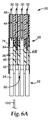
図6Aは、図5の線6A−6Aでのプローブブロックアセンブリ20の断面図であり、図6Bは接地プレート40に接触している弾力性接地ビーム74、76の拡大図である。同軸コネクタアセンブリ22の各同軸ケーブル24は、第1プローブ30の1つに接続される。第2プローブ32は接地プローブレセプタクル46に挿入され、図6A中、第2プローブ32に揃えられている同軸ケーブル24は実際は背景にあり、第2プローブ32の向こう側にある第1プローブ30に接続される。
6A is a cross-sectional view of
各第1プローブ30は絶縁体44によって接地プレート40から電気的に絶縁されており、同軸ケーブル24を介した信号伝送のために接触部60(図2)で電気的に接続されている。同軸コネクタ26の弾力性接地ビーム74、76は、接地プレート40と接触し、ブロック28に挿入される第2プローブ32を共通接地する。特に、弾力性接地ビーム74、76は、同軸コネクタ26が接地プレート40に挿入されたときに同軸コネクタ26に向かって内側に弾力的に屈曲し(これにより弾力性接地ビーム74、76の小さな部分だけがシールド体62を超えて延在する)、第2プローブ32は接地プローブレセプタクル46に押し嵌められ、これがブロック28内に押し嵌められる。このようにして、第2プローブ32のすべてが同じ接地電位を有し、接地パスは、ケーブルシールド54からシールド体62を通り、弾力性接地ビーム74、76を通って、接地プレート40のプレート84へ、接地プローブレセプタクル46へ、そして最終的に第2プローブ32へと至って形成される。
Each
インピーダンス制御は、接地プレート40に形成される開口部48の直径、第1プローブ30の直径、及び絶縁体44の有効誘電率を選択的に調整することによって提供される。一実施形態において、第1プローブ30、絶縁体44、及び接地プレート40に形成された開口部48によってもたらされる固有インピーダンスは、同軸コネクタアセンブリ22の固有インピーダンスと実質的に同じである。
Impedance control is provided by selectively adjusting the diameter of the
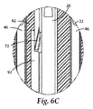
図6Cは、絶縁されたハウジング42と噛み合ったラッチ72の拡大図である。図6Cの断面図は、図6Bの図に直交しており、図6Aに示した領域6C付近のものである。ブロック28は、接地プレート40を絶縁されたハウジング42と噛み合わせることにより組み立てられる。同軸コネクタ26は、ラッチ72を絶縁されたハウジング42と嵌め合わせることによりブロック28(図1)内に挿入されて保持され、これにより、弾力性接地ビーム74、76(図6B)を接地プレート40(図6B)のプレート84(図6A)に接触させることができる。ツールスロット92により、ツール100(図6D)を挿入してラッチ92を係合離脱させることが可能になる。
FIG. 6C is an enlarged view of the
従来のプローブブロックアセンブリの既知のコネクタは、一般に、金属製ブロックの裏側に押し嵌められ、その金属製ブロックの表側に押し嵌められた信号プローブ(例えばスプリングプローブ)に接続される。時折、従来のプローブブロックアセンブリの使用中に、1本以上のプローブが破損することがある。この破損したプローブは、これまでは、スプリングプローブを表側から除去し、破損又は故障したコネクタをブロックから押し出し(例えばアーバープレスを用いて)てから、そのブロックに、破損していないコネクタ及びスプリングプローブを押し嵌めして戻すことにより交換していた。既知のコネクタ及びスプリングプローブの除去及び交換は、ブロックに対する磨耗を増加させる可能性があり、ブロックに適用された抗酸化性コーティング及び同様物を剥がす可能性があり、これらは、スプリングプローブとブロックとの間の電気的接触に望ましくない影響をもたらす。 Known connectors of conventional probe block assemblies are typically pressed into the back side of a metal block and connected to a signal probe (eg, a spring probe) that is pressed into the front side of the metal block. Occasionally, one or more probes may break during use of a conventional probe block assembly. Previously, the damaged probe was removed from the front side of the spring probe, and the damaged or failed connector was pushed out of the block (eg, using an arbor press) before the undamaged connector and spring probe. It was exchanged by pushing and fitting back. The removal and replacement of known connectors and spring probes can increase wear on the block and can remove the anti-oxidant coating and the like applied to the block, including the spring probe and the block. It has an undesirable effect on the electrical contact between.
一方、上述の同軸コネクタアセンブリ22は、例えばツール100を使って、ラッチ72を押し、同軸コネクタ26をブロック28から手で引っ張ることにより、ブロック28から取り出すことができる。この同軸コネクタアセンブリ22は、よって、整備技術者が現場で交換可能であり、コネクタをプローブアセンブリブロックからアーバープレスで押し出す際の費用を最小限に抑え、かつ、ブロックに対する磨耗を最小限に抑える。
On the other hand, the
同軸コネクタアセンブリ22は、幅広い有用な実施方法において、プローブブロックアセンブリの接地プローブを共通接地するよう構成された1つ以上の弾力性接地ビーム74、76を含み、これらのいくつかが図7〜9に示されている。
The
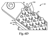
図6Dは、組み立てられたプローブブロックアセンブリ20の底面図である。一実施形態において、ツールスロット92は、シールド体62(図2)上のラッチ72を押し下げるためにツールスロット92に挿入されるツールを受容する寸法になされ、これにより、同軸コネクタアセンブリ22の除去及び現場での交換が可能になる。一実施形態において、ツール100は、ラッチ72(図6C)を押し下げてブロック28から同軸コネクタ26を取り出すために、絶縁されたハウジング42の方向からツールスロット92に挿入される。一実施形態において、ツール100はプラスチックで製造され、手で操作するための寸法にされた近位端と、ツールスロット92に挿入するための寸法にされた細い遠位端とを含む。ツール100の他の形態も許容可能である。ラッチ72を押し下げることによって同軸コネクタ26が絶縁されたハウジング42から開放され、同軸コネクタアセンブリ22全体をブロック28から素早く便利に取り出すことが可能になる。
FIG. 6D is a bottom view of the assembled
図7は、接地プレート40によって供給される、導電性ブロックに挿入される第2プローブ32を共通接地するために採用されるプローブブロックアセンブリ20の断面図である。同軸コネクタアセンブリ22は第1プローブ30と電気的に接続され、これは絶縁体44によって接地プレート40から電気的に絶縁されている。シールド体62には、弾力性接地ビーム74、76が含まれ、これは第2プローブ32を共通接地する方法で接地プレート40に接触している。特に、この構成で提供される接地パスは、シールド体62から弾力性接地ビーム74、76を介して、接地プレート40に入り、接地プレート40に押し嵌められる接地プローブレセプタクル46へ、更にはこの接地プローブレセプタクル46に押し嵌められる第2プローブ32へと延びる。
FIG. 7 is a cross-sectional view of the
図8は、接地プローブレセプタクル46と直接接触し、その接地プローブレセプタクル46内に保持される第2プローブ32を共通接地するよう構成された、同軸コネクタアセンブリ22の断面図を示す。例えば、一実施形態において、同軸コネクタアセンブリ22は、接地プローブレセプタクル46の間に挿入されて、第1プローブ30に電気的に接続され、弾力性接地ビーム74、76は、第2プローブ32を共通接地するためのモノリシックブロック110に挿入される接地プローブレセプタクル46と接触する。一実施形態において、モノリシックブロック110は非導電性のブロックである。一実施形態において、モノリシックブロック110は導電性のブロックである。
FIG. 8 shows a cross-sectional view of the
図9は、第2プローブ32に直接に共通接地された、同軸コネクタアセンブリ22の断面図を示す。第2プローブ32はモノリシックブロック120に押し嵌められ、同軸コネクタアセンブリ22は第2プローブ32の間に挿入されて、弾力性接地ビーム74、76が第2プローブ32と接触して共通接地できる方法で、第1プローブ30と電気的に接続する。一実施形態において、モノリシックブロック120は非導電性のブロックである。一実施形態において、モノリシックブロック120は導電性のブロックである。
FIG. 9 shows a cross-sectional view of the
上述の実施形態の少なくともいくつかは、導電性接地プレート40に接触することによって(図7)、又は接地プローブレセプタクル46に接触することによって(図8)、又は1本以上の第2プローブ32に直接接触することによって(図9)、ブロックに挿入される複数の接地プローブを共通接地するよう構成された弾力性かつ柔軟な接地ビームを有する同軸コネクタアセンブリ22を提供する。
At least some of the embodiments described above may contact the conductive ground plate 40 (FIG. 7), or contact the ground probe receptacle 46 (FIG. 8), or to one or more second probes 32. By direct contact (FIG. 9), a
図10は、別の実施形態によるプローブブロックアセンブリ150の断面図である。プローブブロックアセンブリ150は、第1プローブ30に電気的に接続され、ブロック140に挿入された複数の第2プローブ32を共通接地する、上述の同軸コネクタアセンブリ22と、絶縁体154によってブロック140から絶縁され、電源配線156に接続された、電源プローブ152とを含む。第1プローブ30は絶縁体44によってブロック140から絶縁され、同軸ケーブル24を介して信号を伝達する。第2プローブ32は接地プローブレセプタクル46に押し嵌められ、これが更にブロック140に押し嵌められて電気的に接触する。電源プローブ152は、プローブブロックアセンブリ150に連結された電子デバイス(図示せず)に、電源配線156を介して電力を送達するよう構成される。別の実施形態において、電源プローブ152は、ユーザ環境によって規定されるように、ユーティリティプローブ又はその他の好適なプローブに交換することができる。
FIG. 10 is a cross-sectional view of a
いくつかの実施形態には、第1プローブ30を受容するブロック140の開口部、第1プローブ30の直径、及び絶縁体44の有効誘電率を選択的に調整することによってもたらされるインピーダンス制御を備えて提供されるプローブブロックアセンブリ150が含まれる。
Some embodiments include impedance control provided by selectively adjusting the aperture of the
一実施形態において、電源プローブ152は絶縁体154によってブロック140から絶縁され、同軸コネクタアセンブリ22の1つに電気的に接続されて、これにより電力が同軸ケーブル24の中央導電体50を介して送達される(図2)。すなわち、一実施形態は、同軸コネクタアセンブリ22に伴う同軸ケーブルを介して電力を供給するオプションを提供する。
In one embodiment, the power probe 152 is isolated from the
いくつかの実施形態は、第1プローブと電気的に接続するよう構成され、プローブブロックアセンブリの1本以上の第2プローブを共通接地するよう構成された1つ以上の弾力性接地ビームを伴って提供される、同軸コネクタアセンブリを含むプローブブロックアセンブリを提供する。いくつかの実施形態は、プローブブロックアセンブリのコンポーネントについて、制御されたインピーダンス又はインピーダンス一致を提供する、便利かつ現場で交換可能なコネクタアセンブリを提供する。 Some embodiments include one or more resilient ground beams configured to electrically connect with the first probe and configured to commonly ground one or more second probes of the probe block assembly. Provided is a probe block assembly including a coaxial connector assembly. Some embodiments provide a convenient and field replaceable connector assembly that provides a controlled impedance or impedance match for the components of the probe block assembly.
本明細書において特定の実施形態が例示及び説明されてきたが、本発明の範囲から逸脱することなく、多様な代替及び/又は同等の実施態様が特定の実施形態と置き換えられ得ることは、当業者には明白であろう。本願は、本明細書で論じたプローブブロックアセンブリのいかなる改作又は変型をも包含することを意図したものである。したがって、本発明が請求項及びその同等物によってのみ限定されることを、意図するものである。 While specific embodiments have been illustrated and described herein, it is to be understood that various alternative and / or equivalent embodiments may be substituted for the specific embodiments without departing from the scope of the invention. It will be obvious to the contractor. This application is intended to cover any adaptations or variations of the probe block assemblies discussed herein. Therefore, it is intended that this invention be limited only by the claims and the equivalents thereof.
Claims (20)
該ブロック中に挿入された複数のプローブと電気的に導通するよう構成された同軸コネクタを末端とするケーブルと、を含むプローブブロックアセンブリであって、前記同軸コネクタが
前記ブロックの開口部に挿入可能でありかつ前記ブロックから絶縁された第1プローブに、分離可能に接続するよう構成された、コネクタ信号接触部と、
前記ブロックに挿入された1本以上の第2プローブを共通接地するよう構成された弾力性接地ビームと、を含む、プローブブロックアセンブリ。 Block,
A probe block assembly including a coaxial connector configured to be electrically conductive with a plurality of probes inserted into the block, the coaxial connector being insertable into the opening of the block And a connector signal contact configured to detachably connect to a first probe insulated from said block;
A resilient ground beam configured to commonly ground one or more second probes inserted into the block.
前記開口部に挿入され、前記ブロックから電気的に絶縁されており、少なくとも一本の接地プローブが前記ブロックの前記プローブ側から延在する、第1プローブと、
前記第1プローブとの電気的接続のために前記開口部内にある程度まで挿入可能であるコネクタを末端とする同軸ケーブルを含む同軸ケーブルアセンブリと、を含むプローブブロックアセンブリであって、前記コネクタが、前記ブロックと取り外し可能に連結したシールド体と、前記接地プローブを共通接地するよう構成された弾力性接地ビームと、前記第1プローブに接続するよう構成された信号接触部とを含む、プローブブロックアセンブリ。 A block defining an opening extending between the probe side and the cable side of the block;
A first probe inserted into the opening and electrically insulated from the block, wherein at least one ground probe extends from the probe side of the block;
A coaxial cable assembly including a coaxial cable terminated with a connector that is insertable to some extent into the opening for electrical connection with the first probe, wherein the connector comprises the connector A probe block assembly including a shield body removably coupled to the block, a resilient ground beam configured to commonly ground the ground probe, and a signal contact configured to connect to the first probe.
前記インピーダンス制御されたコネクタのインピーダンスは、前記インピーダンス制御されたブロック部分のインピーダンスに実質的に一致している、請求項11に記載のプローブブロックアセンブリ。 The block includes a conductive block, further comprising an impedance controlled block portion defined by the first probe electrically isolated from the conductive block by an insulator inserted into the opening; A connector including an impedance controlled connector inserted to some extent into the opening from the cable side of the conductive block;
The probe block assembly of claim 11, wherein the impedance of the impedance controlled connector substantially matches the impedance of the impedance controlled block portion.
前記導電性ブロック部分に連結されて、絶縁性ブロック部分を通過して延びるチャネルが、前記開口部、及び該開口部に挿入される前記絶縁体と揃っている、その絶縁性ブロック部分と、
前記チャネルに挿入可能であって、前記絶縁性ブロック部分と取り外し可能に連結しかつ前記第1プローブと電気的に接続するよう構成されており、前記接地プローブを共通接地するよう構成されている弾力性接地ビームを含む、シールドされた同軸コネクタと、を含む、プローブブロックアセンブリ。 Conductivity defining an opening, an insulator inserted into the opening, a first probe inserted into the insulator and retained within the opening, and a ground probe coupled to the conductive block portion Block part,
A channel connected to the conductive block portion and extending through the insulating block portion is aligned with the opening and the insulator inserted into the opening; and
A resilience configured to be removably coupled to the insulative block portion and electrically connected to the first probe, wherein the ground probe is commonly grounded, and is insertable into the channel. A probe block assembly including a shielded coaxial connector including a conductive ground beam.
Applications Claiming Priority (3)
| Application Number | Priority Date | Filing Date | Title |
|---|---|---|---|
| US12/206,565 US7740508B2 (en) | 2008-09-08 | 2008-09-08 | Probe block assembly |
| US12/206,565 | 2008-09-08 | ||
| PCT/US2009/055872 WO2010028136A2 (en) | 2008-09-08 | 2009-09-03 | Probe block assembly |
Publications (2)
| Publication Number | Publication Date |
|---|---|
| JP2012502277A true JP2012502277A (en) | 2012-01-26 |
| JP2012502277A5 JP2012502277A5 (en) | 2012-09-27 |
Family
ID=41797849
Family Applications (1)
| Application Number | Title | Priority Date | Filing Date |
|---|---|---|---|
| JP2011526195A Pending JP2012502277A (en) | 2008-09-08 | 2009-09-03 | Lobe block assembly |
Country Status (6)
| Country | Link |
|---|---|
| US (1) | US7740508B2 (en) |
| EP (1) | EP2340555A4 (en) |
| JP (1) | JP2012502277A (en) |
| KR (1) | KR20110060922A (en) |
| CN (1) | CN102197469A (en) |
| WO (1) | WO2010028136A2 (en) |
Cited By (2)
| Publication number | Priority date | Publication date | Assignee | Title |
|---|---|---|---|---|
| WO2014007077A1 (en) * | 2012-07-03 | 2014-01-09 | 株式会社オートネットワーク技術研究所 | Multi-pole connector |
| JP2020537161A (en) * | 2017-11-30 | 2020-12-17 | リーノ インダストリアル インコーポレイテッド | Inspection equipment |
Families Citing this family (31)
| Publication number | Priority date | Publication date | Assignee | Title |
|---|---|---|---|---|
| EP2197254B1 (en) * | 2008-12-09 | 2011-08-31 | Siemens Aktiengesellschaft | Electronics module for an assembly module |
| US7997933B2 (en) | 2009-08-10 | 2011-08-16 | 3M Innovative Properties Company | Electrical connector system |
| US7927144B2 (en) * | 2009-08-10 | 2011-04-19 | 3M Innovative Properties Company | Electrical connector with interlocking plates |
| US7850489B1 (en) | 2009-08-10 | 2010-12-14 | 3M Innovative Properties Company | Electrical connector system |
| US7909646B2 (en) * | 2009-08-10 | 2011-03-22 | 3M Innovative Properties Company | Electrical carrier assembly and system of electrical carrier assemblies |
| US8187035B2 (en) * | 2010-05-28 | 2012-05-29 | Tyco Electronics Corporation | Connector assembly |
| US8052470B1 (en) * | 2011-01-12 | 2011-11-08 | Cheng Uei Precision Industry Co., Ltd. | Probe connector |
| US8083548B1 (en) * | 2011-01-13 | 2011-12-27 | Cheng Uei Precision Industry Co., Ltd. | Probe connector |
| US8888531B2 (en) * | 2011-10-11 | 2014-11-18 | Tyco Electronics Corporation | Electrical connector and circuit board assembly including the same |
| JP5847663B2 (en) * | 2012-08-01 | 2016-01-27 | 日本電子材料株式会社 | Manufacturing method of probe card guide plate |
| WO2014132274A1 (en) * | 2013-02-27 | 2014-09-04 | Power-One Italy S.P.A. | Programming connector |
| CN104345184B (en) * | 2013-07-26 | 2019-03-01 | 苏州普源精电科技有限公司 | A kind of measuring instrument that multichannel obtains probe and pops one's head in multichannel acquisition |
| TWM482874U (en) * | 2014-04-01 | 2014-07-21 | Insert Entpr Co Ltd | RF pass through connector |
| CN104600443A (en) * | 2015-01-21 | 2015-05-06 | 谢博 | Grounding wire electrode |
| TWI704352B (en) * | 2015-03-13 | 2020-09-11 | 義大利商探針科技公司 | Contact probe for a testing head |
| KR101690622B1 (en) * | 2015-04-29 | 2016-12-28 | 주식회사 한라정밀엔지니어링 | Probe for testing LED and Contact device having it |
| DE102015109022B4 (en) * | 2015-06-08 | 2018-08-23 | Infineon Technologies Ag | Modular measuring device for testing of test pieces by means of interface elements |
| US9979112B2 (en) * | 2016-03-29 | 2018-05-22 | Aces Electronics Co., Ltd. | Press-type connector |
| US10283899B2 (en) * | 2016-10-10 | 2019-05-07 | Cisco Technology, Inc. | Cable header |
| KR101906575B1 (en) * | 2016-11-29 | 2018-10-11 | 리노공업주식회사 | Camera module test device |
| CN110945366B (en) * | 2017-07-28 | 2022-08-30 | 日本发条株式会社 | Contact probe and probe unit |
| CN109581005B (en) * | 2017-09-29 | 2021-01-22 | 中华精测科技股份有限公司 | Probe assembly and space conversion interface board thereof |
| TWI626453B (en) * | 2017-09-29 | 2018-06-11 | 中華精測科技股份有限公司 | Probe assembly and capacitive space transformer thereof |
| US10476196B2 (en) * | 2018-02-28 | 2019-11-12 | Ohio Associated Enterprises, Llc | Electrical connector with contacts holding spring-loaded pins |
| US10938139B2 (en) * | 2018-08-21 | 2021-03-02 | Te Connectivity Corporation | Electrical connector with retractable contacts |
| KR102546497B1 (en) * | 2018-09-13 | 2023-06-23 | 하르팅 일렉트릭 슈티프퉁 운트 코우. 카게 | Plug-in connector with ground terminal area |
| US11567102B2 (en) * | 2019-09-04 | 2023-01-31 | Chien Wen Chang | Auxiliary device for functional expansion and signal acquisition of testing system |
| CN112240947B (en) * | 2020-12-18 | 2021-04-30 | 苏州和林微纳科技股份有限公司 | Assembly method of ultrahigh frequency spring probe test assembly |
| US11835567B2 (en) * | 2020-12-18 | 2023-12-05 | Suzhou Uigreen Micro&Nano Technology Co. Ltd. | Method for assembling ultrahigh-frequency spring probe test assembly |
| CN116879586A (en) * | 2023-07-28 | 2023-10-13 | 上海捷策创电子科技有限公司 | Coaxial high-speed interface device for semiconductor test |
| CN116754814B (en) * | 2023-08-11 | 2023-10-24 | 杭州朗迅科技股份有限公司 | High-density probe card, preparation method and test method |
Family Cites Families (10)
| Publication number | Priority date | Publication date | Assignee | Title |
|---|---|---|---|---|
| US4734046A (en) | 1984-09-21 | 1988-03-29 | International Business Machines Corporation | Coaxial converter with resilient terminal |
| US5485140A (en) * | 1994-06-24 | 1996-01-16 | Bussin; George N. | Vehicle obstacle detector and alarm system |
| US6498506B1 (en) * | 2000-07-26 | 2002-12-24 | Gore Enterprise Holdings, Inc. | Spring probe assemblies |
| US6447328B1 (en) * | 2001-03-13 | 2002-09-10 | 3M Innovative Properties Company | Method and apparatus for retaining a spring probe |
| US6551126B1 (en) * | 2001-03-13 | 2003-04-22 | 3M Innovative Properties Company | High bandwidth probe assembly |
| US6902416B2 (en) * | 2002-08-29 | 2005-06-07 | 3M Innovative Properties Company | High density probe device |
| US6824427B1 (en) | 2003-05-13 | 2004-11-30 | 3M Innovative Properties Company | Coaxial probe interconnection system |
| US7015708B2 (en) | 2003-07-11 | 2006-03-21 | Gore Enterprise Holdings, Inc. | Method and apparatus for a high frequency, impedance controlled probing device with flexible ground contacts |
| US7371128B2 (en) | 2003-10-14 | 2008-05-13 | Precision Interconnect, Inc. | Cable terminal with air-enhanced contact pins |
| US7553187B2 (en) | 2006-01-31 | 2009-06-30 | 3M Innovative Properties Company | Electrical connector assembly |
-
2008
- 2008-09-08 US US12/206,565 patent/US7740508B2/en not_active Expired - Fee Related
-
2009
- 2009-09-03 EP EP09812211A patent/EP2340555A4/en not_active Withdrawn
- 2009-09-03 JP JP2011526195A patent/JP2012502277A/en active Pending
- 2009-09-03 WO PCT/US2009/055872 patent/WO2010028136A2/en active Application Filing
- 2009-09-03 CN CN2009801432688A patent/CN102197469A/en active Pending
- 2009-09-03 KR KR1020117007747A patent/KR20110060922A/en not_active Application Discontinuation
Cited By (6)
| Publication number | Priority date | Publication date | Assignee | Title |
|---|---|---|---|---|
| WO2014007077A1 (en) * | 2012-07-03 | 2014-01-09 | 株式会社オートネットワーク技術研究所 | Multi-pole connector |
| US9362692B2 (en) | 2012-07-03 | 2016-06-07 | Sumitomo Wiring Systems, Ltd. | Multipolar connector |
| JP2020537161A (en) * | 2017-11-30 | 2020-12-17 | リーノ インダストリアル インコーポレイテッド | Inspection equipment |
| JP7097452B2 (en) | 2017-11-30 | 2022-07-07 | リーノ インダストリアル インコーポレイテッド | Inspection equipment |
| US11391757B2 (en) | 2017-11-30 | 2022-07-19 | Leeno Industrial Inc. | Test device |
| US11726111B2 (en) | 2017-11-30 | 2023-08-15 | Leeno Industrial Inc. | Test device |
Also Published As
| Publication number | Publication date |
|---|---|
| EP2340555A2 (en) | 2011-07-06 |
| WO2010028136A3 (en) | 2010-06-03 |
| EP2340555A4 (en) | 2012-08-22 |
| WO2010028136A2 (en) | 2010-03-11 |
| CN102197469A (en) | 2011-09-21 |
| WO2010028136A8 (en) | 2010-07-22 |
| KR20110060922A (en) | 2011-06-08 |
| US7740508B2 (en) | 2010-06-22 |
| US20100062629A1 (en) | 2010-03-11 |
Similar Documents
| Publication | Publication Date | Title |
|---|---|---|
| JP2012502277A (en) | Lobe block assembly | |
| US9160151B2 (en) | Controlled-impedance cable termination using compliant interconnect elements | |
| JP3848300B2 (en) | connector | |
| US7015708B2 (en) | Method and apparatus for a high frequency, impedance controlled probing device with flexible ground contacts | |
| JP4745130B2 (en) | Differential measurement probe | |
| US7654847B2 (en) | Probe having a field-replaceable tip | |
| JP2012502277A5 (en) | ||
| KR100958489B1 (en) | Pin connector | |
| JP2005537481A (en) | High density probe device | |
| USRE47459E1 (en) | Controlled-impedance cable termination using compliant interconnect elements | |
| JPH0227795B2 (en) | ||
| EP1115177A3 (en) | Electrical plug connectors | |
| CN112020654B (en) | test device | |
| USRE46958E1 (en) | Controlled-impedance cable termination using compliant interconnect elements | |
| US20220045450A1 (en) | Connector Receptacle | |
| EP3158611B1 (en) | Connectors | |
| KR20200054325A (en) | Printed circuit board connector with shielding elements | |
| WO2016072986A1 (en) | Controlled-impedance cable termination using compliant interconnect elements | |
| CN218938344U (en) | Connector for inspection and inspection unit | |
| US2434211A (en) | Electrical connector | |
| EP0849835A3 (en) | Electrical connectors and connecting parts therefor | |
| WO2004109308A1 (en) | Device interface unit | |
| KR20160072862A (en) | Coixial connecter of radio frequency | |
| JP2006040905A (en) | Connector | |
| CN105846204A (en) | Electric connector |
Legal Events
| Date | Code | Title | Description |
|---|---|---|---|
| A521 | Request for written amendment filed |
Free format text: JAPANESE INTERMEDIATE CODE: A523 Effective date: 20120810 |
|
| A621 | Written request for application examination |
Free format text: JAPANESE INTERMEDIATE CODE: A621 Effective date: 20120810 |
|
| A977 | Report on retrieval |
Free format text: JAPANESE INTERMEDIATE CODE: A971007 Effective date: 20130626 |
|
| A131 | Notification of reasons for refusal |
Free format text: JAPANESE INTERMEDIATE CODE: A131 Effective date: 20130702 |
|
| A02 | Decision of refusal |
Free format text: JAPANESE INTERMEDIATE CODE: A02 Effective date: 20131126 |