JP2012502245A - Method for controlling the flow of refrigerant to the evaporator - Google Patents
Method for controlling the flow of refrigerant to the evaporator Download PDFInfo
- Publication number
- JP2012502245A JP2012502245A JP2011525406A JP2011525406A JP2012502245A JP 2012502245 A JP2012502245 A JP 2012502245A JP 2011525406 A JP2011525406 A JP 2011525406A JP 2011525406 A JP2011525406 A JP 2011525406A JP 2012502245 A JP2012502245 A JP 2012502245A
- Authority
- JP
- Japan
- Prior art keywords
- evaporator
- opening
- refrigerant
- expansion valve
- superheat value
- Prior art date
- Legal status (The legal status is an assumption and is not a legal conclusion. Google has not performed a legal analysis and makes no representation as to the accuracy of the status listed.)
- Pending
Links
- 239000003507 refrigerant Substances 0.000 title claims abstract description 106
- 238000000034 method Methods 0.000 title claims abstract description 36
- 238000001816 cooling Methods 0.000 claims abstract description 28
- 230000003247 decreasing effect Effects 0.000 claims abstract description 19
- 238000001035 drying Methods 0.000 claims abstract description 7
- 230000007423 decrease Effects 0.000 claims description 16
- 238000012544 monitoring process Methods 0.000 claims description 6
- 239000007791 liquid phase Substances 0.000 abstract description 22
- 239000012071 phase Substances 0.000 description 12
- 239000007788 liquid Substances 0.000 description 10
- 239000012530 fluid Substances 0.000 description 3
- 230000003111 delayed effect Effects 0.000 description 2
- 238000001704 evaporation Methods 0.000 description 2
- 238000012546 transfer Methods 0.000 description 2
- 238000009835 boiling Methods 0.000 description 1
- 239000002826 coolant Substances 0.000 description 1
- 230000000694 effects Effects 0.000 description 1
- 230000008020 evaporation Effects 0.000 description 1
- 238000004519 manufacturing process Methods 0.000 description 1
- 238000005259 measurement Methods 0.000 description 1
- 238000013021 overheating Methods 0.000 description 1
Images


Classifications
-
- F—MECHANICAL ENGINEERING; LIGHTING; HEATING; WEAPONS; BLASTING
- F25—REFRIGERATION OR COOLING; COMBINED HEATING AND REFRIGERATION SYSTEMS; HEAT PUMP SYSTEMS; MANUFACTURE OR STORAGE OF ICE; LIQUEFACTION SOLIDIFICATION OF GASES
- F25B—REFRIGERATION MACHINES, PLANTS OR SYSTEMS; COMBINED HEATING AND REFRIGERATION SYSTEMS; HEAT PUMP SYSTEMS
- F25B41/00—Fluid-circulation arrangements
- F25B41/30—Expansion means; Dispositions thereof
- F25B41/31—Expansion valves
- F25B41/34—Expansion valves with the valve member being actuated by electric means, e.g. by piezoelectric actuators
- F25B41/345—Expansion valves with the valve member being actuated by electric means, e.g. by piezoelectric actuators by solenoids
- F25B41/347—Expansion valves with the valve member being actuated by electric means, e.g. by piezoelectric actuators by solenoids with the valve member being opened and closed cyclically, e.g. with pulse width modulation
-
- F—MECHANICAL ENGINEERING; LIGHTING; HEATING; WEAPONS; BLASTING
- F25—REFRIGERATION OR COOLING; COMBINED HEATING AND REFRIGERATION SYSTEMS; HEAT PUMP SYSTEMS; MANUFACTURE OR STORAGE OF ICE; LIQUEFACTION SOLIDIFICATION OF GASES
- F25B—REFRIGERATION MACHINES, PLANTS OR SYSTEMS; COMBINED HEATING AND REFRIGERATION SYSTEMS; HEAT PUMP SYSTEMS
- F25B2600/00—Control issues
- F25B2600/21—Refrigerant outlet evaporator temperature
-
- F—MECHANICAL ENGINEERING; LIGHTING; HEATING; WEAPONS; BLASTING
- F25—REFRIGERATION OR COOLING; COMBINED HEATING AND REFRIGERATION SYSTEMS; HEAT PUMP SYSTEMS; MANUFACTURE OR STORAGE OF ICE; LIQUEFACTION SOLIDIFICATION OF GASES
- F25B—REFRIGERATION MACHINES, PLANTS OR SYSTEMS; COMBINED HEATING AND REFRIGERATION SYSTEMS; HEAT PUMP SYSTEMS
- F25B2600/00—Control issues
- F25B2600/25—Control of valves
- F25B2600/2521—On-off valves controlled by pulse signals
-
- Y—GENERAL TAGGING OF NEW TECHNOLOGICAL DEVELOPMENTS; GENERAL TAGGING OF CROSS-SECTIONAL TECHNOLOGIES SPANNING OVER SEVERAL SECTIONS OF THE IPC; TECHNICAL SUBJECTS COVERED BY FORMER USPC CROSS-REFERENCE ART COLLECTIONS [XRACs] AND DIGESTS
- Y02—TECHNOLOGIES OR APPLICATIONS FOR MITIGATION OR ADAPTATION AGAINST CLIMATE CHANGE
- Y02B—CLIMATE CHANGE MITIGATION TECHNOLOGIES RELATED TO BUILDINGS, e.g. HOUSING, HOUSE APPLIANCES OR RELATED END-USER APPLICATIONS
- Y02B30/00—Energy efficient heating, ventilation or air conditioning [HVAC]
- Y02B30/70—Efficient control or regulation technologies, e.g. for control of refrigerant flow, motor or heating
Abstract
冷却システム内に配置される蒸発器(1)への冷媒の流れを制御するための方法が示されている。冷却システムは、膨張弁(12)及び圧縮器を含み、該膨張弁(12)、蒸発器(1)、及び圧縮器は、冷媒流を有する冷媒通路内に配置される。該方法は、膨張弁(12)の開度を増加させて、これにより蒸発器(1)の乾燥領域(3)を実質的に排除するように蒸発器(1)への冷媒の流れを十分に増加させ、時間が経過した後、膨張弁(12)の開度を減少させ、更に膨張弁(12)の開度を増加及び減少させる段階を繰り返す段階を含む。このようにして、膨張弁(12)の開度は、「パルス状」となる。これは、蒸発器(1)を出る冷媒の過熱度値を、ゼロレベルと、低いが、正のレベルとの間で「切り換る」ことを可能とする。これにより、蒸発器(1)を出る冷媒の平均過熱度値は減少され、蒸発器(1)の冷媒能力は、一層効率的に利用される。同時に、蒸発器(1)を通過することが可能な液相冷媒の量は、圧縮器への損傷を防ぐのに十分低い量を維持することが確実なものとなる。 A method for controlling the flow of refrigerant to the evaporator (1) located in the cooling system is shown. The cooling system includes an expansion valve (12) and a compressor, the expansion valve (12), the evaporator (1), and the compressor being disposed in a refrigerant passage having a refrigerant flow. The method increases the degree of refrigerant flow to the evaporator (1) to increase the opening of the expansion valve (12), thereby substantially eliminating the drying region (3) of the evaporator (1). And after the lapse of time, the step of decreasing the opening of the expansion valve (12) and further increasing and decreasing the opening of the expansion valve (12) are included. In this way, the opening degree of the expansion valve (12) is “pulsed”. This allows the superheat value of the refrigerant leaving the evaporator (1) to be “switched” between a zero level and a low but positive level. Thereby, the average superheat value of the refrigerant leaving the evaporator (1) is reduced and the refrigerant capacity of the evaporator (1) is utilized more efficiently. At the same time, it is ensured that the amount of liquid phase refrigerant that can pass through the evaporator (1) is kept low enough to prevent damage to the compressor.
Description
本発明は、冷却システム内に配置された蒸発器への冷媒の流れを制御するための方法に関する。本発明の方法は、蒸発器の冷却能力を、従来の技術方法を使用する場合より効率的に利用することを確実にするような方法で、冷却システムを制御することができる。 The present invention relates to a method for controlling the flow of refrigerant to an evaporator located in a cooling system. The method of the present invention can control the cooling system in a manner that ensures that the cooling capacity of the evaporator is utilized more efficiently than when using prior art methods.
冷却システムは、多くの場合、膨張弁の開度を調整し、及び/又は膨張弁を開閉して蒸発器に供給される液相冷媒の量を制御することにより、作動する。蒸発器に供給される液相冷媒のすべてが蒸発器を出る前に蒸発するように、かつ、混合相の冷媒が蒸発器の出口に存在するか又は出口の直前に存在するように、膨張弁を制御することが望ましい。液相冷媒が蒸発器を出ることができるようにされている場合には、この液相冷媒が圧縮器に到達する危険性があり、これは、場合によっては圧縮器を損傷することになる。一方、液相冷媒が、蒸発器の最初の部分を通過する間に蒸発するような場合には、蒸発器の冷却能力が十分に利用されない。 Cooling systems often operate by adjusting the opening of the expansion valve and / or opening and closing the expansion valve to control the amount of liquid phase refrigerant supplied to the evaporator. An expansion valve so that all of the liquid phase refrigerant supplied to the evaporator evaporates before exiting the evaporator, and so that mixed phase refrigerant is present at or just before the outlet of the evaporator. It is desirable to control. If liquid phase refrigerant is allowed to exit the evaporator, there is a risk that this liquid phase refrigerant will reach the compressor, which in some cases will damage the compressor. On the other hand, when the liquid-phase refrigerant evaporates while passing through the first part of the evaporator, the cooling capacity of the evaporator is not fully utilized.
冷媒の過熱度は、上記した状況が得られているか、いないかという情報を提供する。過熱度は、通常は、流体の実際の温度と、流体の沸点との差と定義される。したがって、過熱度は、流体の温度並びに圧力に依存する。このように、過熱度は、膨張弁の開度を制御するために適切なパラメータである。冷媒は、低いが、正の過熱度を有することが、通常は望ましい。この場合には、上記した状況、すなわち蒸発器の冷却能力が最大限まで可能な範囲で利用され、蒸発器を通過する液相冷媒によって圧縮器へ損傷を与える危険性が最小となる状況が得られる。 The degree of superheat of the refrigerant provides information on whether or not the above situation is obtained. Superheat is usually defined as the difference between the actual temperature of the fluid and the boiling point of the fluid. Accordingly, the degree of superheat depends on the temperature and pressure of the fluid. Thus, the degree of superheat is an appropriate parameter for controlling the opening degree of the expansion valve. It is usually desirable that the refrigerant has a low but positive degree of superheat. In this case, the situation described above, that is, the situation where the cooling capacity of the evaporator is used to the maximum extent possible and the risk of damaging the compressor by the liquid-phase refrigerant passing through the evaporator is minimized. It is done.
このように、蒸発器を出る冷媒の過熱度値は、理想的にはゼロとするべきである。しかしながら、過熱度値がゼロの場合に、蒸発器が最適な方法で作動しているか、すなわち液相冷媒が、蒸発器内で正確に蒸発しているか、或いは大量の液相冷媒が蒸発器内を通過しているかどうかを知ることが不可能である。したがって、従来の冷却システムのほとんどの場合において、膨張弁の開度が、正の過熱度、例えば凡そ5−10Kに維持されるような方法で制御されている。これにより、確実に液相冷媒が蒸発器内を通過できないようにする。しかしながら、これは、蒸発器の冷却能力が十分に利用されていない結果をもたらす。 Thus, the superheat value of the refrigerant leaving the evaporator should ideally be zero. However, if the superheat value is zero, the evaporator is operating in an optimal manner, i.e. the liquid refrigerant is evaporating correctly in the evaporator, or a large amount of liquid refrigerant is in the evaporator. It is impossible to know if you are passing through. Therefore, in most cases of conventional cooling systems, the opening of the expansion valve is controlled in such a way as to maintain a positive degree of superheat, for example approximately 5-10K. This ensures that the liquid phase refrigerant cannot pass through the evaporator. However, this has the result that the cooling capacity of the evaporator is not fully utilized.
A.TambovtsevとH.Quackによる「COP Improvements by Transfer of the Superheating into the Internal Heat Exchanger」ICR07−B2−1406には、冷却システム及び冷却システムの制御方法が記載されている。冷却システムには、蒸発器を通過することができる液相冷媒が、圧縮器に到達する前に蒸発することを確実にする付加的内部熱交換器が設けられている。これにより、わずかに湿潤した出口流が得られ、蒸発器の熱転移領域全体を、冷媒蒸発のために使用できるようになり、蒸発器の効率が改善される。しかしながら、この文献に提案されている解決策は、付加的な熱交換器が必要であることが欠点であり、それは、冷却システムを製造する費用が増加し、かつシステムが複雑になるという理由からである。 A. Tamvovtsev and H.C. Quack “COP Improvements by Transfer of the Superheating into the Internal Heat Exchanger” ICR07-B2-1406 describes a cooling system and a cooling system control method. The cooling system is provided with an additional internal heat exchanger that ensures that the liquid refrigerant that can pass through the evaporator evaporates before reaching the compressor. This results in a slightly moist outlet flow, allowing the entire heat transfer area of the evaporator to be used for refrigerant evaporation and improving the efficiency of the evaporator. However, the solution proposed in this document is disadvantageous in that it requires an additional heat exchanger because of the increased cost of manufacturing the cooling system and the complexity of the system. It is.
蒸発器の冷却能力が、従来技術の制御方法の場合よりも大きい範囲で利用されることを可能にする、蒸発器への冷媒の流れを制御する方法を提供することが、本発明の目的である。 It is an object of the present invention to provide a method for controlling the flow of refrigerant to the evaporator that allows the cooling capacity of the evaporator to be utilized in a greater range than in the case of prior art control methods. is there.
圧縮器を損傷させる危険性を無くして、蒸発器の冷却能力の利用を増加させる、蒸発器への冷媒の流れを制御する方法を提供することが、本発明の目的である。 It is an object of the present invention to provide a method for controlling the flow of refrigerant to the evaporator that eliminates the risk of damaging the compressor and increases the utilization of the cooling capacity of the evaporator.
冷却システムの部品数及び複雑さを減少することができる、蒸発器への冷媒の流れを制御する方法を提供することが、本発明の目的である。 It is an object of the present invention to provide a method of controlling the flow of refrigerant to the evaporator that can reduce the number and complexity of the cooling system.
本発明によると、上記及び他の目的は、膨張弁及び圧縮器を含み、該膨張弁、蒸発器、及び圧縮器が、冷媒流を有する冷媒流路内に配置された構成の冷却システム内に配置された蒸発器への冷媒の流れを制御するための方法であって、
膨張弁の開度を増加させ、これにより蒸発器の乾燥領域を実質的に十分に排除するように、蒸発器への冷媒の流れを増加させ、
ある時間が経過した後に、膨張弁の開度を減少させ、
膨張弁の開度を増加させる段階及び減少させる段階を繰り返す、
段階を含む方法を提供することにより実現される。
According to the present invention, the above and other objects include an expansion valve and a compressor, wherein the expansion valve, the evaporator, and the compressor are disposed in a cooling system configured to be disposed in a refrigerant flow path having a refrigerant flow. A method for controlling the flow of refrigerant to a disposed evaporator, comprising:
Increase the flow of refrigerant to the evaporator so as to increase the opening of the expansion valve, thereby substantially eliminating the drying area of the evaporator,
After a certain period of time, reduce the opening of the expansion valve,
Repeat the steps of increasing and decreasing the opening of the expansion valve,
This is accomplished by providing a method that includes steps.
冷媒は、例えば次のような冷媒のグループ:HFC、HCFC、CFC又はHCの1つから選択された、適当な種類の冷媒のいずれかとすることができる。別の適当な冷媒は、CO2である。 The refrigerant can be any suitable type of refrigerant selected, for example, from one of the following refrigerant groups: HFC, HCFC, CFC or HC. Another suitable refrigerant is CO2.
本発明の方法によると、膨張弁の開度は、最初は増加させられる。膨張弁の開度が増加すると、蒸発器に供給される冷媒の流れが増加する。開度は、蒸発器への冷媒の流れが、蒸発器の乾燥領域を実質的に十分に排除するまで増加することを十分に確実なものとする量だけ及び時間間隔だけ、増加させられる。これは、液相/混合相冷媒と気相冷媒との間の境界が、蒸発器の出口まで移動するか、又は出口を越えた位置にある状態、すなわち蒸発器内の冷媒が、液相状態であるか又は液相と気相の混合相冷媒であるという意味に解釈すべきである。これにより、蒸発器を出る冷媒の過熱度値はゼロになり、液相冷媒が蒸発器を通過することが、最も起こり得る状態になる。 According to the method of the present invention, the opening of the expansion valve is initially increased. As the opening of the expansion valve increases, the flow of refrigerant supplied to the evaporator increases. The opening is increased by an amount and time interval that sufficiently ensures that the flow of refrigerant to the evaporator will increase until it substantially eliminates the drying area of the evaporator. This is because the boundary between the liquid phase / mixed phase refrigerant and the gas phase refrigerant moves to the outlet of the evaporator or is located beyond the outlet, that is, the refrigerant in the evaporator is in the liquid phase state. Or a mixed phase refrigerant of liquid and gas phase. As a result, the superheat value of the refrigerant exiting the evaporator becomes zero, and it is most likely that liquid phase refrigerant will pass through the evaporator.
ある程度の時間が経過した後、膨張弁の開度は、膨張弁の開度を増加させる段階を遂行する前の膨張弁の開度に対応する開度にまで減少させることが好ましい。それによって、膨張弁の開度は短期間増加し、次に冷却システムを制御するために使用される制御計画によって指示されるレベルに戻される。これは、蒸発器への冷媒の流れを、十分に蒸発器の乾燥領域を確立するように減少させること、すなわち液相冷媒に蒸発器内を通過させないことによる結果である。これにより、蒸発器を出る冷媒の過熱度値は、低いが、正の値にまで増加する。 After a certain amount of time has passed, it is preferable to reduce the opening of the expansion valve to an opening corresponding to the opening of the expansion valve before performing the step of increasing the opening of the expansion valve. Thereby, the opening of the expansion valve is increased for a short period of time and then returned to the level indicated by the control plan used to control the cooling system. This is a result of reducing the flow of refrigerant to the evaporator so as to sufficiently establish the drying region of the evaporator, i.e. not allowing liquid phase refrigerant to pass through the evaporator. This increases the superheat value of the refrigerant exiting the evaporator to a low but positive value.
開度を増加及び減少させる段階は、複数回繰り返されることが好ましい。これにより膨張弁の開度は、「パルス状」となる。膨張弁の「パルス状」開度は、蒸発器を出る冷媒の過熱度値を、ゼロと、低いが正の値との間で「切り換る」ことを可能にする。過熱度値は、周期的にゼロレベルにまで減少されるので、過熱度値が一定で、低い、正のレベルを維持するような状況と比較して、蒸発器を出る冷媒の平均値は減少する。これにより、蒸発器の冷却能力は一層効率的に利用され、すなわち、冷却システムは、より効率的方法で作動されることとなる。同時に、膨張弁の開度が再び減少する前の短い間に、過熱度値をゼロレベルで維持させることができるので、少量の液相冷媒だけが蒸発器を通過できるようになり、これにより過熱度値を正の値に増加させることを確実なものとする。したがって、液相冷媒が蒸発器内を通過することによる圧縮器への損傷を引き起こす危険性は排除されるか、又は少なくとも大幅に減少される。 The step of increasing and decreasing the opening is preferably repeated a plurality of times. As a result, the opening of the expansion valve becomes “pulsated”. The “pulsed” opening of the expansion valve allows the superheat value of the refrigerant exiting the evaporator to “switch” between zero and a low but positive value. The superheat value is periodically reduced to zero level, so the average value of the refrigerant leaving the evaporator is reduced compared to the situation where the superheat value is constant, maintaining a low, positive level. To do. This allows the cooling capacity of the evaporator to be utilized more efficiently, i.e. the cooling system is operated in a more efficient manner. At the same time, the superheat value can be maintained at a zero level for a short time before the expansion valve opening decreases again, so that only a small amount of liquid refrigerant can pass through the evaporator, thereby overheating. Ensure that the degree value is increased to a positive value. Thus, the risk of causing damage to the compressor due to liquid phase refrigerant passing through the evaporator is eliminated or at least greatly reduced.
冷媒の流れが、膨張弁の開度が増加する前の冷媒の流れより5%−15%、例えば7%−12%、例えばおよそ10%増加するような形態で、膨張弁の開度を増加させることができる。 Increase the opening of the expansion valve in such a way that the flow of the refrigerant increases by 5% -15%, for example 7% -12%, for example about 10%, than the flow of the refrigerant before the expansion valve opens. Can be made.
膨張弁の開度を増加及び減少させる段階は、実質的に規則的間隔で繰り返すことができる。本実施形態によると、膨張弁の開度、及び結果的に蒸発器を出る冷媒の過熱度値は、実質的に一定周期の「パルス状になる」。代替的なものとしては、この期間は、例えば、冷却システムの様々な作動条件に応じて変化するようにすることができる。 The steps of increasing and decreasing the opening of the expansion valve can be repeated at substantially regular intervals. According to this embodiment, the opening degree of the expansion valve and, as a result, the superheat value of the refrigerant exiting the evaporator is “pulsated” with a substantially constant period. Alternatively, this period can vary depending on various operating conditions of the cooling system, for example.
代替的に、又は追加的に、膨張弁の開度が減少する前の経過時間は、実質的に一定の長さを有するものとすることができる。本実施形態によると、膨張弁の開度を増加させた状態に維持できる時間間隔は、実質的に一定であり、したがって限られた時間である。その結果、蒸発器を出る冷媒の過熱度値は、限られた時間だけゼロレベルであり、蒸発器を通過することが可能な液相冷媒の総量は、圧縮器を損傷させない程度の量に制限される。膨張弁の開度を増加させる段階が繰り返される前の経過時間は、実質的に一定の長さを有するものとすることができ、この場合には、開度を増加及び減少させる段階は、上記したように、実質的に一定の間隔で繰り返される。しかしながら、膨張弁の開度を増加させる段階の前の経過時間は、代替的に、長さを変化させることができる。 Alternatively or additionally, the elapsed time before the expansion valve opening is reduced may have a substantially constant length. According to the present embodiment, the time interval that can be maintained in the state in which the opening degree of the expansion valve is increased is substantially constant, and thus is a limited time. As a result, the superheat value of the refrigerant leaving the evaporator is at a zero level for a limited time, and the total amount of liquid phase refrigerant that can pass through the evaporator is limited to an amount that does not damage the compressor. Is done. The elapsed time before the step of increasing the opening of the expansion valve is repeated may have a substantially constant length, in which case the steps of increasing and decreasing the opening are as described above. As described above, it is repeated at substantially constant intervals. However, the elapsed time before the stage of increasing the opening of the expansion valve can alternatively vary in length.
代替的なものとして、膨張弁の開度が減少する前の経過時間は、長さを変化させることができ、この変化する長さは、冷媒の過熱度値の測定値を基に定められる。本実施形態によると、蒸発器を出る冷媒の過熱度値は、モニターされることが好ましい。上記したように、膨張弁の開度が増加した後、蒸発器を出る冷媒の過熱度値はゼロレベルにまで減少する。これが、過熱度値をモニターするために使用されるセンサーにより検知されると、冷媒をしばらくの間ゼロレベルに維持させるために、場合によっては一定の時間間隔を経過させた後、膨張弁の開度を前の開度にまで減少させる。膨張弁の開度を増加させる段階が繰り返される前に経過する時間は、上記したように、一定にするか、又は変化させることができる。この時間が変化するようにする場合には、その時間は、同様に、冷媒の過熱度値の測定値を基本にして定めることができる。この場合には、過熱度値が正の値にまで増加したことが検知された時、膨張弁の開度が増加する、という利点を得ることができる。これにより、過熱度値は、ほとんどの時間でゼロレベルを維持することが確実にされ、一方で、限定された量の液相冷媒だけが、蒸発器を通過できるようにすることが確実になる。 As an alternative, the elapsed time before the opening of the expansion valve decreases can be changed in length, which is determined based on the measured value of the superheat value of the refrigerant. According to this embodiment, the superheat value of the refrigerant leaving the evaporator is preferably monitored. As described above, after the opening of the expansion valve increases, the superheat value of the refrigerant exiting the evaporator decreases to zero level. If this is detected by a sensor used to monitor the superheat value, the expansion valve may be opened after a certain time interval, in order to maintain the refrigerant at zero level for some time. Decrease degree to previous opening. The time that elapses before the step of increasing the opening of the expansion valve is repeated can be constant or varied as described above. When this time is changed, the time can be similarly determined based on the measured value of the superheat value of the refrigerant. In this case, it is possible to obtain an advantage that the opening degree of the expansion valve increases when it is detected that the superheat value has increased to a positive value. This ensures that the superheat value remains at zero level for most of the time, while ensuring that only a limited amount of liquid phase refrigerant can pass through the evaporator. .
この方法は、冷媒の過熱度値をモニターする段階を更に含むことができる。これは、蒸発器の出口に、又は出口の近くに過熱度センサーを配置することにより行うことができる。過熱度センサーは、蒸発器を出る冷媒の温度及び圧力を別個に測定する形式のものとするか、或いは過熱度を直接測定する形式のものとすることができる。 The method may further include monitoring the refrigerant superheat value. This can be done by placing a superheat sensor at or near the outlet of the evaporator. The superheat sensor can be of the type that separately measures the temperature and pressure of the refrigerant exiting the evaporator, or it can be of the type that directly measures the superheat.
この場合において、この方法は、冷媒の過熱度値をモニターする段階で、開度が減少した後に過熱度値がゼロレベルに留まっていることが示された場合に、膨張弁の開度を増加させる段階の開始を遅らせる段階を更に含むことができる。本実施形態によると、増加及び減少する段階の繰り返しの「パルス状」期間、及び/又は増加する段階を繰り返す段階の前の経過時間は、通常の状態では実質的に一定にすることが有利である。しかしながら、過熱度値が、膨張弁の開度の減少に対応して正の値にまで増加しないことを過熱度値の測定値が示す場合には、このことは、平均過熱度値が低過ぎ、したがって過度の量の液相冷媒が蒸発器を通過できるようになるという危険性があることを示している。これを防ぐために、膨張弁の開度は、長い間、例えば増加/減少サイクルの付加的期間の間、低い値に維持されるようにする。過熱度値が、依然としてゼロレベルを維持する場合には、膨張弁の開度を増加する段階の開始を更に遅らせるか、又は膨張弁の開度を減少させることができる。 In this case, this method increases the opening of the expansion valve when it is shown that the superheat value stays at zero level after the opening is reduced in the stage of monitoring the superheat value of the refrigerant. The method may further include delaying the start of the causing step. According to this embodiment, it is advantageous that the “pulsed” period of the increasing and decreasing steps and / or the elapsed time before the increasing steps are substantially constant under normal conditions. is there. However, if the superheat value measurement indicates that the superheat value does not increase to a positive value in response to a decrease in the opening of the expansion valve, this means that the average superheat value is too low. Thus, there is a danger that an excessive amount of liquid refrigerant may be allowed to pass through the evaporator. In order to prevent this, the opening of the expansion valve is kept low for a long time, for example for an additional period of an increase / decrease cycle. If the superheat value still remains at zero level, the start of the step of increasing the expansion valve opening can be further delayed or the expansion valve opening can be decreased.
このように、この方法は、冷媒の過熱度値をモニターする段階で、開度を減少させた後も過熱度値がゼロレベルを維持していることが示される場合には、開度を付加的な量だけ減少させる段階を更に含むことができる。 Thus, this method adds the opening when the superheat value is maintained at the zero level even after the opening degree is reduced at the stage of monitoring the superheat value of the refrigerant. The method may further include the step of reducing by an appropriate amount.
蒸発器を出る冷媒の過熱度値がモニターされる場合には、この方法は、次のような意味での「追跡機能」を含むものとすることができる。過熱度値は、最初は比較的高い値であって、膨張弁の開度を少量だけ増加させることは、過熱度値がゼロレベルに到達できるようにするのには十分ではない。したがって、時間か経過した後に、開度を減少させる代りに、開度を少量だけ再び増加させる。モニターされた過熱度値が、蒸発器を出る冷媒の過熱度値がゼロレベルに到達したことを示すまで、これが繰り返される。次にこの方法は、上記したように、すなわち、膨張弁の開度が「パルス状となる」ように遂行される。膨張弁の開度を減少させた後、蒸発器を出る冷媒の過熱度値がゼロレベルで維持されていることが検知されるまで、これは続けられる。次に、膨張弁の開度を増加させる段階の開始を遅くするか、又は上記したように、膨張弁の開度を増加させる。 If the superheat value of the refrigerant exiting the evaporator is monitored, the method can include a “tracking function” in the following sense. The superheat value is initially relatively high, and increasing the opening of the expansion valve by a small amount is not sufficient to allow the superheat value to reach zero level. Therefore, after the time has elapsed, instead of decreasing the opening, the opening is increased again by a small amount. This is repeated until the superheat value monitored indicates that the superheat value of the refrigerant exiting the evaporator has reached a zero level. Next, this method is performed as described above, that is, so that the opening of the expansion valve is “pulsated”. After decreasing the opening of the expansion valve, this continues until it is detected that the superheat value of the refrigerant exiting the evaporator is maintained at zero level. Next, the start of the step of increasing the opening of the expansion valve is delayed or, as described above, the opening of the expansion valve is increased.
代替的に又は追加的に、この方法は、蒸発器を出る冷媒の過熱度値をモニターし、過熱度値が増加しているか又は減少しているかを判断するようにすることができる。モニターした過熱度値により、過熱度値が「非常に高い」こと、すなわち膨張弁の開度を増加したがゼロレベルにまだ到達していないが、過熱度値は減少しつつあることが示される場合には、現在のレベルに膨張弁の開度を維持すること、又は上記したように、膨張弁の開度を減少させて「パルス状にする」ことを決定することができる。これは、過熱度値の減少によって、過熱度値が「右側軌道上にある」ことが示されるからである。このシステムは、開度の増加が、幾分かの遅れを伴って過熱度値の減少に反映されるという意味で、ある程度の「慣性」を含むものである。したがって、上記した方法は、過剰な量の液相冷媒が蒸発器を通過できるようにする程度まで過熱度値が減少することを妨げる。 Alternatively or additionally, the method can monitor the superheat value of the refrigerant exiting the evaporator to determine whether the superheat value is increasing or decreasing. The superheat value monitored indicates that the superheat value is “very high”, ie, the expansion valve opening has been increased but has not yet reached the zero level, but the superheat value is decreasing. In some cases, it can be determined to maintain the opening of the expansion valve at the current level or to “pulse” the opening of the expansion valve as described above. This is because the decrease in superheat value indicates that the superheat value is “on the right orbit”. This system includes a certain amount of “inertia” in the sense that an increase in opening is reflected in a decrease in superheat value with some delay. Thus, the method described above prevents the superheat value from decreasing to an extent that allows an excessive amount of liquid refrigerant to pass through the evaporator.
膨張弁の開度を増加及び減少させる段階は、ヒステリシス制御計画における重畳として遂行することができる。本実施形態によると、膨張弁の「基本」の開度は、通常のヒステリシス制御計画によって制御される。開度を増加させる段階が遂行されると、開度は、通常のヒステリシス制御計画により示される開度より高いレベルにまで増加される。膨張弁の開度を減少させる段階が遂行されると、開度は、ヒステリシス制御計画により示される開度にまで戻される。 Increasing and decreasing the opening of the expansion valve can be performed as a superposition in the hysteresis control plan. According to this embodiment, the “basic” opening of the expansion valve is controlled by a normal hysteresis control plan. When the step of increasing the opening is performed, the opening is increased to a level higher than the opening indicated by the normal hysteresis control plan. When the step of reducing the opening of the expansion valve is performed, the opening is returned to the opening indicated by the hysteresis control plan.
本発明は、添付した図面を参照して、更に詳細に述べられるであろう。 The present invention will be described in further detail with reference to the accompanying drawings.
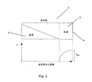
図1は、冷却システムの作動中における蒸発器1を示している。蒸発器1は、第一領域2及び第二領域3を有する。第一領域2は、液相/混合相の状態にある冷媒を含み、すなわち蒸発器1の第一領域2内の冷媒は、液相又は液相と気相冷媒の混合相のいずれかである。第二領域3は、純粋な気相の冷媒を含む。したがって、冷媒の蒸発は、蒸発器1の第二領域3においてではなく蒸発器1の第一領域2で行われ、すなわち第一領域2に対応する蒸発器1の部分だけが、実際には利用される。
FIG. 1 shows the evaporator 1 during operation of the cooling system. The evaporator 1 has a
蒸発器1の下に示されたグラフは、蒸発器1内の位置の関数として、冷媒の過熱度値を示している。過熱度値は蒸発器1の第一領域2において、ゼロであることがわかる。第一領域2と第二領域3との間の境界に到達するとすぐに、蒸発器1の出口開口部4に到達するまで、過熱度値3は増加する。その結果、蒸発器1を出る冷媒の過熱度値は、図1に示した状況において、比較的高いものとなる。
The graph shown below the evaporator 1 shows the superheat value of the refrigerant as a function of the position in the evaporator 1. It can be seen that the superheat value is zero in the
第一領域2と第二領域3との間の境界が蒸発器の出口開口部4に向かって移動することにより、すなわち、第一領域2の長さを増加させ、一方で第二領域3の長さを減少させることにより、蒸発器1を出る冷媒の過熱度値を減少させることができる。理想的には、第二領域3は完全に排除されるべきであり、すなわち、第一領域2が、実質的に蒸発器1全体にわたって延びるようにすべきである。しかしながら、上記したように、大量の液相冷媒が蒸発器1を通過しないように注意しなければならない。
The boundary between the
図2は、蒸発器を含む冷却システムが従来技術の制御計画を使用して作動する場合の、蒸発器を出る冷媒の過熱度値を時間の関数として示すグラフである。過熱度値は、最初は比較的高いが、次第に、実質的に一定で、低いが、正のレベルにまで減少することがわかる。 FIG. 2 is a graph showing the superheat value of the refrigerant exiting the evaporator as a function of time when a cooling system including the evaporator is operated using a prior art control scheme. It can be seen that the superheat value is relatively high initially, but gradually becomes substantially constant and low but decreases to a positive level.
図3は、蒸発器を出る冷媒の過熱度値を、時間の関数として示すグラフである。図3に示される状況においては、蒸発器への冷媒の流れは、本発明の実施形態による方法にしたがって制御される。過熱度値は、最初は比較的高いレベルであり、図2に示される状況と類似して、低いが、正のレベルにまで減少する。過熱度値が低いが、正のレベルに到達すると、本発明による方法の段階が開始される。すなわち、膨張弁の開度は、例えば凡そ10%増加する。これにより、蒸発器への液相冷媒の供給が増加され、その結果蒸発器の第一領域と第二領域との間の境界が、蒸発器の出口開口部の方に移動する。これは、5で示しているように過熱度値を減少させ、過熱度値は、最終的に6のゼロレベルに到達する。この時点で、第一領域は、蒸発器の長さ全体にわたって延び、すなわち液相/混合相冷媒が、蒸発器全体に存在し、蒸発器の乾燥領域は排除される。 FIG. 3 is a graph showing the superheat value of the refrigerant leaving the evaporator as a function of time. In the situation shown in FIG. 3, the refrigerant flow to the evaporator is controlled according to a method according to an embodiment of the invention. The superheat value is initially at a relatively high level and decreases to a low but positive level, similar to the situation shown in FIG. When the superheat value is low but reaches a positive level, the steps of the method according to the invention are started. That is, the opening degree of the expansion valve is increased by about 10%, for example. This increases the supply of liquid phase refrigerant to the evaporator, so that the boundary between the first and second regions of the evaporator moves towards the outlet opening of the evaporator. This reduces the superheat value as shown at 5, which eventually reaches a zero level of 6. At this point, the first zone extends over the entire length of the evaporator, i.e. liquid / mixed phase refrigerant is present throughout the evaporator and the drying zone of the evaporator is eliminated.
時間が経過した後、膨張弁の開度は、増加段階を開始する前の膨張弁の開度にまで減少させることが好ましい。これにより蒸発器への液相冷媒の供給は減少し、第一領域と第二領域との間の境界は、再び出口開口部と反対方向へ移動して、すなわち乾燥領域が蒸発器内に再形成される。これは、過熱度値が8の低いが、正のレベルに到達するまで、7で示しているように、蒸発器を出る冷媒の過熱度値を増加させる。 After the time has elapsed, it is preferable to reduce the opening of the expansion valve to the opening of the expansion valve before starting the increase phase. As a result, the supply of liquid refrigerant to the evaporator is reduced and the boundary between the first region and the second region is moved again in the direction opposite to the outlet opening, i.e. the drying region is restored into the evaporator. It is formed. This increases the superheat value of the refrigerant exiting the evaporator, as shown at 7, until the superheat value is low at 8, but reaches a positive level.
膨張弁の開度を増加及び減少させる段階が繰り返される。これは、過熱度値がゼロレベルと、低いが、正のレベルとの間で「切り換る」ようにするものであることが、図3のグラフから明らかである。これにより、過熱度値の平均値は、前述の低いが、正のレベルより低いレベルとなり、蒸発器の冷却能力は、一層効率的に利用される。しかしながら、蒸発器を通過することが可能な液相冷媒の量は、圧縮器に損傷を与えない程度に十分に小さいものとすることが確実にされる。 The steps of increasing and decreasing the opening of the expansion valve are repeated. It is apparent from the graph of FIG. 3 that this is what causes the superheat value to “switch” between a zero level and a low but positive level. As a result, the average value of the superheat value is low as described above, but lower than the positive level, and the cooling capacity of the evaporator is used more efficiently. However, it is ensured that the amount of liquid phase refrigerant that can pass through the evaporator is small enough that it does not damage the compressor.
図4は、本発明の2つの異なる実施形態に対して、膨張弁の開度を時間の関数として示すグラフである。第一の実施形態9によると、開度は、比較的大きい量だけ増加し、その直後に開度は減少する。第二の実施形態10によると、開度は、幾分小さい量、すなわち第一の実施形態9のおよそ半分の量だけ増加する。第二の実施形態10によると、開度が減少する前に、比較的長い時間、すなわち第一の実施形態9による経過時間のおよそ二倍が経過する。蒸発器に供給される液相冷媒における総増加量は、2つの実施形態9、10とほぼ同じである。これは、斜線部分の面積により示される。
FIG. 4 is a graph showing the expansion valve opening as a function of time for two different embodiments of the present invention. According to the first embodiment 9, the opening degree increases by a relatively large amount, and immediately after that, the opening degree decreases. According to the
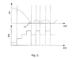
図5は、本発明の別の実施形態について、膨張弁の過熱度及び開度を時間の関数として示している。最初に、蒸発器を出る冷媒の過熱度値は比較的高く、蒸発器の比較的長い部分が、完全な気相冷媒を含むことを示している。過熱度を減少させるために、膨張弁の開度を増加させる。開度が増加すると過熱度に望ましい効果を与え、すなわち過熱度値が減少するが、十分にはゼロ値に到達しないことがわかる。したがって、膨張弁の開度は再び増加し、一層過熱度値を減少させるが、まだゼロレベルに到達するには十分ではない。次いで、膨張弁の開度は、過熱度値が実質的に11のゼロレベルに到達するまで、繰り返して増加される。膨張弁の開度が最後に増加した後、ある程度時間が経過すると、開度は、本発明の方法によって減少される。膨張弁の開度は、上記したように「パルス状」となり、これにより過熱度値を、ゼロレベルと、低いが、正のレベルとの間で「切り換る」ようにすることが可能となる。 FIG. 5 shows the degree of superheat and opening of the expansion valve as a function of time for another embodiment of the present invention. Initially, the superheat value of the refrigerant exiting the evaporator is relatively high, indicating that a relatively long portion of the evaporator contains complete gas phase refrigerant. In order to reduce the degree of superheat, the opening of the expansion valve is increased. It can be seen that increasing the opening gives the desired effect on the degree of superheat, i.e. the superheat value decreases, but does not reach the zero value sufficiently. Thus, the opening of the expansion valve increases again, further reducing the superheat value, but still not enough to reach the zero level. The opening of the expansion valve is then repeatedly increased until the superheat value reaches substantially a zero level of 11. After a certain amount of time has elapsed since the opening of the expansion valve last increased, the opening is reduced by the method of the present invention. The opening of the expansion valve is “pulsed” as described above, which allows the superheat value to be “switched” between zero level and low but positive level. Become.
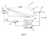
図6は、冷却システムに配置された蒸発器1を示している。膨張弁12は、蒸発器1に供給される液相冷媒の流れを制御する。膨張弁12の開度は、出口4を介して蒸発器1を出る冷媒の過熱度値の測定値を基に制御される。過熱度値は、過熱度センサー13によって計測される。過熱度センサー13は、オフセット・コントローラ14に信号を与え、該オフセット・コントローラ14は、冷却システムの負荷に応じたオフセット・コントロール信号を発生する。過熱度センサー13は、更にパルス・コントローラ15に信号を与え、該パルス・コントローラ15は、膨張弁12の開度の増加/減少のパルス部分の望ましい周波数並びに望ましい振幅に関する情報を含むパルスコントロール信号を発生する。オフセット・コントロール信号及びパルス・コントロール信号は、計算ユニット16において加算される。計算ユニット16は、膨張弁12に、オフセット部分並びにパルス部分を含むコントロール信号を与える。膨張弁12の開度は、コントロール信号によって制御される。
FIG. 6 shows the evaporator 1 arranged in the cooling system. The
図6においては、第一領域2と第二領域3との間の境界が、コントロール信号のパルス部分の結果として、2つの端部位置の間を移動することが示されている。2つの端部位置の1つにおいては、境界は蒸発器1の出口4の位置に移動しており、すなわち蒸発器1を出る冷媒の過熱度値は、上記したようにゼロとなる。他方の端部位置においては、第二領域3が、蒸発器1の長さの凡そ半分を占めており、すなわち蒸発器1を出る冷媒の過熱度値は、比較的高いものとなる。
In FIG. 6, it is shown that the boundary between the
1 蒸発器; 2 第一領域; 3 第二領域; 4 出口開口部; 12 膨張弁;
13 過熱度センサー; 14 オフセット・コントローラ;
15 パルス・コントローラ。
DESCRIPTION OF SYMBOLS 1 Evaporator; 2 1st area | region; 3 2nd area | region; 4 Outlet opening part; 12 Expansion valve;
13 Superheat sensor; 14 Offset controller;
15 Pulse controller.
Claims (8)
前記膨張弁(12)の開度を増加させて、これにより前記蒸発器(1)の乾燥領域(3)を実質的に十分に排除するように前記蒸発器(1)への冷媒の流れを増加させ、
時間が経過した後、前記膨張弁(12)の前記開度を減少させる、
段階と、
前記膨張弁(12)の前記開度を増加及び減少させる前記段階を繰り返す、
段階とから成ることを特徴とする方法。 An evaporator disposed in a cooling system including an expansion valve (12) and a compressor, wherein the expansion valve (12), the compressor and the evaporator are disposed in a refrigerant passage having a refrigerant flow. A method of controlling the flow of refrigerant to (1),
Increasing the opening of the expansion valve (12), thereby allowing the refrigerant flow to the evaporator (1) to substantially completely exclude the drying region (3) of the evaporator (1). Increase,
After a lapse of time, the opening of the expansion valve (12) is decreased;
Stages,
Repeating the steps of increasing and decreasing the opening of the expansion valve (12);
A method characterized by comprising steps.
Applications Claiming Priority (3)
| Application Number | Priority Date | Filing Date | Title |
|---|---|---|---|
| DKPA200801235 | 2008-09-05 | ||
| DKPA200801235 | 2008-09-05 | ||
| PCT/DK2009/000200 WO2010025730A1 (en) | 2008-09-05 | 2009-09-04 | A method for controlling a flow of refrigerant to an evaporator |
Publications (1)
| Publication Number | Publication Date |
|---|---|
| JP2012502245A true JP2012502245A (en) | 2012-01-26 |
Family
ID=41404151
Family Applications (1)
| Application Number | Title | Priority Date | Filing Date |
|---|---|---|---|
| JP2011525406A Pending JP2012502245A (en) | 2008-09-05 | 2009-09-04 | Method for controlling the flow of refrigerant to the evaporator |
Country Status (8)
| Country | Link |
|---|---|
| US (1) | US9217591B2 (en) |
| EP (1) | EP2329205B1 (en) |
| JP (1) | JP2012502245A (en) |
| CN (1) | CN102203525B (en) |
| BR (1) | BRPI0918920A2 (en) |
| MX (1) | MX2011002405A (en) |
| RU (1) | RU2470238C1 (en) |
| WO (1) | WO2010025730A1 (en) |
Families Citing this family (10)
| Publication number | Priority date | Publication date | Assignee | Title |
|---|---|---|---|---|
| KR101224053B1 (en) * | 2010-09-30 | 2013-01-21 | 엘지전자 주식회사 | Clothes treating apparatus with a heat pump system and operating method thereof |
| US9587866B2 (en) | 2010-11-12 | 2017-03-07 | HP Products A/S | System or method for measuring the phase of ammonia in a cooling system |
| US20150135746A1 (en) * | 2012-01-16 | 2015-05-21 | Parker-Hannifin Corporation | Parallel evaporator circuit with balanced flow |
| US9242531B2 (en) * | 2012-03-15 | 2016-01-26 | Ford Global Technologies, Llc | Vehicle climate control method |
| US9188381B2 (en) | 2013-03-21 | 2015-11-17 | Evapco, Inc. | Method and apparatus for initiating coil defrost in a refrigeration system evaporator |
| EP2894421A1 (en) * | 2014-01-14 | 2015-07-15 | Danfoss A/S | A method for controlling a supply of refrigerant to an evaporator based on temperature measurements |
| MX2016014539A (en) * | 2014-05-06 | 2017-08-22 | Evapco Inc | Sensor for coil defrost in a refrigeration system evaporator. |
| WO2017028888A1 (en) * | 2015-08-17 | 2017-02-23 | Electrolux Appliances Aktiebolaget | Control method for a cooling device |
| MX2019012897A (en) | 2017-05-01 | 2020-02-03 | Danfoss As | A method for controlling suction pressure based on a most loaded cooling entity. |
| CN109269134B (en) * | 2018-09-12 | 2019-12-17 | 珠海格力电器股份有限公司 | Heat exchange system control method |
Citations (7)
| Publication number | Priority date | Publication date | Assignee | Title |
|---|---|---|---|---|
| JPS62223571A (en) * | 1986-03-24 | 1987-10-01 | 株式会社東芝 | Method of controlling refrigeration cycle |
| JPS62238109A (en) * | 1986-04-09 | 1987-10-19 | Hitachi Ltd | Refrigerant flow rate control system for automobile |
| US5402652A (en) * | 1984-08-08 | 1995-04-04 | Alsenz; Richard H. | Apparatus for monitoring solenoid expansion valve flow rates |
| JPH09303885A (en) * | 1996-05-08 | 1997-11-28 | Mitsubishi Heavy Ind Ltd | Refrigerating and air conditioning device |
| JP2004225924A (en) * | 2003-01-20 | 2004-08-12 | Mitsubishi Electric Corp | Refrigeration cycle control system |
| JP2006077998A (en) * | 2004-09-07 | 2006-03-23 | Matsushita Electric Ind Co Ltd | Refrigerating cycle device, and control method |
| WO2008024110A1 (en) * | 2006-08-22 | 2008-02-28 | Carrier Corporation | Improved oil return in refrigerant system |
Family Cites Families (10)
| Publication number | Priority date | Publication date | Assignee | Title |
|---|---|---|---|---|
| SU382890A1 (en) * | 1971-06-30 | 1973-05-25 | USSR, 1A reproduction description 11.VII.1973.M. 1 \, 1. F 25L 45/00 F 25L 39 / 02UDK 621.57.048-543.3 (OSS.8) | |
| JPS6136671A (en) * | 1984-07-26 | 1986-02-21 | 三洋電機株式会社 | Controller for flow rate of refrigerant |
| JPH0462358A (en) | 1990-06-29 | 1992-02-27 | Toshiba Corp | Air conditioner |
| US5425246A (en) * | 1994-03-03 | 1995-06-20 | General Electric Company | Refrigerant flow rate control based on evaporator dryness |
| JP3426715B2 (en) | 1994-06-23 | 2003-07-14 | 三洋電機株式会社 | Refrigeration equipment |
| CN2453351Y (en) * | 2000-11-11 | 2001-10-10 | 于洪晶 | Low cost electronic expansion valve |
| EP1369648A3 (en) * | 2002-06-04 | 2004-02-04 | Sanyo Electric Co., Ltd. | Supercritical refrigerant cycle system |
| CN1162667C (en) * | 2003-04-10 | 2004-08-18 | 上海交通大学 | Throttle control mechanism of cross-critical CO2 refrigerating system |
| US20070175229A1 (en) * | 2006-02-01 | 2007-08-02 | Redlich Robert W | Method for controlling a pulsed expansion valve |
| KR20080073475A (en) | 2007-02-06 | 2008-08-11 | 삼성전자주식회사 | An air conditioner and control method of electronic expansion valve thereof |
-
2009
- 2009-09-04 JP JP2011525406A patent/JP2012502245A/en active Pending
- 2009-09-04 RU RU2011112478/06A patent/RU2470238C1/en not_active IP Right Cessation
- 2009-09-04 WO PCT/DK2009/000200 patent/WO2010025730A1/en active Application Filing
- 2009-09-04 MX MX2011002405A patent/MX2011002405A/en not_active Application Discontinuation
- 2009-09-04 BR BRPI0918920A patent/BRPI0918920A2/en not_active IP Right Cessation
- 2009-09-04 EP EP09776196.9A patent/EP2329205B1/en active Active
- 2009-09-04 US US13/062,095 patent/US9217591B2/en active Active
- 2009-09-04 CN CN200980144158.3A patent/CN102203525B/en active Active
Patent Citations (7)
| Publication number | Priority date | Publication date | Assignee | Title |
|---|---|---|---|---|
| US5402652A (en) * | 1984-08-08 | 1995-04-04 | Alsenz; Richard H. | Apparatus for monitoring solenoid expansion valve flow rates |
| JPS62223571A (en) * | 1986-03-24 | 1987-10-01 | 株式会社東芝 | Method of controlling refrigeration cycle |
| JPS62238109A (en) * | 1986-04-09 | 1987-10-19 | Hitachi Ltd | Refrigerant flow rate control system for automobile |
| JPH09303885A (en) * | 1996-05-08 | 1997-11-28 | Mitsubishi Heavy Ind Ltd | Refrigerating and air conditioning device |
| JP2004225924A (en) * | 2003-01-20 | 2004-08-12 | Mitsubishi Electric Corp | Refrigeration cycle control system |
| JP2006077998A (en) * | 2004-09-07 | 2006-03-23 | Matsushita Electric Ind Co Ltd | Refrigerating cycle device, and control method |
| WO2008024110A1 (en) * | 2006-08-22 | 2008-02-28 | Carrier Corporation | Improved oil return in refrigerant system |
Also Published As
| Publication number | Publication date |
|---|---|
| US9217591B2 (en) | 2015-12-22 |
| EP2329205A1 (en) | 2011-06-08 |
| CN102203525A (en) | 2011-09-28 |
| BRPI0918920A2 (en) | 2015-12-01 |
| US20110214438A1 (en) | 2011-09-08 |
| WO2010025730A1 (en) | 2010-03-11 |
| RU2011112478A (en) | 2012-10-10 |
| RU2470238C1 (en) | 2012-12-20 |
| CN102203525B (en) | 2016-01-20 |
| EP2329205B1 (en) | 2017-02-22 |
| MX2011002405A (en) | 2011-04-05 |
Similar Documents
| Publication | Publication Date | Title |
|---|---|---|
| JP2012502245A (en) | Method for controlling the flow of refrigerant to the evaporator | |
| US9003819B2 (en) | Heat pump apparatus using supercooling degree to control expansion valve | |
| JP5095295B2 (en) | Water heater | |
| EP2434233A2 (en) | Refrigeration cycle apparatus and hot-water heating apparatus | |
| JP2010196975A (en) | Refrigerating cycle apparatus | |
| JP6545252B2 (en) | Refrigeration cycle device | |
| JP3659197B2 (en) | Heat pump water heater | |
| EP3199889B1 (en) | Air conditioner | |
| JP3737357B2 (en) | Water heater | |
| JP5708249B2 (en) | Heat pump water heater | |
| JP6136231B2 (en) | Refrigerant flow control device | |
| JP2001208434A (en) | Heat pump hot water supplier | |
| JP3856025B2 (en) | Heat pump water heater | |
| JP2011153789A (en) | Refrigerating cycle device | |
| JP2011179764A (en) | Refrigeration cycle device | |
| JP5125261B2 (en) | Refrigeration equipment | |
| JP4452051B2 (en) | Heat pump water heater | |
| JP5764029B2 (en) | Heat pump water heater and refrigeration cycle | |
| JP2008138971A (en) | Ejector type heat pump cycle | |
| JP2015059708A (en) | Refrigeration device | |
| WO2022044321A1 (en) | Refrigeration cycle system | |
| JP7443887B2 (en) | air conditioner | |
| JP4801420B2 (en) | Control device, control method, and control program | |
| JP6542731B2 (en) | Circulation cooler | |
| JP2000088363A (en) | Heat pump type air conditioner |
Legal Events
| Date | Code | Title | Description |
|---|---|---|---|
| A977 | Report on retrieval |
Free format text: JAPANESE INTERMEDIATE CODE: A971007 Effective date: 20121130 |
|
| A131 | Notification of reasons for refusal |
Free format text: JAPANESE INTERMEDIATE CODE: A131 Effective date: 20121204 |
|
| A521 | Written amendment |
Free format text: JAPANESE INTERMEDIATE CODE: A523 Effective date: 20130304 |
|
| A131 | Notification of reasons for refusal |
Free format text: JAPANESE INTERMEDIATE CODE: A131 Effective date: 20131001 |
|
| A521 | Written amendment |
Free format text: JAPANESE INTERMEDIATE CODE: A523 Effective date: 20140106 |
|
| A02 | Decision of refusal |
Free format text: JAPANESE INTERMEDIATE CODE: A02 Effective date: 20140624 |