JP2012500941A - Rotary piston internal combustion engine - Google Patents
Rotary piston internal combustion engine Download PDFInfo
- Publication number
- JP2012500941A JP2012500941A JP2011525137A JP2011525137A JP2012500941A JP 2012500941 A JP2012500941 A JP 2012500941A JP 2011525137 A JP2011525137 A JP 2011525137A JP 2011525137 A JP2011525137 A JP 2011525137A JP 2012500941 A JP2012500941 A JP 2012500941A
- Authority
- JP
- Japan
- Prior art keywords
- piston
- combustion engine
- wall
- combustion chamber
- crankshaft
- Prior art date
- Legal status (The legal status is an assumption and is not a legal conclusion. Google has not performed a legal analysis and makes no representation as to the accuracy of the status listed.)
- Pending
Links
Images


Classifications
-
- F—MECHANICAL ENGINEERING; LIGHTING; HEATING; WEAPONS; BLASTING
- F02—COMBUSTION ENGINES; HOT-GAS OR COMBUSTION-PRODUCT ENGINE PLANTS
- F02B—INTERNAL-COMBUSTION PISTON ENGINES; COMBUSTION ENGINES IN GENERAL
- F02B53/00—Internal-combustion aspects of rotary-piston or oscillating-piston engines
-
- F—MECHANICAL ENGINEERING; LIGHTING; HEATING; WEAPONS; BLASTING
- F02—COMBUSTION ENGINES; HOT-GAS OR COMBUSTION-PRODUCT ENGINE PLANTS
- F02B—INTERNAL-COMBUSTION PISTON ENGINES; COMBUSTION ENGINES IN GENERAL
- F02B55/00—Internal-combustion aspects of rotary pistons; Outer members for co-operation with rotary pistons
- F02B55/14—Shapes or constructions of combustion chambers
-
- F—MECHANICAL ENGINEERING; LIGHTING; HEATING; WEAPONS; BLASTING
- F01—MACHINES OR ENGINES IN GENERAL; ENGINE PLANTS IN GENERAL; STEAM ENGINES
- F01C—ROTARY-PISTON OR OSCILLATING-PISTON MACHINES OR ENGINES
- F01C17/00—Arrangements for drive of co-operating members, e.g. for rotary piston and casing
- F01C17/06—Arrangements for drive of co-operating members, e.g. for rotary piston and casing using cranks, universal joints or similar elements
-
- F—MECHANICAL ENGINEERING; LIGHTING; HEATING; WEAPONS; BLASTING
- F01—MACHINES OR ENGINES IN GENERAL; ENGINE PLANTS IN GENERAL; STEAM ENGINES
- F01C—ROTARY-PISTON OR OSCILLATING-PISTON MACHINES OR ENGINES
- F01C21/00—Component parts, details or accessories not provided for in groups F01C1/00 - F01C20/00
- F01C21/008—Driving elements, brakes, couplings, transmissions specially adapted for rotary or oscillating-piston machines or engines
-
- F—MECHANICAL ENGINEERING; LIGHTING; HEATING; WEAPONS; BLASTING
- F01—MACHINES OR ENGINES IN GENERAL; ENGINE PLANTS IN GENERAL; STEAM ENGINES
- F01C—ROTARY-PISTON OR OSCILLATING-PISTON MACHINES OR ENGINES
- F01C9/00—Oscillating-piston machines or engines
- F01C9/002—Oscillating-piston machines or engines the piston oscillating around a fixed axis
-
- F—MECHANICAL ENGINEERING; LIGHTING; HEATING; WEAPONS; BLASTING
- F02—COMBUSTION ENGINES; HOT-GAS OR COMBUSTION-PRODUCT ENGINE PLANTS
- F02B—INTERNAL-COMBUSTION PISTON ENGINES; COMBUSTION ENGINES IN GENERAL
- F02B53/00—Internal-combustion aspects of rotary-piston or oscillating-piston engines
- F02B53/02—Methods of operating
-
- F—MECHANICAL ENGINEERING; LIGHTING; HEATING; WEAPONS; BLASTING
- F02—COMBUSTION ENGINES; HOT-GAS OR COMBUSTION-PRODUCT ENGINE PLANTS
- F02B—INTERNAL-COMBUSTION PISTON ENGINES; COMBUSTION ENGINES IN GENERAL
- F02B55/00—Internal-combustion aspects of rotary pistons; Outer members for co-operation with rotary pistons
- F02B55/02—Pistons
-
- F—MECHANICAL ENGINEERING; LIGHTING; HEATING; WEAPONS; BLASTING
- F02—COMBUSTION ENGINES; HOT-GAS OR COMBUSTION-PRODUCT ENGINE PLANTS
- F02B—INTERNAL-COMBUSTION PISTON ENGINES; COMBUSTION ENGINES IN GENERAL
- F02B55/00—Internal-combustion aspects of rotary pistons; Outer members for co-operation with rotary pistons
- F02B55/08—Outer members for co-operation with rotary pistons; Casings
- F02B55/10—Cooling thereof
-
- F—MECHANICAL ENGINEERING; LIGHTING; HEATING; WEAPONS; BLASTING
- F02—COMBUSTION ENGINES; HOT-GAS OR COMBUSTION-PRODUCT ENGINE PLANTS
- F02B—INTERNAL-COMBUSTION PISTON ENGINES; COMBUSTION ENGINES IN GENERAL
- F02B55/00—Internal-combustion aspects of rotary pistons; Outer members for co-operation with rotary pistons
- F02B55/16—Admission or exhaust passages in pistons or outer members
-
- F—MECHANICAL ENGINEERING; LIGHTING; HEATING; WEAPONS; BLASTING
- F16—ENGINEERING ELEMENTS AND UNITS; GENERAL MEASURES FOR PRODUCING AND MAINTAINING EFFECTIVE FUNCTIONING OF MACHINES OR INSTALLATIONS; THERMAL INSULATION IN GENERAL
- F16C—SHAFTS; FLEXIBLE SHAFTS; ELEMENTS OR CRANKSHAFT MECHANISMS; ROTARY BODIES OTHER THAN GEARING ELEMENTS; BEARINGS
- F16C3/00—Shafts; Axles; Cranks; Eccentrics
- F16C3/04—Crankshafts, eccentric-shafts; Cranks, eccentrics
- F16C3/06—Crankshafts
-
- F—MECHANICAL ENGINEERING; LIGHTING; HEATING; WEAPONS; BLASTING
- F01—MACHINES OR ENGINES IN GENERAL; ENGINE PLANTS IN GENERAL; STEAM ENGINES
- F01C—ROTARY-PISTON OR OSCILLATING-PISTON MACHINES OR ENGINES
- F01C17/00—Arrangements for drive of co-operating members, e.g. for rotary piston and casing
- F01C17/06—Arrangements for drive of co-operating members, e.g. for rotary piston and casing using cranks, universal joints or similar elements
- F01C17/066—Arrangements for drive of co-operating members, e.g. for rotary piston and casing using cranks, universal joints or similar elements with an intermediate piece sliding along perpendicular axes, e.g. Oldham coupling
-
- Y—GENERAL TAGGING OF NEW TECHNOLOGICAL DEVELOPMENTS; GENERAL TAGGING OF CROSS-SECTIONAL TECHNOLOGIES SPANNING OVER SEVERAL SECTIONS OF THE IPC; TECHNICAL SUBJECTS COVERED BY FORMER USPC CROSS-REFERENCE ART COLLECTIONS [XRACs] AND DIGESTS
- Y02—TECHNOLOGIES OR APPLICATIONS FOR MITIGATION OR ADAPTATION AGAINST CLIMATE CHANGE
- Y02T—CLIMATE CHANGE MITIGATION TECHNOLOGIES RELATED TO TRANSPORTATION
- Y02T10/00—Road transport of goods or passengers
- Y02T10/10—Internal combustion engine [ICE] based vehicles
- Y02T10/12—Improving ICE efficiencies
Abstract
内燃機関、より詳しくはロータリ内燃機関が提供され、前記機関は、ピストン・ヘッドと円環面の少なくとも一区画を画成するエンジン・ハウジング壁によって境界を定められる複数の燃焼室を有する。さらに、この内燃機関を動作させるための方法が開示される。 An internal combustion engine, and more particularly a rotary internal combustion engine, is provided, the engine having a plurality of combustion chambers bounded by an engine housing wall defining at least a section of a piston head and an annular surface. Further disclosed is a method for operating the internal combustion engine.
Description
本出願は、2005年12月16日出願の米国出願第11/304,608号の一部継続出願であり、その全内容は参照により本出願に組み込まれている。 This application is a continuation-in-part of US application Ser. No. 11 / 304,608, filed Dec. 16, 2005, the entire contents of which are incorporated herein by reference.
本開示は内燃機関に関し、より詳しくはロータリ内燃機関に関する。 The present disclosure relates to internal combustion engines, and more particularly to rotary internal combustion engines.
このセクションの記述は本開示に関連する背景情報のみ提供し、従来技術を構成しない可能性がある。従来型式の燃焼機関では、燃焼室の境界を定める壁は円筒形状であり、一端部でシリンダ・ヘッドで閉じられている。ピストンは、もう1つの端部を介してこのシリンダ内に移動可能にガイドされる。内燃機関は4つの基本的なステップ、すなわち(1)吸入、(2)圧縮、(3)燃焼及び膨張と(4)排気を有する。吸気ステップ中、可燃性混合物が燃焼室内に注入される。この混合物は、シリンダ内へのピストンの圧縮によって圧力下に置かれる。次いでこの混合物は点火され、燃焼させられる。高温の燃焼生成物は最終的に膨張し、ピストンを反対方向に強制的に移動させ、クランクシャフトなどの、ピストンに連結又は結合される機械的な構成部品にエネルギーの伝達を生じさせる。冷却された燃焼生成物は最終的に排気され、この燃焼サイクルが再開する。この原理に従って動作する代表的な燃焼機関は、オットー・エンジン及びディーゼル・エンジンなどにおけるように、2サイクル又は4サイクルで機能することができる。 The descriptions in this section provide only background information relevant to this disclosure and may not constitute prior art. In conventional combustion engines, the walls defining the combustion chamber have a cylindrical shape and are closed at one end by a cylinder head. The piston is movably guided into this cylinder via the other end. An internal combustion engine has four basic steps: (1) intake, (2) compression, (3) combustion and expansion, and (4) exhaust. During the intake step, a combustible mixture is injected into the combustion chamber. This mixture is placed under pressure by compression of the piston into the cylinder. The mixture is then ignited and burned. The hot combustion products eventually expand, forcing the piston in the opposite direction, causing energy transfer to mechanical components, such as a crankshaft, connected or coupled to the piston. The cooled combustion product is finally evacuated and the combustion cycle resumes. Typical combustion engines that operate according to this principle can function in two or four cycles, such as in Otto engines and diesel engines.
従来型の燃焼機関によって示される比較的低い効率に関連する継続的な問題点が存在する。エンジン効率は、エンジンを介して伝達される運動エネルギーの形態で燃料から抽出される有用なエネルギーに対して燃料内の理論的化学エネルギーを比較することによって通常定義される。代表的な燃料からエネルギーを抽出するための熱力学的な限界は約37%であるが、代表的な燃焼機関は約20%の平均効率しか示さない。 There are ongoing problems associated with the relatively low efficiency exhibited by conventional combustion engines. Engine efficiency is usually defined by comparing the theoretical chemical energy in the fuel against useful energy extracted from the fuel in the form of kinetic energy transmitted through the engine. While the thermodynamic limit for extracting energy from a typical fuel is about 37%, a typical combustion engine exhibits an average efficiency of only about 20%.
したがって、高められた効率を提供する内燃機関が継続的に求められている。そのような内燃機関のサイズがよりコンパクトであり、重量がより軽く、内部潤滑の必要性がより少なく、容易に製造できることがさらに望ましい。 Accordingly, there is a continuing need for internal combustion engines that provide increased efficiency. It is further desirable for such internal combustion engines to be more compact in size, lighter in weight, require less internal lubrication and be easily manufactured.
本開示は、効率を改善し、重量及びサイズを減少させ、そのようなエンジンを作るための能力を簡略化する内燃機関を提供する。本開示の一形態では、この内燃機関は、部分的な円環面の軌道に沿って移動する複数のロータリ・ピストンを有する。 The present disclosure provides an internal combustion engine that improves efficiency, reduces weight and size, and simplifies the ability to make such an engine. In one form of the present disclosure, the internal combustion engine has a plurality of rotary pistons that move along a partial toroidal track.
本開示の形態では、内燃機関は、第1の燃焼室の境界を定める第1の壁と第2の燃焼室の境界を定める第2の壁とを伴うハウジングを備え、この第1の壁及び第2の壁のそれぞれは、円環面の少なくとも一区画を画成する。これらの燃焼室は、第1のピストン及び第2のピストンによってさらに境界が定められ、各ピストンは円環面の形状及び2つのピストン・ヘッドを有する。燃焼室の境界を定める壁の端部は、ピストンの端部のところに配置されるピストン・ヘッドのためのガイド部としてさらに機能する。 In an aspect of the present disclosure, an internal combustion engine includes a housing with a first wall that delimits a first combustion chamber and a second wall that delimits a second combustion chamber, the first wall and Each of the second walls defines at least a section of the toric surface. These combustion chambers are further delimited by a first piston and a second piston, each piston having a toroidal shape and two piston heads. The end of the wall that delimits the combustion chamber further functions as a guide for the piston head located at the end of the piston.
第1の燃焼室は、第1のピストンの第1のピストン・ヘッドによって境界がさらに定められる。同様に第2の燃焼室は、第1のピストンの第2のピストン・ヘッドによって境界がさらに定められる。この第1の燃焼室は、やはり第2のピストンの第1のピストン・ヘッドによって境界がさらに定められ、一方第2の燃焼室は、第2のピストン(35)の第2のピストン・ヘッドによってやはり境界がさらに定められる。 The first combustion chamber is further delimited by the first piston head of the first piston. Similarly, the second combustion chamber is further delimited by the second piston head of the first piston. This first combustion chamber is further delimited by the first piston head of the second piston, while the second combustion chamber is defined by the second piston head of the second piston (35). Again, the boundaries are further defined.
本開示の別の形態では、第1のピストンは、第1のコネクティング・ロッドに連結される第1の枢動アームと、共通の枢動点に連結される第2の枢動アームとをさらに備えて示されている。同様に第2のピストンは、第2のコネクティング・ロッドに連結される第1の枢動アームと、共通の枢動点に連結される第2の枢動アームとをさらに備える。各ピストンの第2の枢動アームは、エンジンの中心に向かって半径方向に延びる。 In another form of the present disclosure, the first piston further comprises a first pivot arm coupled to the first connecting rod and a second pivot arm coupled to the common pivot point. Shown in preparation. Similarly, the second piston further comprises a first pivot arm coupled to the second connecting rod and a second pivot arm coupled to a common pivot point. The second pivot arm of each piston extends radially toward the center of the engine.
本開示のさらに別の形態では、第1のクランクシャフトは第1のコネクティング・ロッドに連結され、一方第2のクランクシャフトは第2のコネクティング・ロッドに連結される。この第1のクランクシャフト及び第2のクランクシャフトは、共通の枢動軸によって画成される第1のピストン及び第2のピストンの曲線の軌道と、それぞれ第1の燃焼室及び第2の燃焼室の境界を定める第1の壁及び第2の壁との外側に配置される。 In yet another form of the present disclosure, the first crankshaft is connected to a first connecting rod, while the second crankshaft is connected to a second connecting rod. The first crankshaft and the second crankshaft have a curved path of the first piston and the second piston defined by a common pivot axis, and a first combustion chamber and a second combustion, respectively. Arranged outside the first and second walls that delimit the chamber.
一般に、第1のピストン及び第2のピストンは、共通の枢動軸によって画成される曲線の軌道に沿ってガイドされる。第1のピストンの第2の枢動アーム及び第2のピストンの第2の枢動アームは、共通の枢動軸の周りを揺動する。この第1のピストン及び第2のピストンは反対方向に同時に移動し、それによってピストン・ヘッドは、対応する燃焼室の容積を拡大させる又は減少させるのいずれかを生じさせる。 In general, the first piston and the second piston are guided along a curved trajectory defined by a common pivot axis. The second pivot arm of the first piston and the second pivot arm of the second piston swing about a common pivot axis. The first piston and the second piston move simultaneously in opposite directions, thereby causing the piston head to either expand or decrease the volume of the corresponding combustion chamber.
本開示のさらに別の形態では、第2の枢動アームは係合部材を介してガイド・フレームに連結される。このガイド・フレームは、中に係合部材及び共通の枢動軸が配設される、開口する受け領域を有する。このガイド・フレームは、2本の平行なガイド柱を含むガイド手段と一体化される。このガイド柱に沿ったガイド・フレームの動きは、第2の枢動アームの係合部材を介したガイド・フレームへの結合の結果としてピストンに伝達される。このガイド・フレームがガイド・ポストに沿って一方向に移動するとき、ピストンは円形の軌道に沿って移動し、結果として1つ燃焼室の容積を最小化させ、もう1つの燃焼室の容積を最大化させる。このガイド・フレームが移動する方向を逆転させると、逆の結果になる。 In yet another form of the present disclosure, the second pivot arm is coupled to the guide frame via an engagement member. The guide frame has an open receiving area in which an engaging member and a common pivot shaft are disposed. This guide frame is integrated with a guide means comprising two parallel guide posts. The movement of the guide frame along this guide column is transmitted to the piston as a result of the coupling to the guide frame via the engagement member of the second pivot arm. As the guide frame moves in one direction along the guide post, the piston moves along a circular track, resulting in the minimization of the volume of one combustion chamber and the volume of the other combustion chamber. Maximize. Reversing the direction in which this guide frame moves will result in the opposite.
本開示の別の形態では、ガイド柱に沿ったガイド・フレームの動きは、共通の枢動点に連結される少なくとも1つの長楕円形のプレートの存在によって持続させられる。この長楕円形のプレートによって形成されるモーメントは、曲線の軌道に沿ったピストンの揺動移動を持続させるのに十分である。 In another form of the present disclosure, the movement of the guide frame along the guide column is sustained by the presence of at least one oblong plate coupled to a common pivot point. The moment formed by this oblong plate is sufficient to sustain the oscillating movement of the piston along a curved trajectory.
適用可能性のさらなる領域は、本明細書で提供される記載から明らかになるであろう。この記載及び具体的な実例は説明の目的のためのみであり、本開示の範囲を限定するためのものではないことを理解されたい。 Further areas of applicability will become apparent from the description provided herein. It should be understood that this description and specific examples are for illustrative purposes only and are not intended to limit the scope of the present disclosure.
本明細書に記載される図面は説明の目的のためのみであり、いかなる方式でも本開示の範囲を限定するためのものではない。 The drawings described herein are for illustrative purposes only and are not intended to limit the scope of the present disclosure in any manner.
以下の記載は本質的に例示に過ぎず、決して本開示又はその用途又は使用を限定するためのものではない。この記載及び図面を通して、対応する参照番号は同様な又は対応する部品及び機構を示すことを理解されたい。 The following description is merely exemplary in nature and is in no way intended to limit the present disclosure or the application or uses thereof. Throughout this description and the drawings, it is to be understood that corresponding reference numerals indicate like or corresponding parts and features.
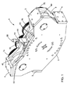
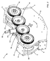
本開示は、特に2サイクル、4サイクルのオットー・エンジン、及びディーゼル・エンジンなどの内燃機関に関する。図1及び2を参照すると、本開示の一形態は、2つのクランクシャフト(45、50)を含むエンジン(1)の構成部品を取り囲むエンジン・ハウジング(5)を有する内燃機関(1)に関する。このエンジン・ハウジング(5)は、単一の構成部品又は互いに締結される複数の構成部品で作ることができる。各クランクシャフト(45、50)は少なくとも1つのフライホイール(75)に連結することができ、追加のフライホイール(76)に連結することも可能である。この内燃機関は排気弁列と吸気弁列の1つ又は両方をさらに備えることができる。現行の実施例は、グロー・プラグ(61)及びシリンダ圧力マウント(60)並びに噴射ポート(55)を備える。その表示される実施例でのこのエンジンは、掃気工程を利用する吸気ポート(62)及び排気ポート(63)を備える。 The present disclosure particularly relates to internal combustion engines such as 2-cycle, 4-cycle Otto engines, and diesel engines. With reference to FIGS. 1 and 2, one form of the present disclosure relates to an internal combustion engine (1) having an engine housing (5) that surrounds the components of the engine (1) including two crankshafts (45, 50). The engine housing (5) can be made of a single component or a plurality of components fastened together. Each crankshaft (45, 50) can be connected to at least one flywheel (75) and can also be connected to an additional flywheel (76). The internal combustion engine may further include one or both of an exhaust valve train and an intake valve train. The current embodiment comprises a glow plug (61) and cylinder pressure mount (60) and an injection port (55). The engine in the displayed embodiment includes an intake port (62) and an exhaust port (63) that utilize a scavenging process.
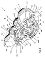
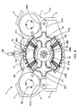
図3〜6を参照すると、本開示の一形態は、第1の燃焼室(11)の境界を定める第1の壁(10)と第2の燃焼室(16)の境界を定める第2の壁(15)を伴うエンジン・ハウジング5(部分的に示す。)を有する内燃機関(1)に関し、この第1の壁(10)及び第2の壁(15)はそれぞれ少なくとも円環面の一区画を画成する。この開示の範囲内では、円環面は共通の枢動点(30)の周りを揺動するピストン(20、35)によって画成されるリング形状を意味すると理解されたい。ピストン・ヘッド(21、36)及び燃焼室(11、16)の横断面形状は円形であるとして示されているが、それらは正方形、長方形又は楕円形などの別の形状であり得ることが可能であり、それらにも限定されない。この燃焼室(11、16)は、第1のピストン(20)及び第2のピストン(35)によってさらに境界が定められ、各ピストンは図4及び6に示すように、円環面形状と2つのピストン・ヘッド(21、36)とを有する。燃焼室(11、16)の境界を定める壁(10、15)の端部は、ピストン(20、35)の端部のところに配置されるピストン・ヘッド(21、36)のためのガイド部としてさらに機能する。 With reference to FIGS. 3-6, one form of the present disclosure provides a second wall defining a first wall (10) delimiting the first combustion chamber (11) and a second combustion chamber (16). For an internal combustion engine (1) having an engine housing 5 (partially shown) with a wall (15), the first wall (10) and the second wall (15) are each at least one of the toroidal surfaces. Define parcels. Within the scope of this disclosure, a toric surface is understood to mean a ring shape defined by pistons (20, 35) that swing about a common pivot point (30). Although the cross-sectional shapes of the piston head (21, 36) and the combustion chamber (11, 16) are shown as being circular, they can be other shapes such as square, rectangular or oval However, it is not limited to them. The combustion chambers (11, 16) are further bounded by a first piston (20) and a second piston (35), each piston having an annular surface shape and 2 as shown in FIGS. Two piston heads (21, 36). The end of the wall (10, 15) delimiting the combustion chamber (11, 16) is a guide for the piston head (21, 36) located at the end of the piston (20, 35). As a further function.
図3、4、及び6では、第1のピストン(20)は、第1のコネクティング・ロッド(25)に連結される第1の枢動アーム(22A)と、共通の枢動点(30)に連結される第2の枢動アーム(22B)をさらに備えるように示されている。同様に、第2のピストン(35)は、第2のコネクティング・ロッド(40)に連結される第1の枢動アーム(37A)と共通の枢動点(30)に連結される第2の枢動アーム(37B)をさらに備える。各ピストン(20、35)のこの第2の枢動アーム(22B、37B)は、エンジンの中央部に向かって半径方向に延びる。本開示の一形態では、第1のコネクティング・ロッド(25)は、第1の接合部軸(100A)を備える第1の接合部のところで第1のピストン(20)の第1のピストンアーム(22A)に連結され、第2のコネクティング・ロッド(40)は、第2の接合部軸(100C)を備える第2の接合部のところで第2のピストン(35)の第2の枢動アーム(37A)に連結される。この第1の枢動アーム(22A)及び第2の枢動アーム(22B)は、共通の枢動軸(100B)を備える共通の枢動点(30)のところで連結される。この第1の接合部軸(100A)、第2の接合部軸(100C)、及び共通の枢動軸(100B)は、共通の面内に位置合わせされるとき互いに平行である。 3, 4 and 6, the first piston (20) has a common pivot point (30) with the first pivot arm (22A) connected to the first connecting rod (25). Is shown to further comprise a second pivot arm (22B) coupled to the. Similarly, the second piston (35) is connected to a first pivot arm (37A) coupled to the second connecting rod (40) and a second pivot point (30) coupled to a common pivot point (30). A pivot arm (37B) is further provided. This second pivot arm (22B, 37B) of each piston (20, 35) extends radially towards the center of the engine. In one form of the present disclosure, the first connecting rod (25) is a first piston arm (1) of the first piston (20) at a first joint comprising a first joint shaft (100A). 22A), the second connecting rod (40) is connected to the second pivot arm (2) of the second piston (35) at the second joint comprising the second joint axis (100C). 37A). The first pivot arm (22A) and the second pivot arm (22B) are connected at a common pivot point (30) with a common pivot axis (100B). The first joint axis (100A), the second joint axis (100C), and the common pivot axis (100B) are parallel to each other when aligned in a common plane.
第1のクランクシャフト(45)は、第1のコネクティング・ロッド(25)に連結され、一方第2のクランクシャフト(50)は、第2のコネクティング・ロッド(40)に連結される。この第1のクランクシャフト(45)及び第2のクランクシャフト(50)は、共通の枢動点(30)によって画成される第1のピストン(20)及び第2のピストン(35)の曲線の軌道と、それぞれ第1の燃焼室(11)及び第2の燃焼室(16)の境界を定める第1の壁(10)及び第2の壁(15)との外側に配置される。このコネクティング・ロッド(25、40)は、エンジンの当業者に知られる、限定はされないが、軸受け及びボルトを含む任意の手段を使用してクランクシャフト(45、50)に連結することができる。 The first crankshaft (45) is connected to the first connecting rod (25), while the second crankshaft (50) is connected to the second connecting rod (40). The first crankshaft (45) and the second crankshaft (50) are curves of the first piston (20) and the second piston (35) defined by a common pivot point (30). , And outside the first wall (10) and the second wall (15) that delimit the first combustion chamber (11) and the second combustion chamber (16), respectively. The connecting rods (25, 40) can be coupled to the crankshaft (45, 50) using any means known to those skilled in the art, including but not limited to bearings and bolts.
各クランクシャフト(45、50)は、例えば変速機輪を介してフライホイール(75)に連結することができる。このクランクシャフト(45、50)は、限定はされないが、チェイン又は歯付ベルトを使用することを含む、当業者に知られている任意の手段によってフライホイール(75)に連結することもできる。この第1のクランクシャフト(45)及び第2のクランクシャフト(50)は、反対方向に回転することができる。第1のクランクシャフト(45)及び第2のクランクシャフト(50)が反対方向に回転するとき追加のフライホイール(76)への連結は簡略化される、何故ならそれらは図2に示すようにクランクシャフト間に直接挿入することができるからである。 Each crankshaft (45, 50) can be coupled to the flywheel (75) via, for example, a transmission wheel. The crankshaft (45, 50) can also be coupled to the flywheel (75) by any means known to those skilled in the art including, but not limited to, using a chain or toothed belt. The first crankshaft (45) and the second crankshaft (50) can rotate in opposite directions. When the first crankshaft (45) and the second crankshaft (50) rotate in opposite directions, the connection to the additional flywheel (76) is simplified, as they are shown in FIG. This is because it can be inserted directly between the crankshafts.
本開示の一形態では、この第1のクランクシャフト(45)は第1のロータリ軸(102A)を備え、第2のクランクシャフト(50)は第2のロータリ軸(102C)を備える。上記で記載されるこの第1のロータリ軸(102A)及び第1の接合部軸(100A)は互いに平行であり、第1の面(103A)内で位置合わせされ、一方第2のロータリ軸(102C)及び第2の接合部軸(100C)は互いに平行であり、第2の面(103C)内で位置合わせされる。第1のピストン(20)と、第2のピストン(35)と、第1の面(103A)と、第2の面(103C)の中心の位置は、第1の接合部軸(100A)と、第2の接合部軸(100C)と、共通の枢動軸(100B)の位置合わせについて上記で記載される共通の面(101)に対して垂直である。 In one form of the present disclosure, the first crankshaft (45) includes a first rotary shaft (102A) and the second crankshaft (50) includes a second rotary shaft (102C). The first rotary axis (102A) and the first joint axis (100A) described above are parallel to each other and aligned within the first surface (103A), while the second rotary axis ( 102C) and the second joint axis (100C) are parallel to each other and aligned within the second plane (103C). The position of the center of the first piston (20), the second piston (35), the first surface (103A), and the second surface (103C) is the same as the first joint axis (100A). , Perpendicular to the common plane (101) described above for the alignment of the second joint axis (100C) and the common pivot axis (100B).
それぞれ第1の燃焼室(11)及び第2の燃焼室(16)の境界を定める第1の壁(10)及び第2の壁(15)は、単一の構成部品として、又は複数の構成部品として構築することができる。本開示の一形態では、この第1の壁(10)及び第2の壁(15)は、互いに締結される(右及び左の)2つの構成部品として構築される。そのような締結は、限定はされないが、ボルト及び接着剤の使用を含む、エンジンの当業者に知られている任意の手段によって実施することができる。ガスケット及び封止剤の使用を、この壁を含むこれらの締結される(右及び左の)構成部品間に生じる可能性のある、起こりうるどのような漏れの発生も減少させるために行うことができる。 The first wall (10) and the second wall (15) that delimit the first combustion chamber (11) and the second combustion chamber (16), respectively, may be a single component or a plurality of configurations. Can be built as a part. In one form of the present disclosure, the first wall (10) and the second wall (15) are constructed as two components that are fastened together (right and left). Such fastening may be performed by any means known to those skilled in the art of engines, including but not limited to the use of bolts and adhesives. The use of gaskets and sealants can be made to reduce any possible leaks that may occur between these fastened (right and left) components including this wall. it can.
図3に示すように、この第1の壁(10)及び第2の壁(15)は、冷却溝(17)をさらに備えることができる。これらの冷却溝(17)は、燃焼室(11、16)と、ピストン・ヘッド(21、36)と、ピストン(20、35)とに冷却効果を与えるために、空気などの気体の流れ、又は水又は油などの液体の流れを使用することができる。そのような冷却効果は、壁から離れる熱の、冷却溝(17)内を流れる液体又は気体への熱伝達の結果として得られる。 As shown in FIG. 3, the first wall (10) and the second wall (15) may further include a cooling groove (17). These cooling grooves (17) provide a flow of gas, such as air, to provide a cooling effect to the combustion chambers (11, 16), the piston heads (21, 36), and the pistons (20, 35). Or a liquid stream such as water or oil can be used. Such a cooling effect is obtained as a result of heat transfer away from the wall to the liquid or gas flowing in the cooling groove (17).
エンジン(1)は、吸気ポート(62)と、排気ポート(63)と、シリンダ圧力マウント(60)と、第1の壁(10)及び第2の壁(15)のうちの少なくとも1つの内部のスパーク・プラグ又はグロー・プラグ(61)とをさらに備えることができる。ダブル・スパーク点火システムを設けることもできる。通常、この吸気ポート(62)及び排気ポート(63)は、第1の壁(10)及び第2の壁(15)のうちの少なくとも1つの中で燃焼室(11、16)と交差する。その上、燃料噴射器ポートが、燃焼室(11、16)のうちの少なくとも1つと交差するように設けられる。燃焼室(11、16)、吸気(62)ポート及び排気(63)ポートと噴射器ポート(55)との間の交差の角度は約90度である。2サイクルの実施例の通常の掃気工程中、この排気ポート(63)は吸気ポート(62)より長い時間にわたって開いていることが好ましい。 The engine (1) includes at least one of an intake port (62), an exhaust port (63), a cylinder pressure mount (60), and a first wall (10) and a second wall (15). A spark plug or a glow plug (61). A double spark ignition system can also be provided. Usually, the intake port (62) and the exhaust port (63) intersect the combustion chamber (11, 16) in at least one of the first wall (10) and the second wall (15). In addition, a fuel injector port is provided to intersect at least one of the combustion chambers (11, 16). The angle of intersection between the combustion chamber (11, 16), the intake (62) port and the exhaust (63) port and the injector port (55) is about 90 degrees. During the normal scavenging process of the two cycle embodiment, this exhaust port (63) is preferably open for a longer time than the intake port (62).
次に図2を参照すると、第1の燃焼室(11)は、第1のピストン(20)の第1のピストン・ヘッド(21A)によってさらに境界が定められる。第2の燃焼室(16)は、第1のピストン(20)の第2のピストン・ヘッド(21B)によってさらに境界が定められる。この第1の燃焼室(11)は、第2のピストン(35)の第1のピストン・ヘッド(36A)によってやはりさらに境界が定められ、一方第2の燃焼室(16)は、第2のピストン(35)の第2のピストン・ヘッド(36B)によってやはりさらに境界が定められる。図6Bに示すような本開示の一形態では、この第1のピストン(20)の第1のピストン・ヘッド(21A)及び第2のピストン・ヘッド(21B)は、互いにある角度(αl)を形成し、一方第2のピストン(35)の第1のピストン・ヘッド(36A)及び第2のピストン・ヘッド(36B)はある角度(α2)を形成する。角度(α1)及び(α2)は少なくとも110度であることが好ましい。ピストン・ヘッド(21、36)は、ピストン・ヘッドをエンジン・ハウジング(5)の壁(10、15)に対して封止するピストン・リング(85)を含むことができる。 Referring now to FIG. 2, the first combustion chamber (11) is further delimited by the first piston head (21A) of the first piston (20). The second combustion chamber (16) is further delimited by the second piston head (21B) of the first piston (20). This first combustion chamber (11) is also further delimited by the first piston head (36A) of the second piston (35), while the second combustion chamber (16) The second piston head (36B) of the piston (35) is also further delimited. In one form of the present disclosure as shown in FIG. 6B, the first piston head (21A) and the second piston head (21B) of the first piston (20) have an angle (αl) with respect to each other. While the first piston head (36A) and the second piston head (36B) of the second piston (35) form an angle (α2). The angles (α1) and (α2) are preferably at least 110 degrees. The piston head (21, 36) can include a piston ring (85) that seals the piston head against the walls (10, 15) of the engine housing (5).
第1のピストン(20)と、第2のピストン(35)と、ピストン・ヘッド(21、36)と、第1の壁(10)又は第2の壁(15)は、金属、炭素複合材料、又は特にセラミック複合材料から構成することができる。このピストン・ヘッド(21、36)は、グラファイト複合材料から作ることができる。ピストン(20、35)及びピストン・ヘッド(21、36)は、用途に応じて完全に中実又は部分的に中空のいずれかであることができる。金属の例には、限定はされないが、アルミニウム及び熱処理鋼を含むことができる。セラミック複合材料の例には、特に炭化珪素又は窒化珪素を含むことができる。炭素複合材料及びセラミック複合材料の強度は、繊維強化を用いて高めることができる。 The first piston (20), the second piston (35), the piston head (21, 36), the first wall (10) or the second wall (15) are made of metal, carbon composite material Or in particular from ceramic composite materials. The piston head (21, 36) can be made from a graphite composite material. The piston (20, 35) and the piston head (21, 36) can be either completely solid or partially hollow depending on the application. Examples of metals can include, but are not limited to, aluminum and heat treated steel. Examples of ceramic composite materials can include silicon carbide or silicon nitride, among others. The strength of carbon composites and ceramic composites can be increased using fiber reinforcement.
ピストン・ヘッド(21、36)及び壁(10、15)によって画成される燃焼室(11、16)の形状は、限定はされないが、円錐又は円筒形状を含む、エンジン燃焼の当業者に知られる任意の形状であることができる。本開示のエンジン(1)内のピストン(20、35)の動きは、順次的に図6A〜6Cに示す。図6Aでは、ピストン(20、35)は上方位置に回転させられ、それによってピストン・ヘッド(21A、36A)は燃焼室(11)の容積を減少させ、一方ピストン・ヘッド(21B、36B)は燃焼室(16)の容積を増加させる。ピストン(20、35)が中間位置に回転させられるとき(図6B参照)、燃焼室(11、16)の容積は同様になる。図6Cでは、ピストン(20、35)は下方位置に回転させられ、それによってピストン・ヘッド(21B、36B)は燃焼室(16)の容積を減少させ、一方ピストン・ヘッド(21A、36A)は燃焼室(11)の容積を増加させる。 The shape of the combustion chamber (11, 16) defined by the piston head (21, 36) and wall (10, 15) is known to those skilled in the art of engine combustion, including but not limited to a conical or cylindrical shape. Can be of any shape. The movements of the pistons (20, 35) in the engine (1) of the present disclosure are shown sequentially in FIGS. In FIG. 6A, the piston (20, 35) is rotated to an upper position, whereby the piston head (21A, 36A) reduces the volume of the combustion chamber (11), while the piston head (21B, 36B) Increase the volume of the combustion chamber (16). When the pistons (20, 35) are rotated to the intermediate position (see FIG. 6B), the volumes of the combustion chambers (11, 16) are similar. In FIG. 6C, the piston (20, 35) is rotated to a lower position, whereby the piston head (21B, 36B) reduces the volume of the combustion chamber (16), while the piston head (21A, 36A) Increase the volume of the combustion chamber (11).
次に図7〜8を参照すると、ピストン・プレート(65)と主部材プレート(70)の組み合わせが各ピストン・ヘッド(21、36)を対応するピストン(20、35)に連結するために使用される。ピストン・プレート(65)と主部材プレート(70)の組み合わせを1つしか図示していないが、当業者は誰もそのようなプレート(65、70)の組み合わせを各ピストン・ヘッド(21、36)に使用できることを理解するであろう。プレート(65、70)のこの組み合わせは、様々な種類のボルト及び接続具(66、67)を使用してピストン・ヘッド(21、36)に締結することができる。これらのプレート(65、70)の目的は、モータの動作中に生じる力をピストン(20、35)から対応するピストン・ヘッド(21、36)に、より均一に伝達し、分配することである。これらの力の伝達は、そのような結合部の近くの応力及び潜在的に可能性のある破損、例えば応力割れの形成の危険性を減少させるために、ピストン(20、35)へのプレートの組み合わせ(65、70)の広い結合領域にわたって行われる。 7-8, the combination of piston plate (65) and main member plate (70) is used to connect each piston head (21, 36) to the corresponding piston (20, 35). Is done. Although only one combination of the piston plate (65) and the main member plate (70) is shown, any person skilled in the art will recognize such a combination of plates (65, 70) for each piston head (21, 36). ) Will be understood. This combination of plates (65, 70) can be fastened to the piston head (21, 36) using various types of bolts and fittings (66, 67). The purpose of these plates (65, 70) is to more uniformly transmit and distribute the forces generated during the operation of the motor from the pistons (20, 35) to the corresponding piston heads (21, 36). . The transmission of these forces reduces the risk of stresses near such joints and potentially possible breaks, for example the formation of stress cracks, of the plate to the piston (20, 35). This is done over a wide bonding area of the combination (65, 70).
次に図9を参照すると、共通の枢動点(30)によって画定される曲線の軌道に沿ってガイドされる第1のピストン(20)及び第2のピストン(35)を有するロータリ内燃機関の別の形態を示す。この曲線の軌道は図9に矢印(80)によって指示されている。第1の枢動アーム(22A、37A)は、ピストン(20、35)によって形成される円環面の外側に配置されるクランクシャフト(図示せず)に連結される。図9は、ピストンの移動又は動きと、各ピストン(20、35)の第2の枢動アーム(22B、37B)の共通の枢動点(30)との相互作用を説明するためのものである。第1のピストン(20)の第2の枢動アーム(22B)及び第2のピストン(35)の第2の枢動アーム(37B)は、共通の枢動点(30)の周りを揺動する。この第1のピストン(20)及び第2のピストン(35)は反対方向に同時に移動し、その結果、ピストン・ヘッド(21、36)は、対応する燃焼室(11、16)の容積を膨張又は減少のいずれかを生じさせる。図9Aには、これらのピストン(20、35)は両方共それらの頂部位置内に回転しており、その結果、第1の燃焼室(11)の容積を減少させ、第2の燃焼室(16)の容積を増加させる。ピストン(20、35)がそれらの頂部位置から底部位置に移動するとき、第1の燃焼室(11)の容積はより大きくなり、第2の燃焼室(16)の容積はより小さくなる。 Referring now to FIG. 9, a rotary internal combustion engine having a first piston (20) and a second piston (35) guided along a curved trajectory defined by a common pivot point (30). Another form is shown. The trajectory of this curve is indicated by the arrow (80) in FIG. The first pivot arms (22A, 37A) are connected to a crankshaft (not shown) arranged outside the annular surface formed by the pistons (20, 35). FIG. 9 illustrates the interaction or movement of the piston with the common pivot point (30) of the second pivot arm (22B, 37B) of each piston (20, 35). is there. The second pivot arm (22B) of the first piston (20) and the second pivot arm (37B) of the second piston (35) swing about a common pivot point (30). To do. The first piston (20) and the second piston (35) move simultaneously in opposite directions, so that the piston head (21, 36) expands the volume of the corresponding combustion chamber (11, 16). Or cause a decrease. In FIG. 9A, these pistons (20, 35) are both rotating into their top positions, resulting in a decrease in the volume of the first combustion chamber (11) and the second combustion chamber ( 16) Increase the volume. As the pistons (20, 35) move from their top position to the bottom position, the volume of the first combustion chamber (11) becomes larger and the volume of the second combustion chamber (16) becomes smaller.
図9Bには、共通の枢動軸(100B)を備える共通の枢動点(30)に枢動アーム(37A、37B)を介して連結されるクランクシャフトによって画成される曲線の軌道(80)に従うピストン(35)の移動を示す。もう1つのピストン(20)は、実質的に同様に移動すると予想される。この第2の枢動アーム(37B)は、係合部材(91)を介してガイド・フレーム(90)に連結される。このガイド・フレーム(90)は、第2の枢動アーム(37B)と実質的に平行になるように配置される。ガイド・フレーム(90)は、中に係合部材(91)及び共通の枢動点(30)が配設される開口する受け領域を有する。ガイド・フレーム(90)は、2本の平行なガイド柱(93R、93L)を含むガイド手段(92)と一体化されている。このガイド・フレーム(90)は、ガイド柱(93)によって示される方向に移動することができる。ガイド柱(93)に沿ったガイド・フレーム(90)の動きは、係合部材(91)を介して第2の枢動アーム(37B)がガイド・フレーム(90)へ結合されるのでピストン(35)に伝達される。ガイド・フレーム(90)がガイド・ポスト(93)に沿って上向き方向に移動するとき、ピストン(20、35)は円形軌道に沿って移動し、結果として図4Aに示すように燃焼室(11)の容積を最小限にし、燃焼室(16)の容積を最大にする。このピストンの移動はさらに、本出願の権利者が所有する(2006年5月30日出願の)米国特許出願第11/442,401号に記載されており、その内容は参照により本明細書に組み込まれている。 FIG. 9B shows a curved trajectory (80 defined by a crankshaft connected via a pivot arm (37A, 37B) to a common pivot point (30) with a common pivot axis (100B). ) Shows the movement of the piston (35) following. The other piston (20) is expected to move substantially similarly. The second pivot arm (37B) is connected to the guide frame (90) via the engagement member (91). The guide frame (90) is arranged to be substantially parallel to the second pivot arm (37B). The guide frame (90) has an open receiving area in which the engagement member (91) and the common pivot point (30) are disposed. The guide frame (90) is integrated with guide means (92) including two parallel guide columns (93R, 93L). The guide frame (90) can move in the direction indicated by the guide post (93). The movement of the guide frame (90) along the guide column (93) is such that the second pivot arm (37B) is coupled to the guide frame (90) via the engagement member (91) so that the piston ( 35). As the guide frame (90) moves upward along the guide post (93), the pistons (20, 35) move along a circular path, resulting in a combustion chamber (11 as shown in FIG. 4A). ) And the volume of the combustion chamber (16) is maximized. This piston movement is further described in US patent application Ser. No. 11 / 442,401 (filed May 30, 2006) owned by the right holder of this application, the contents of which are hereby incorporated by reference. It has been incorporated.
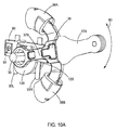
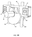
次に図10Aを参照すると、曲線の軌道(80)に沿ったピストン(35)及びその関連するピストン・ヘッド(36A、36B)の移動についての、本開示による別の実施例を示す。この実施例では、このガイド・フレーム(90)は、共通の枢動点(30)に、並びに係合部材(91)を介して第2の枢動アーム(37B)に連結される。少なくとも1つの長楕円形のプレート(120)が共通の枢動点(30)と連結される。1つの長楕円形のプレート(120)が図10Bに示すように、ガイド・フレーム(90)の両側に配置されるのが好ましい。この長楕円形のプレート(120)が共通の枢動点(30)の周りを回転させられ、ガイド・フレーム(90)がガイド・ポスト(93)に沿って上向き又は下向き方向に移動するとき、この長楕円形のプレート(120)の移動によって発生するモーメントは、曲線の軌道(80)に沿ったピストン(35)の揺動移動を維持することができる。 Referring now to FIG. 10A, another embodiment in accordance with the present disclosure is shown for movement of the piston (35) and its associated piston head (36A, 36B) along a curved trajectory (80). In this embodiment, the guide frame (90) is connected to a common pivot point (30) and to a second pivot arm (37B) via an engagement member (91). At least one oblong plate (120) is connected to a common pivot point (30). One oblong plate (120) is preferably disposed on each side of the guide frame (90) as shown in FIG. 10B. When this oblong plate (120) is rotated around a common pivot point (30) and the guide frame (90) moves upward or downward along the guide post (93), The moment generated by the movement of the oblong plate (120) can maintain the oscillating movement of the piston (35) along the curved path (80).
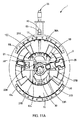
本開示に示すようなロータリ燃焼機関に対する様々な実施例は、クランクシャフト(45、50)がピストン(20、35)のトロイダル軌道の外側にあるように示されてきたが、当業者はこのクランクシャフトをピストンのトロイダル軌道の直径の内側に位置決めすることができることを理解するであろう。クランクシャフトがピストンのトロイダル軌道の直径の内側に位置決めされる、本開示の一実施例の一例が、図11A及び11Bに示されている。クランクシャフトがこの方式で設けられるとき、第1のピストン及び第2のピストン(20、35)は、それを介してフライホイール(図示せず)への連結を行うことができるクランク・ピン(150)を有する共通の枢動点(30)に結合されるピストンアーム(22B、37B)を備える。 While various embodiments for a rotary combustion engine as shown in the present disclosure have been shown with the crankshaft (45, 50) outside the toroidal track of the piston (20, 35), those skilled in the art will recognize that this crank It will be appreciated that the shaft can be positioned inside the diameter of the toroidal track of the piston. An example of one embodiment of the present disclosure in which the crankshaft is positioned inside the piston toroidal track diameter is shown in FIGS. 11A and 11B. When the crankshaft is provided in this manner, the first piston and the second piston (20, 35) are connected via a crank pin (150) which can be connected to a flywheel (not shown). ) With piston arms (22B, 37B) coupled to a common pivot point (30).
図11A及び11Bにおいて、内燃機関(1)には第1の燃焼室(11)の境界を定める第1の壁(10)と第2の燃焼室(16)の境界を定める第2の壁(15)を伴うエンジン・ハウジング5(部分的に示す。)を有する内燃機関(1)が設けられ、第1の壁(10)及び第2の壁(15)はそれぞれ、円環面の少なくとも一区画を画成する。この燃焼室(11、16)は第1のピストン(20)及び第2のピストン(35)によってさらに境界が定められ、各ピストンは円環面形状と2つのピストン・ヘッド(21、36)を有する。この燃焼室(11、16)の境界を定める壁(10、15)の端部は、ピストン(20、35)の端部のところに配置されるピストン・ヘッド(21、36)のためのガイド部としてさらに機能する。この第1のピストン(20)及び第2のピストン(35)は反対方向に同時に移動し、それによってピストン・ヘッド(21、36)は、対応する燃焼室(11、16)の容積の膨張又は減少のいずれかを生じさせる。一実施例では、このピストン(20、35)の移動は、ピストン(20、35)の揺動を持続させることができる少なくとも1つの長楕円形のプレート(120)と共に、クランク・ピン(150)を有する共通の枢動点(30)に連結されるガイド・フレーム(90)を有する、図10に指示される機構を使用することができる。このエンジン(1)は、吸気ポート(62)と、排気ポート(63)と、グロー・プラグ(61)と、第1の壁(10)と第2の壁(15)のうちの少なくとも1つの中の、燃焼室(11、16)と交差するシリンダ圧力マウント(60)とをさらに備えることができる。 11A and 11B, the internal combustion engine (1) has a first wall (10) that defines the boundary of the first combustion chamber (11) and a second wall that defines the boundary of the second combustion chamber (16) ( 15) is provided with an engine housing 5 (partially shown) with a first wall (10) and a second wall (15) each having at least one annular surface. Define parcels. This combustion chamber (11, 16) is further delimited by a first piston (20) and a second piston (35), each piston having a toroidal shape and two piston heads (21, 36). Have. The ends of the walls (10, 15) delimiting this combustion chamber (11, 16) are guides for the piston heads (21, 36) located at the ends of the pistons (20, 35). It further functions as a part. The first piston (20) and the second piston (35) move simultaneously in opposite directions so that the piston heads (21, 36) expand or expand the volume of the corresponding combustion chamber (11, 16). Cause one of the reductions. In one embodiment, this movement of the piston (20, 35) is accompanied by at least one oblong plate (120) that can sustain the oscillation of the piston (20, 35), as well as the crank pin (150). The mechanism indicated in FIG. 10 can be used having a guide frame (90) coupled to a common pivot point (30) having The engine (1) includes at least one of an intake port (62), an exhaust port (63), a glow plug (61), a first wall (10), and a second wall (15). A cylinder pressure mount (60) that intersects the combustion chamber (11, 16) may be further included.
当業者は前述の記載から、以下の特許請求の範囲に定義される本開示の範囲から逸脱することなく、さらなる改変及び変更を行うことができることを認識するであろう。 Those skilled in the art will recognize from the foregoing description that further modifications and changes may be made without departing from the scope of the present disclosure as defined in the following claims.
Claims (28)
前記第1の燃焼室の境界をさらに定める第1のピストン・ヘッドと、前記第2の燃焼室の境界をさらに定める第2のピストン・ヘッドと、第1のコネクティング・ロッドに連結される第1の枢動アームと、共通の枢動点に連結される第2の枢動アームとを有する第1のピストンと、
前記第1の燃焼室の境界をさらに定める第1のピストン・ヘッドと、前記第2の燃焼室の境界をさらに定める第2のピストン・ヘッドと、第2のコネクティング・ロッドに連結される第1の枢動アームと、前記共通の枢動点に連結される第2の枢動アームとを有する第2のピストンと、
前記第1のコネクティング・ロッドに連結される第1のクランクシャフトと、前記第2のコネクティング・ロッドに連結される第2のクランクシャフトとを備え、
前記第1のピストン及び第2のピストンが前記共通の枢動点によって画成される曲線の軌道に沿ってガイドされ、
前記第1のピストン及び第2のピストンが反対方向に移動し、
前記第1のピストンの前記第2の枢動アーム及び前記第2のピストンの前記第2の枢動アームが前記共通の枢動点の周りを揺動する、内燃機関。 A first wall defining a boundary of the first combustion chamber and a second wall defining a boundary of the second combustion chamber, wherein each of the first wall and the second wall is at least one annular surface An engine housing defining the compartment;
A first piston head further defining a boundary of the first combustion chamber; a second piston head further defining a boundary of the second combustion chamber; and a first connected to a first connecting rod. A first piston having a pivot arm and a second pivot arm coupled to a common pivot point;
A first piston head further defining a boundary of the first combustion chamber; a second piston head further defining a boundary of the second combustion chamber; and a first connected to a second connecting rod. And a second piston having a second pivot arm coupled to the common pivot point;
A first crankshaft coupled to the first connecting rod; and a second crankshaft coupled to the second connecting rod;
The first piston and the second piston are guided along a curved trajectory defined by the common pivot point;
The first piston and the second piston move in opposite directions;
An internal combustion engine, wherein the second pivot arm of the first piston and the second pivot arm of the second piston swing about the common pivot point.
中で係合部材がガイド・フレームをピストンの第2の枢動アームに連結する開口する受け領域を有するガイド・フレームと、
2本の平行なガイド柱を含むガイド手段とをさらに備え、
前記ガイド柱に沿った前記ガイド・フレームの動きがピストンに伝達される、請求項1に記載の燃焼機関。 The common pivot point is
A guide frame having an open receiving area in which the engagement member connects the guide frame to the second pivot arm of the piston;
Guide means including two parallel guide columns,
The combustion engine of claim 1, wherein movement of the guide frame along the guide post is transmitted to a piston.
少なくとも1つの長楕円形のプレートをさらに備え、
前記長楕円形のプレートの移動により発生するモーメントによって前記ピストンの揺動移動が維持される、請求項8に記載の燃焼機関。 The common pivot point is
Further comprising at least one oblong plate;
The combustion engine according to claim 8, wherein the swing movement of the piston is maintained by a moment generated by the movement of the oblong plate.
少なくとも1つの燃焼室内に燃料を噴射するステップと、
前記燃料を燃焼させ、その結果化学的エネルギーの解放と燃焼副産物の形成が得られるステップと、
化学的エネルギーの前記解放に起因して、前記ピストン・ヘッドを強制的に移動させるステップと、
前記ピストン・ヘッドに連結されるピストンの移動を介して、前記化学的エネルギーを機械的なエネルギーに変えるステップと、
前記機械的なエネルギーを前記ピストンに連結される少なくとも1つのクランクシャフトに伝達するステップと、
前記燃焼生成物を前記燃焼室から通気させるステップとを含み、
各壁及び各ピストンが円環面の少なくとも一区画を画成し、
前記ピストンが、共通の枢動点によって画成される曲線の軌道に沿って反対方向に移動する、方法。 Operating an internal combustion engine having a first combustion chamber delimited by two piston heads and a first wall and a second combustion chamber delimited by two piston heads and a second wall A method,
Injecting fuel into at least one combustion chamber;
Burning said fuel, resulting in the release of chemical energy and the formation of combustion by-products;
Forcibly moving the piston head due to the release of chemical energy;
Converting the chemical energy into mechanical energy via movement of a piston coupled to the piston head;
Transmitting the mechanical energy to at least one crankshaft coupled to the piston;
Venting the combustion products from the combustion chamber;
Each wall and each piston defines at least one section of an annular surface;
The piston moves in the opposite direction along a curved trajectory defined by a common pivot point.
前記第1の燃焼室の境界をさらに定める第1のピストン・ヘッドと、前記第2の燃焼室の境界をさらに定める第2のピストン・ヘッドと、クランク・ピンを有する共通の枢動点に連結される枢動アームとを有する第1のピストンと、
前記第1の燃焼室の境界をさらに定める第1のピストン・ヘッドと、前記第2の燃焼室の境界をさらに定める第2のピストン・ヘッドと、クランク・ピンを有する前記共通の枢動点に連結される枢動アームとを有する第2のピストンと、
前記共通の枢動点の前記クランク・ピンに連結され、中で係合部材がガイド・フレームをピストンの枢動アームに連結する、開口する受け領域を有する前記ガイド・フレームと、
前記ガイド・フレームによって摺動可能に受けられる2本の平行なガイド柱を含むガイド手段と、
前記共通の枢動点の前記クランク・ピンに連結される少なくとも1つの長楕円形のプレートとを備え、
前記第1のピストン及び第2のピストンが、前記共通の枢動点によって画成される曲線の軌道に沿ってガイドされ、
前記第1のピストン及び第2のピストンが反対方向に移動し、
前記第1のピストンの前記枢動アーム及び前記第2のピストンの前記枢動アームが前記共通の枢動点の周りを揺動し、
前記ガイド柱に沿った前記ガイド・フレームの動きがピストンに伝達され、
前記長楕円形のプレートの移動によって発生するモーメントによって、前記ピストンの前記揺動移動が維持される、内燃機関。 A first wall defining a boundary of the first combustion chamber and a second wall defining a boundary of the second combustion chamber, wherein each of the first wall and the second wall is at least an annular surface An engine housing defining a section;
A first piston head that further delimits the first combustion chamber, a second piston head that further demarcates the second combustion chamber, and a common pivot point having a crank pin A first piston having a pivot arm to be operated;
A first piston head further defining a boundary of the first combustion chamber; a second piston head further defining a boundary of the second combustion chamber; and the common pivot point having a crank pin. A second piston having a pivot arm coupled thereto;
Said guide frame having an open receiving area coupled to said crank pin at said common pivot point, wherein an engagement member couples the guide frame to a pivot arm of a piston;
Guide means comprising two parallel guide posts slidably received by the guide frame;
At least one oblong plate coupled to the crank pin of the common pivot point;
The first piston and the second piston are guided along a curved trajectory defined by the common pivot point;
The first piston and the second piston move in opposite directions;
The pivot arm of the first piston and the pivot arm of the second piston swing about the common pivot point;
Movement of the guide frame along the guide column is transmitted to the piston;
The internal combustion engine, wherein the swing movement of the piston is maintained by a moment generated by the movement of the oblong plate.
Applications Claiming Priority (3)
| Application Number | Priority Date | Filing Date | Title |
|---|---|---|---|
| US12/197,522 US8033265B2 (en) | 2005-12-16 | 2008-08-25 | Rotary piston internal combustion engine |
| US12/197,522 | 2008-08-25 | ||
| PCT/US2009/054875 WO2010027778A2 (en) | 2008-08-25 | 2009-08-25 | Rotary piston internal combustion engine |
Related Child Applications (1)
| Application Number | Title | Priority Date | Filing Date |
|---|---|---|---|
| JP2012266144A Division JP5635061B2 (en) | 2008-08-25 | 2012-12-05 | Rotary piston internal combustion engine |
Publications (2)
| Publication Number | Publication Date |
|---|---|
| JP2012500941A true JP2012500941A (en) | 2012-01-12 |
| JP2012500941A5 JP2012500941A5 (en) | 2012-05-31 |
Family
ID=41797775
Family Applications (2)
| Application Number | Title | Priority Date | Filing Date |
|---|---|---|---|
| JP2011525137A Pending JP2012500941A (en) | 2008-08-25 | 2009-08-25 | Rotary piston internal combustion engine |
| JP2012266144A Active JP5635061B2 (en) | 2008-08-25 | 2012-12-05 | Rotary piston internal combustion engine |
Family Applications After (1)
| Application Number | Title | Priority Date | Filing Date |
|---|---|---|---|
| JP2012266144A Active JP5635061B2 (en) | 2008-08-25 | 2012-12-05 | Rotary piston internal combustion engine |
Country Status (6)
| Country | Link |
|---|---|
| US (3) | US8033265B2 (en) |
| EP (1) | EP2324202B1 (en) |
| JP (2) | JP2012500941A (en) |
| KR (1) | KR101318114B1 (en) |
| CN (1) | CN102187060B (en) |
| WO (1) | WO2010027778A2 (en) |
Cited By (1)
| Publication number | Priority date | Publication date | Assignee | Title |
|---|---|---|---|---|
| JP2015532963A (en) * | 2012-09-25 | 2015-11-16 | − グスタフ ライサー、ハインツ | Orbital planetary gearing system and internal combustion engine employing the same |
Families Citing this family (16)
| Publication number | Priority date | Publication date | Assignee | Title |
|---|---|---|---|---|
| US8033265B2 (en) * | 2005-12-16 | 2011-10-11 | Reisser Heinz-Gustav A | Rotary piston internal combustion engine |
| US8944015B2 (en) * | 2005-12-16 | 2015-02-03 | Heinz-Gustav A. Reisser | Rotary piston internal combustion engine |
| JP4140017B1 (en) * | 2007-06-05 | 2008-08-27 | 樹伸 大森 | Rotating piston engine correlation crank |
| EP2321498A2 (en) * | 2008-08-04 | 2011-05-18 | LiquidPiston, Inc. | Isochoric heat addition engines and methods |
| US9239002B2 (en) | 2010-08-03 | 2016-01-19 | Heinz-Gustav Reisser | Orbiting planetary gearing system and internal combustion engine employing the same |
| US20120085313A1 (en) * | 2010-10-12 | 2012-04-12 | Reisser Heinz-Gustav A | Piston-head design for use in an internal combustion engine |
| ITBO20110124A1 (en) * | 2011-03-15 | 2012-09-16 | Bergamini Giorgio | ROTATING MOTOR. |
| WO2012135556A2 (en) | 2011-03-29 | 2012-10-04 | Liquidpiston, Inc. | Cycloid rotor engine |
| CN102588092B (en) * | 2012-03-02 | 2014-07-09 | 冯卓群 | Two-stroke self-suction rotating engine |
| EP2925966B1 (en) * | 2012-09-25 | 2020-05-20 | Reisser, Heinz-Gustav | Internal combustion engine employing an orbiting planetary gearing system |
| CN103277191B (en) * | 2013-05-07 | 2015-07-01 | 宁波特能机电有限公司 | Annular reciprocating type piston engine and even permutation annular reciprocating type piston engine |
| US9784180B2 (en) | 2014-09-04 | 2017-10-10 | Steve Gorth | Apparatus and method for an articulating inner structure of an engine chamber |
| CN104653461A (en) * | 2014-12-15 | 2015-05-27 | 康立业 | Swing type gas compressor |
| US10829290B2 (en) * | 2016-07-27 | 2020-11-10 | Hbl Holdings, Llc | Vacuum sealable container with internal pump mechanism |
| CN108691642A (en) * | 2017-04-11 | 2018-10-23 | 江乃宽 | Swinging internal combustion engine system with annular compression expansion tank |
| GB202014614D0 (en) * | 2020-09-16 | 2020-10-28 | Carnot Ltd | Internal combustion engine |
Citations (11)
| Publication number | Priority date | Publication date | Assignee | Title |
|---|---|---|---|---|
| JPS5465211A (en) * | 1977-11-04 | 1979-05-25 | Mitsubishi Heavy Ind Ltd | Piston for internal combustion engine |
| JPS627937A (en) * | 1985-07-01 | 1987-01-14 | Kawasaki Heavy Ind Ltd | Vertically-mounted 2-shaft type engine |
| JPS62117240U (en) * | 1986-01-20 | 1987-07-25 | ||
| JPH04292527A (en) * | 1991-03-20 | 1992-10-16 | Honda Motor Co Ltd | Two-cycle engine |
| JPH04507272A (en) * | 1990-01-18 | 1992-12-17 | ムラッケン,ジョイ,ピー. | Compression/combustion assembly |
| JPH09151748A (en) * | 1995-11-29 | 1997-06-10 | Kazuo Kimiwada | Parallel reciprocating engine |
| JP2002265272A (en) * | 2001-03-06 | 2002-09-18 | Isuzu Ceramics Res Inst Co Ltd | Fiber reinforced silicon nitride ceramic composite material |
| US20070137613A1 (en) * | 2005-12-16 | 2007-06-21 | Reisser Heinz-Gustav A | Internal combustion engine |
| JP2007239502A (en) * | 2006-03-06 | 2007-09-20 | Toyota Motor Corp | Internal combustion engine with two crankshafts |
| US20070277765A1 (en) * | 2006-05-30 | 2007-12-06 | Reisser Heinz-Gustav A | Internal combustion engine |
| US20070283922A1 (en) * | 2006-06-08 | 2007-12-13 | Reisser Heinz-Gustav A | Internal combustion engine |
Family Cites Families (42)
| Publication number | Priority date | Publication date | Assignee | Title |
|---|---|---|---|---|
| US1497481A (en) * | 1924-06-10 | A common law trust consisting of | ||
| US3258618A (en) * | 1966-06-28 | Magnetohydrodynamic internal combustion electric generator | ||
| US1428858A (en) | 1922-09-12 | Internal-combustion engine | ||
| US1095034A (en) * | 1912-10-29 | 1914-04-28 | Antonio Sanchez | Rotary internal-combustion engine. |
| US1348675A (en) * | 1918-08-03 | 1920-08-03 | Weed Differentialrotary Motor | Rotary engine |
| US1568053A (en) * | 1923-06-09 | 1926-01-05 | Bullington Motors | Multicylinder rotary engine |
| US2167946A (en) | 1933-05-15 | 1939-08-01 | Gar Wood | Internal combustion engine |
| US2124327A (en) * | 1936-02-01 | 1938-07-19 | Harry F Wolstenholme | Rotary internal combustion engine |
| US2123279A (en) * | 1936-05-28 | 1938-07-12 | Warren E George | Internal combustion engine |
| US2264648A (en) | 1937-08-30 | 1941-12-02 | Tebaldi Alessandro | Explosion engine |
| US2132595A (en) * | 1937-11-17 | 1938-10-11 | Bancroft Charles | Displacement means |
| US2303025A (en) | 1942-05-04 | 1942-11-24 | Stanley E Cliff | Internal combustion engine |
| US2413589A (en) | 1943-08-05 | 1946-12-31 | Henrietta B Snyder | Rotary internal-combustion engine |
| US2387467A (en) * | 1944-06-28 | 1945-10-23 | Harry E Reiter | Internal-combustion engine |
| US2416846A (en) * | 1944-11-20 | 1947-03-04 | Richter Charles | Oscillating piston internal-combustion engine |
| US3307525A (en) * | 1964-05-05 | 1967-03-07 | Mcclure Corp Of America | Rotary piston expansible chamber machine |
| US3292602A (en) * | 1964-11-02 | 1966-12-20 | George R Stewart | Rotary engine |
| US3396632A (en) * | 1966-04-19 | 1968-08-13 | Leblanc Michel | Volumetric maching suitable for operation as pump, engine, or motor pump |
| US3580228A (en) * | 1969-05-20 | 1971-05-25 | Octavio Rocha | Oscillating internal combustion engine |
| US3645239A (en) * | 1969-10-24 | 1972-02-29 | Arnulfo Q Cena | Rotary piston machine |
| US3702746A (en) * | 1971-11-01 | 1972-11-14 | James K Parmerlee | Rotary free piston gas generator |
| US4084550A (en) * | 1973-07-02 | 1978-04-18 | Peter Gaspar | Rotary engines |
| US4136661A (en) * | 1977-02-25 | 1979-01-30 | Posson Chester A | Rotary engine |
| FR2475127A1 (en) * | 1980-02-06 | 1981-08-07 | Snecma | VOLUME VARIATION GAS GENERATOR |
| DE3006940C2 (en) * | 1980-02-25 | 1983-01-27 | Sabet, Huschang, Dipl-.Ing., 7000 Stuttgart | Center-axis rotary piston internal combustion engine |
| DE3305852A1 (en) | 1983-02-19 | 1984-08-23 | Albert 6683 Spiesen Wagner | Two-stroke diesel engine with opposed free pistons |
| US4738235A (en) * | 1985-11-06 | 1988-04-19 | Raincor, Inc. | Rotary engine having controller and transfer gears |
| DE4209444A1 (en) | 1992-03-24 | 1993-09-30 | Boehm Hans Joachim Dipl Ing | Rotary vane piston engine - has crankpins on each crankshaft displaced at 180 degrees on crank axis |
| US5203287A (en) * | 1992-08-07 | 1993-04-20 | Tommy Hasbun | Oscillating piston engine |
| GB9604818D0 (en) * | 1996-03-07 | 1996-05-08 | Seal Edward | Internal combustion engine |
| SE508376C2 (en) | 1996-07-12 | 1998-09-28 | Gul & Co Dev Ab | Lubrication device for internal combustion engine with power transmission via a cam curve track |
| KR100235175B1 (en) * | 1997-05-31 | 1999-12-15 | 김창균 | Pressure pump and internal engine |
| US6036461A (en) * | 1997-07-03 | 2000-03-14 | Bahniuk, Inc. | Expansible chamber device having rotating piston braking and rotating piston synchronizing systems |
| US6164263A (en) * | 1997-12-02 | 2000-12-26 | Saint-Hilaire; Roxan | Quasiturbine zero vibration-continuous combustion rotary engine compressor or pump |
| US6242928B1 (en) | 1998-01-16 | 2001-06-05 | Denso Corporation | Method and apparatus for detecting resistance of oxygen concentration sensor |
| US5996538A (en) * | 1998-06-03 | 1999-12-07 | Rocha; Octavio | Two-cycle internal combustion engine and method of operation |
| US6230671B1 (en) | 1998-11-02 | 2001-05-15 | Raymond C. Achterberg | Variable compression and asymmetrical stroke internal combustion engine |
| GB9928067D0 (en) * | 1999-11-29 | 2000-01-26 | Parker Brian | Improved engine and drive system |
| US6467270B2 (en) | 2001-01-31 | 2002-10-22 | Cummins Inc. | Exhaust gas recirculation air handling system for an internal combustion engine |
| US6739307B2 (en) * | 2002-03-26 | 2004-05-25 | Ralph Gordon Morgado | Internal combustion engine and method |
| US6880494B2 (en) * | 2003-07-22 | 2005-04-19 | Karl V. Hoose | Toroidal internal combustion engine |
| US8033265B2 (en) * | 2005-12-16 | 2011-10-11 | Reisser Heinz-Gustav A | Rotary piston internal combustion engine |
-
2008
- 2008-08-25 US US12/197,522 patent/US8033265B2/en active Active
-
2009
- 2009-08-25 WO PCT/US2009/054875 patent/WO2010027778A2/en active Application Filing
- 2009-08-25 KR KR1020117006733A patent/KR101318114B1/en active IP Right Grant
- 2009-08-25 EP EP09791880.9A patent/EP2324202B1/en active Active
- 2009-08-25 CN CN200980140662.6A patent/CN102187060B/en active Active
- 2009-08-25 JP JP2011525137A patent/JP2012500941A/en active Pending
-
2011
- 2011-06-07 US US13/155,150 patent/US8944025B2/en active Active
-
2012
- 2012-12-05 JP JP2012266144A patent/JP5635061B2/en active Active
-
2014
- 2014-12-18 US US14/574,791 patent/US20150101557A1/en not_active Abandoned
Patent Citations (11)
| Publication number | Priority date | Publication date | Assignee | Title |
|---|---|---|---|---|
| JPS5465211A (en) * | 1977-11-04 | 1979-05-25 | Mitsubishi Heavy Ind Ltd | Piston for internal combustion engine |
| JPS627937A (en) * | 1985-07-01 | 1987-01-14 | Kawasaki Heavy Ind Ltd | Vertically-mounted 2-shaft type engine |
| JPS62117240U (en) * | 1986-01-20 | 1987-07-25 | ||
| JPH04507272A (en) * | 1990-01-18 | 1992-12-17 | ムラッケン,ジョイ,ピー. | Compression/combustion assembly |
| JPH04292527A (en) * | 1991-03-20 | 1992-10-16 | Honda Motor Co Ltd | Two-cycle engine |
| JPH09151748A (en) * | 1995-11-29 | 1997-06-10 | Kazuo Kimiwada | Parallel reciprocating engine |
| JP2002265272A (en) * | 2001-03-06 | 2002-09-18 | Isuzu Ceramics Res Inst Co Ltd | Fiber reinforced silicon nitride ceramic composite material |
| US20070137613A1 (en) * | 2005-12-16 | 2007-06-21 | Reisser Heinz-Gustav A | Internal combustion engine |
| JP2007239502A (en) * | 2006-03-06 | 2007-09-20 | Toyota Motor Corp | Internal combustion engine with two crankshafts |
| US20070277765A1 (en) * | 2006-05-30 | 2007-12-06 | Reisser Heinz-Gustav A | Internal combustion engine |
| US20070283922A1 (en) * | 2006-06-08 | 2007-12-13 | Reisser Heinz-Gustav A | Internal combustion engine |
Cited By (1)
| Publication number | Priority date | Publication date | Assignee | Title |
|---|---|---|---|---|
| JP2015532963A (en) * | 2012-09-25 | 2015-11-16 | − グスタフ ライサー、ハインツ | Orbital planetary gearing system and internal combustion engine employing the same |
Also Published As
| Publication number | Publication date |
|---|---|
| JP5635061B2 (en) | 2014-12-03 |
| KR20110053367A (en) | 2011-05-20 |
| US8033265B2 (en) | 2011-10-11 |
| WO2010027778A3 (en) | 2010-08-26 |
| JP2013083263A (en) | 2013-05-09 |
| CN102187060B (en) | 2015-04-08 |
| KR101318114B1 (en) | 2013-10-16 |
| US8944025B2 (en) | 2015-02-03 |
| US20110297117A1 (en) | 2011-12-08 |
| EP2324202A2 (en) | 2011-05-25 |
| US20150101557A1 (en) | 2015-04-16 |
| WO2010027778A2 (en) | 2010-03-11 |
| CN102187060A (en) | 2011-09-14 |
| EP2324202B1 (en) | 2017-11-15 |
| US20080314350A1 (en) | 2008-12-25 |
Similar Documents
| Publication | Publication Date | Title |
|---|---|---|
| JP5635061B2 (en) | Rotary piston internal combustion engine | |
| JP2012500941A5 (en) | ||
| JP5690772B2 (en) | Internal combustion engine | |
| US7516723B2 (en) | Double piston cycle engine | |
| JP3016485B2 (en) | Reciprocating 2-cycle internal combustion engine without crank | |
| US7415962B2 (en) | Internal combustion engine | |
| JP2004536252A (en) | Split 4-stroke cycle internal combustion engine | |
| JP2013539516A (en) | Piston structure for opposed piston engine | |
| US6119650A (en) | Energy conservation cycle engine | |
| US20030136356A1 (en) | Piston compressed turbine engine and control method thereof | |
| US6250263B1 (en) | Dual piston cylinder configuration for internal combustion engine | |
| US7237542B2 (en) | Internal combustion engine | |
| RU2125162C1 (en) | Piston engine | |
| RU2144142C1 (en) | Internal combustion engine with rocking piston | |
| JPH0828274A (en) | Combustion chamber and combustion method for contracted combustion chamber type internal combustion engine | |
| JP2008002300A (en) | Horizontal operation engine | |
| JPH03134254A (en) | Continuous combustion-type thermal engine | |
| UA52802C2 (en) | “mykola-2” internal combustion rotor engine with skew axes of rotation of rotors | |
| RU93033773A (en) | NEW DIESEL WITH CONVERTER |
Legal Events
| Date | Code | Title | Description |
|---|---|---|---|
| A977 | Report on retrieval |
Free format text: JAPANESE INTERMEDIATE CODE: A971007 Effective date: 20120406 |
|
| A521 | Written amendment |
Free format text: JAPANESE INTERMEDIATE CODE: A523 Effective date: 20120406 |
|
| A131 | Notification of reasons for refusal |
Free format text: JAPANESE INTERMEDIATE CODE: A131 Effective date: 20120410 |
|
| A131 | Notification of reasons for refusal |
Free format text: JAPANESE INTERMEDIATE CODE: A131 Effective date: 20120605 |
|
| A601 | Written request for extension of time |
Free format text: JAPANESE INTERMEDIATE CODE: A601 Effective date: 20120905 |
|
| A602 | Written permission of extension of time |
Free format text: JAPANESE INTERMEDIATE CODE: A602 Effective date: 20120912 |
|
| A601 | Written request for extension of time |
Free format text: JAPANESE INTERMEDIATE CODE: A601 Effective date: 20121005 |
|
| A602 | Written permission of extension of time |
Free format text: JAPANESE INTERMEDIATE CODE: A602 Effective date: 20121015 |
|
| A601 | Written request for extension of time |
Free format text: JAPANESE INTERMEDIATE CODE: A601 Effective date: 20121105 |
|
| A602 | Written permission of extension of time |
Free format text: JAPANESE INTERMEDIATE CODE: A602 Effective date: 20121112 |
|
| A521 | Written amendment |
Free format text: JAPANESE INTERMEDIATE CODE: A523 Effective date: 20121205 |
|
| A131 | Notification of reasons for refusal |
Free format text: JAPANESE INTERMEDIATE CODE: A131 Effective date: 20130402 |
|
| A601 | Written request for extension of time |
Free format text: JAPANESE INTERMEDIATE CODE: A601 Effective date: 20130628 |
|
| A602 | Written permission of extension of time |
Free format text: JAPANESE INTERMEDIATE CODE: A602 Effective date: 20130705 |
|
| A601 | Written request for extension of time |
Free format text: JAPANESE INTERMEDIATE CODE: A601 Effective date: 20130802 |
|
| A602 | Written permission of extension of time |
Free format text: JAPANESE INTERMEDIATE CODE: A602 Effective date: 20130809 |
|
| A02 | Decision of refusal |
Free format text: JAPANESE INTERMEDIATE CODE: A02 Effective date: 20131105 |