JP2012255559A - Flow control valve - Google Patents
Flow control valve Download PDFInfo
- Publication number
- JP2012255559A JP2012255559A JP2012193865A JP2012193865A JP2012255559A JP 2012255559 A JP2012255559 A JP 2012255559A JP 2012193865 A JP2012193865 A JP 2012193865A JP 2012193865 A JP2012193865 A JP 2012193865A JP 2012255559 A JP2012255559 A JP 2012255559A
- Authority
- JP
- Japan
- Prior art keywords
- spool
- input port
- housing
- output port
- pressure
- Prior art date
- Legal status (The legal status is an assumption and is not a legal conclusion. Google has not performed a legal analysis and makes no representation as to the accuracy of the status listed.)
- Granted
Links
Images

Landscapes
- Safety Valves (AREA)
Abstract
Description
本発明は、流体の流量を制御すべく用いられる流量制御弁に関する。 The present invention relates to a flow control valve used to control the flow rate of a fluid.
従来、流体の流量を制御すべく設けられる流量制御弁として、スプール収納室内に進退可能に収納してなり入口側流路に向け開口する固定オリフィス及び出口側流路に向け開口し出口側流路との間の相対移動に伴い開口幅を変更可能な可変オリフィスを有するスプールを具備するものが広く用いられている(例えば、特許文献1を参照)。 Conventionally, as a flow control valve provided to control the flow rate of fluid, it is housed in a spool housing chamber so as to be able to advance and retreat, and opens toward an inlet-side channel and opens toward an outlet-side channel and exit-side channel Those having a spool having a variable orifice whose opening width can be changed with relative movement between the two and the like are widely used (see, for example, Patent Document 1).
このような流量制御弁において、スプールとスプール収納室との間の摺動面は、流体の漏れを少なくすべく、隙間がμm単位となるように仕上げている。しかして、この隙間の形状が適正なものでない場合には、特に弁の下流の圧力が大きい場合、隙間内の流体の圧力分布が軸対象とならずにスプールをスプール収納室の内壁に向けて押し付ける横力が発生し、スプールが作動しにくくなることがある。 In such a flow control valve, the sliding surface between the spool and the spool storage chamber is finished so that the gap is in μm units so as to reduce fluid leakage. Therefore, when the shape of the gap is not appropriate, especially when the pressure downstream of the valve is large, the pressure distribution of the fluid in the gap is not targeted for the shaft, and the spool is directed toward the inner wall of the spool storage chamber. A lateral force to be pressed is generated, and the spool may be difficult to operate.
また、このような流量制御弁では、弁の上流側と下流側との間の差圧を利用してスプールを駆動するため、スプールと収納室の内壁との間の圧力勾配は弁の下流側の圧力に応じて変化する。特に、弁の下流側が低圧である場合は、前記圧力勾配が大きくなり、これにつれてスプールを収納室の内壁に向けて押し付ける横力が大きくなり、スプールが動きにくくなる不具合が発生することがある。 Further, in such a flow control valve, the spool is driven by utilizing the differential pressure between the upstream side and the downstream side of the valve, so the pressure gradient between the spool and the inner wall of the storage chamber is on the downstream side of the valve. Varies depending on the pressure. In particular, when the downstream side of the valve is at a low pressure, the pressure gradient increases, and as a result, the lateral force that presses the spool toward the inner wall of the storage chamber increases, which may cause a problem that the spool is difficult to move.
本発明は、以上を踏まえ、スプールを収納室の内壁に向けて押し付ける横力を低下させ、スプールをよりスムーズに動作させるようにすることを目的とする。 In view of the above, an object of the present invention is to reduce the lateral force that presses the spool toward the inner wall of the storage chamber so that the spool operates more smoothly.
すなわち本発明に係る流量制御弁の一つは、入力ポート及び出力ポートを開口させてなるハウジングと、このハウジング内に摺動可能に嵌装してなり入力ポートに向け開口する固定オリフィス及び出力ポートに向け開口し進退動作に伴い出力ポートへの通路を開閉する可変オリフィスを有するスプールを具備するものであって、このスプールの前記ハウジングに摺動する摺動面に、該スプールの周方向に延伸する円周溝と、前記入力ポート及び前記円周溝に連通する圧力導入溝を設けてなることを特徴とする。 That is, one of the flow control valves according to the present invention includes a housing in which an input port and an output port are opened, and a fixed orifice and an output port that are slidably fitted in the housing and open toward the input port. A spool having a variable orifice that opens and closes and opens and closes the passage to the output port in accordance with the forward / backward movement, and extends in a circumferential direction of the spool on a sliding surface that slides on the housing. And a pressure introducing groove communicating with the input port and the circumferential groove.
また、本発明に係る流量制御弁の他の一つは、入力ポート及び出力ポートを開口させてなるハウジングと、このハウジング内に摺動可能に嵌装してなり入力ポートに向け開口する固定オリフィス及び出力ポートに向け開口し進退動作に伴い出力ポートへの通路を開閉する可変オリフィスを有するスプールを具備するものであって、このスプールの前記ハウジングに摺動する摺動面に、前記入力ポートに連通し該スプールの進退方向に延伸する圧力導入溝を周方向に等間隔で複数設けてなることを特徴とする。 Further, another flow control valve according to the present invention includes a housing in which an input port and an output port are opened, and a fixed orifice that is slidably fitted in the housing and opens toward the input port. And a spool having a variable orifice that opens toward the output port and opens and closes the passage to the output port in accordance with the forward / backward movement, and on the sliding surface that slides on the housing of the spool, A plurality of pressure introducing grooves that are communicated and extend in the advancing / retreating direction of the spool are provided at equal intervals in the circumferential direction.
これらのような構成によれば、圧力導入溝の先端までは入口側流路と液圧が等しくなるので、圧力勾配を受ける部位はこの圧力導入溝の先端から可変オリフィスの入口側流路寄り端縁までであり、従来の構成と比較して圧力勾配を受ける部位が少なくなる。従って、圧力勾配により発生する横力を受ける部位もまた少なくなり、スプール収納室の内壁によりスプールの進退方向をガイドしつつスプールをよりスムーズに操作させるようにすることができる。 According to such a configuration, since the fluid pressure is equal to that of the inlet-side flow path up to the tip of the pressure introduction groove, the portion receiving the pressure gradient is from the tip of the pressure introduction groove to the end near the inlet-side flow path of the variable orifice. As far as the edge, there are fewer sites subject to pressure gradients compared to conventional configurations. Accordingly, the portion receiving the lateral force generated by the pressure gradient is also reduced, and the spool can be operated more smoothly while guiding the forward / backward direction of the spool by the inner wall of the spool storage chamber.
本発明に係る流量制御弁の構造によれば、圧力導入溝の先端までは入口側流路と液圧が等しくなるので、圧力勾配を受ける部位はこの圧力導入溝の先端から可変オリフィスの入口側流路寄り端縁までであり、従来の構成と比較して圧力勾配を受ける部位が少なくなる。従って、圧力勾配により発生する横力を受ける部位もまた少なくなり、スプール収納室の内壁によりスプールの進退方向をガイドしつつスプールをよりスムーズに操作させるようにすることができる。 According to the structure of the flow control valve according to the present invention, since the fluid pressure is equal to the inlet side flow path up to the tip of the pressure introduction groove, the portion receiving the pressure gradient is from the tip of the pressure introduction groove to the inlet side of the variable orifice. It is to the edge near the flow path, and there are fewer parts that receive a pressure gradient as compared with the conventional configuration. Accordingly, the portion receiving the lateral force generated by the pressure gradient is also reduced, and the spool can be operated more smoothly while guiding the forward / backward direction of the spool by the inner wall of the spool storage chamber.
以下、本発明の一実施形態を、図面を参照して説明する。 Hereinafter, an embodiment of the present invention will be described with reference to the drawings.
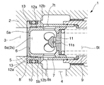
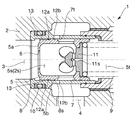
本実施形態に係る流量制御弁1は、図1及び図2に示すように、入力ポート3及び出力ポート4を開口させてなるハウジング2と、このハウジング2内に摺動可能に嵌装してなり入力ポート3に向け開口する固定オリフィス6及び出力ポート4に向け開口し進退動作に伴い出力ポート4への通路を開閉する可変オリフィス7を有するスプール5を具備する。また、この流量制御弁1は、液圧回路の作動液や気体流路の気体等の流体の流量を制御すべく用いられる。
As shown in FIGS. 1 and 2, the flow control valve 1 according to the present embodiment has a
さらに詳述すると、前記ハウジング2には、前記図1及び図2に示すように、入力ポート3と、出力ポート4と、これら入力ポート3及び出力ポート4に連通し内部にスリーブ8を収納してなるスプール収納室2sとを有する。また、このスプール収納室2s内には、スプール5を入力ポート3側に付勢するための付勢手段たるスプリング9を収納している。ここで、前記スリーブ8には、前記スプール5の可変オリフィス7と前記出力ポート4との間に位置し、前記スプール5の進退に伴い可変オリフィス7の一部のみを出力ポート4に連通させ出力ポート4へ吐出される流量を調整する可変絞りとして機能する可変絞り孔8sを設けている。また、このスリーブ8とハウジング2との間には、作動液の入力ポート3から出力ポート4への漏れを防ぐべくOリング10を配している。そして、前記スリーブ8内に前記スプール5を摺動可能に嵌装してなる。
More specifically, as shown in FIGS. 1 and 2, the
一方、前記スプール5には、上述したように、また、前記図1、前記図2、及び図3に示すように、入力ポート3に向け開口する固定オリフィス6と、出力ポート4に向け開口し進退動作に伴い出力ポート4への通路を開閉する可変オリフィス7とを有する。また、このスプール5の内部空間5sは、前記固定オリフィス6及び前記可変オリフィス7に連通するとともに、この内部空間5sの前記入力ポート3に向かう面である受圧面5aと反対側すなわち固定オリフィス6と反対側には、前記スプリングの自由端を接続するためのリテーナ部材11を設けていて、このリテーナ部材11を介してスプリング9から入力ポート側に向かう弾性付勢力を受けるようにしている。また、このリテーナ部材11によりスプールの内部空間5sとスプリング9を収納するスプリング収納室5tとを区画するようにしているとともに、このリテーナ部材11には、前記スプールの内部空間5s及び前記スプリング収納室5tを連通する絞り11sを設けている。なお、前記スプリング9の固定端は、図示は省略しているが、前記スプリング収納室5tの前記入力ポートと反対側の内壁に接続している。
On the other hand, the
しかして本実施形態では、前記図1、前記図2、及び図3に示すように、このスプール5の前記ハウジング2、より具体的には前記スリーブ8に摺動する摺動面5bに、該スプール5の周方向に延伸する第1及び第2の円周溝12a、12bと、前記入力ポート3及び前記第1の円周溝12aに連通する圧力導入溝13とを設けている。
Accordingly, in this embodiment, as shown in FIGS. 1, 2 and 3, the
前記第1の円周溝12aは、本実施形態では前記受圧面5aと前記可変オリフィス7の入力ポート3側端縁7tとの中間に設けてなる。前記第2の円周溝12bは、この第1の円周溝12aと前記可変オリフィス7の入力ポート3側端縁7tとの中間に設けてなる。
In the present embodiment, the first
一方、前記圧力導入溝13は、上述したように前記受圧面5aからこのスプール5の進退方向に沿って前記第1の円周溝12aと連通する位置まで延伸している。また、本実施形態では、この圧力導入溝13は、互いに周方向に離間させて複数本を等間隔に設けている。
On the other hand, the
ここで、出力ポート4側の液圧が高い場合、すなわち入力ポート3側と出力ポート4側の差圧が小さい場合には、図1に示すように、スプール5は入力ポート3側に位置し、可変オリフィス7の開度は大きくなる。一方、スプール5の摺動面5bとスリーブ8の内面との間の隙間にも作動液が入り込む。特に、前記第1の円周溝12aには前記圧力導入溝13を介して入力ポート3側から作動液が入り込むので、受圧面5aの側端縁から前記第1の円周溝12aまでの部位の液圧は入力ポート3側の液圧と等しくなる。すなわち、受圧面5aの側端縁から前記第1の円周溝12aまでの部位はスプール5の進退方向をガイドする機能のみを有し、前記第1の円周溝12aから前記可変オリフィス7の入力ポート3側端縁7tまでの部位のみが圧力勾配を受ける。
Here, when the hydraulic pressure on the output port 4 side is high, that is, when the differential pressure between the
また、出力ポート4側の液圧が低くなると、すなわち入力ポート2側と出力ポート3側の差圧が大きくなると、図2に示すように、スプール5は入力ポート3から離間し、可変オリフィス7の開度は小さくなる。一方、この場合にも、スプール5の摺動面5bとスリーブ8の内面との間の隙間に作動液が入り込む。特に、前記第1の円周溝12aには前記圧力導入溝13を介して入力ポート3側から作動液が入り込むので、受圧面5aの側端縁から前記第1の円周溝12aまでの部位の液圧は入力ポート3側の液圧と等しくなる。すなわち、この場合であっても受圧面5aの側端縁から前記第1の円周溝12aまでの部位はスプール5の進退方向をガイドする機能のみを有し、前記第1の円周溝12aから前記可変オリフィス7の入力ポート3側端縁7tのみが圧力勾配を受ける。
When the hydraulic pressure on the output port 4 side decreases, that is, when the differential pressure between the
これに対して、従来の円周溝のみを設けるスプールを利用する態様では、受圧面から可変オリフィスの端縁までの部位の全体が圧力勾配を受ける。 On the other hand, in the aspect using the conventional spool having only the circumferential groove, the entire part from the pressure receiving surface to the end edge of the variable orifice receives a pressure gradient.
すなわち、本実施形態に係る流量調整弁の構成によれば、従来の構成と比較して、圧力勾配を受ける部位、すなわちスプール5をスプール収納室2sの内壁に向けて押し付ける横力が作用する部位を小さくしつつ、受圧面5aの側端縁から前記可変オリフィス7の入力ポート3側端縁7tまでの部位の全体でスプール5の進退方向をガイドする機能は維持できるので、スプール5の長さをいたずらに長くすることなく、スプール5を収スプール収納室2sの内壁に向けて押し付ける横力によりスプール5がスムーズに進退しなくなる不具合の発生を抑制することができる。また、本実施形態では、圧力導入溝13を周方向に離間させて複数本を等間隔に設けているので、スプール5の摺動面5bとスリーブ8の内面との間の隙間の液圧を均一にでき、この点からもスプール5がスムーズに進退しなくなる不具合の発生を抑制することができる。
That is, according to the configuration of the flow rate adjusting valve according to the present embodiment, compared to the conventional configuration, the portion that receives the pressure gradient, that is, the portion where the lateral force that presses the
なお、本発明は以上に述べた実施形態に限られない。 The present invention is not limited to the embodiment described above.
例えば、円周溝は必ずしも設ける必要はない。 For example, the circumferential groove is not necessarily provided.
一方、円周溝を設ける場合、圧力導入溝は1本でもよく、また、複数本設ける場合であっても必ずしも周方向に等間隔に設ける必要はない。 On the other hand, when the circumferential groove is provided, the number of pressure introducing grooves may be one, or even when a plurality of pressure introducing grooves are provided, it is not always necessary to provide them at equal intervals in the circumferential direction.
その他、本発明の趣旨を損ねない範囲で種々に変更してよい。 In addition, various changes may be made without departing from the spirit of the present invention.
1…流量制御弁
2…ハウジング
3…入力ポート
4…出力ポート
5…スプール
6…固定オリフィス
7…可変オリフィス
12a…(第1の)円周溝
13…圧力導入溝
DESCRIPTION OF SYMBOLS 1 ...
Claims (2)
Priority Applications (1)
| Application Number | Priority Date | Filing Date | Title |
|---|---|---|---|
| JP2012193865A JP5273283B2 (en) | 2012-09-04 | 2012-09-04 | Flow control valve |
Applications Claiming Priority (1)
| Application Number | Priority Date | Filing Date | Title |
|---|---|---|---|
| JP2012193865A JP5273283B2 (en) | 2012-09-04 | 2012-09-04 | Flow control valve |
Related Parent Applications (1)
| Application Number | Title | Priority Date | Filing Date |
|---|---|---|---|
| JP2009008414U Continuation JP3157271U (en) | 2009-11-26 | 2009-11-26 | Flow control valve |
Publications (2)
| Publication Number | Publication Date |
|---|---|
| JP2012255559A true JP2012255559A (en) | 2012-12-27 |
| JP5273283B2 JP5273283B2 (en) | 2013-08-28 |
Family
ID=47527282
Family Applications (1)
| Application Number | Title | Priority Date | Filing Date |
|---|---|---|---|
| JP2012193865A Active JP5273283B2 (en) | 2012-09-04 | 2012-09-04 | Flow control valve |
Country Status (1)
| Country | Link |
|---|---|
| JP (1) | JP5273283B2 (en) |
Citations (8)
| Publication number | Priority date | Publication date | Assignee | Title |
|---|---|---|---|---|
| JPS5332429U (en) * | 1976-08-27 | 1978-03-20 | ||
| JPS5345527B2 (en) * | 1971-09-13 | 1978-12-07 | ||
| JPS58138871U (en) * | 1982-03-15 | 1983-09-19 | 株式会社中北製作所 | liquid safety relief valve |
| JPS5952285U (en) * | 1982-09-30 | 1984-04-06 | 株式会社島津製作所 | flow control valve |
| JPS60121371A (en) * | 1983-12-01 | 1985-06-28 | Sanyo Electric Co Ltd | Flow-rate regulator |
| JPS6368528U (en) * | 1986-10-22 | 1988-05-09 | ||
| JP2003004155A (en) * | 2001-06-19 | 2003-01-08 | Kubota Corp | Relief valve device for force-feed oil passage |
| JP2006022845A (en) * | 2004-07-06 | 2006-01-26 | Kayaba Ind Co Ltd | Hydraulic pressure control valve |
-
2012
- 2012-09-04 JP JP2012193865A patent/JP5273283B2/en active Active
Patent Citations (8)
| Publication number | Priority date | Publication date | Assignee | Title |
|---|---|---|---|---|
| JPS5345527B2 (en) * | 1971-09-13 | 1978-12-07 | ||
| JPS5332429U (en) * | 1976-08-27 | 1978-03-20 | ||
| JPS58138871U (en) * | 1982-03-15 | 1983-09-19 | 株式会社中北製作所 | liquid safety relief valve |
| JPS5952285U (en) * | 1982-09-30 | 1984-04-06 | 株式会社島津製作所 | flow control valve |
| JPS60121371A (en) * | 1983-12-01 | 1985-06-28 | Sanyo Electric Co Ltd | Flow-rate regulator |
| JPS6368528U (en) * | 1986-10-22 | 1988-05-09 | ||
| JP2003004155A (en) * | 2001-06-19 | 2003-01-08 | Kubota Corp | Relief valve device for force-feed oil passage |
| JP2006022845A (en) * | 2004-07-06 | 2006-01-26 | Kayaba Ind Co Ltd | Hydraulic pressure control valve |
Also Published As
| Publication number | Publication date |
|---|---|
| JP5273283B2 (en) | 2013-08-28 |
Similar Documents
| Publication | Publication Date | Title |
|---|---|---|
| CN107883014B (en) | Fluid valve | |
| JP5991434B2 (en) | Pressure control valve and control valve | |
| JP5966094B2 (en) | Solenoid valve | |
| JPWO2013111503A1 (en) | Actuator | |
| BR112017022039A2 (en) | trigger for axial displacement of an object | |
| JP5273283B2 (en) | Flow control valve | |
| JP3157271U (en) | Flow control valve | |
| WO2008057169B1 (en) | Ejector valve machine | |
| JP6007433B2 (en) | Compound valve | |
| EP3358198A1 (en) | Spool valve device | |
| KR20080077007A (en) | Actuator control device | |
| JP6190315B2 (en) | Pilot flow control valve | |
| JP2013199951A (en) | Hydraulic cylinder | |
| CN106795952A (en) | Flap path | |
| JP6510543B2 (en) | Spool valve | |
| JP2013117293A (en) | Flow control valve | |
| JP2012202491A (en) | Solenoid valve | |
| CN104653536B (en) | A kind of load-sensitive valve | |
| JP6284469B2 (en) | Hydraulic circuit | |
| US9631738B2 (en) | Guiding deformation in seated hydraulic metering devices | |
| JP5730058B2 (en) | Fluid pressure cylinder | |
| JP2008025734A (en) | Relief valve | |
| KR101925511B1 (en) | Hydraulic pressure valve of assistance brake apparatus for vehicle | |
| JP2020101215A (en) | Valve device | |
| JP7040004B2 (en) | Relief valve |
Legal Events
| Date | Code | Title | Description |
|---|---|---|---|
| TRDD | Decision of grant or rejection written | ||
| A01 | Written decision to grant a patent or to grant a registration (utility model) |
Free format text: JAPANESE INTERMEDIATE CODE: A01 Effective date: 20130416 |
|
| A977 | Report on retrieval |
Free format text: JAPANESE INTERMEDIATE CODE: A971007 Effective date: 20130418 |
|
| A61 | First payment of annual fees (during grant procedure) |
Free format text: JAPANESE INTERMEDIATE CODE: A61 Effective date: 20130429 |
|
| R151 | Written notification of patent or utility model registration |
Ref document number: 5273283 Country of ref document: JP Free format text: JAPANESE INTERMEDIATE CODE: R151 |