JP2012254307A - Breastshield with multi-pressure and expansible chamber construction, related breastpump and method - Google Patents
Breastshield with multi-pressure and expansible chamber construction, related breastpump and method Download PDFInfo
- Publication number
- JP2012254307A JP2012254307A JP2012166242A JP2012166242A JP2012254307A JP 2012254307 A JP2012254307 A JP 2012254307A JP 2012166242 A JP2012166242 A JP 2012166242A JP 2012166242 A JP2012166242 A JP 2012166242A JP 2012254307 A JP2012254307 A JP 2012254307A
- Authority
- JP
- Japan
- Prior art keywords
- breast
- shield
- space
- port
- wall
- Prior art date
- Legal status (The legal status is an assumption and is not a legal conclusion. Google has not performed a legal analysis and makes no representation as to the accuracy of the status listed.)
- Pending
Links
Images


Classifications
-
- A—HUMAN NECESSITIES
- A61—MEDICAL OR VETERINARY SCIENCE; HYGIENE
- A61M—DEVICES FOR INTRODUCING MEDIA INTO, OR ONTO, THE BODY; DEVICES FOR TRANSDUCING BODY MEDIA OR FOR TAKING MEDIA FROM THE BODY; DEVICES FOR PRODUCING OR ENDING SLEEP OR STUPOR
- A61M1/00—Suction or pumping devices for medical purposes; Devices for carrying-off, for treatment of, or for carrying-over, body-liquids; Drainage systems
- A61M1/06—Milking pumps
- A61M1/062—Pump accessories
- A61M1/064—Suction cups
- A61M1/066—Inserts therefor
-
- A—HUMAN NECESSITIES
- A61—MEDICAL OR VETERINARY SCIENCE; HYGIENE
- A61M—DEVICES FOR INTRODUCING MEDIA INTO, OR ONTO, THE BODY; DEVICES FOR TRANSDUCING BODY MEDIA OR FOR TAKING MEDIA FROM THE BODY; DEVICES FOR PRODUCING OR ENDING SLEEP OR STUPOR
- A61M1/00—Suction or pumping devices for medical purposes; Devices for carrying-off, for treatment of, or for carrying-over, body-liquids; Drainage systems
- A61M1/06—Milking pumps
- A61M1/062—Pump accessories
- A61M1/064—Suction cups
-
- A—HUMAN NECESSITIES
- A61—MEDICAL OR VETERINARY SCIENCE; HYGIENE
- A61M—DEVICES FOR INTRODUCING MEDIA INTO, OR ONTO, THE BODY; DEVICES FOR TRANSDUCING BODY MEDIA OR FOR TAKING MEDIA FROM THE BODY; DEVICES FOR PRODUCING OR ENDING SLEEP OR STUPOR
- A61M1/00—Suction or pumping devices for medical purposes; Devices for carrying-off, for treatment of, or for carrying-over, body-liquids; Drainage systems
- A61M1/06—Milking pumps
- A61M1/069—Means for improving milking yield
- A61M1/0697—Means for improving milking yield having means for massaging the breast
-
- A—HUMAN NECESSITIES
- A61—MEDICAL OR VETERINARY SCIENCE; HYGIENE
- A61M—DEVICES FOR INTRODUCING MEDIA INTO, OR ONTO, THE BODY; DEVICES FOR TRANSDUCING BODY MEDIA OR FOR TAKING MEDIA FROM THE BODY; DEVICES FOR PRODUCING OR ENDING SLEEP OR STUPOR
- A61M2205/00—General characteristics of the apparatus
- A61M2205/36—General characteristics of the apparatus related to heating or cooling
- A61M2205/3606—General characteristics of the apparatus related to heating or cooling cooled
-
- A—HUMAN NECESSITIES
- A61—MEDICAL OR VETERINARY SCIENCE; HYGIENE
- A61M—DEVICES FOR INTRODUCING MEDIA INTO, OR ONTO, THE BODY; DEVICES FOR TRANSDUCING BODY MEDIA OR FOR TAKING MEDIA FROM THE BODY; DEVICES FOR PRODUCING OR ENDING SLEEP OR STUPOR
- A61M2205/00—General characteristics of the apparatus
- A61M2205/36—General characteristics of the apparatus related to heating or cooling
- A61M2205/366—General characteristics of the apparatus related to heating or cooling by liquid heat exchangers
Landscapes
- Health & Medical Sciences (AREA)
- Heart & Thoracic Surgery (AREA)
- Life Sciences & Earth Sciences (AREA)
- Animal Behavior & Ethology (AREA)
- Engineering & Computer Science (AREA)
- Anesthesiology (AREA)
- Biomedical Technology (AREA)
- Hematology (AREA)
- Pediatric Medicine (AREA)
- Vascular Medicine (AREA)
- General Health & Medical Sciences (AREA)
- Public Health (AREA)
- Veterinary Medicine (AREA)
- External Artificial Organs (AREA)
- Prostheses (AREA)
- Corsets Or Brassieres (AREA)
- Surgical Instruments (AREA)
Abstract
Description
本発明は、一般的には、搾乳器に関し、より詳細には、1つの側面では、取り分け乳児の自然な哺乳作用を良く真似るために変化程度及び又は帯域で独立に付与することができる、正圧並びに負圧を送出する能力を有する乳房シールド装置に関する。 The present invention relates generally to breast pumps, and more particularly, in one aspect, can be independently applied in varying degrees and / or bands to better mimic the infant's natural feeding action. The present invention relates to a breast shield device having the ability to deliver pressure as well as negative pressure.
乳房シールドは周知であり、一般的には、乳房に嵌まるフード又はシールドと、シールド内に間欠的な真空(負圧)を発生させるための、シールドに連結された真空ポンプと、を含む。最も簡単かつ最も普通の形態では、真空ポンプの間欠的な吸引作用は、乳を絞り出すように乳房を引きそして乳房を揉むのに役立つ。絞り出された乳は典型的には、シールドから、普通乳房シールド装置に直接取り付けられたベビー瓶のような収集容器に流入する。 Breast shields are well known and generally include a hood or shield that fits into the breast and a vacuum pump coupled to the shield for generating an intermittent vacuum (negative pressure) within the shield. In the simplest and most common form, the intermittent suction action of the vacuum pump helps to pull the breast and squeeze the breast to squeeze milk. The squeezed milk typically flows from the shield into a collection container such as a baby bottle that is normally attached directly to the breast shield device.
剛性乳房シールド組立体のフード又はシールド内使用のインサートも知られており、乳房シールドを寸法決めするのに使用されてきた。即ち、インサートは、円錐部分及び又は乳頭トンネルの内径を、より小さい乳房用に減ずるためにより大きいじょうご形乳房シールド内に使用される。ある剛性タイプの乳房も時として、寸法決め機構ほどではないが、乳搾り出し並びに心地良さの改善をしようとする際に、剛性外支持体又はフレームの内部に取り付けられた可撓性乳房接触部分又は装置に採用されてきた。後者の適用では、間欠的な吸引(負圧)が可撓性膜は外側支持体との間の空間に付与され、可撓性膜を周期的に収縮させ、次いで、その休止状態に復帰させ、それにより、乳房及び又は乳頭を、乳搾りのために、優しく揉む。 Inserts for use in hoods or in-shields of rigid breast shield assemblies are also known and have been used to dimension breast shields. That is, the insert is used within a larger funnel shaped breast shield to reduce the inner diameter of the conical portion and / or nipple tunnel for smaller breasts. Some rigid-type breasts are sometimes not as good as sizing mechanisms, but when trying to improve milking and comfort, a flexible breast-contacting part attached to the interior of a rigid outer support or frame or Has been adopted in the device. In the latter application, intermittent suction (negative pressure) is applied to the space between the flexible membrane and the outer support, causing the flexible membrane to contract periodically and then return to its resting state. , Thereby gently massaging the breast and / or teat for milking.
殆どの場合には、乳房に付与される圧力は上述のように、負圧(吸引)である。その負圧は典型的には、乳房シールドの内部に特異な仕方で、即ち全体として乳房シールドに如何なる種類の異なる圧力付与もなく、付与される。これは、普通は、吸引の周期的なパターン(間欠的なパターン)でのみなされてきた。乳房に付与される正圧、即ち、膨張する(膨らむ)ことのできる部分の周りに圧縮力を有する乳房シールドを提供するある努力があった。 In most cases, the pressure applied to the breast is negative (suction) as described above. The negative pressure is typically applied in a unique manner within the breast shield, i.e. without any kind of different pressure applied to the breast shield as a whole. This has usually been done only in a periodic pattern of suction (intermittent pattern). There has been some effort to provide a breast shield that has a compressive force around the positive pressure applied to the breast, ie, the part that can expand.
本発明は、正圧及び又は負圧付与の種々の特性並びに操作中一方又は両方がどのように付与されるかの異なる順序を組み合わせようとする改良乳房シールド、搾乳器組立体、及びその操作方法に目的を有する。 The present invention is an improved breast shield, breast pump assembly, and method of operation thereof that seeks to combine the various characteristics of positive and / or negative pressure application and the different order of how one or both are applied during operation. Have a purpose.
搾乳器用の乳房シールドは、乳頭を含む、女性の乳房の少なくともいくらかを受けていれるようになった内部を有する内シールド部及び内シールド部の外側の外シールド部を有する。内シールド部と外シールド部は接合されて加圧可能なチャンバーを構成する包囲体を形成する。内シールド部は、チャンバーが負圧及び加圧の一方を受けるとき、外シールド部に対して移動できる少なくとも一部分を更に有する。 A breast shield for a breast pump has an inner shield portion having an interior adapted to receive at least some of a woman's breast, including a teat, and an outer shield portion outside the inner shield portion. The inner shield part and the outer shield part are joined to form an enclosure constituting a pressurizable chamber. The inner shield portion further has at least a portion that is movable relative to the outer shield portion when the chamber is subjected to one of negative pressure and pressurization.
第1圧力ポートが第1圧力の流体圧力源との連結のためにチャンバーと連通している。第2圧力ポートが第2圧力の圧力源との連結のために内部と連通している。かくして、乳房シールドは、乳頭/乳房を圧縮するように又は揉むようにチャンバーを内部へ移動(膨張)させる正圧、及び乳の搾り出しのため乳頭/乳房を更に吸う、内部の負圧のような2つの異なる圧力を受けることが出来る。その上、圧力は独立に制御することができる。圧力は更に同じ圧力ポートを通して負圧と正圧を交互に付与しても良き。 A first pressure port is in communication with the chamber for connection to a fluid pressure source at a first pressure. A second pressure port communicates with the interior for connection to a second pressure source. Thus, the breast shield has a positive pressure that moves (expands) the chamber inward to compress or squeeze the teat / breast, and an internal negative pressure that further sucks the teat / breast for milking. Can receive three different pressures. Moreover, the pressure can be controlled independently. As for the pressure, negative pressure and positive pressure may be alternately applied through the same pressure port.
ここに使用される負と正の用語は相対的な用語であることが理解されよう。例えば、負圧は単に、他の圧力より小さい正圧であってもよい。しかしながら、一般に、内部空間に付与されるような負圧は典型的には、周囲圧力(例えば真空)よりも小さい。 It will be understood that the negative and positive terms used herein are relative terms. For example, the negative pressure may simply be a positive pressure less than other pressures. However, in general, the negative pressure as applied to the interior space is typically less than the ambient pressure (eg, vacuum).
本発明の1つの側面では、可撓性内シールド部は、外シールド部のじょうご形内部と一致し且つその全長に延びる。 In one aspect of the invention, the flexible inner shield portion coincides with the funnel-shaped interior of the outer shield portion and extends the entire length thereof.
本発明は、剛性外シールド部、剛性外シールド部内に一体に成形された内シールド部を有する、搾乳器用の乳房シールドの形態を更にとり、内シールド部は乳房シールドの内側壁を形成し、それにより、乳頭を含む乳房の少なくともいくらかを受け入れ、且つこれを、乳房と実質的に気密接触で取り囲むようになった内部を構成する。可撓性領域が内シールド部に形成され、これは乳房シールド内に受け入れられた乳房に対して移動できる。この可撓性領域は内部のかなりの部分の周りに延びるのが有利である。 The present invention further takes the form of a breast shield for a breast pump having a rigid outer shield part and an inner shield part integrally formed in the rigid outer shield part, the inner shield part forming the inner wall of the breast shield, Accepts at least some of the breast including the nipple and constitutes an interior adapted to surround it in substantially airtight contact with the breast. A flexible region is formed in the inner shield that is movable relative to the breast received within the breast shield. This flexible region advantageously extends around a substantial portion of the interior.
内シールド部と外シールド部との間には膨張可能なチャンバーが構成され、可撓性領域はこのチャンバーと連通する。第1ポートがチャンバーと連通して流体圧力源をチャンバーに連結し、それによって、流体圧力源のチャンバーへの適用で、チャンバーを正圧により膨張させ、負圧により収縮させ、それによって可撓性領域を移動させる。第2ポートが内部と連通し、それにより負圧源の適用が内部に伝えられる。 An inflatable chamber is formed between the inner shield portion and the outer shield portion, and the flexible region communicates with the chamber. A first port communicates with the chamber to connect a fluid pressure source to the chamber, thereby, upon application of the fluid pressure source to the chamber, the chamber is expanded by positive pressure and contracted by negative pressure, thereby being flexible Move the area. The second port communicates with the interior so that the application of the negative pressure source is communicated to the interior.
このような1つの実施形態は、内シールド部と外シールド部との間に構成された第1膨張可能なチャンバー及び第2膨張可能なチャンバーを有し、可撓性領域は各チャンバーと連通する。第1ポートは第1チャンバーと連通して流体圧力源を第1チャンバーに連結し、第3ポートが第2チャンバーと連通して流体圧力源を第2チャンバーに連結する。これにより、第1チャンバーは一方の流体圧力を受けることができ、第2チャンバーはもう1つの異なる流体圧力を受ける。 One such embodiment has a first inflatable chamber and a second inflatable chamber configured between an inner shield portion and an outer shield portion, and the flexible region communicates with each chamber. . The first port communicates with the first chamber to connect the fluid pressure source to the first chamber, and the third port communicates with the second chamber to connect the fluid pressure source to the second chamber. This allows the first chamber to receive one fluid pressure and the second chamber to receive another different fluid pressure.
本発明の他の側面は、可撓性内シールド部のほぼドーナツ部分を形成する膨らんだ袋を有し、ドーナツ部分内に女性の乳房が受け入れられて下流部分に向かって延びる、作丹生器用の改良乳房シールドである。この袋は乳房/乳頭に対して移動される。 Another aspect of the present invention is for a cropping device that has a bulging bag that forms approximately a donut portion of the flexible inner shield portion, in which the female breast is received and extends toward the downstream portion. An improved breast shield. This bag is moved relative to the breast / nipple.
本発明の更に他の側面では、搾乳器用の乳房シールドは、空気と乳が通るポートをもったベース部材を有する。ベース部には乳房受け部が取り付けられ、乳房受け部は、可撓性内側壁をもった膨張可能なチャンバー装置を有し、可撓性内側壁は乳頭を含む女性の乳房の少なくとも一部分を受け入れるようになった内部空間を構成する。ベース部及び乳房受け部の一方に形成された第1ポートは流体圧力源との連結のためにチャンバーの内部と連通している。ベース部及び乳房受け部の一方に形成された第2ポートは流体源との連通のために膨張可能なチャンバーと連通している。 In yet another aspect of the invention, a breast shield for a breast pump has a base member with a port through which air and milk pass. A breast receiving portion is attached to the base portion, the breast receiving portion having an inflatable chamber device with a flexible inner wall, the flexible inner wall receiving at least a portion of the female breast including the nipple. It constitutes the internal space. A first port formed in one of the base portion and the breast receiving portion communicates with the interior of the chamber for connection with a fluid pressure source. A second port formed in one of the base and breast receptacles is in communication with the inflatable chamber for communication with the fluid source.
上記の乳房受け部は、内シールド部、内シールド部から間隔を隔てた外シールド部及び平滑に湾曲した頂移行部を有する単一片で形成され、それによって、内シールド部、外シールド部及び頂移行部は内部空間を取り囲むチャンバー装置を構成する。更に、乳房受け部の単一片は、外シールド部が内シールド部と比較して比較的堅くなるように、可撓性内側壁よりも厚い肉厚の外シールド部を有するように設計することができる。変形形態では、乳房受け部の単一片は、最初、両側に第1端開口及び第2端開口を有する内部領域を包囲する可撓性壁部材として形成され、乳房受け部は、第1端を反転させて第2端内に置くことによって作られる。 The breast receiving portion is formed of a single piece having an inner shield portion, an outer shield portion spaced from the inner shield portion, and a smoothly curved apex transition portion, whereby the inner shield portion, the outer shield portion, and the apex portion. The transition portion constitutes a chamber device that surrounds the internal space. In addition, the single piece of the breast receiver can be designed to have a thicker outer shield than the flexible inner wall so that the outer shield is relatively stiff compared to the inner shield. it can. In a variant, the single piece of the breast receiver is initially formed as a flexible wall member surrounding the inner region having a first end opening and a second end opening on both sides, the breast receiver having the first end Made by flipping and placing in the second end.
本発明の更に他の実施形態では、搾乳器用の乳房シールドは剛性外シールド部、外シールド部内に取り付けられた内シールド部とを有し、内シールド部は乳房シールドの内側壁を形成し、それによって内部を構成する。内シールド部のある部分、好ましくはかなりの部分に可撓性領域が形成される。可撓性領域は乳房シールド内に受け入れられた乳房に対して休止位置から移動できる。可撓性領域と外シールド部との間に第1空間が構成され、この明細書で使用される空間という用語は、存在するギャップ、キャビティ等である領域か、それを得ることのできる領域かのいずれかを単に意味する。第1ポートは空間と連通して流体圧力源を空間に連結し、それによって、正の流体圧力の第1空間への付与により、空間を膨張させ、それによって可撓性領域を休止位置に対して外方に移動させる。第2ポートが内部と連通し、それによって、負圧源の内部への付与により、乳房を内部へ更に引き入れさせる。 In yet another embodiment of the present invention, a breast shield for a breast pump has a rigid outer shield portion, an inner shield portion mounted within the outer shield portion, the inner shield portion forming the inner wall of the breast shield, and The inside is constituted by. A flexible region is formed in a portion of the inner shield portion, preferably a substantial portion. The flexible region can move from a rest position relative to the breast received within the breast shield. A first space is formed between the flexible region and the outer shield part, and the term space used in this specification is a region that is an existing gap, cavity, or the like, or a region where it can be obtained. It simply means either. The first port communicates with the space and couples a fluid pressure source to the space, thereby inflating the space by applying positive fluid pressure to the first space, thereby causing the flexible region to rest. And move it outward. A second port communicates with the interior, thereby allowing the breast to be drawn further into the interior by application to the interior of the negative pressure source.
上記の例の他の形態では、乳房シールドは可撓性領域と外シールド部との間に構成された第2空間を更に有する。第2空間は乳房に対して下流に位置し、第1空間に対して隔絶される。第2ポートは第2空間と連通して流体圧力源を第2空間に連結する。かくして、第1及び第2空間は互いに独立に膨張収縮することができる。勿論、可撓性領域と外シールド部との間に第3空間を構成してもよい。 In another form of the above example, the breast shield further includes a second space defined between the flexible region and the outer shield portion. The second space is located downstream from the breast and is isolated from the first space. The second port communicates with the second space and connects the fluid pressure source to the second space. Thus, the first and second spaces can expand and contract independently of each other. Of course, the third space may be formed between the flexible region and the outer shield part.
同じ線に沿う実施形態が外シールド部の内部の周りに間隔を隔てた凹面を有し、可撓性領域は真空により凹面に引き入れられる。 Embodiments along the same line have concave surfaces spaced around the interior of the outer shield portion, and the flexible region is drawn into the concave surface by a vacuum.
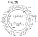
本発明の他の側面は、U形又は涙横断面を有するほぼドーナツ形状で形成された可撓性乳房受け部をもった搾乳器用の乳房シールドを有する。乳房受け部の向かい合った壁内に膨張可能なチャンバーが構成され、ドーナツ形状内に内部が構成され、この内部はお母さんの乳頭及びそれを取り囲む乳房を受け入れるようになっている。第1ポートが流体圧力源との連結のため膨張可能なチャンバーと連通し、第2ポートが圧力源との連結のため内部と連通する。ポートの一方又は両方はベース部に形成することができる。 Another aspect of the present invention includes a breast shield for a breast pump with a flexible breast receiver formed in a generally donut shape having a U-shaped or tear cross-section. An inflatable chamber is constructed in the opposing walls of the breast receptacle, and an interior is constructed in the donut shape, which interior is adapted to receive the mother's teat and the surrounding breast. A first port communicates with the inflatable chamber for connection with a fluid pressure source, and a second port communicates with the interior for connection with a pressure source. One or both of the ports can be formed in the base.
上記の実施形態の乳房受け部は有利には、平滑に湾曲した前方壁へ延び、次いで円周内側壁へ延びる円周外側壁を作る可撓性材料の単一片で形成される。側壁は互いに間隔を隔てて膨張チャンバーを形成する。前方壁は円周内側壁によって形成された、内部への開口を構成し、側壁はベース部に取り付けられた後方端壁構造体で終わる。後方端壁構造体はベース部に好ましくは取り外し可能に取り付けられる。これは、側壁を隔てることによって形成された開放リング形チャンネルである後方端壁構造体の使用によることがあり、ベース部はリング形チャンネルに受け入れられるリング形カラーを有し、それによって、乳房受け部はリング形カラーに密封可能に取り付けられる。他の方法は、リングを形成するように側壁を合わせることによって後方端壁構造体を形成させることにあり、ベース部はリング形縦穴を有し、リングがこのリング形縦穴に受け入れられ、それによって、乳房受け部をベース部に密封可能に取り付ける。 The breast receiver of the above embodiment is advantageously formed from a single piece of flexible material that creates a circumferential outer wall that extends to a smoothly curved front wall and then to a circumferential inner wall. The side walls form an expansion chamber spaced from each other. The front wall constitutes an opening to the inside formed by a circumferential inner side wall, the side wall ending with a rear end wall structure attached to the base part. The rear end wall structure is preferably removably attached to the base portion. This may be due to the use of a rear end wall structure that is an open ring shaped channel formed by separating the side walls, the base having a ring shaped collar that is received in the ring shaped channel, thereby providing a breast support. The portion is sealably attached to the ring-shaped collar. Another method consists in forming the rear end wall structure by aligning the side walls to form a ring, the base portion having a ring-shaped longitudinal hole, the ring being received in this ring-shaped longitudinal hole, thereby The breast receiving part is attached to the base part in a sealable manner.
全てではないが殆どの実施形態では、例えば、圧力源と第1ポートとの間に弁を更に設けることがある。弁は膨張可能なチャンネル内に所望な圧力レベルを維持するための第1位置と圧力レベルを解放するための第2位置とを有する。 In most but not all embodiments, for example, a valve may be further provided between the pressure source and the first port. The valve has a first position for maintaining a desired pressure level in the inflatable channel and a second position for releasing the pressure level.
本発明の更に他の側面では、搾乳器用の乳房シールドは互いに接合する左右部分で作られた剛性外シールド部を有する。外シールド部内に内シールド部が取り付けられ、内シールド部は乳房シールドに内側壁を形成し、乳頭を含む女性の乳房の少なくともいくらかを受け入れかつ乳房と実質的に気密接触してそれを取り囲むようになった内部を構成する。 In yet another aspect of the invention, a breast shield for a breast pump has a rigid outer shield made of left and right portions that join together. An inner shield is mounted within the outer shield, and the inner shield forms an inner wall on the breast shield to receive at least some of the woman's breast, including the nipple, and to surround and substantially hermetically contact the breast. Configure the inside.
内シールド部には可撓性領域が形成され、可撓性領域は乳房シールド内に受け入れられた乳房に対して移動できる。可撓性領域と外シールド部との間に第1空間が構成される。第1ポートが第1空間と連通して流体圧力源を第1空間に連結し、それによって、正の流体圧力の第1空間への付与により、空間を膨張させ、それによって可撓性領域を移動させる。第2ポートが内部と連通し、それによって、負圧源の内部への付与により、乳房を内部へ更に引き入れさせる。可撓性領域と外シールド部との間に、それぞれのポートをもった追加の空間を構成してもよく、各空間は、該空間が互いに独立に膨張収縮することができるように、互いに隔絶される。 A flexible region is formed in the inner shield, and the flexible region can move relative to the breast received in the breast shield. A first space is formed between the flexible region and the outer shield part. A first port communicates with the first space to couple a fluid pressure source to the first space, thereby inflating the space by applying positive fluid pressure to the first space, thereby causing the flexible region to Move. A second port communicates with the interior, thereby allowing the breast to be drawn further into the interior by application to the interior of the negative pressure source. Additional spaces with respective ports may be formed between the flexible region and the outer shield part, each space being isolated from each other so that the space can expand and contract independently of each other. Is done.
1つのこの様な空間は内部へ延びる可撓性領域の細長い部分である。細長い部分に対して外側に付与された負圧によって細長い部分に作用させることができ、それによって、内部から遠ざかり、それによって、内部に負圧を発生させるとともに、内部に搾り出された乳から負圧源を隔絶するのにも役立つ。
有利には、内シールド部の周りにクラムシェル構成で係合する上記の左右部分を設けるのがよい。左右部分は外シールド部から内シールド部の取り外しを可能にするように解放可能に連結される。
One such space is an elongated portion of a flexible region that extends into the interior. A negative pressure applied to the elongate portion can act on the elongate portion, thereby moving away from the interior, thereby creating a negative pressure inside and a negative pressure from milk squeezed inside. It also helps to isolate the pressure source.
Advantageously, the left and right portions described above are engaged around the inner shield portion in a clamshell configuration. The left and right portions are releasably connected to allow removal of the inner shield portion from the outer shield portion.
本発明の更に他の側面では、搾乳器の乳房シールドは、下流端で終わる管状部分へ延びる幅広の上流端を含む内じょうご形状を有する剛性外シールド部を含む。幅広の上流端は円周リムを有する。 In yet another aspect of the invention, the breast shield of the breast pump includes a rigid outer shield portion having an inner funnel shape that includes a wide upstream end that extends to a tubular portion ending at the downstream end. The wide upstream end has a circumferential rim.
ベース部はマウントを有し、外シールド部の下流端はこのマウント内に受け入れられる。ベース部には更に導管構造体が形成され、この導管構造体は、乳がベース部の中を流れる通路並びに第1流体通路及び第2流体通路を含む。 The base portion has a mount, and the downstream end of the outer shield portion is received in the mount. A conduit structure is further formed in the base portion, the conduit structure including a passage through which milk flows through the base portion, and a first fluid passage and a second fluid passage.
可撓性内シールド部は内じょうご形状とほぼ一致する形状を有し、そして外シールド部内に受け入れられる。可撓性内シールド部は、乳房シールドの内部を構成する内側壁を有し且つ乳頭及び乳房の少なくともいくらかを、前記可撓性内シールド部と密封接触して受け入れるようになった袋を含む。 The flexible inner shield portion has a shape that substantially matches the shape of the inner funnel and is received within the outer shield portion. The flexible inner shield includes a bag having an inner wall defining the interior of the breast shield and adapted to receive at least some of the nipple and breast in sealing contact with the flexible inner shield.
膨張可能な領域が可撓性内シールド部の袋と外シールド部との間に存在する。外シールド部には、膨張可能な領域と連通する流体孔が形成される。第1の流体通路は内部と連通し、第2流体通路は、外シールド部がベース部に取り付けられるとき流体孔と連通する。 An inflatable region exists between the bag of the flexible inner shield part and the outer shield part. A fluid hole communicating with the inflatable region is formed in the outer shield part. The first fluid passage communicates with the interior, and the second fluid passage communicates with the fluid hole when the outer shield portion is attached to the base portion.
その上、上記の可撓性内シールド部は、有利には、外シールド部のリムにスナップ嵌めする円周上流部分及び下流部分を有し、下流部分は管状部分の下流端のまわりに延び、それによって、管状部分のためのガスケット状構造体を形成し、管状部分をベース部とともに取り付けるのを容易にする。 In addition, the flexible inner shield part advantageously has a circumferential upstream part and a downstream part that snap fit into the rim of the outer shield part, the downstream part extending around the downstream end of the tubular part, Thereby, a gasket-like structure for the tubular part is formed, making it easy to attach the tubular part together with the base part.
上記の実施形態の乳房シールドは1つの形態では、乳頭及び乳房を内部内で更に下流に引く間欠的な負圧として第1出力を使用する。第2出力は袋を内部に対して内方に移動させる間欠的な正圧である。 The breast shield of the above embodiment, in one form, uses the first output as an intermittent negative pressure that pulls the nipple and breast further downstream in the interior. The second output is intermittent positive pressure that moves the bag inward relative to the interior.
添付図面と関連して示す種々の現在企画された実施形態の以下の詳細な説明を参照して、本発明は更に正しく認識され、またその特質及び利点が更に理解されよう。 The present invention will be more fully appreciated and its features and advantages will be better understood with reference to the following detailed description of various presently planned embodiments presented in connection with the accompanying drawings.
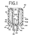
図1は本発明の乳房シールドの第1の実施形態を示す。乳房シールド40は、乳房受け部42と、乳房受け部42を受け入れる剛性ベース部材44と、で形成されている。ベース部材44は形状が円形であって、中央に下方に垂下した管状延長部46を有し、管状延長部は、大きな通路48と、小さい出口50と、を含み、出口50は乳房受け部42の内部へ延び、そしてその内部と連通している。ベース部材44は上面52及び外面54を有し、ベース部材44がこれらの面間に幾分円環体状即ちリング状の形状を形成する。リングの内側によって縦穴58が形成され、内部環状取付けリップ又はビード60が縦穴の中へ突出し、外部環状取付けリップ又はビード70(図2)がリングの外側に沿って延びている。乳房受け部42はこれらのリップ60、70でベース部材に取り付けられている。ベース部材44は、ベース部材の製造の際に余分な材料を除去するのに役立つ環状アンダーカット62を更に含む。
FIG. 1 shows a first embodiment of the breast shield of the present invention. The
図1のこの第1実施形態では、乳房受け部42は幾分ゴム状の全体的に可撓性の材料のものであり、主として、乳頭を、そのすぐ隣の乳房と一緒に取り囲むように設計されている。乳房受け部42は外側については、厚い側壁42Aを有し、この側壁は乳房受け部の入口へ延び、内部に沿って薄い側壁42Bを有する。厚い側壁42Aは乳房受け部がその全体的な形状を保持する構造を提供し、薄い側壁42Bは、後でもっと詳細に説明するように、もっと可撓性である。ビード70を受け入れる溝64が乳房受け部の外側壁42Aの内部底に沿って形成されている。薄い側壁42Bの内部底にも同様な溝が形成されてもよいし、或いは材料それ自体がビード60に簡単に嵌まる程の弾力性を有していてもよい。かくして、乳房受け部はこの方法でベース部材44に取り付けられることがわかるであろう。しかしながら、容易に理解されるように、乳房受け部42とベース部材は単一のピースとして整形されてもよいし、さもなければ、全体のまとまりとして組み立てられてもよい。
In this first embodiment of FIG. 1, the
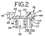
特に、今、図2に目を向けると、負圧又は第1圧力源(吸引)が管状延長部又は通路48に連結され、さもなければ管状延長部又は通路と連通しる。この第1圧力源はまた、ある適用では正圧を伝えてもよい。
In particular, looking now at FIG. 2, a negative pressure or first pressure source (suction) is connected to the tubular extension or
図示したように、小さい直径部分72bと連通している大きい直径部分72aからなるポート72による第2圧力源のための連結部がある。大きい直径部分72aは、第2圧力源と連通するチューブ77について、例えば、簡単な干渉嵌めによって連結体75との連結を容易にする。この第2圧力源は正圧(圧縮)でもよいし、あるいは、負圧でもよいし、これは、再び、適用と望まれる効果に完全に依存している。圧力は、空気又は他のガス、並びに、更に高温でも低温でもよい液体のようなどんな流体源でもよいことに気づくであろう。
As shown, there is a connection for a second pressure source by a
操作の仕方として、乳頭及びその直ぐそばでこれを取り囲む乳房領域が乳房受け部42の内部空間内に受け入れられる。第1の圧力源が負圧であり(48で)、第2圧力源が正圧である(72で)例示の状況を使用すると、負圧(吸引)が出口/通路50、48を経て付与される。これにより乳頭及び乳房に着く。圧縮圧力を第2圧力源からポート72を経て追加的に付与し、それにより、薄い内側壁42Bを乳房受け部の内部90へ拡張させる。それによって、この方法で乳がしぼられる。再び、ここに記載の発明の種々の実施形態で明らかにされるように、これらの圧力源は多くの方法及び組み合わせで選択され且つ適用される。例えば、第2圧力源は、第1吸引源が一定レベルに達した後にのみ最初は正圧であり、次いで、しかる後、負圧に転じる。第2圧力源は最初は負圧であり、かくして、第1圧力源の吸引によって乳頭が乳房受け部42の内部空間90に引き入れられると、乳房受け部42の内部空間90を拡張し、次いで、第2圧力源が正圧になって内部空間内の乳頭及び乳房を圧縮する。従って、多くの異なる圧力の組み合わせ、サイクル、及び適用が考えられる。
As a method of operation, a nipple and a breast region surrounding the nipple are received in the internal space of the
図1の実施形態では、絞り出された乳は最初縦穴58内に集まり、次いで出口50及び通路48を通過し、最後に瓶(この実施形態では図示されていないが、図4では、例えば84で)に、或いはその他の容器に集められる。搾乳器の流体制御(乳及び空気)の標準且つ周知のバルブ操作、搾乳器と一緒に通常使用される他の関連した搾乳器部品及び装置の詳細はここでは説明されていないが、そのようなものは例えば米国特許第4,857,051号に示されており、この様な他の詳細についてはこの特許を更に参照することができる。
In the embodiment of FIG. 1, the squeezed milk first collects in the
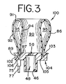
図3は多くの点で記載したばかりの乳房シールドと似た乳房シールドの第2の実施形態100を示す。可撓性の乳房受け部86がこの例ではほぼ一様な肉厚を有する。この乳房受け部86は、例えば、内部側壁94によって構成された内部空間90及び内部側壁94と外部側壁92との間にドーナツ状のチャンバー95を得るために折り返された単一の裁断片によって形成されるのがよい。これは、上記の側壁間に乳房受け部の平滑に湾曲した頂き移行部91を与える。この第2実施形態では、乳房受け部86の端87、89はベース部材104の頂面に形成された環状スロット又はチャンネル102内に取り付けられる。しかしながら、各端87、89がスロット102の周り少なくともずっとではなく接触しないで、チャンバー95の中へ延びる空間又は隙間を端間に形成することに気づくべきである。
FIG. 3 shows a
ベース部材104の底面105には、チューブ77及び連結体75を介して圧力流体、ここでは正圧を導くポート106が形成される。同じ番号は種々の実施形態の間の同じ部品及び要素に関することに気づくべきである。
A
内側壁94は内部空間90を構成し、内部空間は、内側壁が出口50の方に長手方向軸線に沿って移動する時半径方向に拡張する直径を有する。内部空間90内に挿入された乳房/乳頭は、乳頭が内部空間のこの輪郭の広がった領域内に配置されたことになる。内部空間90は出口50及びベース部材104の環状部46に形成された通路48と連通している。チャンバー95内に間欠的な正圧を、内部空間に負圧を付与するとき、内部空間のネックに受け入れられた乳房の乳頭領域並びに乳房それ自体は、乳房及び乳頭に向かったり遠ざかったりする乳房受け部の側壁の撓みによって揉まれ、乳頭は出口50をとおる真空によって内部空間90の中へリズミカルに引き入れられる。
The
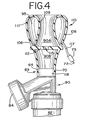
図4は、図3に示す実施形態のものと似た他の変形例を示す。本発明のこの第3実施形態では、肉厚は再びほぼ一様であるが、そうである必要はない。しかしながら、図3の方法で単一の片を折り曲げる代わりに、この乳房シールドは例えばその一体形状に形成することによって形成される。乳房受け部111は可撓性の内側壁109と外側壁108を有し、それらの側壁間にドーナツ状のチャンバー95を構成する。側壁108、109の「端」は隔壁部112と一体に接合され、それによって、乳房受け部111の内部空間を上部分90Aと下部分90Bに区切る。隔壁部はその中央に出口115を有する。
FIG. 4 shows another variation similar to that of the embodiment shown in FIG. In this third embodiment of the invention, the wall thickness is again substantially uniform, but this need not be the case. However, instead of folding a single piece in the manner of FIG. 3, the breast shield is formed, for example, by forming it in its unitary shape. The breast receiving part 111 has a flexible
上部分90Aは出口115と連通視、出口も内部空間の下部分80Bと連通している。下部分90Bは負圧源(真空)と連通している。チューブ117がこの第3実施形態の乳房受け部111のチャンバー95の中へ延び、そして側壁108に固定される。チューブ117が連結体75を経てチューブ77に連結され、チューブ77は正圧源のような他の圧力源に連結できる。再び、負圧源は、多分、工程のある時点で部分90A、90Bと連通するであろうけれども、これはサイクルの他の時点で部分90A、90Bに正圧を付与することを排除しない。同じように、負圧をチャンバー95に付与してもよい。負圧をチャンバー95に使用して部分90A、90B内に「真空」状態をつくることができる。連結体95はチャンバー95内の圧力を調整する圧力解放の一方向弁のような弁であってもよい。下部分90B内のカラー118は搾乳器80の一部であり、このカラー118に第3実施形態の乳房シールド110が取り付けられる。カラー118の外部は外部ビード70を有し、外部ビードは、乳房シールド110の下流端の首部89に形成された補足し合う溝64内に受け入れられる。もらろん、乳房シールドを搾乳器組立体の残部に取付け又は連結する他の手段、例えば、スナップ嵌め、螺合等を使用してもよい。
The
出口115を通過した乳は部分90Bからカラーの中へ流れ、そして内導管構造体を通って瓶84に至る。この実施形態では、手動ピストンポンプ82が乳房受け部の内部90Aと連通している負圧源として図示されており、このようなピストンポンプの詳細並びに搾乳器組立体は米国特許第4,857,051号で調べることができる。
The milk that has passed through the
前の実施形態と同じように、チャンバー95を、所望な方法で、即ち、乳房受け部の内部90A/90Bに周期的な吸引力を付与して、膨らませたり、萎ませたりする。乳房シールド110の乳房受け部の内部空間内に受け入れられた女性の乳房は内側壁109の撓み作用によって揉まれ、乳房から乳を絞り出す。
As in the previous embodiment, the
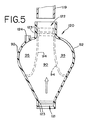
図5を参照すると、図3の実施形態を暗示する乳房シールドの更に他の実施形態が示されており、乳房シールドを形成するために記載された方法論も図1に示す実施形態にある程度まで適用できる。図5に示すように、乳房シールド120は、第1開口端121及び第2開口端又は首部122を有する可撓性の壁部材で形成される。第1開口端121の内部には一対の間隔を隔てたビード123が設けられている。乳房シールドは最初図5に実線で示す形状に成形することによって形成されるものである。外部側壁92は少なくとも一部(即ち外側にとどまる部分)が半剛性乃至剛性に作られる。
Referring to FIG. 5, yet another embodiment of a breast shield is shown that implies the embodiment of FIG. 3, and the methodology described to form the breast shield is also applied to some extent to the embodiment shown in FIG. it can. As shown in FIG. 5, the
図5の乳房シールドの構造は第1開口端121の可撓性壁部材の内部領域への反転を伴い、次いで可撓性壁部材を、図に示す太い矢印の方向(長手方向軸線)に沿って、第2開口端122の中へ引き入れる。ビード123は、反転工程により首部122を構成する側壁の内側に係合してそれを把持する。ビード123を受け入れるための溝を首部122の内側に設けてもよいことに気づくべきである。上記の工程の結果として形成された乳房受け部は、乳房及び乳頭を受け入れるための内部空間90を構成する内側壁94を有する単一の一体部材を有する。内側壁94と外側壁92が組合わさってドーナツ状のチャンバー95を形成する。圧力源をチャンバー95に付けるための連結体/チューブの取付け用のポート124が設けられている。図5の実施形態によって形成された乳房シールドは前に説明したカラー118と同様のカラー119に取り付けられる。
The structure of the breast shield of FIG. 5 involves the inversion of the first
図6は図1の実施形態と似た他の実施形態の乳房シールド130を示す。本発明のこの第4実施形態の乳房シールド130では、乳房受け部の内側に上部分又はチャンバー95Aと下部分又はチャンバー95Bを構成する内側リング状仕切り125が設けられている。上チャンバー95Aと下チャンバー95Bは互いに隔絶され、これらチャンバーはそれぞれのポート131、132を有している。ポート131、132の各々内に固定され且つそこから延びるチューブ117が示されており、連結体/弁75及び供給チューブ77がチューブ117に連結でき、正圧及び又は負圧流体をそれぞれのチャンバー95A、95Bに導く。各チャンバー95A、95B内の圧力は、一方のチャンバーが負圧を有し、他方のチャンバーが正圧を有するように、異なっている。他の例として、両方のチャンバーは、異なる量の正圧を有してもよい。再び、各チャンバー95A、95Bの圧力及びそのサイクル、並びに乳房受け部の内部空間90に付与される圧力を希望通りに選択し且つ調整することができる。前の図1の実施形態の操作と同じように、内側壁42Bの横断面が外側壁42Aの肉厚よりも薄いので、内側壁42Bはもっと可撓性であり、それにより、流体源が一方のチャンバー又は両方のチャンバーン95A、95Bに付与されるとき、内側壁を内部空間90の方に或いは内部空間から遠ざかるように撓ませる。内側壁42Bの撓みにより乳房及び乳頭が揉まれる。しかしながら、チャンバー95A、95B内部空間の2つの異なる圧力及びそれらの付与の効果、並びに内部空間90に付与される吸引を、例えば、授乳中赤ん坊の作用をもっと厳密に監視する方法で、独特に使うことができる。
FIG. 6 shows another
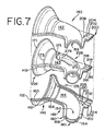
今図7及び8に目を向けると、本発明の他の実施形態が記載されている。図7で最も良く分かるように、第5実施形態の乳房シールド140は、第1半部142及び第2半部144を有する剛性の外シールド部と、それらの間に介在させたエラストマーの可撓性内シールド部143と、で構成される。外シールド部の第1及び第2半部142、144は互いに補足し合う虚像関係にあり、従って、図7に示す剛性シールドの下半部即ち第2半部144を幾分より詳細に説明する。
Turning now to FIGS. 7 and 8, another embodiment of the present invention is described. As best seen in FIG. 7, the
図から分かるように、剛性の外シールド142、144はじょうご部分146と一体の湾曲した管状部分148とで構成される。周囲フランジ150が外シールドの周辺を取り囲み、各半部142、144を互いにスナップ嵌めするのを容易にし、可撓性の内シールド143の補足し合うフランジ149をも捕捉する。変形例として、2つの半部を接合するためのクラムシェル効果をもたらすために、各半部を、単一の即ち共通のフランジ側が周知である方法で互いに一体に連結されるように成形してもよい。剛性の外シールドの前方端には、乳房が乳房シールド140内部空間に受け入れられるとき使用者の乳房に当接する内方に湾曲した平滑なリップ152が形成されている。変形例として、乳房とのより心地よい接触を行わせるために、軟質部の前端を前方に延長させてもよい。外シールドの他の(後方)端には環状カラー154が形成され、カラー154は、カラー、かくして乳房シールド140を、乳収集容器(図示せず)を含む搾乳器組立体の残部に連結するための雌ねじ山、スナップ嵌め手段、或いはある他の手段を備えるのがよい。
As can be seen, the rigid
各半部142、144には、半部のそれぞれの内壁156、158に形成された一連の長手方向に間隔を隔てた半径方向溝160、162、164、166が設けられている。半径方向溝は、2つの半部142、144が互いに取り付けられたとき湾曲座を形成する(図8参照)。座は、好ましくは、内シールド部143の外側に形成されたそれぞれのビード171、173、175、177を受け入れる半球横断面形状を有する。
Each
第1溝160はじょうご部分146に形成されたリップ152に隣接して位置する。第2溝162も、じょうご部分146と湾曲した管状部分との移行領域に隣接した直径の小さい端でじょうご部分146に配置される。第3溝164は湾曲した管状部分148の頂端178の近くに配置される。第4の最後の溝166は湾曲した管状部分148の下端180に位置する。半部142、144が接合されるとき、座の各々は内シールド部に一体に形成されたそれぞれのビード171、173、175、177を受け入れ、これは、内シールド部143を剛性外シールド半部内に固定し且つ位置決めするのに役立つ。
The
外シールドはまた管状部分148から突出する一体のポート付部分200を有する。ポート付部分200は第1、第2、第3圧力ポート202、204、206を備え、その各々は、それぞれ第1チャンネル208、第2チャンネル210、及び第3チャンネル212(チャンネル208、212だけを、説明のよりよい明瞭さのために)点線で示す)と連結される。各チャンネルは、まもなく以下で説明されるように乳房シールドの特定の圧力帯域に付与される流体圧力の導管を形成する。この実施形態の考えでは、各チャンネルは一方(又は両方)の半部142、144に形成され、内側に沿って開口する。エラストマーの内シールド部143は半部の内側に押しつけるように寸法決めされ、それによって、上記のチャンネルの開口内側を閉じ、それぞれの圧力帯域に至る導管構造を完成する。
The outer shield also has an integral ported
3つの圧力ポートは各半部142、144に等しく形成されそして形状が円筒形である。内シールド部143には3つのポート214、215、216が形成され、これらのポートは外半部のポート内に受け入れられる。内シールドのポート214、215、216の内端には出口218がある。これらの出口は外半部のチャンネルは連通する。空気又は他の流体圧力を導くための連結体/チューブはポート214、215、216で連結できる。明らかになるように、特定の帯域に付与される圧力は他の帯域とことなってもよいし同じであってもよい。各圧力帯域への導管は内側壁156、158で終わっている。勿論、帯域の数を増やしてもよいし、減らしてもよい。
Three pressure ports are formed equally in each
上記のように、乳房シールド140は内シールド部143を形成するエラストマーの可撓性部材を有する。内シールド部143は、円錐形部分226と、管状延長部分228とからなる第1及び第2半部、142、144とほぼ補足し合う形状を有する。内シールド部143の内側は女性の乳頭及び乳房を受け入れる内部空間90を構成する。
As described above, the
円錐形部分226には、ほぼ第1環状座160と第2環状座162との間に第1圧力帯域270が位置する。第1圧力帯域270より更に下流で、ほぼ第2環状座162と第3環状座164との間に第2圧力帯域が位置する。第3圧力帯域274が環状延長部分228に位置する。第1圧力帯域270は、23で内隆起領域の形態をなした膨張可能チャンバーによって構成される。これは、側壁構造に作られた薄い内部分(即ち、内部空間90へ面している)である。チャンネル/導管の端と整合した領域230への孔(図示せず)によって、チャンネル/導管208を介して運ばれた正圧が領域230に付与されるとき、第1圧力帯域270を構成しているこの側壁が、内方に、即ち図8に点線で示すように、内部空間90の中へ膨張する。圧力の解放により、側壁はその休止位置即ち元の位置に戻る。
In the
第2圧力帯域272が同様な方法で作られ、且つ作動する。第2圧力帯域272はチャンネル/導管210と連通している内シールド部143の領域231を有する。
The
この実施形態における内シールド部143はまた環状延長部228内部空間に一体に形成された一対の向かい合った窪み部分276を有する。各窪み部分276は触覚面として役立つ以外の何者でもなく、乳頭及び乳房は内部空間90内に付与された吸引作用で触覚面に軽く接する。しかしながら、窪み部分の外側と連通しているチャンネル/導管206のところの圧力源からの負圧により、窪み部分276の外側に働く負圧は窪み部分を外方に撓ませるのに役立つ。これは内部空間90内に負圧(吸引)を発生させ、これは真空源を隔絶するのにも役立つ。それによって、この変形形態ではチャンネル/導管212を経て運ばれる圧力により窪み部分276を膨らませたり萎ませたりすることができる。
The
図7及び8の上記の実施形態の操作では、女性の乳房を乳房シールド140の内部空間(チャンバー)90の中へ差し込み、例えば周辺152に内シールド部143の内側壁とともに気密シールが作られる。女性の乳房及び乳頭は、乳頭がほぼ可撓性の窪み部分276の間に受け入れられるように内部空間90の中へ延びる。1つの例として、正圧流体源(図示せず)を第1及び第2圧力ポート202、204に連結し、かくして帯域270、272に連結し、負圧を第3圧力帯域274への第3圧力ポート206に供給し(即ち、内部空間90内に吸引力を作る。)。吸引力が内部空間90に付与されると、正圧流体(例えば空気)が圧力帯域270、272に間欠的に付与される。正圧の付与により、これらの帯域でエラストマーの内シールド部143を、図8の点線で分かるように、内部空間90の中へドーナツ状に膨張させる。可撓性領域の内部空間90への膨張により、乳房の圧縮/減退を引き起し、そして乳房に揉み効果を生じさせる。負圧が内部空間90に間欠的に付与されると、可撓性の窪み部分276はその負圧の作用で乳房に対して周期的に撓み、接触したとき乳頭の刺激を引き起し、乳房からの乳の搾り出しを更に増すと考えられる。
7 and 8, the female breast is inserted into the interior space (chamber) 90 of the
各帯域において付与される圧力の速度及び量とともに、圧力付与のシーケンスを独立に確立して制御してもよい。これは、多分製造業者によって予め設定されるが、使用者によるいくらかの変化性も与えられるのがよい。利用される正圧及び負圧の両方について単一の圧力発生器(ポンプ)を使用してもよく、適当な圧力調整器及び弁が圧力帯域に付与される種々の圧力について採用される。真空/正圧発生用の一般的な装置、及び真空/圧力を搾乳器組立体及び乳房シールドに移送する関連したチューブは当業者において周知である。 The sequence of pressure application may be established and controlled independently with the speed and amount of pressure applied in each zone. This is probably preset by the manufacturer, but should also provide some variability by the user. A single pressure generator (pump) may be used for both the positive and negative pressure utilized, and appropriate pressure regulators and valves are employed for various pressures applied to the pressure zone. General equipment for generating vacuum / positive pressure and associated tubes for transferring vacuum / pressure to the breast pump assembly and breast shield are well known to those skilled in the art.
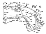
図9に目を向けると、本発明の第6の実施形態が示されている。この実施形態では、乳房シールドはツーピースの剛性外シールド部292A、292Bと、可撓性の内シールド部294とで形成されている。剛性外シールド部の第1ピースは主乳房シールドハウジング292Aであり、第2ピースは、ハウジング292Aに取りつけられ、乳房シールド290の掃除又は組立のために取り外すことができる蓋292Bである。変形例として、ハウジングはワンピースハウジングでも良くこの場合には、蓋部分は、一体のユニットを形成するために主本体部分に超音波溶接され、さもなければ固着される。
Turning to FIG. 9, a sixth embodiment of the present invention is shown. In this embodiment, the breast shield is formed of two-piece rigid
剛性ハウジング292Aは、使用者の乳房が主として受け入れられる領域と関連した、ハウジングの乳房受け部部分を構成する円筒体として形成された前部分を含む。円筒体の上流端は外方に湾曲したリップ又はリム296を有し、下即ち下流端298は、環状溝302を構成するように円筒体の内側壁面293から間隔を隔てていて、内方に突出した環状の出っ張り300を有する。環状溝302及びリップ296は、可撓性内シールド部の周りに延び、且つ溝302内に受け入れられる環状リップ又はフランジ346と、リップ296にスナップ嵌めする342及び344のところで可撓性内シールド部の前端によって構成された溝とによって可撓性内シールド部394を剛性外シールド部292A内にしっかりと固定し且つ位置決めする。
ハウジング292Aの後方(下流)部分は、前方ハウジング292Aの下端298から下方に垂下する円筒形チューブで構成された延長部分304からなる。延長部分304の一端には、乳収集瓶(図示せず)に取り付けるためのカラー310が一体に形成されている。カラー310は図示されているようにねじ山311を有してもよいし、或いは瓶との連結のためのスナップ嵌め機構等を備えてもよい。
The rear (downstream) portion of the
蓋292Bが、ハウジング292Aの場合半球形状又は他のそれに似た形状である楕円形領域330を覆い、乳房シールド290内にキャビティを構成する。包囲されたチャンネル316も蓋292Bの一部であり、ユニットの乳房受け部部分の内側に沿って延びるチャンネル320と連通している。蓋292Bの周囲には、蓋292Ba この領域で主ハウジング292Aの補足し合う肩にスナップ嵌めさせるアンダーカット319がある。チャンネル316は第1圧力ポート(図示せず)と連通し、その目的をすぐに説明する。蓋には第2圧力ポート326が形成され、この圧力ポートはキャビティ330と直接連通している。第1及び第2圧力ポートはそれぞれの加圧流体源に連結するようになっている。
A lid 292B covers the
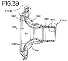
今、この実施形態の可撓性の内シールド部294に目を向けると、内シールド部には、前方部332、中間首部334及び後方(下流)部336が形成されている。前方部332は、後方端の溝302及びリップ300での取付けに関して前に説明した円筒部分からなり、そして、剛性シェルの円筒壁の形状と補足し合う。可撓性の無内シールド部294の前方部332の前方端は、溝又はリムを形成する内方に曲がった出っ張り344で終わる平滑に湾曲した移行部342を含む。これはハウジング292Aのリップ296を受け入れ、それによって、ハウジングのこの前方部で内シールド部294を取り付ける。
Turning now to the flexible
可撓性の内シールド部の中間首部334は前方部332及び後方部336と一体に形成され手いるので内シールド部全体は単一のピースである。中間首部334は可撓性のダイヤフラム348を構成する部分を含む。図9に示すように、ダイヤフラム348の休止位置は内シールド部294の中央領域にチャンネル349を作る。チャンネル349は内シールド部294の前方部332の内部空間90と連通し、また後方部336に構成される捕捉チャンバー領域350とも連通している。内シールド部294の後方部336は、ハウジング294Aからの剛性延長部304の円筒形状と補足し合う円筒形状に形成されている。捕捉チャンバー350の底には、ダックビル(フラップ)弁352の形態の弁機構がある。弁352はその頂点に、乳房から絞り出された乳を捕捉チャンバー350から導き出すためのポート又はスリット353を有する。
Since the
内シールド部の後方端は、可撓性の内シールド部の外側に形成された他のリップ又はフランジ362が内側壁に、剛性ハウジングの後方端に向かって形成された溝312に受け入れられることにより剛性ハウジング内に取り付けられる。内シールド部の後方端はこの溝312に簡単に嵌まり、内シールド部294の端に形成されたプル−タブ355はこの係合を容易にし、例えば掃除のための、係合外しも容易にする。
The rear end of the inner shield part is received by a
前に述べたように、可撓性内シールド部の前方端332は内部空間90内に女性の乳房を受け入れ、乳頭が可撓性ダイヤフラム348まで突出し、そしておそらく狭いチャンネル349の中へ突出する。正圧流体が第1圧力ポート(再び、図示せず)に付与されたとき、その圧力はチャンネル316に、それ故にチャンネル320に伝えられ、そして圧力はリップ296と可撓性内シールド部342との間の隙間364に入る。流体の圧力により、剛性ハウジング292Aの内側壁293に位置する可撓性内シールド部を点線で示すように、内部空間90に向かって膨張させ、或いは突出させる。内シールド部294の内向きの撓みは揉み作用及び圧縮接触を乳房及び乳頭に与える。それを、シールドを所定の乳房に「合う大きさにする」手段としても使用することができる。
As previously mentioned, the
上で分かるように、内シールド部294の可撓性ダイヤフラム334と蓋292Bは、第2圧力ポート326と連通している包囲されたキャビティ330を構成する。第2圧力ポート329は、この実施形態では好ましくは、負圧流体源である流体源(図示せず)と連通している。
As can be seen above, the
負圧流体がキャビティに伝えられると、可撓性ダイヤフラム348は蓋292Bに向かって移動され、(乳頭が最初接触していたならば)乳房の乳頭との接触を絶つ。かくして、間欠的な負圧がキャビティ330内部空間に生じ、可撓性ダイヤフラム348はその負圧を内部空間90内部空間に吸引として伝え、それによって内部空間内の乳房及び乳頭を引く。乳の搾り出しを更に容易にする乳頭及び乳房の揉み作用も、キャビティ内部空間の真空の解放でダイヤフラムがその休止位置に戻るときに行われる。かくして、ダイヤフラムは、(内部空間90に付与される)真空源を、絞り出される乳、並びに乳房によって運ばれるかもしれないその他のもの(バクテリヤ)から分離するのに役立つ。絞られた乳はチャンネル349を通って捕捉チャンバー350へ排出され、弁352は、ダイヤフラムがその休止位置に戻るときに発生されるような、正圧により(又は負圧の解放により)収集瓶(図示せず)への乳の排出を制御する。
As the negative pressure fluid is transferred to the cavity, the
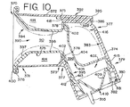
図10に注目すると、本発明の乳房シールド370のダイヤフラムの第7実施形態が示されている。この実施形態では、乳房シールド370は一体の剛性外シールド部392と、可撓性の内シールド部394と、からなる。剛性外シールド部392は、中空円筒体372で構成された第1部分と、下方に垂下した管状延長部374で構成された第2部分と、を含む。縁と歌い372の頂端即ち前方端371は外方に延びたリップ又はフランジ376を含む。円筒体372の下端373は、第1部分と第2部分が接合する箇所で中空円筒体372の内側壁面375から内方に延びる、無い方に突出した出っ張り又はフランジ378を含む。管状延長部374の下端379は収集瓶(図示せず)との取付け用のカラー380を含む。カラー380の内側面381はねじ山382を備えるか、周知のように、スナップ嵌め手段(図示せず)のような瓶のためのある他の取付け機構を備えるかのいずれでもよい。
Turning attention to FIG. 10, a seventh embodiment of the
圧力源との連結のための部分385が、第1部分372と第2部分374が互いに接合する箇所で乳房シールド370の頂領域に一体に取り付けられている。図10Aで分かるように、この部分385は、加圧流体を乳房シールドに与える内ポート386、388を備える。ポート386、388の機能を、内シールド部394の説明の後に以下で詳細に説明する。
A
内シールド部394は上じょうご状部分390と、中間首部396と、下円筒部分395と、で構成されている。上じょうご状部分390は、互いに一体に接合された円錐部397と管状部398とで構成されている。円錐部397の外即ち前方周縁は、上じょうご状部分397を中空円筒体にこの領域で固着するように、管状リップ376にスナップ嵌めする内方に曲げた縁又はリム400によって構成される。同様に、中間首部396は、外シールド部392の内部に形成された内方に突出した環状出っ張り378に嵌まる環状U形スターラップ402を備えている。
The
中間首部396は内シールド部394の中央部分を貫いて延びるチャンネル405を構成する可撓性ダイヤフラム404を更に含む。チャンネル405は、じょうご状部分397及び管状部分398の内部の領域によって構成された内部空間90と連通している。狭いチャンネル405も、内シールド部394の下円筒部分395を構成する捕捉チャンバー407と連通している。捕捉チャンバー407はチャンバーの底に一体に形成された弁409を含む。弁409は絞られた乳を捕捉チャンバー407に通すためのポート410を有し、そして図9に示す実施形態に設けられた弁と実質的に似て構成され、従って弁の更なる詳細を提供する必要はない。
The
捕捉チャンバー407の外部には環状突出部412があり、これは、取付けカラー380より上で延長部374の内側壁に形成された環状溝415内に差し込む小さいナブ413によって構成されている。ナブ413と溝415は一緒になって内シールド部394野下円筒部分395を外シールド部392内にしっかりと保持する。
Outside the
内シールド部394が外シールド部392内に挿入されたとき、乳房シールドの前方部において内シールド部と外シールド部との間に第1環状キャビティ414が形成され、内シールド部394のダイヤフラム404と延長部の上端377との間に第2キャビティ416が形成される。上述したように、ポート部分385は内ポート386、388を備えている。ポート386は出口418で第1キャビティ414と連通し、ポート388は連結用導管389を介して第2キャビティ416と連通している。第2ポートは負圧流体源に連結され、第1ポート386は正圧流体源に連結されるのがよい。変形例として、両方が正圧流体源を備えてもよい。その上、これは上記の実施形態全体に種々適用し、第1キャビティにゲル又は流体(水又は空気)を充填し、使用に先立って、又は使用中ゲル又は流体を加温度してもよい。
When the
第1キャビティ414に正圧流体が与えられるとき、内シールド部394のじょうご状部分397及び管状部398は点線で示すように内部空間90に向かって膨張する。変形例として、第1キャビティ414に負圧流体があたえられたら、この同じ部分は中空円筒体372の内壁面375に向かって吸引される。いずれの適用においても、内部空間90内に受け入れられた女性の乳房が上じょうご状部分の撓み運動によって揉まれる。
When positive pressure fluid is applied to the
第2チャンバー416には負圧が与えられ、従って可撓性の内シールド部394のダイヤフラム404は、図10に点線で示すように、延長部374の内面383に向かって吸引される。これにより、負圧を内部空間90内へ伝え、図9の実施形態について上述したように、真空機構を乳房シールドからもう一度隔絶するのに役立つ。乳房の乳頭は、上述したように、撓み中ダイヤフラム404によって更に揉まれる。絞られた乳は狭いチャンネル404を通って捕捉チャンバー407に入り、次いで弁409を介して、カラー380に取り付けられた瓶(図示せず)に導かれる。
A negative pressure is applied to the
図11は本発明の乳房シールド420の第8実施形態を示す。この実施形態では、剛性外シールド部423はじょうご状である第1部分を有し、この第1部分は円筒壁部分430の前方端424に一体に連結された前円錐部分422からなる。リム421が円錐部分422の前の周囲を取り囲む。円筒壁部分430の後方端426は直径が減じてノズル又は連結体部分432を形成する。下方に傾斜した管状部分434で構成された、剛性外シールド部の第2部分が円筒壁部分430と交差している。連結体部分432は環状ポンプカラーで終わっており、この環状カラーは、正圧と負圧の両方を提供する事が出来る流体源に乳房シールドを連結する。
FIG. 11 shows an eighth embodiment of the
外シールド部423は円筒部分430の前方端424から環状ポンプカラー436まで延びる内仕切り壁438を更に含む。内仕切り壁438は、下方に傾斜した管状部分434の内部中心に位置する壁440を更に有し、この壁は絞られた乳が、外シールド部423内に更に構成されたチャンネル448を上方に通るのを抑えるスプラッシュ壁として役立つ。円筒部分430の前方端にはスタブ壁442があり、これは、内仕切り壁438とともに第1圧力チャンネル444を構成し、この圧力チャンネルは内シールド部447と外シールド部の内側壁との間に構成された内空間446と連通する出口445を有する。上記のように、分離壁440は管状部分434の内側壁とともに、第2圧力チャンネル448を構成する。第1圧力チャンネル444及び第2圧力チャンネル448は共通してノズル部分432のカラー436で終わっている。
The
可撓性内シールド部447もほぼじょうご状をなし、そして外シールド部423の前円錐部分422と捕捉し合い、且つその円錐部分内に受け入れられた前円錐部分450を有する。内シールド部447も外シールド部423の円筒部分430内に受け入れられた管状部分451を有する。円錐部分450及び管状部分451は女性の乳房をうけいれるための内部空間90を構成する。
The flexible
円錐部分450はリム421にスナップ嵌めする環状溝454を有し、それによって、内シールド部447を乳房シールドの前端で、外シールド部423に固着する。管状部分451は円錐部分450に一体に接合された第1端と、スプラッシュ壁440の上流位置で終わる浮動の第2端456と、を有する。女性の乳房は内部空間90の部分内に受け入れられ、乳頭は管状部分451の中へ延びる。
The
管状部分451は、それが逆テーパーするように形成された肉厚を有し、逆テーパーは、半径方向横断面厚さが前端から456で指示した後方端まで増していることを意味する。テーパーした肉厚は外シールド部の円筒部分430の内面435と内シールド部の管状部分450との間にテーパーした環状空間457を形成する。テーパーした環状空間457はチャンバー446と連通し、また内シールド部の端456の近くに位置した排気(通気)ポート458と連通している。排気ポート458は、以下で説明するように、周りの大気に流体を放出する。
作動中、環状ポンプカラー436は複流体圧力源(図示せず)に連結し、第1圧力チャンネル444は正圧流体を、テーパーした環状空間457に入る前に、チャンネルを介してチャンバー446に伝える。テーパーした環状空間457に入る流体の初期の正圧上昇は先ず管状部分451のテーパー壁の最も薄い部分に接触して、壁を内部空間90に向かって膨張させる。これは、管状部分451に沿って前から後ろに移動する波を形成させることになる。テーパーした環状空間457に付与された急速間欠の不連続な正圧流体は、図11に点線で示すように、加圧流体の各連続する間欠バーストによって形成された1つのローリング波又は一連のローリング波形態を生じさせる。内シールド部447の管状部分451の肉厚が後方端456に向かって増しているので、一連のドーナツ波は大きさ(高さ)が徐々に減少する。流体が間欠的に供給されるので、テーパーに沿う壁の内向きの膨張程度はカスケード又はさざ波の仕方で減少する。正圧は第2端456で、排気ポート458から大気に放出される。
In operation, the
ポンプカラー436に連結された負圧流体源(図示せず)は、分離壁440の周りに連通される第2圧力チャンネル448内の負圧又は真空を内部空間90に伝える。負圧は乳房を周期的に引く。絞られた乳は上述の方法で下方に傾斜した管状部分434の下端に受け入れられた収集瓶(図示せず)に流入する。
A negative pressure fluid source (not shown) connected to the
図12に注目すると、本発明の乳房シールド460の第9実施形態が示されている。この実施形態では、剛性外シールド部461は2つの部分を有し、その一方はベースプレート464を含む取付けベース463であり、取付けベース463の前方端465は片寄ったU形リング474を有する。傾斜した管状延長部467が、(短い円筒体をなす)側壁472によって構成された導管462と交差する。管状延長部467は下端470を有し、該下端は、これを取り囲むフランジ471を有する。管状延長部467の内部468の中へ突出する下方に垂下した分離壁483があり、この分離壁は1例として、図11に関して前に説明したように、スプラッシュ壁として役立つ。
Turning attention to FIG. 12, a ninth embodiment of the
U形リング474はねじ山付内面482を有する外壁480を含み、ねじ山付内面482は、図12のこの剛性外シールド部の他の部分を受ける。部分490の閉鎖ベース487は、相手のねじ山473を介して、ねじ嵌めによりリング474内に嵌まる。
関節部490は袋状構造物からなる。関節部は女性の乳房を内側壁488にそって受け入れるための内部空間90を構成するほぼ二重壁の裁頭円錐形状を有する。部品490の外側壁491は前即ち前方丸端500に沿って内側壁488と平滑に接合する。関節部490は実質的に剛性プラスチック材料で形成され、且つ一体のものとして形成されるのがよい。明らかなように、関節部490は、ポート498のところを除いて、閉鎖された内チャンバー499を構成する。
The
関節部は外側に開口した大V形チャンネル492を更に有し、内側壁488は、大チャンネルの各側に1つずつ、2つの横方向に間隔を隔てた内側に開口した小V形チャンネル494、496を有する。これらの大小チャンネルは関節部の周囲に延びる。圧力ポート498は正圧流体源を内部キャビティ499に連通させる。これは、例えば、温水、液体ゲル等でよいが、単なる空気ではない。
The joint further includes a large V-shaped
可撓性内シールド部品485が関節部490を取り囲み、内シールド部品485の上部分502は関節部の前端の頂丸縁500に折り曲げられる。内シールド部品485の弾性の性質は内シールド部品を内側壁488の内面にしっかりと保持する。可撓性内シールド部品485は関節部とほぼ一致するように形成され、かつ下流端486を有する。下流端はU形リング474の内側に位置する。
A flexible
使用中、負圧流体源(図示せず)は剛性外シールド部品のベースプレート464に導管462のところで取り付けられ、それによって、真空をスプラッシュ壁483と管状延長部467の側壁との間のチャンネルを介して内部空間90へ導く。例えば、正圧流体源がポート498を介して関節部490の内部キャビティ499につながれる。大チャンネル492はヒンジとして作用し、それによって関節部490の前端500を点線で示すように外方に撓ませる。小チャンネル494、496は、側壁のいくらかの膨張を行わせることによって大チャンネルを中心とする袋状構造物の撓みを容易にする。関節部の内チャンバー499内の間欠的な正圧は、関節部490、それ故に内シールド部品485の周期的な撓み運動を生じさせ、これは内部空間90内に受け入れられた乳房に周期的な揉み作用を行い、それによって乳房から乳の絞りを助長する。同様な方法で、462に負圧を使用して周期的な撓み運動を発生させてもよい。乳は次いで真空により分離壁に向かって伝えられ、次いで管状部材467を通して下方に伝えられ、ちちは、周知のようにフランジ471に連結された瓶(図示せず)に集められる。変形例では、圧力源を小チャンネル494、496と連結してもよい。これが、例えば、正圧源であれば、小チャンネル494、496とこれらのチャンネルの上に位置する可撓性内シールド部品485との間に形成されたチャンバーを膨張させる。これにより、同様に、前端500を大チャンバー492によって形成されたヒンジで外方に撓ませる。これらのチャンネル/チャンバーに付与された負圧は内方曲げを引き起こす。
In use, a negative pressure fluid source (not shown) is attached to the rigid outer shield
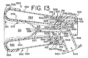
図13は本発明の乳房シールド505の第10実施形態を示す。図12の実施形態と似たこの実施形態では、2つの部品で作られた外シールド部があり、そのうちの一方は下方に傾斜した管状部材598を有するベース部506である。管状部材598の下端600は、周知のように中間カラー部材(図示せず)を使用して瓶に連結されるフランジ602を備えている。
FIG. 13 shows a tenth embodiment of the
ベース部506の前端508が側壁514によって形成され、側壁の内面515にはねじ山が切ってあって、後述する外シールド部の他の部分550を受け入れる。内部肩が516に設けられている。側壁514と肩516との間に、流体連通部材として機能する環状可動U形カラー525が受け入れられる。カラー525は肩に当たる環状ベース部材527と壁514の内部から間隔を隔てた、上方に突出した内リング529とで構成されている。
A
外シールド部の他の部分550の内側に、可撓性内シールド部570と共同して中央チャンバー又は通路531が形成される。環状カラー525の底(後方)面に沿うアンダーカット533は、すぐに説明するように、ポート522に形成された出口521を通る流体(空気)流のための導管又は通路を形成し、この連通は可撓性内シールド部570の追加の構造物と組み合わせて完成される。
A central chamber or
外シールド部のベース部506は、また片寄せられたアンダーカット520で終わるポート518を含み、それによって、ポート518の出口を形成する。この出口はこの実施形態では、環状であり、環状部材598内の広いチャンネル部544へ延びている。ポート518のためのこの出口/チャンネルは、取り外し可能なカラー525がベース部506内に受け入れられるとき、取り外し可能なカラー525の底(後部)に形成された環状チャンネル535と流体連通する。チャンネル535は、カラー525の前方側で他の環状チャンネル537に通じた貫通穴536の形態の1つ又はそれ以上の内部導管を有する。
The
すぐに明らかになるように、撓む能力を有する半剛性材料で形成された二重壁部材550が図13のこの実施形態の乳房受け部の外シールド部を完成している。部材550は外側壁552、内側壁554、頂き平滑移行面556、及び平らなベース面560を更に含むネジ山付後方環状首部558で構成される。平らなベース面560は、取り外し可能なカラー525のチャンネル537と連通した吸気開口562を有する。かくして、部材550の側壁内には、ベース部506に形成された通路518と流体連通した内部チャンバー564が構成される。
As will be readily apparent, a
乳房シールドは、部材550内に配置された可撓性内シールド部570を更に含む。内シールド部570は収縮したステム582の中へ延びる広い頂(即ち前方)端577を有する。上端577は外方に、次いで下方に突出した湾曲部分580を有する。図13に示すように、湾曲部分580は、外シールド部550の頂移行面556の周りにフック止め(スナップ嵌め)しており、それにより、内シールド部を乳房シールドのこの前領域で外シールド部に取り付ける。
The breast shield further includes a flexible
ディスク形ベース590がステム582の底端として一体に形成されている。ディスク形ベースはベース部506に形成された他の肩523に当たっている底面592を有する。取り外し可能なカラー525の底面に形成されたアンダーカット533とベース部材590の頂面594との間の距離は、内シールド部の下端が、チャンバー531内の正圧(又は負圧)及び又は604で付与されるような、環状部材598内の負圧のもとに肩523に効果的に着座するような距離である。ディスク形ベース即ちディスク590の横(半径)寸法形状もポート522に通じる通路533を得るように選択される。
A disk-shaped
図13が更に示すように、内側壁はその上に重なる可撓性シールド部材とともに女性の乳房を受け入れるための内部空間90を形成する。内部空間588が、ディスク590の開口595で終わるステム582に沿う可撓性シールドによって更に構成される。その開口595は環状部材598の内部604と流体連通している。ディスクには、外シールド部内に可撓性シールド部を取り付けるのを容易にするリング状プル596が形成されていることに気づくであろう。即ち、外シールド部550をカラー525と組みたてる。次いで、ステム582をプル596を介してカラーの中に引き通して、可撓性シールド部570を外シールド部550に取り付ける。次いでこのユニットになった組立体をベース部506に螺合する。
As further shown in FIG. 13, the inner wall forms an
女性の乳房の乳頭はステム582の上端で内部領域588の前に受け入れられる。しかしながら、乳頭がそれ以上遠くに達する必要はない。気づくように、内部領域588は、一端が内部空間90と連通し、底端579が内部604と連通している。作動中、正圧流体源(図示せず)及び負圧流体源(図示せず)は外シールド部のポート518(正圧)及びポート522(負圧)にそれぞれ連結され且つそれらとそれぞれ連通している。ポート518からの正圧は、部材550の内部チャンバー564が正圧流体で満たされ且つ拡張するように、開口562を通して伝えられる。内部チャンバー564の充填により、側壁554を内部空間90の中へ僅かに撓ませる。
The female breast nipple is received at the top of the
ポート522からの負圧は外シールド部の内側壁554とステム582を構成する内シールド側壁との組み合わせによって形成された内部チャンバー531と連通する。これにより、チャンバー531を収縮させて領域588を拡げる。これは、内部空間90内に負圧(吸引)を伝え、これは乳房及び乳頭を引くのに役立つ。チャンバー531に付与された負圧が解放されると、チャンバーはその休止位置に戻り、乳房/乳頭を潜在的に収縮させ或いはやさしく揉む。乳房受け部の前方部分及び後方部分のこの運動は、所望な方法で時間合わせすることができる、乳房及び乳頭の揉み操作を引き起す。
The negative pressure from the
本発明の第11の実施形態610を図14に示す。この実施形態では、外シールド部は再度2つの部分、即ち剛性ベース部611と取り外し可能な剛性前方部分638とで構成される。ベース部611は下方に傾斜した管状部材612を有し、管状部材612は、U形チャンバー615を構成する環状U形リング614で終わる前方部分613を有する。
後方部分624は、乳収集瓶(図示せず)に取り付けるための雌ねじ626を有する環状取付けカラー625で終わっている。
An eleventh embodiment 610 of the present invention is shown in FIG. In this embodiment, the outer shield is again comprised of two parts: a rigid base 611 and a removable rigid front part 638. The base 611 has a downwardly inclined
The
一端が出口629で終わっている導管又はポート635が円筒側壁構造物628によって構成されている。ポート635の他端はポンプカラー632に通じている。ポンプカラー632は、周知のように、手動搾乳器(図示せず)のような搾乳器との連結用の雌ねじ633を有している。
A conduit or
U形リング614は、外壁616、内壁620及び相互連結用ベース壁619で構成されている、(ベース壁には、1つの領域に出口629が構成されている)。外壁616は平滑な内面618を有し、内壁620は平らな傾斜面622を有している。
The
外シールド部の前方部分638は側壁639で構成された剛性バレル形部分で構成され、側壁639はU形リング614の外壁616の内面618とプレス嵌めする前方端640を有する。バレル部分639はボウル即ち円錐形部分644に領域642で一体に接合される。部分639と円錐部分644との間の移行箇所は内方に突出した突出部646を形成し、この突出部は外部に面した溝648を構成する。ボウル部分の前方端は周縁面653を有する。
The front portion 638 of the outer shield portion is comprised of a rigid barrel-shaped portion comprised of a
乳房シールド610はまた外シールド部内に受け入れられた可撓性内シールド部656を有する。内シールド部656は側壁674によって構成された円筒部分で構成され、側壁674はバレル形側壁639から間隔を隔てた関係にあり、それによって、キャビティ又はチャンバー670を形成する。円筒部分の側壁674の後方端658には、U形チャンネル615内に受け入れられたベース出っ張り662が形成されている。ベース出っ張り662は、U形リング614の傾斜内壁620に及び側壁639の内面に摩擦嵌めされる傾斜壁664を有する。ベース出っ張り662には貫通穴としてポート637が形成されている。内シールド部656の側壁674によって構成された円筒部分の前方端660は内向きの突出部646に受け入れられる溝665を備えている。これは圧嵌めを形成し、且つ内シールド部656をこの領域に位置決めする。内シールド部656の円筒部分は、下方に傾斜した管状部材612の内部672と連通する内部空間90を構成する。内シールド部656のじょうご部分667はボウル部分644の内面にぴったりと接触している。じょうご部分667は、ボウル部分644の周縁面653に受け入れられる、内シールド部656をこの領域で取り付けるための外方に延びたリップ669で終わっている前方端668を有する。
Breast shield 610 also has a flexible
可撓性内シールド部656の側壁674の外側に面した面はまた外側に延びるビード680を有し、該ビードはもう1つのビード680から横方向に間隔を隔てている。ビードの機能を以下で説明する。内シールド部のじょうご部分667はまた女性の乳房を受け入れる内部空間90の一部を形成する。乳房の乳頭は、じょうご部分667内に受け入れられたとき、環状突出部646を超えて延びる。
The outwardly facing surface of the
作動中、真空源(図示せず)をポンプカラー632に、或いはチューブを介してポート635に連結して負圧流体をチャンバー670に伝える。第1ビード678及び第2ビード680は、一連の遮断として機能する。キャビティ670に最初に付与された負圧により、可撓性内シールド部の側壁674を、剛性の外シールド部側壁639に向かって吸引させる。これは図に点線でしめされており、第1ビード678が側壁639の内面に接触する。真空が高まると、次いで、第2ビード680が側壁639の内面に接触する。この結果、内チャンバー90の徐々の拡張が乳房受け部の前から後ろに及ぶ。これを負圧の解放で間欠的に行うことができ、或いは正圧の付与で交互に行い、それによってチャンバー670を拡張させ且つ又その中の乳房/乳頭を圧縮することができる。
In operation, a vacuum source (not shown) is connected to the
本発明に従って作られた第12実施形態702を図15に示す。分かるように、剛性外シールド部はじょうごのように構成され、円筒部分696に一体に連結された円錐部分686を有し、円筒部分696は、形状がほぼ管状であるベース部708で終わっている。円錐部分の第1端688は直立リム又はリップ692によって構成される。傾斜管状部材708の底端710は、周知のように、カラー(図示せず)を介して乳収集瓶に底端を取付けるためのリング712を有する。管状部分の内部は714で指示され、そして側壁707の内面に取り付けられた下方に垂下した分離壁又はスプラッシュ壁716を有する。側壁707は圧力チャンネル又はポート706を更に構成する。前の実施形態におけるように、管状部分の内部714はポート706を介して負圧源(図示せず)と連通している。
A
側壁696によって構成された円筒部分はまた側壁内面698に形成された内管状肩700を有する。肩700はホルダー部材726を受ける。ホルダー部材726は、管状棚700で受けられる底端729を有する内側壁728と、短い外壁730と、を有し、この外壁は、リップ692の端面694に当接する外側に延びる周囲リム又は棚732を有する。短い壁730の底端734は円錐部分686の内側で肩689まで延びている。壁728と730との間に環状窪み738が延びている。
The cylindrical portion defined by the
ドーナツ形ゲルパック(或いは空気又は水若しくは発泡体を入れたパック)が窪み738内に受け入れられる。ドーナツ形ゲルパック740は、すぐに説明するように、可撓性内シールド部735によって窪み内に保持される。
A doughnut-shaped gel pack (or a pack containing air or water or foam) is received in the
可撓性内シールド部735は、湾曲部742へ延び且つ外側壁743で終わっている内側壁741で構成される。可撓性内シールド部735は一体物として作られる。内側壁は、後ろから前に移動するにつれて肉厚が僅かに増大していることに気づくであろう。湾曲部742は乳房受け部への開口を形成する。可撓性内シールド部735は、ゲルパック740を窪み738内に保持して、ホルダー部材726及び剛性外シールド部に嵌まる。
The flexible inner shield part 735 is composed of an
もう一度、可撓性内シールド部は女性の乳房を受け入れる内部空間90を構成する。内部空間90はポート706を介して負圧源と流体連通している。可撓性内シールド部の後(下流)端は側壁696の内面に密着する。
Once again, the flexible inner shield defines an
ホルダー部材726はここでは剛性片として示されている。しかしながら、ホルダー部材は、その形状を支持し且つゲルパックを位置決めするに十分堅く、しかし圧力でいくらか移動可能にするのに十分撓み得る半可撓性材料で形成されるのがよい。その圧力はホルダー部材726と剛性外シールド部の円錐部分686との間に構成されたチャンバー725内に付与されるだろう。その圧力は希望に応じて正圧でもよいし負圧でもよいし、側壁686に設けられたポート(図示せず)から付与されるはずである。
正圧のような圧力が、ゲルパックの置かれているキャビティ内にも与えられ、或いはゲルパックそれ自体にも与えられる。可撓性シールド部の両端が適当に固定され、可撓性部材の壁の湾曲領域742が適当に薄くされると、ゲルパック部分を、点線で示すように膨張収縮するようにすることができる。簡単な中空チャンバーでのゲルパック740の利点は、ゲルパックを温かくしたり冷たくしたりすることができ、温度変化の追加的な治療効果を乳房シールドに加えることである。
A pressure, such as positive pressure, can be applied in the cavity where the gel pack is located, or it can be applied to the gel pack itself. When both ends of the flexible shield portion are appropriately fixed and the
本発明の第13実施形態750を図16に示す。もう一度、外シールド部は2つの剛性片で構成される。一方は下方に傾斜した管状部材759を有するベース部758である。下方に傾斜した管状部材759の底端760は、周知のように、乳収集瓶(図示せず)との取り付け用の雌ねじ763を有する環状取付けカラー762を含む。ベース部758の前方端には短い円筒部752がある。ベース部758には内側壁766と外側壁767によってポート770が構成される。そのポート770は768に出口を有する。769で指示した、側壁767の前方外側には、短い円筒部752から内方に間隔を隔てた側壁785と関連して雄ねじが設けられており、側壁769、785は一緒になって連続取付けカラーを形成する。このカラーは、ほぼ円筒カップ788の形態をなした、剛性外シールド部の他の片を受ける。カップ788は剛性外ベース部の後方端790の環状カラーとのねじ連結部を有する。剛性外シールド部のカップ788及びベース部758には可撓性内部材784が取り付けられている。内部材784の内部構造をもっと詳細に説明する。しかしながら、一般的には、それは剛性連結用リング800に固定された周縁795を有する。繋ぎリング800は外ビード804を有し、外ビードは、カップ788の前方端に形成されたそれと捕捉し合う形状の溝796に受け入れられる。この連結は可撓性内部材、即ち内シールド部784を乳房受け部の前方端に位置決めし且つ取り付けるのに役立つ。可撓性内シールド部784の後方(下流)端は、短い円筒部752の外側に嵌まるカラー状構造体765で終わる。フランジ又はリム771がカラー構造体765の開口から延び、カップ788の内側に延びるフランジ7に当接する。これは可撓性内シールド部を更に固定し且つ位置決めするのに役立つ。
A
図16のこの実施形態では可撓性内シールド部のための二重壁構造体が設けられている。しかしながら、正圧/負圧を受けるべき単一のチャンバーを構成するのではなく、この可撓性内シールド部は、図16Aからも最も良く見られ且つ理解される3部分の部材に形成される。内シールド部784は3つの別々の内側壁780、782、785によって形成され、これら内側壁は一緒になって単一内シールド部を形成する。側壁788の内面798と各内側壁780、782、785の内面との間の空間は3つのチャンバーを形成し、チャンバーは互いに連通していてもよいし、或いは完全に別々なチャンバー806、808、810であってもよい。そのように別々の場合には、各チャンバーの独立の圧力調整を可能にするために、ポート770に追加のポートを設けてもよい。
In this embodiment of FIG. 16, a double wall structure for the flexible inner shield is provided. However, rather than constructing a single chamber to receive positive / negative pressure, this flexible inner shield is formed into a three-part member that is best seen and understood from FIG. 16A. .
休止状態、即ち例えば、チャンバー806、808、810が負圧下に内部空間状態では、3部分可撓性内シールド部784によって作られた乳房受け部は図16及び16Aに示す通りになる。これは、収縮したステム部812へ延びる短い円錐前部になる。かくして、内部空間90は初期にはそのように構成される。ステム通路812は管状部材758の内部815と流体連通している。
In a resting state, for example, the
作動中、負圧流体源が圧力ポート770に連結され、それによって、剛性外部材788と組合わせて可撓性内シールド部784によって形成された3つのチャンバー806、808、810と連通する。負圧源の間欠付与により、3つのチャンバーの周期的な収縮と膨張を引き起し、女性の乳頭に乳児の吸乳作用を刺激し、それによって乳の搾り出しを高める。明らかなように、かくして、発生させた負圧はステム812及び内部90の残部に伝えられ、その中の乳房及び乳頭を引く。絞り出された乳は通路812を通して傾斜した管状部材758の内部815に流入し、そして取付けカラー762に取り付けられた収集瓶(図示せず)に達する。この実施形態を独立に加圧され且つ制御されるチャンバー806、808、810で作動すると、例えば、乳房受け部の軸線を中心に回転する運動により、乳房及び乳頭の所望な操作の更なる可能性を開く。
In operation, a negative pressure fluid source is coupled to the
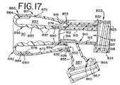
本発明の乳房シールドの第14実施形態が図17に示され、そしてこれは前の図16の実施形態と似ている。外シールド部はベース部822及びカップ形片875を有するツーピース剛性構造体である。搾乳器(図示せず)との取り外し可能な連結用のねじを含む一体取付けのポンプカラー824がある。ベース部822の前方端は、外側壁832、内側壁828及び相互連結用ベース壁826を含む一体形成のU形リング830を有し、これらの壁は一緒になってU形チャンネルを構成する。外側壁832は、以下に説明する方法で、カップ片875の取り付け用のねじ付内面831を有する。
A fourteenth embodiment of the breastshield of the present invention is shown in FIG. 17 and is similar to the previous embodiment of FIG. The outer shield part is a two-piece rigid structure having a
ベース部822にはポート852が形成され、このポートは少なくとも1カ所853でU形チャンネルのベース壁826に通じる出口を有する。正圧又は負圧流体源が圧力ポート852に連結され、そして後で説明するように、U形リング又はチャンネル830に流体が運ばれる。
The
剛性外シールド部のベース部はまた下方に傾斜した管状部材855を有する。管状部材855は、短い延長部865で終わる底端を有する。延長部865には、米国特許第4,929,229号に示されているような弁組立体が取り付けられる。勿論、このような弁組立体はここに説明する他の実施形態にも用いられる。瓶(図示せず)との取付けようの雌ねじ867を含む取付けカラー866がある。管状部材の内部を857で示す。
The base portion of the rigid outer shield also has a
カップ片875は側壁872で形成される。その後方端はU形リングの壁832のねじ付内面に螺合するための雄ねじ部分874を含む。カップ片875の前方端、剛性リング形繋ぎ部材884の内面から突出したビード880を受け入れるための、側壁872の内面に形成された溝878を有する。剛性繋ぎ部材884は、外シールド部のカップ片のタイプと同じか均等であるタイプのプラスチック材料で作られるのが好ましく、そして可撓性内シールド部886に恒久的に取り付けられる。
可撓性内シールド部886は、繋ぎ部材884から前方湾曲部分892へ延び、それから内側壁898へ延びる単一壁部材で構成される。第2剛性リング形繋ぎ部材890が側壁898の後方(下流)端に取り付けられる。剛性繋ぎ部材890はベース部のU形チャンネル内に受け入れられて滑り係合で側壁828の内面に接触する。剛性繋ぎ部材890はベース部のU形チャンネル内のカップ片側壁872から間隔を隔てていて、出口853と連通した空間を残している。その空間はカップ片側壁872と可撓性内シールド部886との間に構成されたキャビティ又はチャンバー833に通じている。可撓性内シールド部886の側壁898は再度、女性の乳房及び乳頭を受け入れる内部空間90を構成する。
The flexible
乳房シールド817は可撓性ダイヤフラム910を更に含む。ダイヤフラムは前端912と円筒体を形成する側壁構造体913とを有し、円筒体はこの前端912が閉鎖されている。この円筒体には僅かに凹んだ部分があり、これはベース部の管状部分855の頂(上流)端へ導く領域の上に位置する。これは、まもなく明らかになるように、乳を管状部分855へ流入させるのに役立つ。ダイヤフラムの後方端はフランジ状延長部917を含み、これはダイヤフラムをカラー824の前方端に着座させるのに役立つ。ダイヤフラムの内部空間を919で示す。
図17のこの実施形態の作動に転じる前に、可撓性内シールド部886が内側に面した波形面を有していることがわかる。これは、内部90に沿って山と谷構造体を形成する厚い円周領域897で形成されている。
Before turning to the operation of this embodiment of FIG. 17, it can be seen that the flexible
作動中、正圧及び又は負圧流体源がポート852に(図示しないが、容易に理解される連結部を介して)連結される。負圧(吸引)が通常の方法でポンプカラー824につながれる。ダイヤフラムの内部919に付与された負圧は間欠的であり、ダイヤフラム910の周期的な収縮及び膨張を引き起し、内部空間90内に真空が作られ、この真空は内部空間内の乳房及び乳頭に作用する。かくして、ダイヤフラムはカラー824に付与される真空源を乳供給から隔絶するのに役立つ。このタイプのダイヤフラム及びその作動の更なる詳細は米国特許第5,941,847号から収集することができる。乳は凹み部分914の下を流れて管状部分855に流入し、それ故に収集瓶に至る。
In operation, positive and / or negative pressure fluid sources are coupled to port 852 (not shown, but easily understood). Negative pressure (suction) is coupled to the
圧力ポート852に伝えられた正圧及び又は負圧により、チャンバー833の体積を膨張又は収縮させる。これにより、可撓性内シールド部側壁898を内部空間90内の乳房及び乳頭に対して内方に又は外方に移動させる。撓み作用は出っ張り897を乳房及び乳頭に押しつけ、それによって乳房を門でちちの搾り出しを容易にする。
The positive and / or negative pressure transmitted to the
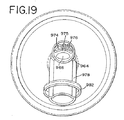
本発明に従って作られた第15実施形態950を図18、19、及び20に示す。この実施形態の乳房シールド950は、じょうご部分952、円筒部分956、及び管状部材978で構成された単一片の剛性外シールド部を有する。じょうご部分の周囲はフランジ又はリム954で構成されている。円筒部分956と管状部材は両方とも、以下で詳細に説明するように、一体に形成されたバレル部分962と連通する。傾斜管状部材978は、周知のように、取付けカラー(図示せず)で乳収集瓶を取り付けるための取付けリング982を含む底端980を有する。傾斜管状部材978は、管状部材978内に真空通路986を構成する分離壁又はスプラッシュ壁984を更に含み、管状部材の内部を全体的に988で示す。
A
バレル部分962はポンプとの取付け用のポンプカラー964を含み、ポンプは電動搾乳器にするつもりではあるが、手動(手動往復ピストンタイプ)ポンプでもよい。ポンプカラー964は2つの通路又はポートを構成し、そのうちの1つはポート968であり、もう1つはポート966である。ポート966は出口990を介して真空通路986と連通する。ポート/通路968の前方端は出口972で終わっている。
The
図19を参照すると、ポート968は実際には、バレル部分962内に形成された3つの圧力ポート/通路974、975、976を含むことが分かるであろう。これらのポート/通路の特徴はすぐに明らかになろう。
Referring to FIG. 19, it can be seen that the
可撓性内シールド部993はまたこの実施形態の乳房シールド950を形成し、この実施形態では、可撓性内シールド部は剛性外シールド部内に摩擦的に挿入される。可撓性内シールド部993は可撓性円錐部材992及び管状延長部996で構成され、これら円錐部材と管状延長部は一緒になって内部空間90を構成する。円錐部材992の前方端は管状リム998によって構成された周縁を有し、管状リム998は下方に延びたリップ999を有する。リム998はフランジ954に受け入れられて可撓性内シールド部を乳房シールドの前に固定し且つ位置決めする。図18で分かるように、管状延長部996は側壁957、958の内面に当接するように寸法決めされた後方端で終わり、側壁957、958はこの領域で剛性外シールド部を構成する。この摩擦係合はこの領域で管状延長部996を固定し且つ位置決めするのに十分である。
The flexible
図19A、21、22で最も良く分かるように、内シールド部はまた管状延長部に一体に形成された分配マニホルド部材100を含む。分配マニホルド部材100は、第1環状チャンネル1008、第2環状チャンネル1010及び第3環状チャンネル1012と連通する第1チャンネル1002、第2チャンネル1004及び第3チャンネル1006を含む。各チャンネル1008、1010、1012は内シールド部の残部よりも薄い肉厚を有する(図18参照)。チャンネル1008、1010、1012の肉厚及び形状はこの実施形態の作動で説明される機能面を有する。図18で最も良く分かるように、例えば、第1環状チャンネル1008及び第2環状チャンネル1010は互いに長手方向に間隔を隔てており、そして管状延長部996に沿って配置され、第3管状チャンネルは1012は円錐部材992内部空間に形成される。
As best seen in FIGS. 19A, 21, and 22, the inner shield also includes a
各環状チャンネルは、内シールド部構成部品と外シールド部構成部品が組み合わされるとき、それぞれの環状空気チャンバー1014、1016、1018を形成する。図18で最もよく分かるように、内シールド部が外シールド部に挿入されるとき、分配マニホルド部材100がそれぞれの第1通路1006、第2通路1004、第3通路1002を経て圧力ポート974、975、976に連結される。
Each annular channel forms a respective
作動中、負圧流体源(図示せず)はポンプカラー964に連結され、負圧が内チャンバー966に伝えられ、内チャンバー966は真空を出口990を介して、遂には内部空間90へ伝える。負圧及び又は正圧流体源もポート968につながれる。これは3つのチャンバー1014、1016、1018に同時に作動する単一の源であっても良く、或いは複数の圧力源がそれぞれのポート974、975、976に連結される。この開示全体を通して、この様な複数の圧力源を、圧力を分割し、並びに独立に制御して、単一の真空/正圧源から得てもよいことが理解されよう。真空が第1圧力ポート974、第2圧力ポート975、第3圧力ポート976を通して与えられると仮定すると、真空は分配マニホルド1000のそれぞれの第1通路1002、第2通路1004、第3通路1006を通して伝えられ(図19A参照)、分配マニホルドはチャンバー1014、1016、1018内に真空を引く。
In operation, a negative pressure fluid source (not shown) is connected to the
真空は薄肉の環状チャンネルを点線で示す位置に、即ち外側に引く。従って、付与される間欠的な真空(真空の解放で)はチャンバー1014、1016、1018を構成する側壁の周期的な撓みを引き起こす。内部空間90内に受け入れられた女性の乳房は第3環状空気チャンバー1018の撓み作用によって揉まれ、乳頭は第1環状空気チャンバー1014及び第2環状空気チャンバー1016の撓みによって揉まれる。各チャンバーへの圧力の独立の制御で、チャンバーの作動順序、並びにこれらのチャンバーの側壁が、該側壁によって乳房及び乳頭に及ぼされる正圧の制御により乳房又は乳頭を動かしている触覚感覚の量について色々なパターンを得ることが出来る。
The vacuum draws a thin annular channel in the position indicated by the dotted line, i.e. outward. Thus, the intermittent vacuum applied (by releasing the vacuum) causes periodic deflection of the sidewalls that make up the
図20には本発明の乳房シールドの第16実施形態が図示されている。この実施形態は図18、19、19A、21及び22の前に提示した実施形態と大変似ており、従って、剛性外シールド部の説明は行わない、と言うのは、実施形態が今説明した実施形態と構造的に同じであるからである(同じ数字は再度同じ部分をさす)。しかしながら、前の内シールド部と本内シールド部との間にはある構造状の違いがある。 FIG. 20 shows a sixteenth embodiment of the breast shield of the present invention. This embodiment is very similar to the embodiment presented before FIGS. 18, 19, 19A, 21 and 22, and therefore no description of the rigid outer shield is given, since the embodiment has just described. This is because it is structurally the same as the embodiment (the same numbers refer to the same parts again). However, there is a structural difference between the previous inner shield part and the main inner shield part.
この実施形態1020では、内シールド部は、前の実施形態の幾分球根状の内方に延びた環状チャンネルの代わりに、第1環状空気ダクト1022、第2環状空気ダクト1024、第3環状空気ダクト1026を備えている。各空気ダクトは、前に説明した環状チャンネル1008、1010、1012とほぼ同じ相対位置で内シールド部を形成する側壁内に長方形横断面の環状キャビティを設けることによって形成される。しかしながら、実際の横断面キャビティは大変顕著ではない。ダクトは可撓性内シールド部の側壁1028をダクトにわたって薄くするように形成され、かくして、ダクト領域に、図20に示す位置に1032で指示した通常の厚さよりも薄い横断面肉厚を残す。各空気ダクトの位置は前の実施形態に設けられた環状チャンネル1008、1010、1012の位置に相当する。
In this
図20の実施形態は、正圧流体源がダクト1022、1024、1026に付与されるようになっていることを除けば、前に説明した実施形態と同じ方法で機能する。この結果、ダクトにわたって側壁を内方に(内部空間90の中へ)膨らませ、図20に点線で示すように環状の出っ張りを作る。再度、タイミング及び量が更に修正され、且つ制御される正圧流体の間欠的な供給は内部空間90に向かったり遠ざかったりする円筒撓みを生じさせ、それによって揉み効果を行わせる。
The embodiment of FIG. 20 functions in the same manner as the previously described embodiment, except that a source of positive pressure fluid is applied to the
図23に注目すると、本発明の乳房シールドの第17実施形態1035図23に示すように、剛性外シールド部は円筒部分1045に一体に接合された前円錐部分1036を含み、1042で指示した内側壁面を有する。円錐部分1036の前端は平滑なリップ又はリム1041で終わっている。
Turning to FIG. 23, a
図23のこの実施形態における可撓性内側壁(一方の側だけを横断面で示す)は、一緒になって内部空間90を構成する円錐部分1055及び管状部分1056で構成される。円錐部分1055は女性の乳房を受け入れ、管状部分1056は乳頭を受け入れる。円錐部分1055の前端は幾分厚いビード状周囲1060で終わっていることが分かる。この周囲ビードは剛性円錐部分1036のリム1041に当たる。管状部分1056の他端即ち下流端は円筒部分1045内に緩く受け入れられる。
The flexible inner wall (only one side is shown in cross section) in this embodiment of FIG. 23 is comprised of a
出口1066が可撓性内シールド部の円錐部分55を構成する壁に形成され、そして周囲ビード1060と半径方向内側に形成され且つそれと同心のもう1つの円周ビード1068との間に構成されたチャンネル1067へ延びる。図で分かるように、可撓性内シールド部が剛性外シールド部内に挿入されるとき、両者の間に、リム1041とビード1060との界面の所を除いて、可撓性内シールド部の実質的に全長に沿って空間1070が形成されている。
An
乳頭に接触するようにした円周出っ張り1072が管状部分1056の内側壁に沿って形成される。
A
作動として、内部空間90と空間1070の両方が真空下にあるように、負圧流体源(図示せず)が前に説明し、或いは同様に知られた手段によりもうけるべきであることは予想される。内部空間90内部空間に受け入れられた女性の乳房は吸引を受ける。負圧も空間1070に及び、チャンネル1067で乳房のまわりにシールを作る。乳房に及ぼす吸引と関連して空間1070内部空間に与えられる負圧により、可撓性内シールド部の管状部分1056を真空源に向かって、即ち使用者の乳房から軸線方向に遠ざかる方向に吸引させる。図面はこれを点線で示し、管状延長部の端1073は図示したように移動する。内シールド部の管状部分1056の内面に設けられた突出部又は出っ張り1072も同じ伸び位置まで移動し、「チャイニーズフィンガーグリップ効果」として特徴付けられているもの出ある点で、乳頭を引く。
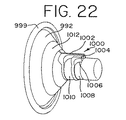
In operation, it is anticipated that a negative pressure fluid source (not shown) should be provided by means previously described or similarly known such that both
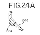
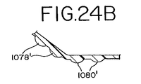
図25、24B、24Cに移ると、図25には、図23の形態の変形例が示されている。一連の無秩序に位置した中実の又は変形例として気泡タイプの突出部が可撓性内シールド部の円錐部分1055及び管状部分1056全体に設けられる。この実施形態では、突出部は卵形を有し、各突出部の物理的な大きさは変えてもよいので、第1列の大きい卵形突出部1078は同じ半径平面に沿って設けられる。大きい卵形突出部1078の位置間には中間の大きさの卵形突出部1080が配置され、その各々もそれぞれの同じ半径平面に沿って設けられる。同様に、突出部は徐々に小さくなっていて、円錐部分1055から管状部分1056まで順次延びる一連の半径平面に沿って設けられる。先に述べたように、可撓性内シールド部と剛性外シールド部との間の空間1070には負圧が与えられ、それにより、内シールド部を長手方向に伸長させる。かくして、突出部の形状、配列、位置に応じて、また突出部が中実であるか気泡形態であるかに応じて、内部空間内に配置される乳房及び乳頭が僅かに異なる揉み効果を受けるであろう。これらの突出部の他の実施形態への適応は理解されよう。
Turning to FIGS. 25, 24B, and 24C, FIG. 25 shows a modification of the form of FIG. A series of randomly positioned solid or modified bubble-type protrusions are provided throughout the
図24Cは気泡タイプ構造を示す。図24Bは1078‘および1080’で指示した中実の突出部を利用する。 FIG. 24C shows a bubble type structure. FIG. 24B utilizes solid protrusions indicated by 1078 'and 1080'.
図26にはこの同じ形態についての他の変形例が示されており、この変形例では、リング突出部が採用される。これらのリング突出部は円錐部分にリング1084、中間リング1086を含み、中間リング1086の下流にリング1088があり、このリングは管状部分1056の前方端で始まる。リング1084、1086、1088は中実突出部でもよいし、空気チャンバーとして設けられても良く、若しくはその両方の組み合わせでもよい。真空源が内シールド部と外シールド部との間の空間1070に適用されるとき、内シールド部は再度女性の乳房から長手方向に遠ざかるので、リング(中実に突出するかチャンバーをなすか)は内部空間90内部空間に受け入れられた乳房及び乳頭の同時揉みを引き起こす。リング1084に近い円錐部分の横断面図を図24Aに示す。
FIG. 26 shows another modified example of the same form, and in this modified example, a ring protrusion is employed. These ring protrusions include a
図26の実施形態の更に他の変形例を図27に示す。この例では、一連の間欠的な又は不連続なリングが設けられる。これらのリングはまた雄セグメント及び雌セグメントとして交互に設けられ、即ち一方のセグメントは内側に延び、他方のセグメントは外側に凹まされる。雄セグメント1090は突出部を呈し、雌セグメント1091は乳房に対して凹みを呈している。セグメントは、セグメント1092、1093で示すように、徐々に小さくなるのがよい。
FIG. 27 shows still another modification of the embodiment of FIG. In this example, a series of intermittent or discontinuous rings are provided. These rings are also provided alternately as male and female segments, ie one segment extends inward and the other segment is recessed outward. The
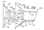
図28には本乳房シールド1095の第18実施形態が示されている。この実施形態では、剛性外シールド部は、前方リム又はリップ1100をもった円錐部材1096を有し、剛性外シールド部の下流端の詳細は省かれている、何故ならば任意の数の上記実施形態が同じものを供給するからである。図28のこの実施形態によって与えられる違いは外シールド部の一方の側に設けられた圧力マニホルド1110であり、これは第1入口ポート1112、第2入口ポート1114、第3入口ポート1116を含む。入口ポートの機能はまもなくより詳細に説明される。
FIG. 28 shows an eighteenth embodiment of the
図28の乳房シールド1095はまた可撓性内シールド部1094を含み、この内シールド部は、この実施形態では、厚い円周及び阿賀手方向リブ状構造体のスケルトンフレームで形成されている。可撓性内シールド部1094は管状延長部1126へ一体に延びる円錐部分1120で構成されている。各部分1120、1126は形状が剛性外シールド部の円錐部分1096及び円筒部分1103にほぼ補足し合う。
The
スケルトンフレームは一般的には、外シールド部の内側壁と係合するように形成され、且つ一連の長手方向に間隔を隔てた円周又は周囲リブ1152、1154、1156、1158、及び長手方向に延びた補剛リブ1160、1164、1166で構成されている。
The skeleton frame is generally formed to engage the inner wall of the outer shield and is a series of longitudinally spaced circumferential or
可撓性内側壁1094が外シールド部内に挿入されるとき、可撓性内シールド部1094のリム1133はリム1100に係合して内シールド部をこの接合部で固定する。間隔を隔てた円周リブ1152、1154、1156、1158は、剛性外シールド部の管状部分1103を構成する、側壁の内壁面に気密シールを形成する。リブ間に存在する空間は複数の別々の圧力チャンバー1169、1171、1173を形成する。各圧力チャンバー1169、1171、1173はそれぞれ、圧力マニホルド1110の第1入口ポート1112、第2入口ポート1114、第3入口ポート1116と連通している。かくして、圧力マニホルド1110に与えられる正圧流体源(図示せず)は、各圧力チャンバー1169、1171、1173と対応する可撓性内シールド部を、例えば、図20のドーナツ状と同じドーナツ状をなして内部空間90の中へ膨張させる。負圧流体源(図示せず)が周知の方法で内部空間90に与えられるので、内部空間90に受け入れられた乳房に作用する吸引と膨張した形体で乳房及び乳頭に付与された正圧との組み合わせが乳房と乳頭を同時に揉んで乳の搾り出しを容易にする。変形例として、また、圧力マニホルドを介して真空を引くことができ、それによって、この方法で真空源を乳房から隔絶する。長手方向の補剛リブ1160、1164、1166は高さが円周リブよりも半径方向に低いことが気づかれるであろう。補剛リブは可撓性内シールド部がその長手方向長さにそって接触又は拡張する傾向を減ずるのに役立つ。
When the flexible
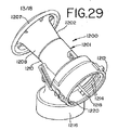
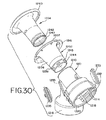
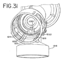
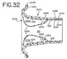
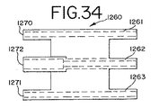
他の実施形態を図29乃至34(及び34A及び34B)に示す。この実施形態1200は、ベース部であるもの1201と乳房受け部であるもの1202との2つの主ピースで構成された剛性外シールド部を有する。可撓性内シールド部を1204で指示する。前方円錐部分1207及び僅かにテーパした管状部分1208が乳房受け部1202を作り上げる。この乳房受け部1202はベース部1201の補足し合う形状の管状部分1210でベース部1201とスナップ係合する。スナップ係合をこのあとで説明する。受け部の管状部分1208の下流端のマウントを形成するベース部の管状部分1210はカラー1212の中へ延び、手動ポンプが、例えばネジ山1214によりネジ山付係合部を介してカラー1212に取り付けられる。電動式ポンプをカラー1212にチューブを介して連結してもよく、この係合部を以下で更に説明する。ベース部1201はまた通常の仕方で瓶との連結のためのカラー1216を有する。
Another embodiment is shown in FIGS. 29-34 (and 34A and 34B). This
ベース部1201はカラー1212に形成された第1横ポート1218及び第2ポート1220を有する。図31で分かるように、例えば、これらのポート1218、1220とカラー1212の開放端から前後方向に延びるトラフ又はチャンネルとして始まり、以下で説明するように、ベース部の更なる構造体内に延びるそれぞれの貫通穴1222、1221で終わる。
The
ポート1218、1220に加えて、ポート1230(図31)がある。ポート1230は乳房受け部の内部空間90(図32)の中へ延び、そして内部空間90内の乳房及び乳頭に主たる負圧(吸引)を与える。ポート1218、1220はそれらのそれぞれの貫通穴1221、1222を経て、ベース部1201に形成されたそれぞれの通路又は導管の中へ延び、この通路又は導管はポート/貫通穴1220/1221用に1233で指示され、示されてはいないが、同様の導管が他の側にポート/貫通穴1218/1222用に設けられている。この特定な実施形態にしよされる成形法の結果、キャップ1235がこれらの導管の外側を閉じる。導管1233は、管状部分1210を構成する側壁の内部出口(図示せず)で終わっている。
In addition to
上記の内部出口は、乳房受け部1202が管状部分1210に取り付けられるとき、乳房受け部1202の管状部分の後方端に形成された穴1238と整合する。その取付けは、可撓性内シールド部1204を乳房受け部1202内に挿入して可撓性内シールド部1204を乳房受け部1202内に置くことによって行われ、可撓性内シールド部の前方端のビード状リム1241が乳房受け部の前方端のフランジ又はリム1241にスナップ嵌めする。可撓性内シールド部の後方部分は溝1242及び末端ビード1243を有し、溝及びビードは、可撓性内シールド部が折り返されるとき(図30及び32参照)、乳房受け部1202の下流端のビード1244及び溝1245にそれぞれ受け入れられる。これはまた可撓性内シールド部を剛性乳房受け部1202及びベース部1201の相互連結部におけるガスケットとして使用するのに役立つ。
The internal outlet is aligned with a
図32に示すように、可撓性内シールド部1204は内側壁1250と外側壁1251を有する二重壁構造体で作られている。外側壁1251には、剛性外シールド部1202の側壁に形成された穴1238と連通する1つ又はそれ以上の穴1254が設けられている。この二重壁構造体は可撓性内シールド部1204のチャンバー1255を作る。側壁1251は変形例として除去されてもよい。
As shown in FIG. 32, the flexible
図34、34A、34Bを参照すると、圧力源をこの実施形態の乳房シールドに連結する際に使用される連結具1260が示されている。連結具は側方通路1261、1263と中央通路1262とを有する構造体からなる。ポート/貫通穴1218/1222、1220/1221及びポート1230内に受け入れられるべく寸法決めされ且つ12701271及び1272でそれぞれ指示された前方連結体がある。反対側の端にはチューブで適当な圧力源との連結のためのニップルが形成されている。
Referring to FIGS. 34, 34A, 34B, there is shown a connector 1260 used in connecting a pressure source to the breast shield of this embodiment. The connector consists of a structure having
連結具1260をカラー1212内に置くと、圧力源を内部空間90及びチャンバー1255に色々に連結することが出来る。例えば、負圧源を連結具1260の上記のチューブ連結部の各々に連結することができる。この結果、乳房は内部空間90の中へ吸引によって引き込まれる。同時に、例えば、チャンバー1255の体積を減じ、それによって側壁1250を半径方向外方に吸引する。
When the connector 1260 is placed in the
水、ゲル、空気、等で満たされた後、チャンバー1255を恒久的にシールする目的で、製造の際に使用するこめの一体成形のプラグ1270が設けられる。正圧が内チャンバー1255に付与されたら、有利には、剛性スナップリングがリム1240及び1241にかぶせて使用される。
After filling with water, gel, air, etc., an integrally formed
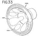
図33は前の実施形態の乳房受け部1202の変形態様を示す。この乳房受け部1280は、あらゆる意図と目的のために、乳房に与えられる1つの対象の内側壁1250の代わりに、複数の内側に開放した凹面1281、1282を有する点をのぞいて乳房受け部1202のものと同じである。可撓性内シールド部に外側に付与された負圧により可撓性内シールド部をこれらの凹面に引き入れることができる。
FIG. 33 shows a modification of the
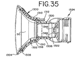
図35及び36は本発明の更に他の実施形態を示す。この乳房シールドは剛性外シールド部1300及び可撓性内シールド部1302を有する。2つのシールド部1300及び1302は一体のユニットとして成形される。可撓性内シールド部1302は円周リム1304から僅かに内で始まり、そして外シールド部1300の管状延長部1306へ延び、延長部の壁へ比較的平滑に移行する。
35 and 36 show still another embodiment of the present invention. The breast shield has a rigid
外シールド部1300の内部にはリング1308が形成され、可撓性内シールド部1302はこの領域で外シールド部に位置する。外シールド部の横側には、剛性シールドに強さを加えることができ或いはある審美性を単に果たす追加のストラット状構造体1310が形成されている。圧力源からのホースの連結用の差し込み1312が外シールド部1302に形成され、そして剛性外シールド部の内部と連通する。
A
可撓性内シールド部1302の外側と外シールド部1300の内部との間に空間1318が設けられる。
A
管状延長部1306はこれと同心に形成された管状カラー1320を有する。その同心構成は後方開口から閉鎖前方端に向かってテーパした薄いリング形の隙間を作る。この隙間の中にベース部1324の補足し合う形状の管状部分1322が受け入れられる。管状部分は干渉嵌めで受け入れられ、そして組合わさった内シールド部及び外シールド部をベース部に取り付けるのに役立つ。外シールド部1300から下方に垂下したエプロン1330はベース部分1324の連結部分1326の湾曲に合う湾曲を有し、そして向きを正しくし、取付けを安定化させるのに役立つ。後壁1334は管状部分1322の後方側に有る。
ポート1336が真空を圧力源からついには可撓性内シールド部1302の内部に伝える。真空はポート1336から、出口1340を経て連結部分1326に通じた内チャンネル1338に通る。その連結部分1326は、真空がスプラッシュガード1344を通り越し入口1346を介してベース部1324の管状部分1322の中へ通り続けるように、フラップ弁構造体(図示せず)によって閉じられる。管状カラー1320へ絞り出された乳は同じ入口1346(今は出口として機能し、この関係では入口/出口は相対的な用語である)を通って、連結部分1326に流入し、遂には乳容器に入る。
Port 1336 conducts vacuum from the pressure source and finally to the interior of flexible
差し込み1312を通して正圧又は負圧を付与することができる。1つの例では、乳頭/乳房を引く内部真空の作用で可撓性内シールド部1302が内側に移動するのを初期に防止するように、可撓性内シールド部1302内に構成された内部空間90への間欠的な負圧(真空)と同時に負圧を内部空間1318に付与してもよい。次いで、その外部真空(即ち空間内)を解放することができ、次いで、搾り出し順序の有利な段階で、正圧を付与して可撓性内シールド部1302を乳房に押しつけて乳房を優しく絞る。しかし、これは異なる圧力を空間1318及び内部空間90に付与する1つの方法である。
Positive or negative pressure can be applied through the
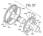
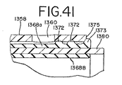
第21実施形態が図37乃至41に図示されている。この実施形態は図33について論じたものと同様な内シールド部及び外シールド部と、図35及び36に関して説明したものとどうようなベース部とを有する。特に、剛性外シールド部1350は、僅かにテーパした管状部分1358へ延びる前方円錐部分1357を有する。前に説明した凹面1281が外シールド部の長手方向軸線の周りに対象的に設けられる(その軸線は本質的にはこの実施形態では対象軸線である)。ポート1360が管状部分1358の側壁を貫いて延び、ポート1238(即ち図32)について説明したような方法で機能する。
A twenty-first embodiment is illustrated in FIGS. This embodiment has an inner shield portion and an outer shield portion similar to those discussed with respect to FIG. 33, and what is described with respect to FIGS. 35 and 36. In particular, the rigid
外シールド部の円周リム1362は、垂直平面において間隔を隔てた2つの外側に延びたフランジ1362a及び1362bで構成される。これらのフランジはまもなく説明される方法で可撓性内シールド部1366に係合する。
The
シリコーン等で作られた可撓性内シールド部1366は、じょうご形外シールド部1350の形状と一致する形状を有する単壁構造体で構成されている。内シールド部は円錐部分1370に合体する管状延長部分1368を有する。内シールド部1366の管状延長部分1368はその後方(下流)端に、一連の外側に延びる円周出っ張り1372、1373を有し、これら出っ張りは、内シールド部と外シールド部が合わされるとき管状部分1358の内側壁と係合する(図41参照)。出っ張り1373は管状部分1358の後方縁1375に位置し、そして内シールド部をこの端で適所に位置決めするのに役立つ。剛性管状(リング形)スリーブ又はカラー1380が管状延長部1368のツーピース領域の内側に嵌まり、このツーピース領域は側壁1368aと1368bで構成される。スリーブ1380は補剛要素であり、管状部分1368が使用中適所にしっかりととどまるようにする。
The flexible
円錐部分1370は外シールド部のリム1362にスナップ嵌めする円周リム1382を有する。内側に延びる円周ビード1382aがリム要素1362aと1362bとの間の隙間に受け入れられる。リム1382にはドーナツ形チャンネル1384が形成され、このチャンネルリング1386を受け入れる。リング1386は外シールド部と内シールド部のこの前方(上流)端での係合を確実にする補剛要素である。
The
内シールド部はその最前方端に僅かに内に向いたリップ1390を有していることに気づくであろう。これは、乳房シールドが乳房から外れて傾いたとき、乳が乳房シールドからこぼれるのを防止するのに役立つ。
It will be noted that the inner shield has a slightly inwardly facing
可撓性内シールド部1366はその両側に形成された突出部1392を更に有する。これらの突出部1392は内部空間90の中へ内方に曲がる(それにより、外側に凹む)。突出部は主として円錐部分1370にあるが、管状延長部1368へも延びる。外シールド部と組みたてられるとき、突出部は一組の凹面1281に位置するのが好ましい。
The flexible
使用中、内シールド部と外シールド部との間の内空間に(ポート1360から)付与された正圧は突出部並びにスリーブ1380より上の可撓性内シールド部を乳房/乳頭に押しつけるのに役立つ。負圧(真空)は突出部並びに内シールド部を、もしも必要なだけ十分であれば、凹面1281へ引く。これは、乳の搾り出しを高め、吸っているとき子供の口、唇及び舌を暗示する母の「感触」をもたらす。
During use, the positive pressure applied to the inner space between the inner and outer shields (from port 1360) pushes the protrusion and the flexible inner shield above the
かくして、多数の実施形態を種々説明したけれども、当業者は、異なる実施形態が、他の実施形態に使用し得る他の潜在的な特徴/設計を示すことを認識するであろう。より多くの変更、適用及び修正も発明の精神及び範囲に依然として入るであろう。 Thus, although a number of embodiments have been described in various ways, those skilled in the art will recognize that different embodiments show other potential features / designs that may be used in other embodiments. More changes, applications and modifications will still fall within the spirit and scope of the invention.
Claims (21)
ベース部に取り付けられた乳房受け部、前記乳房受け部は、可撓性内側壁をもった膨張可能なチャンバーを有し、前記可撓性内側壁は乳頭を含む女性の乳房の少なくとも一部分を受け入れるようになった内部空間を構成し、前記乳房受け部は、平滑に湾曲した前方壁へ延び、次いで円周内側壁へ延びる円周外側壁を作る可撓性材料の単一片で形成され、前記側壁は互いに間隔を隔てて膨張チャンバーを形成し、前記前方壁は円周内側壁によって形成された、前記内部への開口を構成し、前記側壁はベース部に取り付けられた後方端壁構造体で終わっており、前記後方端壁構造体は前記側壁を隔てることによって形成された開放リング形チャンネルであり、前記ベース部材は、前記リング形チャンネルに受け入れられるリング形カラーを有し、前記乳房受け部は前記リング形カラーに密封可能に取り付けられ、前記ベース部及び前記乳房受け部の一方に形成され、第1流体圧力源との連結のために前記内部空間と連通している第1ポート、
前記ベース部及び前記乳房受け部の一方に形成され、第2流体圧力源との連通のために前記膨張可能なチャンバーと連通している第2ポート、
を含む、搾乳器用乳房シールド。 A base member having a port through which air and milk pass,
A breast receptacle attached to a base, said breast receptacle having an inflatable chamber with a flexible inner wall, said flexible inner wall receiving at least a portion of a female breast including a teat The breast receptacle is formed of a single piece of flexible material that extends to a smoothly curved front wall and then to a circumferential outer wall that extends to a circumferential inner wall, Side walls form an expansion chamber spaced apart from each other, the front wall is an inner opening formed by a circumferential inner wall, and the side wall is a rear end wall structure attached to a base portion. And the rear end wall structure is an open ring-shaped channel formed by separating the sidewalls, and the base member has a ring-shaped collar that is received in the ring-shaped channel; A breast receiving portion is sealably attached to the ring-shaped collar, is formed on one of the base portion and the breast receiving portion, and communicates with the internal space for connection with a first fluid pressure source. 1 port,
A second port formed in one of the base portion and the breast receptacle portion and in communication with the inflatable chamber for communication with a second fluid pressure source;
Including breast shield for breast pump.
前記外シールド部内に取り付けられた内シールド部、該内シールド部は乳房シールドに内側壁を形成し、乳頭を含む女性の乳房の少なくともいくらかを受け入れかつ乳房と実質的に気密接触してそれを取り囲むようになった内部を構成する。
前記内シールド部に形成された可撓性領域、該可撓性領域は乳房シールド内に受け入れられた乳房に対して移動でき、
前記可撓性領域と前記外シールド部との間に構成された第1空間、
流体圧力源を前記第1空間に連結するため、前記第1空間と連通する第1ポート、前記第1空間への正の流体圧力源の付与により、前記空間を膨張させ、それによって前記可撓性領域を移動させ、
前記内部と連通する第2ポート、それによって、前記内部への負圧源の付与により、乳房を内部へ更に引き入れさせる、
乳房シールド。 Rigid outer shield part made of left and right parts joined together,
An inner shield portion mounted within the outer shield portion, the inner shield portion forming an inner wall in the breast shield that receives and surrounds at least some of the female breast, including the nipple, in substantial airtight contact with the breast Configure the interior now.
A flexible region formed in the inner shield portion, the flexible region being movable relative to a breast received in the breast shield;
A first space configured between the flexible region and the outer shield part;
In order to connect a fluid pressure source to the first space, a first port communicating with the first space, the application of a positive fluid pressure source to the first space, expands the space, thereby the flexible space Move the sex area,
A second port in communication with the interior, thereby further pulling the breast into the interior by applying a negative pressure source to the interior;
Breast shield.
Applications Claiming Priority (2)
| Application Number | Priority Date | Filing Date | Title |
|---|---|---|---|
| US09/888,322 US6663587B2 (en) | 2001-06-22 | 2001-06-22 | Breastshield with multi-pressure and expansible chamber construction, related breastpump and method |
| US09/888,322 | 2001-06-22 |
Related Parent Applications (1)
| Application Number | Title | Priority Date | Filing Date |
|---|---|---|---|
| JP2008286983A Division JP2009028557A (en) | 2001-06-22 | 2008-11-07 | Breast shield with multi-pressure and expansible chamber construction, related breast pump and method |
Publications (1)
| Publication Number | Publication Date |
|---|---|
| JP2012254307A true JP2012254307A (en) | 2012-12-27 |
Family
ID=25392973
Family Applications (3)
| Application Number | Title | Priority Date | Filing Date |
|---|---|---|---|
| JP2003506954A Ceased JP2005502397A (en) | 2001-06-22 | 2002-06-21 | Breast shield with multi-pressure and inflatable chamber structure, associated breast pump and method |
| JP2008286983A Ceased JP2009028557A (en) | 2001-06-22 | 2008-11-07 | Breast shield with multi-pressure and expansible chamber construction, related breast pump and method |
| JP2012166242A Pending JP2012254307A (en) | 2001-06-22 | 2012-07-26 | Breastshield with multi-pressure and expansible chamber construction, related breastpump and method |
Family Applications Before (2)
| Application Number | Title | Priority Date | Filing Date |
|---|---|---|---|
| JP2003506954A Ceased JP2005502397A (en) | 2001-06-22 | 2002-06-21 | Breast shield with multi-pressure and inflatable chamber structure, associated breast pump and method |
| JP2008286983A Ceased JP2009028557A (en) | 2001-06-22 | 2008-11-07 | Breast shield with multi-pressure and expansible chamber construction, related breast pump and method |
Country Status (8)
| Country | Link |
|---|---|
| US (4) | US6663587B2 (en) |
| EP (4) | EP2316501A1 (en) |
| JP (3) | JP2005502397A (en) |
| AT (1) | ATE522238T1 (en) |
| AU (1) | AU2002322292C1 (en) |
| CA (1) | CA2451967A1 (en) |
| NZ (1) | NZ530347A (en) |
| WO (1) | WO2003000313A1 (en) |
Cited By (1)
| Publication number | Priority date | Publication date | Assignee | Title |
|---|---|---|---|---|
| JP2016514516A (en) * | 2013-03-24 | 2016-05-23 | ナヤ ヘルス, インコーポレイテッド | Methods, apparatus, and systems for expression and quantification of human breast milk |
Families Citing this family (134)
| Publication number | Priority date | Publication date | Assignee | Title |
|---|---|---|---|---|
| SE9904723D0 (en) * | 1999-12-22 | 1999-12-22 | Carlsson A Research Ab | New modulators of dopamine neurotransmission II |
| US7014759B2 (en) * | 2000-02-18 | 2006-03-21 | Radford Thomas K | Method and apparatus for water purification |
| JP2002336347A (en) * | 2001-05-18 | 2002-11-26 | Univ Nihon | Breast pump |
| US6866994B2 (en) * | 2001-05-30 | 2005-03-15 | Neomatrix, Llc | Noninvasive intraductal fluid diagnostic screen |
| NO315309B1 (en) * | 2001-06-18 | 2003-08-18 | Mamma Lactans As | Breast cup, and method of making breast cup, and method of pumping breast milk by means of breast cup |
| DE10297607T5 (en) | 2001-12-27 | 2005-01-27 | Playtex Products, Inc., Westport | Breast pump system |
| US20050197640A1 (en) * | 2002-02-28 | 2005-09-08 | Say Samuel L. | Portable battery operated aspirator |
| US6749582B2 (en) * | 2002-04-30 | 2004-06-15 | The First Years Inc. | Pumping breast milk |
| WO2004026368A2 (en) * | 2002-09-17 | 2004-04-01 | Puronyx, Inc | Breast pump with massage features |
| US20040127845A1 (en) * | 2002-12-27 | 2004-07-01 | Playtex Products, Inc. | Breast pump system |
| US7776008B2 (en) * | 2003-08-08 | 2010-08-17 | Playtex Products, Inc. | Manual breast pump |
| US8137305B2 (en) * | 2007-01-22 | 2012-03-20 | Kelly Patricia A | Programmable electric breast pump |
| US7381197B2 (en) * | 2003-08-20 | 2008-06-03 | Kelly Patricia A | Electric breast pump |
| US8052635B1 (en) | 2003-08-20 | 2011-11-08 | Kelly Patricia A | Electrical breast pump and flexible breast cup system |
| CN1697664A (en) * | 2003-10-30 | 2005-11-16 | 贝亲株式会社 | Breast pump |
| US20050154348A1 (en) * | 2004-01-08 | 2005-07-14 | Daniel Lantz | Breast pump |
| KR101138743B1 (en) * | 2004-01-27 | 2012-04-24 | 메델라 홀딩 아게 | Breast cap system and breast cap insert for the same |
| DE102004004057B4 (en) * | 2004-01-27 | 2008-07-10 | Maier Jun., Jakob | liner |
| WO2005084729A1 (en) * | 2004-03-04 | 2005-09-15 | Medela Holding Ag | Breast cup insert |
| JP3907057B2 (en) * | 2004-03-30 | 2007-04-18 | ピジョン株式会社 | Milking machine |
| US8152754B2 (en) * | 2004-04-01 | 2012-04-10 | Medela Holding Ag | Soft breastshield |
| US7396339B2 (en) | 2004-04-30 | 2008-07-08 | The First Years Inc. | Pumping breast milk |
| US7354418B2 (en) * | 2004-05-06 | 2008-04-08 | L. Jason Clute | Express kits and cup liners for human milking apparatus |
| WO2005118022A1 (en) * | 2004-06-03 | 2005-12-15 | Medela Holding Ag | Disposable breast shield set |
| US7569031B2 (en) * | 2004-06-22 | 2009-08-04 | The First Years Inc. | Breast pump |
| US20060111665A1 (en) * | 2004-11-19 | 2006-05-25 | Gillan Jonathan C | Reclining breast pumping system |
| US7819839B2 (en) * | 2004-11-19 | 2010-10-26 | Gillan Jonathan C | Reclining breast pumping system |
| NO20050494D0 (en) * | 2005-01-28 | 2005-01-28 | Aasmund Torvik | Breast pump for pumping milk. |
| EP1866008B1 (en) * | 2005-04-07 | 2014-04-16 | Medela Holding AG | Valve, especially for a breast cup set, and breast cup set with valve |
| US20070060873A1 (en) * | 2005-09-15 | 2007-03-15 | Katsuyuki Hiraoka | Milking apparatus |
| DE102006019830A1 (en) * | 2005-11-24 | 2007-06-06 | Westfaliasurge Gmbh | Teat rubber for use on a teat cup |
| US20070135761A1 (en) * | 2005-12-09 | 2007-06-14 | Cheng Kai-Sheng | Breast pump |
| US7806855B2 (en) | 2006-04-11 | 2010-10-05 | Playtex Products, Inc. | Manual breast pump |
| US9162016B2 (en) * | 2006-09-22 | 2015-10-20 | Medela Holding Ag | Breastpump with irregular milk expression sequences |
| US8187227B2 (en) | 2006-11-01 | 2012-05-29 | Medela Holding Ag | Self returning contamination barrier |
| KR100826938B1 (en) * | 2007-01-10 | 2008-05-02 | 이한덕 | Breast pump for massaging breast |
| JP4505757B2 (en) * | 2007-04-02 | 2010-07-21 | ジェクス株式会社 | Milking machine |
| JP4505756B2 (en) * | 2007-04-02 | 2010-07-21 | ジェクス株式会社 | Milking machine |
| US8070716B2 (en) * | 2007-04-11 | 2011-12-06 | Medela Holding Ag | Method and apparatus for minimum negative pressure control, particularly for a breastpump with breastshield pressure control system |
| US8070715B2 (en) * | 2007-04-11 | 2011-12-06 | Medela Holding Ag | Method and apparatus for minimum negative pressure control, particularly for breastpump with breastshield pressure control system |
| CN201064581Y (en) * | 2007-07-04 | 2008-05-28 | 程克勇 | Manual breast pump |
| DE112008001755T5 (en) * | 2007-07-24 | 2010-06-02 | Medela Holding Ag | Apparatus for the treatment of breast conditions |
| US8945046B2 (en) | 2008-04-03 | 2015-02-03 | Lyndon Brittner | Hands-free breast pump system |
| AU2009231652B2 (en) * | 2008-04-03 | 2015-03-19 | Lyndon Brittner | Hands-free breast pump system |
| JP5204533B2 (en) * | 2008-04-04 | 2013-06-05 | ピジョン株式会社 | Milking machine |
| EP2172236A1 (en) * | 2008-10-03 | 2010-04-07 | Koninklijke Philips Electronics N.V. | Breast pump system |
| EP2349378A4 (en) * | 2008-11-07 | 2013-12-18 | Simplisse Inc | Breast pump |
| ITPR20080088A1 (en) * | 2008-12-23 | 2010-06-24 | Medel S P A | MILK COLLECTION KIT FOR AN EQUIPMENT TO TAKE MILK FROM A BREAST |
| CN101474433A (en) * | 2009-01-06 | 2009-07-08 | 张连盛 | Bionic sucking device of breast pump |
| WO2010083485A2 (en) | 2009-01-16 | 2010-07-22 | Learning Curve Brands, Inc. | Breast pump and method of use |
| EP2233163A1 (en) * | 2009-03-26 | 2010-09-29 | Koninklijke Philips Electronics N.V. | An insert for a breast pump |
| EP2263710A1 (en) * | 2009-06-18 | 2010-12-22 | Koninklijke Philips Electronics N.V. | An insert for a breast pump |
| WO2011005286A1 (en) * | 2009-06-22 | 2011-01-13 | Lansinoh Laboratories, Inc. | Breast milk collection apparatus and components thereof |
| GB0912229D0 (en) * | 2009-07-14 | 2009-08-26 | Jackel Int Ltd | A breast pump |
| JP6047402B2 (en) * | 2009-09-22 | 2016-12-21 | メデラ ホールディング アーゲー | Apparatus and method for milking human breast milk |
| US8529501B2 (en) | 2010-06-04 | 2013-09-10 | Medela Holding Ag | One time use breastpump assembly |
| ES2536053T3 (en) | 2010-07-23 | 2015-05-20 | Avacen, Inc. | Apparatus for the therapeutic application of thermal energy |
| EP2412391A1 (en) | 2010-07-27 | 2012-02-01 | Koninklijke Philips Electronics N.V. | A breast pump |
| EP2502639A1 (en) * | 2011-03-21 | 2012-09-26 | Koninklijke Philips Electronics N.V. | A breast pump |
| JP5726622B2 (en) * | 2011-04-28 | 2015-06-03 | ピジョン株式会社 | Milking machine |
| EP2604300A1 (en) * | 2011-12-12 | 2013-06-19 | Koninklijke Philips Electronics N.V. | Breast shield for a breast pump |
| CN102657902A (en) * | 2012-04-25 | 2012-09-12 | 陈进水 | Milk collecting device for simulating infant milk sucking way |
| EP2687246A1 (en) * | 2012-07-20 | 2014-01-22 | Acute Ideas Co., Ltd. | Milk expressing device capable of simulating a baby's suckling |
| US8961454B2 (en) * | 2012-07-24 | 2015-02-24 | Chean-Shui Chen | Milk expressing device capable of simulating a baby's suckling |
| CN104661694B (en) | 2012-09-24 | 2016-12-14 | 皇家飞利浦有限公司 | Breast pump |
| CH707124A1 (en) | 2012-10-25 | 2014-04-30 | Medela Holding Ag | Breastshield unit with media separator. |
| CH707363A1 (en) * | 2012-12-18 | 2014-06-30 | Medela Holding Ag | Breastshield unit with media separation. |
| CH707364A1 (en) * | 2012-12-18 | 2014-06-30 | Medela Holding Ag | Breastshield unit. |
| CN105025950B (en) * | 2013-03-05 | 2018-01-19 | 皇家飞利浦有限公司 | Breast interface is easily assembled for breast pump |
| EP2964286B1 (en) * | 2013-03-05 | 2018-07-18 | Koninklijke Philips N.V. | Liner and breast interface for a breast pump |
| US9192509B2 (en) * | 2013-03-11 | 2015-11-24 | Avacen, Inc. | Methods and apparatus for therapeutic application of thermal energy including blood viscosity adjustment |
| US9687385B2 (en) | 2013-03-11 | 2017-06-27 | Avacen, Inc. | Methods and apparatus for therapeutic application of thermal energy including blood viscosity adjustment |
| US20150065994A1 (en) * | 2013-08-29 | 2015-03-05 | Positive Care Ltd. | Posterior breast massage unit |
| US10080825B2 (en) * | 2013-09-05 | 2018-09-25 | Lansinoh Laboratories, Inc. | Connector for collection and dispensing of breast milk or colostrum |
| US10426705B2 (en) * | 2013-09-05 | 2019-10-01 | Lansinoh Laboratories, Inc. | Colostrum collection system |
| WO2015035224A1 (en) * | 2013-09-05 | 2015-03-12 | Maternal Life, Llc | Connector for collection and dispensing of breast milk or colostrum |
| US10485908B2 (en) | 2014-02-06 | 2019-11-26 | Exploramed Nc7, Inc. | Apparatus and methods to create posterior compression at the breast during expression of breast milk |
| US10639406B2 (en) | 2014-03-20 | 2020-05-05 | Exploramed Nc7, Inc. | Methods and apparatus for transferring pressure during expression of human breast milk |
| US10617805B2 (en) | 2014-03-20 | 2020-04-14 | Exploramed Nc7, Inc. | Fluid measuring reservoir for breast pumps |
| US9623160B2 (en) | 2014-09-19 | 2017-04-18 | Naya Health, Inc. | Quantification and inventory management of expressed human breast milk |
| CN106687155A (en) | 2014-07-07 | 2017-05-17 | 纳亚健康公司 | Methods and apparatus for transferring pressure during expression of human breast milk |
| WO2016007560A1 (en) * | 2014-07-07 | 2016-01-14 | Naya Health, Inc. | Pump apparatus and methods for expression of human breast milk |
| US11660380B2 (en) | 2014-07-22 | 2023-05-30 | Willow Innovations, Inc. | Breast pump system with collection container |
| CN112691246A (en) | 2014-07-22 | 2021-04-23 | 威洛创新股份有限公司 | Breast pump system and method |
| CN115814184A (en) | 2014-07-22 | 2023-03-21 | 威洛创新股份有限公司 | Breast pump system and method |
| WO2016014483A1 (en) | 2014-07-22 | 2016-01-28 | Exploramed Nc7, Llc | Breast pump system and methods |
| WO2016014488A1 (en) | 2014-07-22 | 2016-01-28 | Exploramed Nc7, Llc | Breast pump system and methods |
| CN110639073B (en) | 2014-08-11 | 2022-05-17 | 威洛创新股份有限公司 | Synchronization of breast pumping with infant feeding |
| WO2016033107A1 (en) * | 2014-08-26 | 2016-03-03 | Mimeo Labs, Inc. | Breast fluid expression device |
| KR20170066435A (en) | 2014-09-16 | 2017-06-14 | 익스플로라메드 엔씨7, 인크. | Systems, devices and methods for assessing milk volume expressed from a breast |
| CN104587543B (en) * | 2015-02-02 | 2019-01-01 | 新文越婴童用品(上海)有限公司 | A kind of automatic massage breast pump cup |
| USD785160S1 (en) | 2015-02-20 | 2017-04-25 | Medela Holding Ag | Membrane for a breastshield of a breast pump |
| CN104784766B (en) * | 2015-05-05 | 2018-04-17 | 陈俊波 | A kind of threeway part and the breast pump with this threeway part |
| US11717599B2 (en) * | 2015-05-07 | 2023-08-08 | Babyation Inc. | Breast shield for a breast pump system |
| CA2989318C (en) * | 2015-08-14 | 2023-09-26 | Medela Holding Ag | Mflp-valve for a pressure source |
| AU2016311498B2 (en) * | 2015-08-27 | 2020-10-08 | Medela Holding Ag | Lacteal extractor safety system and method for pump system |
| WO2017083769A1 (en) * | 2015-11-13 | 2017-05-18 | Naya Health, Inc. | Apparatus and methods to create posterior compression at the breast during expression of breast milk |
| AU2017217702B2 (en) | 2016-02-10 | 2022-02-03 | Willow Innovations, Inc. | Breast pump container assemblies and methods |
| CN113648473A (en) | 2016-02-10 | 2021-11-16 | 威洛创新股份有限公司 | Breastpump assembly and method |
| US10434231B2 (en) * | 2016-04-29 | 2019-10-08 | Exploramed Nc7, Inc. | Apparatus and methods for biomimetic expression of breast milk |
| CN106075620A (en) * | 2016-07-07 | 2016-11-09 | 东莞亲亲我实业有限公司 | Breast pad, cover body and breast pump |
| CN109641088A (en) * | 2016-09-02 | 2019-04-16 | 美德乐控股公司 | Humalacter |
| US10702640B2 (en) * | 2016-12-02 | 2020-07-07 | Exploramed Nc7, Inc. | Systems and methods for expression of breast milk |
| US10016548B1 (en) * | 2017-01-11 | 2018-07-10 | Carr Lane Quackenbush | Breast pump |
| US12005166B2 (en) * | 2017-01-11 | 2024-06-11 | Momtech Inc. | Breast pump |
| US11147905B2 (en) * | 2017-01-11 | 2021-10-19 | Momi Brands, Inc. | Breast pump |
| US11116880B2 (en) | 2019-10-29 | 2021-09-14 | Momi Brands, Inc. | Manual breast pump |
| US11413381B2 (en) * | 2017-01-11 | 2022-08-16 | Momtech Inc. | Breast pump |
| WO2018144948A1 (en) | 2017-02-03 | 2018-08-09 | Avacen Medical, Inc. | Systems and methods for evaluating blood circulation and early detection of cardiovascular issues |
| ES2951176T3 (en) | 2017-06-15 | 2023-10-18 | Chiaro Technology Ltd | Breast pump system |
| DE102017119034A1 (en) * | 2017-08-21 | 2019-02-21 | Elisabeth Kurth | Baby Mouth Simulator |
| RU178263U1 (en) * | 2017-12-07 | 2018-03-28 | Илья Александрович Куратов | Apparatus for hydro-vacuum electroporation skin treatment |
| US11298445B2 (en) * | 2018-01-09 | 2022-04-12 | Moxxly, LLC | Breast pump milk flow rate sensor system and apparatus |
| EP3539583A1 (en) | 2018-03-12 | 2019-09-18 | Koninklijke Philips N.V. | Breast shield arrangement for a breast pump |
| CN108671290A (en) * | 2018-06-06 | 2018-10-19 | 江苏医药职业学院 | A kind of promoting lactation inhales newborn holder |
| JP2022500209A (en) | 2018-09-06 | 2022-01-04 | ランシノー ラボラトリーズ,インコーポレイティド | Vibration waveform for milking machine |
| WO2020051456A1 (en) | 2018-09-06 | 2020-03-12 | Lansinoh Laboratories, Inc. | Breast pumps |
| WO2020051438A1 (en) | 2018-09-06 | 2020-03-12 | Lansinoh Laboratories, Inc. | Closed loop electric breast pump |
| WO2020069072A1 (en) * | 2018-09-26 | 2020-04-02 | Ameda, Inc. | High cycle vacuum breast pump |
| US20220362443A9 (en) * | 2019-02-06 | 2022-11-17 | Amanda Quarles | Hands-free milk extraction and collection device |
| CN114650801A (en) * | 2019-07-29 | 2022-06-21 | 巴比娅什公司 | Breast pump system |
| CN110279905A (en) | 2019-08-02 | 2019-09-27 | 中山纽迈适贸易有限公司 | Inhale clawpiece |
| KR102339586B1 (en) * | 2019-09-27 | 2021-12-17 | 주식회사 해님 | Breast pump apparatus and breast shield therefor |
| US11931491B2 (en) * | 2020-02-19 | 2024-03-19 | Marcella Lee Post | Breast pump flange assembly and method of use |
| AU2021222419A1 (en) * | 2020-02-21 | 2022-08-25 | Medela Holding Ag | Breast shield |
| GB202004395D0 (en) | 2020-03-26 | 2020-05-13 | Chiaro Technology Ltd | Lima |
| CN111588927A (en) * | 2020-05-21 | 2020-08-28 | 方国峰 | Milk bowl and breast pump for breast pump |
| CA3201257A1 (en) * | 2020-12-07 | 2022-06-16 | Jenny TENG | Breast pump systems and methods |
| EP4059532A1 (en) * | 2021-03-16 | 2022-09-21 | Koninklijke Philips N.V. | Diaphragm for a breast pump and a breast pump having the diaphragm |
| CN215386356U (en) * | 2021-07-29 | 2022-01-04 | 浙江科宝母婴用品有限公司 | Tee bend structure and breast pump |
| TW202327668A (en) * | 2022-01-04 | 2023-07-16 | 研能科技股份有限公司 | Breast pump |
| TWI797945B (en) * | 2022-01-04 | 2023-04-01 | 研能科技股份有限公司 | Breast pump |
| WO2023244481A1 (en) * | 2022-06-13 | 2023-12-21 | Nooshee Inc. | Breast milk distribution system and uses thereof |
| GB2622571A (en) * | 2022-08-31 | 2024-03-27 | Chiaro Technology Ltd | A breast shield for a breast pump |
Citations (4)
| Publication number | Priority date | Publication date | Assignee | Title |
|---|---|---|---|---|
| DE431808C (en) * | 1925-02-10 | 1926-07-16 | Heinrich Grupe Jun | Milking machine, the teat cup of which receives a number of air cushions lying one below the other to be pushed over the teat, which are inflated and deflated one after the other |
| US1786786A (en) * | 1927-05-14 | 1930-12-30 | Babson Mfg Corp | Teat cup |
| JPS421898Y1 (en) * | 1963-12-31 | 1967-02-04 | ||
| JP2001511025A (en) * | 1996-11-12 | 2001-08-07 | マンマ・ラクタンス・エイエス | Breast pump for human breast |
Family Cites Families (37)
| Publication number | Priority date | Publication date | Assignee | Title |
|---|---|---|---|---|
| US956325A (en) | 1909-05-25 | 1910-04-26 | Joseph B Fey | Massage cup or tip. |
| US1032518A (en) | 1911-05-27 | 1912-07-16 | Emma Pauline Thieringer | Nipple-shield. |
| US1721739A (en) | 1928-02-17 | 1929-07-23 | Daniel J Kennedy | Breast protector |
| GB533493A (en) | 1939-11-13 | 1941-02-13 | Mildred Brown | Improvements in and relating to breast (mammary) pumps |
| NL73732C (en) * | 1948-10-08 | |||
| BE524638A (en) | 1952-12-04 | |||
| US3822703A (en) | 1973-02-13 | 1974-07-09 | P Davisson | Breast pump |
| DE2451953A1 (en) | 1974-10-31 | 1976-05-06 | Bernhard Moser | Milking machine teat cup - consists of cup sleeve containing teat rubber with pumped pulsating space between |
| FR2380784A1 (en) | 1977-02-22 | 1978-09-15 | Adams Frank | Suction pump for human milk - has hollow cup and squeeze bulb for peristaltic action, combined with suction bottle |
| US4249481A (en) * | 1977-02-22 | 1981-02-10 | Adams Frank H | Milking apparatus and method |
| US4263912A (en) | 1977-06-08 | 1981-04-28 | Adams Frank H | Milking apparatus and method |
| US4323067A (en) | 1977-06-20 | 1982-04-06 | Adams Frank H | Combination breast pump and gavage feeding apparatus and method |
| US4857051A (en) | 1980-09-05 | 1989-08-15 | Isg/Ag | Breastpump |
| CH659949A5 (en) | 1983-05-20 | 1987-03-13 | Larsson K O A H | Suction cup for a device for extracting breast milk |
| US4607596A (en) * | 1983-05-11 | 1986-08-26 | Whittlestone Walter G | Milking methods and apparatus |
| US4680028A (en) | 1984-07-02 | 1987-07-14 | Lact-Assist, Incorporated | Flexible breast receptor for breast pump |
| CH666614A5 (en) | 1984-12-24 | 1988-08-15 | Isg Ag | METHOD OF PROMOTING LABOR IN PREGNANT WOMEN. |
| US4772262A (en) | 1985-04-16 | 1988-09-20 | Natural Technologies, Inc. | Portable electric breast pump |
| ATE64310T1 (en) * | 1986-02-28 | 1991-06-15 | Ameda Ag | INSERT FOR BREAST PUMP. |
| US4740196A (en) * | 1986-07-24 | 1988-04-26 | Powell Margaret D | Nursing apparatus |
| US4929229A (en) | 1988-11-30 | 1990-05-29 | Isg/Ag | Breastpump having improved valve mechanism |
| CH676795A5 (en) * | 1989-03-01 | 1991-03-15 | Ameda Ag | |
| US5049126A (en) | 1990-02-16 | 1991-09-17 | Isg/Ag | Breast pump with nipple stimulating insert |
| SU1745262A1 (en) | 1990-05-05 | 1992-07-07 | Донецкий медицинский институт им.М.Горького | Device for breast milk aspiration |
| CA2046525A1 (en) * | 1990-07-10 | 1992-01-11 | Karl O. A. H. Larsson | Breast pump with massage for improved lactation |
| US5100406A (en) | 1990-11-01 | 1992-03-31 | Graham-Field, Inc. | Silicone breast pump insert |
| DE4102634A1 (en) | 1991-01-30 | 1992-08-06 | Erika Knapp | Device to stimulate flow of milk from mammary gland - consists of rubber sleeve which fits over breast, and includes air supply |
| GB9502995D0 (en) * | 1995-02-16 | 1995-04-05 | Cannon Rubber Ltd | Breast pump insert |
| US5941847A (en) | 1998-02-06 | 1999-08-24 | Medela Holding Ag | Breast shield with vacuum isolation element |
| US6277052B1 (en) * | 1998-05-28 | 2001-08-21 | Kenneth W. Howard | Method and system for passively exercising selected portions of a human body |
| CA2240268A1 (en) * | 1998-06-10 | 1999-12-10 | Deborah M. Mackenzie | Breast pump assembly |
| GB2340755B (en) | 1998-08-24 | 2002-09-25 | Cannon Rubber Ltd | Breast pump insert |
| JP2001009024A (en) * | 1999-06-30 | 2001-01-16 | Kooshin Kk | Breast pump |
| JP2001058005A (en) * | 1999-08-23 | 2001-03-06 | Pigeon Corp | Milker |
| NZ512318A (en) * | 2000-06-12 | 2003-01-31 | Lorne Jason Clute | Breast pump |
| US6866994B2 (en) * | 2001-05-30 | 2005-03-15 | Neomatrix, Llc | Noninvasive intraductal fluid diagnostic screen |
| NO315309B1 (en) * | 2001-06-18 | 2003-08-18 | Mamma Lactans As | Breast cup, and method of making breast cup, and method of pumping breast milk by means of breast cup |
-
2001
- 2001-06-22 US US09/888,322 patent/US6663587B2/en not_active Expired - Lifetime
-
2002
- 2002-06-21 NZ NZ530347A patent/NZ530347A/en unknown
- 2002-06-21 JP JP2003506954A patent/JP2005502397A/en not_active Ceased
- 2002-06-21 EP EP10181205A patent/EP2316501A1/en not_active Withdrawn
- 2002-06-21 WO PCT/US2002/019781 patent/WO2003000313A1/en active IP Right Grant
- 2002-06-21 AU AU2002322292A patent/AU2002322292C1/en not_active Ceased
- 2002-06-21 EP EP02756271A patent/EP1404394B1/en not_active Expired - Lifetime
- 2002-06-21 AT AT02756271T patent/ATE522238T1/en not_active IP Right Cessation
- 2002-06-21 EP EP10010459A patent/EP2298369B1/en not_active Expired - Lifetime
- 2002-06-21 EP EP10183271A patent/EP2308523A1/en not_active Withdrawn
- 2002-06-21 CA CA002451967A patent/CA2451967A1/en not_active Abandoned
-
2003
- 2003-07-15 US US10/619,834 patent/US7166087B2/en not_active Expired - Lifetime
-
2006
- 2006-12-14 US US11/639,350 patent/US7662127B2/en not_active Expired - Lifetime
-
2008
- 2008-11-07 JP JP2008286983A patent/JP2009028557A/en not_active Ceased
-
2010
- 2010-01-14 US US12/687,331 patent/US7988661B2/en not_active Expired - Fee Related
-
2012
- 2012-07-26 JP JP2012166242A patent/JP2012254307A/en active Pending
Patent Citations (4)
| Publication number | Priority date | Publication date | Assignee | Title |
|---|---|---|---|---|
| DE431808C (en) * | 1925-02-10 | 1926-07-16 | Heinrich Grupe Jun | Milking machine, the teat cup of which receives a number of air cushions lying one below the other to be pushed over the teat, which are inflated and deflated one after the other |
| US1786786A (en) * | 1927-05-14 | 1930-12-30 | Babson Mfg Corp | Teat cup |
| JPS421898Y1 (en) * | 1963-12-31 | 1967-02-04 | ||
| JP2001511025A (en) * | 1996-11-12 | 2001-08-07 | マンマ・ラクタンス・エイエス | Breast pump for human breast |
Cited By (1)
| Publication number | Priority date | Publication date | Assignee | Title |
|---|---|---|---|---|
| JP2016514516A (en) * | 2013-03-24 | 2016-05-23 | ナヤ ヘルス, インコーポレイテッド | Methods, apparatus, and systems for expression and quantification of human breast milk |
Also Published As
| Publication number | Publication date |
|---|---|
| NZ530347A (en) | 2005-11-25 |
| US20070088250A1 (en) | 2007-04-19 |
| US20020198489A1 (en) | 2002-12-26 |
| JP2005502397A (en) | 2005-01-27 |
| US7166087B2 (en) | 2007-01-23 |
| EP2298369A1 (en) | 2011-03-23 |
| EP2316501A1 (en) | 2011-05-04 |
| AU2002322292C1 (en) | 2009-01-08 |
| ATE522238T1 (en) | 2011-09-15 |
| AU2002322292B2 (en) | 2008-07-17 |
| US20040015127A1 (en) | 2004-01-22 |
| EP2308523A1 (en) | 2011-04-13 |
| EP1404394A4 (en) | 2008-03-26 |
| EP1404394B1 (en) | 2011-08-31 |
| EP2298369B1 (en) | 2013-02-20 |
| US7988661B2 (en) | 2011-08-02 |
| CA2451967A1 (en) | 2003-01-03 |
| JP2009028557A (en) | 2009-02-12 |
| WO2003000313A1 (en) | 2003-01-03 |
| EP1404394A1 (en) | 2004-04-07 |
| US6663587B2 (en) | 2003-12-16 |
| US20100121267A1 (en) | 2010-05-13 |
| US7662127B2 (en) | 2010-02-16 |
Similar Documents
| Publication | Publication Date | Title |
|---|---|---|
| JP2012254307A (en) | Breastshield with multi-pressure and expansible chamber construction, related breastpump and method | |
| AU2002322292A1 (en) | Breastshield with Multi-pressure and Expansible Chamber Construction, Related Breastpump and Method | |
| EP0727234B1 (en) | Breast pump insert | |
| TWI583408B (en) | Breastshield unit | |
| JP5156702B2 (en) | Breast wrap for milking pump assembly | |
| USRE47111E1 (en) | Soft breastshield | |
| US9248223B2 (en) | Insert for a breast pump | |
| US5049126A (en) | Breast pump with nipple stimulating insert | |
| US20180064859A1 (en) | Highly efficient breastpump and system for expressing breastmilk | |
| US5941847A (en) | Breast shield with vacuum isolation element | |
| RU2612503C2 (en) | Breast pump | |
| IL141606A (en) | Breast pump insert | |
| TW201811381A (en) | Breast shield | |
| EP0198651A2 (en) | An apparatus for applying a vacuum to a part of a human or animal body | |
| MXPA06011409A (en) | Soft breastshield |
Legal Events
| Date | Code | Title | Description |
|---|---|---|---|
| A131 | Notification of reasons for refusal |
Free format text: JAPANESE INTERMEDIATE CODE: A131 Effective date: 20130917 |
|
| A02 | Decision of refusal |
Free format text: JAPANESE INTERMEDIATE CODE: A02 Effective date: 20140303 |