JP2012253921A - Motor, robot hand and robot - Google Patents
Motor, robot hand and robot Download PDFInfo
- Publication number
- JP2012253921A JP2012253921A JP2011125103A JP2011125103A JP2012253921A JP 2012253921 A JP2012253921 A JP 2012253921A JP 2011125103 A JP2011125103 A JP 2011125103A JP 2011125103 A JP2011125103 A JP 2011125103A JP 2012253921 A JP2012253921 A JP 2012253921A
- Authority
- JP
- Japan
- Prior art keywords
- actuator
- biasing
- driven
- motor
- urging
- Prior art date
- Legal status (The legal status is an assumption and is not a legal conclusion. Google has not performed a legal analysis and makes no representation as to the accuracy of the status listed.)
- Withdrawn
Links
- 238000006243 chemical reaction Methods 0.000 abstract description 11
- 230000003014 reinforcing effect Effects 0.000 description 10
- 239000000463 material Substances 0.000 description 6
- 238000010586 diagram Methods 0.000 description 4
- 229910052451 lead zirconate titanate Inorganic materials 0.000 description 3
- PXHVJJICTQNCMI-UHFFFAOYSA-N Nickel Chemical compound [Ni] PXHVJJICTQNCMI-UHFFFAOYSA-N 0.000 description 2
- 238000005452 bending Methods 0.000 description 2
- 229910052751 metal Inorganic materials 0.000 description 2
- 239000002184 metal Substances 0.000 description 2
- 239000005060 rubber Substances 0.000 description 2
- 229910001220 stainless steel Inorganic materials 0.000 description 2
- 239000010935 stainless steel Substances 0.000 description 2
- 229910013641 LiNbO 3 Inorganic materials 0.000 description 1
- 238000000151 deposition Methods 0.000 description 1
- 238000006073 displacement reaction Methods 0.000 description 1
- 229910052737 gold Inorganic materials 0.000 description 1
- 238000007689 inspection Methods 0.000 description 1
- HFGPZNIAWCZYJU-UHFFFAOYSA-N lead zirconate titanate Chemical compound [O-2].[O-2].[O-2].[O-2].[O-2].[Ti+4].[Zr+4].[Pb+2] HFGPZNIAWCZYJU-UHFFFAOYSA-N 0.000 description 1
- GQYHUHYESMUTHG-UHFFFAOYSA-N lithium niobate Chemical compound [Li+].[O-][Nb](=O)=O GQYHUHYESMUTHG-UHFFFAOYSA-N 0.000 description 1
- 238000000034 method Methods 0.000 description 1
- 229910052759 nickel Inorganic materials 0.000 description 1
- 230000003287 optical effect Effects 0.000 description 1
- 239000010453 quartz Substances 0.000 description 1
- VYPSYNLAJGMNEJ-UHFFFAOYSA-N silicon dioxide Inorganic materials O=[Si]=O VYPSYNLAJGMNEJ-UHFFFAOYSA-N 0.000 description 1
- 238000004544 sputter deposition Methods 0.000 description 1
- 238000007740 vapor deposition Methods 0.000 description 1
- 229910052726 zirconium Inorganic materials 0.000 description 1
Images


Classifications
-
- B—PERFORMING OPERATIONS; TRANSPORTING
- B25—HAND TOOLS; PORTABLE POWER-DRIVEN TOOLS; MANIPULATORS
- B25J—MANIPULATORS; CHAMBERS PROVIDED WITH MANIPULATION DEVICES
- B25J9/00—Programme-controlled manipulators
- B25J9/10—Programme-controlled manipulators characterised by positioning means for manipulator elements
- B25J9/12—Programme-controlled manipulators characterised by positioning means for manipulator elements electric
-
- B—PERFORMING OPERATIONS; TRANSPORTING
- B25—HAND TOOLS; PORTABLE POWER-DRIVEN TOOLS; MANIPULATORS
- B25J—MANIPULATORS; CHAMBERS PROVIDED WITH MANIPULATION DEVICES
- B25J15/00—Gripping heads and other end effectors
- B25J15/0009—Gripping heads and other end effectors comprising multi-articulated fingers, e.g. resembling a human hand
-
- H—ELECTRICITY
- H02—GENERATION; CONVERSION OR DISTRIBUTION OF ELECTRIC POWER
- H02N—ELECTRIC MACHINES NOT OTHERWISE PROVIDED FOR
- H02N2/00—Electric machines in general using piezoelectric effect, electrostriction or magnetostriction
- H02N2/0005—Electric machines in general using piezoelectric effect, electrostriction or magnetostriction producing non-specific motion; Details common to machines covered by H02N2/02 - H02N2/16
- H02N2/001—Driving devices, e.g. vibrators
- H02N2/003—Driving devices, e.g. vibrators using longitudinal or radial modes combined with bending modes
- H02N2/004—Rectangular vibrators
-
- H—ELECTRICITY
- H02—GENERATION; CONVERSION OR DISTRIBUTION OF ELECTRIC POWER
- H02N—ELECTRIC MACHINES NOT OTHERWISE PROVIDED FOR
- H02N2/00—Electric machines in general using piezoelectric effect, electrostriction or magnetostriction
- H02N2/10—Electric machines in general using piezoelectric effect, electrostriction or magnetostriction producing rotary motion, e.g. rotary motors
- H02N2/103—Electric machines in general using piezoelectric effect, electrostriction or magnetostriction producing rotary motion, e.g. rotary motors by pressing one or more vibrators against the rotor
Abstract
Description
本発明は、モーター、ロボットハンドおよびロボットに関する。 The present invention relates to a motor, a robot hand, and a robot.
圧電素子の振動によって被駆動体を駆動するモーターとしては、矩形平板状の圧電素子が、一体的に形成された突起を有する補強板に積層されたアクチュエーターを、補強板の突起を被駆動体に当接させて被駆動体を駆動するモーターが知られている(特許文献1)。この圧電アクチュエーターを備えるモーターでは、被駆動体に圧電アクチュエーターの補強板に有する突起を当接させるための付勢手段を備え、付勢手段により発生する付勢力による補強板の突起と被駆動手段との間の摩擦力が、補強板の略楕円の軌跡を描く突起の振動を被駆動手段へ伝え、被駆動手段を所定の方向へと駆動させるものであった。 As a motor for driving a driven body by vibration of a piezoelectric element, a rectangular plate-shaped piezoelectric element is an actuator laminated on a reinforcing plate having a protrusion formed integrally, and a protrusion on the reinforcing plate is used as a driven body. A motor that drives a driven body by abutting is known (Patent Document 1). The motor provided with the piezoelectric actuator includes a biasing means for bringing the driven body into contact with a protrusion provided on the reinforcing plate of the piezoelectric actuator, and the protrusion of the reinforcing plate by the biasing force generated by the biasing means and the driven means. The frictional force between them transmits the vibrations of the protrusions that draw a substantially elliptical locus of the reinforcing plate to the driven means, and drives the driven means in a predetermined direction.
上述の特許文献1では、付勢手段は補強板の突起を被駆動手段の回転中心に向かって付勢するように、補強板を含む圧電アクチュエーターの両脇にばね部材を配置している。しかし、補強板の突起は略楕円の軌跡で動作するために、付勢力に対する被駆動体からの補強板の突起への反力は、被駆動手段の回転中心に向かう付勢力の方向に対して交差する方向に発生する。この付勢力の方向に交差する反力によって補強板の突起の動作が所望の楕円軌跡を描かなくなる、すなわちアクチュエーターの振動を被駆動手段の駆動力に変化する効率を低下させる要因となってしまう課題があった。
In the above-mentioned
そこで、被駆動手段からのアクチュエーターへの反力が、アクチュエーターの振動を、被駆動手段の駆動力へ変換させることの障害とならない付勢手段によって、効率の良いモーターと、そのモーターを用いたロボットハンドおよびロボットを提供する。 Therefore, an efficient motor and a robot using the motor by a biasing means in which the reaction force from the driven means to the actuator does not become an obstacle to converting the vibration of the actuator into the driving force of the driven means Provide hands and robots.
本発明は、少なくとも上述の課題の一つを解決するように、下記の形態または適用例として実現され得る。 The present invention can be realized as the following forms or application examples so as to solve at least one of the above-described problems.
〔適用例1〕本適用例のモーターは、円柱状の回転面を有する被駆動手段と、前記被駆動手段の前記回転面に付勢する突起を端部に有する振動板と、前記振動板に積層される圧電体と、を有するアクチュエーターと、前記アクチュエーターを前記被駆動手段に付勢する付勢手段と、を備えるモーターであって、前記被駆動手段を駆動させる前記アクチュエーターの振動によって描かれる前記突起の楕円軌跡を、前記回転面と接するように配置し、前記楕円軌跡と前記回転面との接点を接点P、前記アクチュエーターに前記付勢手段による付勢力が作用する作用点を作用点Q、前記被駆動手段の回転中心を回転中心R、とした場合、前記付勢手段の付勢方向と、前記回転中心Rと前記接点Pとを結ぶ方向と、でなす角度θ1と、前記付勢手段の付勢方向と、前記接点Pと前記作用点Qを結ぶ方向と、でなす角度θ2と、は、
θ1<θ2
であることを特徴とする。
[Application Example 1] A motor according to this application example includes a driven unit having a cylindrical rotating surface, a diaphragm having a projection biased to the rotating surface of the driven unit at an end, and a vibrating plate A motor comprising: an actuator having a laminated piezoelectric body; and an urging means for urging the actuator to the driven means, wherein the motor is depicted by vibration of the actuator that drives the driven means An elliptical trajectory of the protrusion is arranged so as to be in contact with the rotation surface, a contact point between the elliptical trajectory and the rotation surface is a contact P, and an action point where an urging force by the urging means acts on the actuator is an action point Q, When the rotation center of the driven means is the rotation center R, the angle θ1 formed by the urging direction of the urging means and the direction connecting the rotation center R and the contact P, and the urging means of And energizing direction, the direction connecting the acting point Q and the contact P, a angle θ2 forming in, the
θ1 <θ2
It is characterized by being.
上述の適用例によれば、θ1,θ2を上述の関係にすることにより、振動板の突起を被駆動手段の回転中心に向かわせないとする被駆動手段から振動板の突起に作用する反力の分力を抑制し、アクチュエーターに励起させる振動を高い効率で被駆動手段の回転力に変換することができる。 According to the application example described above, the reaction force acting on the projection of the diaphragm from the driven means that prevents the projection of the diaphragm from being directed toward the center of rotation of the driven means by setting θ1 and θ2 to the above-described relationship. Therefore, the vibration to be excited by the actuator can be converted into the rotational force of the driven means with high efficiency.
〔適用例2〕本適用例のロボットハンドは、上述の適用例のモーターを備える。 Application Example 2 A robot hand according to this application example includes the motor according to the application example described above.
本適用例のロボットハンドは、自由度を多くし、多数のモーターを備えても、小型、軽量にすることができる。 The robot hand of this application example can be made small and light even if it has a high degree of freedom and includes a large number of motors.
〔適用例3〕本適用例のロボットは、上述の適用例のロボットハンドを備える。 Application Example 3 A robot according to this application example includes the robot hand according to the application example described above.
本適用例のロボットは、汎用性が高く、複雑な電子機器の組み立て作業や検査等を可能にすることができる。 The robot of this application example has high versatility, and can perform assembly work and inspection of complex electronic devices.
以下、図面を参照して、本発明に係る実施形態を説明する。 Embodiments according to the present invention will be described below with reference to the drawings.
(第1実施形態)
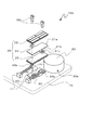
本実施形態に係るモーター100を示す、図1は分解斜視図、図2(a)は組立平面図、図2(b)は図2(a)のA−A´部の断面図である。図1および図2(a),(b)に示すように、モーター100は、基台10に回転可能に固定される被駆動体20と、基台10に摺動可能に固定される支持体40と、支持体40を被駆動体20側に付勢する付勢手段としてのコイルばね60と、付勢される支持体40に固定され振動によって被駆動体20を駆動するアクチュエーター30と、を備えている。
(First embodiment)
FIG. 1 is an exploded perspective view, FIG. 2A is an assembly plan view, and FIG. 2B is a cross-sectional view taken along the line AA ′ of FIG. As shown in FIG. 1 and FIGS. 2A and 2B, the
アクチュエーター30は、電極が形成された矩形の圧電体からなる圧電素子32,33が、振動板31を挟持するように貼り合わされて形成される。圧電素子32,33は圧電性を有する材料、例えば、チタン酸ジルコン酸鉛<PZT:Pb(Zr,Ti)O3>、水晶、ニオブ酸リチウム(LiNbO3)などが挙げられ、特にPZTが好適に用いられる。また形成される電極は、Au,Ti,Agなどの導電性金属を蒸着、スパッタリングなどにより成膜して形成することができる。振動板31は、アクチュエーター30として支持体40に固定されコイルばね60によって被駆動体20へ付勢され、被駆動体20と接する突起31aを端部に備えている。なお、振動板31は、ステンレス、ニッケル、ゴムメタルなどで形成され、加工性の容易さからステンレスが好適に用いられる。アクチュエーター30は、振動板31に形成された支持体40へ装着するための装着部31bの孔31cを挿通し、支持体40に形成された固定部40aのねじ孔40bとねじ嵌合するねじ50によって、支持体40に固定される。
The
被駆動体20は、円柱状の形状を成し、円柱面20aにアクチュエーター30の突起31aがコイルばね60によって付勢されて接触し、アクチュエーター30の振動によって駆動される。また、図2(b)に示すように被駆動体20に固定された回転軸21、および軸受け12などから構成される回転手段により基台10に固定される。回転軸21の回転力は、回転軸21に接続される図示されない減速あるいは増速装置200を介して所望の回転数、あるいは出力トルクによって被駆動装置を駆動する。
The driven
支持体40は、ガイド孔40cを備え、基台10に備えるガイドピン70がガイド孔40cに挿通され、支持体40は基台10に摺動可能に固定される。ガイド孔40cの形状は、本実施形態ではトラック状の平面形状を成し、アクチュエーター30の付勢方向に支持体40が摺動可能となっており、アクチュエーター30の付勢方向に交差する方向ではガイドピン70のガイド部外径よりわずかに大きくし、アクチュエーター30の付勢方向に交差する方向のガタ量を最小にする形状となっている。
The
また、支持体40には付勢手段としてのコイルばね60の一方の端部が、アクチュエーター30を装着する2ヵ所の固定部40aにそれぞれ装着されている。コイルばね60の他方の端部は基台10に備えるばね装着部11に装着され、支持体40が被駆動体20の方向に付勢される。支持体40には、アクチュエーター30の振動板31の装着部31bを支持体40の固定部40aに載置し、固定部40aに設けたねじ孔40bにねじ50によってアクチュエーター30が固定される。固定されたアクチュエーター30の突起31aは、支持体40を介して被駆動体20に所定の力で付勢される。なお、付勢手段としてはコイルばね60に限定されず、例えば、板ばね、弾性ゴムなどを用いても良い。
In addition, one end of a
次にアクチュエーター30の動作について図3を用いて説明する。図3(a),(b)はアクチュエーター30の振動動作を示す概略平面図である。図3(a)に示すように、圧電素子32に形成された電極32a,32b,32c,32d,32eのうち、電極32c,32b,32dと、図示されない圧電体を挟んで反対側に形成された電極との間に交流電圧を印加することにより、電極32c,32b,32dが形成される領域の圧電体は図示矢印方向の縦振動が励振される。電極32bの領域では図示矢印方向にアクチュエーター30を縦振動させ、電極32c,32dの領域ではアクチュエーター30を形状Mで示す屈曲振動を励起し、振動板31の突起31aは楕円軌跡S1を描いて振動する。
Next, the operation of the
また、図3(b)に示すように、圧電素子32に形成された電極32a,32b,32c,32d,32eのうち、電極32a,32b,32eと、図示されない圧電体を挟んで反対側に形成された電極との間に交流電圧を印加することにより、電極32a,32b,32eが形成される領域の圧電体は図示矢印方向の縦振動が励振される。電極32bの領域では図示矢印方向にアクチュエーター30を縦振動させ、電極32a,32eの領域ではアクチュエーター30を形状Nで示す屈曲振動を励起し、振動板31の突起31aは楕円軌跡S2を描いて振動する。
As shown in FIG. 3B, among the
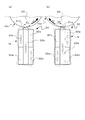
上述のアクチュエーター30の振動によって生じる突起31aの楕円軌跡S1,S2が、付勢力によって被駆動体20に付勢されて接触し、被駆動体20を図示矢印s1,s2方向に駆動する。この楕円軌跡S1,S2と、被駆動体20と、付勢手段としてのコイルばね60および支持体40と、の関係について図4を用いて説明する。
The elliptical trajectories S1 and S2 of the
図4(a)は、図3(a)に示す楕円軌跡S1を用いた説明概念図である。図2に示すように被駆動体20の回転中心をR、コイルばね60が支持体40の固定部40aを付勢する付勢点をQR,QLとした場合、被駆動体20とアクチュエーター30とは図4(a)に示すような関係にすることが好ましい。
FIG. 4A is an explanatory conceptual diagram using the elliptical locus S1 shown in FIG. As shown in FIG. 2, when the rotation center of the driven
図4に示すように、アクチュエーター30の突起31aが描く楕円軌跡S1は、被駆動体20の外形の円柱面20aに対して図示ハッチング部のオーバーラップBを形成した軌跡を描く。オーバーラップBは、モーター100の駆動の際には、コイルばね60の変位、アクチュエーター30および被駆動体20の素材の変形、などにより実態的には重なるものではない。この楕円軌跡S1を、楕円軌跡S1の中心と被駆動体20の回転中心Rとを結ぶ直線LCに沿って、被駆動体20の円柱面20aと楕円軌跡S1の軌跡図形が接するまで移動したときの楕円軌跡図形を、楕円軌跡S1´とする。この楕円軌跡S1´と被駆動体20の円柱面20aとの接点を接点Pと定義する。
As shown in FIG. 4, the elliptical locus S <b> 1 drawn by the
被駆動体20の回転中心Rと接点Pとを結ぶ直線を直線L1、接点Pと付勢点QRとを結ぶ直線を直線L2、とし、付勢手段としてのコイルばね60による付勢力Fの図示する付勢方向に平行で接点Pを通る直線L3と直線L1とでなす角度θ1と、直線L3と直線L2とでなす角度θ2と、が次の関係であることが好ましい。
θ1<θ2 (1)
The straight line L1 and straight line connecting the rotational center R and the contact P of the driven
θ1 <θ2 (1)
図4(b)は、接点Pにおける付勢力Fと、被駆動体20の円柱面20aからアクチュエーター30の突起31aに作用する反力FRによる力の関係を説明する概念図である。図4(b)に示すように、付勢力Fは直線L2に沿った分力と直線L3に直交する分力f1とに分解できる。また、反力FRは直線L3の分力と付勢方向に直交する分力fR1に分解できる。θ1およびθ2が式1の関係にあることから、
f1>fR1
となり、コイルばね60による付勢力Fを、突起31aを被駆動体20の回転中心R方向側に付勢するようにf1とfR1との差分が作用する。
4 (b) is a conceptual diagram illustrating the biasing force F at the contact point P, and the force of the relationship due to the reaction force F R exerted by the
f1>
Next, the biasing force F of the
すなわち式1に示すθ1,θ2の関係を備えることにより、反力FRによって生じる突起31aを回転中心Rに向かわせない付勢力の分力fR1を抑制し、アクチュエーター30に励起させる振動を高い効率で被駆動体20の回転力に変換することができる。
In other words, by providing the relationship of θ1 and θ2 shown in
図4(c)は、
θ1´>θ2 (2)
の関係の場合を説明する概念図である。なお、図4(c)および式2におけるθ1´は、図4(b)および式1に示すθ1に相当する。図4(c)に示すように、式2で表されるθ1´,θ2の関係の場合、反力FR´の直線L3に直交する分力fR1´は、
f1<fR1´
となり、式2に示すθ1´,θ2の関係になってしまうと、反力FR´によって生じる突起31aを回転中心R方向に向かわせない付勢力の分力fR1´を付勢力Fの分力f1によって抑制できず、アクチュエーター30に励起させる振動を被駆動体20の回転力に変換する効率を大きく損なうこととなる。なお、図3(b)に示す楕円軌跡S2の場合であっても、上述と同様に、付勢点QRを図2に示す付勢点QLに置き換えるだけのため、説明は省略する。
FIG. 4 (c)
θ1 ′> θ2 (2)
It is a conceptual diagram explaining the case of this relationship. Note that θ1 ′ in FIG. 4C and
f1 <
When the relationship of θ1 ′ and θ2 shown in
上述の楕円軌跡S1,S2は、次の方法によって計測することができる。本実施形態に係るモーター100を駆動させ、測定装置300(光ヘテロダイン微小振動測定装置MLD−103A:ネオアーク株式会社製)によって、突起31aに図2(b)に示す方向に照射されたレーザー光Kの反射光を測定装置300に受光し、測定装置300によって計測されたデータをオシロスコープ(YOKOGAWA DL−716:横河電気株式会社製)に波形表示、またはコンピューターによりデータ処理して楕円軌跡S1,S2を計測することができる。
The above-described elliptical trajectories S1 and S2 can be measured by the following method. The
このように計測された楕円軌跡S1,S2を確認しながら、アクチュエーター30の圧電素子32,33の各寸法、駆動電圧、コイルばね60の付勢力、アクチュエーター30の配置位置、圧電素子32,33の材料、被駆動体20の材料や円柱面20aの表面仕上げ、などを変えながら式1の条件を満たすモーター100を製作する。
While confirming the elliptical trajectories S1 and S2 measured in this way, the dimensions of the
また、図5(a),(b)に示すような付勢手段の配置によって、式1におけるθ2を大きくすることができ、容易に図4および式1に示すθ1の自由度を高めることができる。図5(a)に示すモーター110では、支持体41の固定部41aがアクチュエーター30Aの突起31Aaに近い位置に配置、すなわちC寸法を、図2に示すモーター100より小さくして配置されている。これにより、θ2に近似する角度αがより大きくなり、大きなθ2を得ることができることで、θ1の自由度を拡大することができる。
Further, by arranging the urging means as shown in FIGS. 5A and 5B, θ2 in
また図5(b)に示すモーター120では、コイルばね60の支持体42の固定部42aに対する付勢点をアクチュエーター30Aの突起31Aa位置より被駆動体20の回転中心側のC´位置に配置した。このように配置することで、図4に示すθ1を決めるためのアクチュエーター30Aの圧電素子の各寸法、駆動電圧、コイルばね60の付勢力、アクチュエーター30Aの配置位置、圧電素子の材料、被駆動体20の材料や円柱面20aの表面仕上げ、などに対する制約は大幅に緩和することができる。
Further, in the
(第2実施形態)
図6は、第2実施形態に係るモーター100を備えたロボットハンド1000を示す外観図である。ロボットハンド1000は基部1100と、基部1100に接続された指部1200とを備えている。基部1100と指部1200との接続部1300と、指部1200の関節部1400とには、モーター100が組み込まれている。モーター100が駆動することによって、指部1200が屈曲し、物体を把持することができる。超小型モーターであるモーター100を用いることによって、小型でありながら多数のモーターを備えるロボットハンドを実現することができる。
(Second Embodiment)
FIG. 6 is an external view showing a
(第3実施形態)
図7は、ロボットハンド1000を備えるロボット2000の構成を示す図である。ロボット2000は、本体部2100、アーム部2200およびロボットハンド1000等から構成されている。本体部2100は、例えば床、壁、天井、移動可能な台車の上などに固定される。アーム部2200は、本体部2100に対して可動に設けられており、本体部2100にはアーム部2200を回転させるための動力を発生させる図示しないアクチュエーターや、アクチュエーターを制御する制御部等が内蔵されている。
(Third embodiment)
FIG. 7 is a diagram illustrating a configuration of a
アーム部2200は、第1フレーム2210、第2フレーム2220、第3フレーム2230、第4フレーム2240および第5フレーム2250から構成されている。第1フレーム2210は、回転屈折軸を介して、本体部2100に回転可能または屈折可能に接続されている。第2フレーム2220は、回転屈折軸を介して、第1フレーム2210および第3フレーム2230に接続されている。第3フレーム2230は、回転屈折軸を介して、第2フレーム2220および第4フレーム2240に接続されている。第4フレーム2240は、回転屈折軸を介して、第3フレーム2230および第5フレーム2250に接続されている。第5フレーム2250は、回転屈折軸を介して、第4フレーム2240に接続されている。アーム部2200は、制御部の制御によって、各フレーム2210〜2250が各回転屈折軸を中心に複合的に回転または屈折し動く。
The
アーム部2200の第5フレーム2250のうち第4フレーム2240が設けられた他方には、ロボットハンド接続部2300が接続されており、ロボットハンド接続部2300にロボットハンド1000が取り付けられている。ロボットハンド接続部2300にはロボットハンド1000に回転動作を与えるモーター100が内蔵され、ロボットハンド1000は対象物を把持することができる。小型、軽量のロボットハンド1000を用いることによって、汎用性が高く、複雑な電子機器の組み立て作業や検査等が可能なロボットを提供することができる。
The robot
10…基台、20…被駆動体、30…アクチュエーター、40…支持体、50…ねじ、60…コイルばね、70…ガイドピン、100…モーター。
DESCRIPTION OF
Claims (3)
前記被駆動手段の前記回転面に付勢する突起を端部に有する振動板と、前記振動板に積層される圧電体と、を有するアクチュエーターと、
前記アクチュエーターを前記被駆動手段に付勢する付勢手段と、を備えるモーターであって、
前記被駆動手段を駆動させる前記アクチュエーターの振動によって描かれる前記突起の楕円軌跡を、前記回転面と接するように配置し、前記楕円軌跡と前記回転面との接点を接点P、前記アクチュエーターに前記付勢手段による付勢力が作用する作用点を作用点Q、前記被駆動手段の回転中心を回転中心R、とした場合、
前記付勢手段の付勢方向と、前記回転中心Rと前記接点Pとを結ぶ方向と、でなす角度θ1と、
前記付勢手段の付勢方向と、前記接点Pと前記作用点Qを結ぶ方向と、でなす角度θ2と、は、
θ1<θ2
である、
ことを特徴とするモーター。 Driven means having a cylindrical rotating surface;
An actuator having a diaphragm having at its end a projection for urging the rotating surface of the driven means, and a piezoelectric body laminated on the diaphragm;
A biasing means for biasing the actuator to the driven means,
An elliptical locus of the protrusion drawn by vibration of the actuator that drives the driven means is disposed so as to contact the rotating surface, and a contact point between the elliptical locus and the rotating surface is a contact P, and the actuator is attached to the actuator. When the point of action where the biasing force by the biasing means acts is the point of action Q, and the center of rotation of the driven means is the center of rotation R,
An angle θ1 formed by an urging direction of the urging means and a direction connecting the rotation center R and the contact P;
The angle θ2 formed by the urging direction of the urging means and the direction connecting the contact point P and the action point Q is:
θ1 <θ2
Is,
A motor characterized by that.
Priority Applications (2)
| Application Number | Priority Date | Filing Date | Title |
|---|---|---|---|
| JP2011125103A JP2012253921A (en) | 2011-06-03 | 2011-06-03 | Motor, robot hand and robot |
| US13/484,738 US20120308355A1 (en) | 2011-06-03 | 2012-05-31 | Motor, robot hand, and robot |
Applications Claiming Priority (1)
| Application Number | Priority Date | Filing Date | Title |
|---|---|---|---|
| JP2011125103A JP2012253921A (en) | 2011-06-03 | 2011-06-03 | Motor, robot hand and robot |
Publications (2)
| Publication Number | Publication Date |
|---|---|
| JP2012253921A true JP2012253921A (en) | 2012-12-20 |
| JP2012253921A5 JP2012253921A5 (en) | 2014-07-10 |
Family
ID=47261820
Family Applications (1)
| Application Number | Title | Priority Date | Filing Date |
|---|---|---|---|
| JP2011125103A Withdrawn JP2012253921A (en) | 2011-06-03 | 2011-06-03 | Motor, robot hand and robot |
Country Status (2)
| Country | Link |
|---|---|
| US (1) | US20120308355A1 (en) |
| JP (1) | JP2012253921A (en) |
Cited By (1)
| Publication number | Priority date | Publication date | Assignee | Title |
|---|---|---|---|---|
| JP2016078208A (en) * | 2014-10-22 | 2016-05-16 | セイコーエプソン株式会社 | robot |
Families Citing this family (5)
| Publication number | Priority date | Publication date | Assignee | Title |
|---|---|---|---|---|
| CN106826800A (en) * | 2015-12-28 | 2017-06-13 | 苏州大学 | Selective compliance assembly robot arm and its control system |
| JP7151166B2 (en) * | 2018-05-18 | 2022-10-12 | セイコーエプソン株式会社 | Grasping device and robot |
| JP2019213255A (en) * | 2018-05-31 | 2019-12-12 | セイコーエプソン株式会社 | Rotation-linear motion conversion device |
| CN110254808B (en) * | 2019-07-03 | 2021-07-30 | 哈工大机器人集团(哈尔滨)华粹智能装备有限公司 | Fiber wool ball weighing gripper and working method |
| WO2021139145A1 (en) * | 2020-01-07 | 2021-07-15 | 北京可以科技有限公司 | Mechanical arm device |
Citations (3)
| Publication number | Priority date | Publication date | Assignee | Title |
|---|---|---|---|---|
| JP2003070270A (en) * | 2001-08-29 | 2003-03-07 | Seiko Epson Corp | Wire actuator |
| JP2006271065A (en) * | 2005-03-23 | 2006-10-05 | Konica Minolta Opto Inc | Driving device |
| JP2010233335A (en) * | 2009-03-26 | 2010-10-14 | Seiko Epson Corp | Piezoelectric motor, liquid jetting device, and timepiece |
Family Cites Families (5)
| Publication number | Priority date | Publication date | Assignee | Title |
|---|---|---|---|---|
| US5726520A (en) * | 1993-08-02 | 1998-03-10 | Bonneville Scientific Incorporated | Direct drive field actuator motors |
| JP2007221865A (en) * | 2006-02-14 | 2007-08-30 | Seiko Epson Corp | Piezoelectric vibrator, adjusting method for natural frequency of piezoelectric vibrator, piezoelectric actuator, and electronic apparatus |
| JP4209463B2 (en) * | 2007-03-15 | 2009-01-14 | パナソニック株式会社 | Ultrasonic actuator |
| JP2010233339A (en) * | 2009-03-26 | 2010-10-14 | Seiko Epson Corp | Piezoelectric motor, liquid jetting device and timepiece |
| JP5382320B2 (en) * | 2009-03-26 | 2014-01-08 | セイコーエプソン株式会社 | Piezoelectric motor, liquid ejecting apparatus and clock |
-
2011
- 2011-06-03 JP JP2011125103A patent/JP2012253921A/en not_active Withdrawn
-
2012
- 2012-05-31 US US13/484,738 patent/US20120308355A1/en not_active Abandoned
Patent Citations (3)
| Publication number | Priority date | Publication date | Assignee | Title |
|---|---|---|---|---|
| JP2003070270A (en) * | 2001-08-29 | 2003-03-07 | Seiko Epson Corp | Wire actuator |
| JP2006271065A (en) * | 2005-03-23 | 2006-10-05 | Konica Minolta Opto Inc | Driving device |
| JP2010233335A (en) * | 2009-03-26 | 2010-10-14 | Seiko Epson Corp | Piezoelectric motor, liquid jetting device, and timepiece |
Cited By (1)
| Publication number | Priority date | Publication date | Assignee | Title |
|---|---|---|---|---|
| JP2016078208A (en) * | 2014-10-22 | 2016-05-16 | セイコーエプソン株式会社 | robot |
Also Published As
| Publication number | Publication date |
|---|---|
| US20120308355A1 (en) | 2012-12-06 |
Similar Documents
| Publication | Publication Date | Title |
|---|---|---|
| JP5776270B2 (en) | Piezoelectric actuators, motors, robot hands and robots | |
| JP2012253921A (en) | Motor, robot hand and robot | |
| JP2012235622A (en) | Motor, robot hand, and robot | |
| JP5765993B2 (en) | Vibration type driving device | |
| JP2004320979A (en) | Driving device and electric equipment | |
| JP2014018027A (en) | Vibration type actuator, imaging apparatus, and stage | |
| JP2005081538A (en) | Manipulator and device equipped with it | |
| JP6269223B2 (en) | Piezoelectric motor | |
| JP6605012B2 (en) | Vibration wave motor and lens driving device using vibration wave motor | |
| JP2020018079A (en) | Piezoelectric drive device, robot and printer | |
| JP2012210053A (en) | Piezoelectric actuator, robot, and robot hand | |
| JP5803294B2 (en) | Motor, robot hand and robot | |
| JP2019082625A (en) | Optical reflection element | |
| WO2016002917A1 (en) | Vibration-type actuator, lens barrel, image-capturing device, and automatic stage | |
| US11888416B2 (en) | Piezoelectric drive device and robot | |
| JP6269224B2 (en) | Piezoelectric motor | |
| JP4316350B2 (en) | Ultrasonic motor and electronic device with ultrasonic motor | |
| JP2022117611A (en) | Piezoelectric drive device and robot | |
| JP2022011405A (en) | Piezoelectric drive device, piezoelectric motor, and robot | |
| JP2022112669A (en) | Piezoelectric drive device and robot | |
| JP2003070270A (en) | Wire actuator | |
| CN116260359A (en) | Piezoelectric driving device and robot | |
| JP2021191049A (en) | Piezoelectric drive device, piezoelectric motor and robot | |
| JP6269222B2 (en) | Piezoelectric motor | |
| JP2022070448A (en) | Piezoelectric drive device and robot |
Legal Events
| Date | Code | Title | Description |
|---|---|---|---|
| A521 | Written amendment |
Free format text: JAPANESE INTERMEDIATE CODE: A523 Effective date: 20140526 |
|
| A621 | Written request for application examination |
Free format text: JAPANESE INTERMEDIATE CODE: A621 Effective date: 20140526 |
|
| RD04 | Notification of resignation of power of attorney |
Free format text: JAPANESE INTERMEDIATE CODE: A7424 Effective date: 20150107 |
|
| A131 | Notification of reasons for refusal |
Free format text: JAPANESE INTERMEDIATE CODE: A131 Effective date: 20150127 |
|
| A977 | Report on retrieval |
Free format text: JAPANESE INTERMEDIATE CODE: A971007 Effective date: 20150130 |
|
| A761 | Written withdrawal of application |
Free format text: JAPANESE INTERMEDIATE CODE: A761 Effective date: 20150224 |