JP2012251756A - Refrigerator - Google Patents
Refrigerator Download PDFInfo
- Publication number
- JP2012251756A JP2012251756A JP2011127160A JP2011127160A JP2012251756A JP 2012251756 A JP2012251756 A JP 2012251756A JP 2011127160 A JP2011127160 A JP 2011127160A JP 2011127160 A JP2011127160 A JP 2011127160A JP 2012251756 A JP2012251756 A JP 2012251756A
- Authority
- JP
- Japan
- Prior art keywords
- cooler
- defrosting
- heater
- energization
- cold air
- Prior art date
- Legal status (The legal status is an assumption and is not a legal conclusion. Google has not performed a legal analysis and makes no representation as to the accuracy of the status listed.)
- Granted
Links
Images


Abstract
Description
本発明の実施形態は、冷蔵庫に関する。 Embodiments of the present invention relate to a refrigerator.
冷蔵庫では、被貯蔵物を冷却するための冷却器に霜が付着するが、霜が冷却器に付着すると、冷却器の冷却能力が低下する。従って、このような冷却器に付着した霜を除去することが冷蔵庫の性能向上のためには重要であり、このような霜を除去するために、冷却器に除霜用ヒータが設けられ、この除霜用ヒータで冷却器に付着した霜を融解して除霜している。 In the refrigerator, frost adheres to the cooler for cooling the storage object. However, when the frost adheres to the cooler, the cooling capacity of the cooler decreases. Therefore, it is important to remove the frost adhering to such a cooler in order to improve the performance of the refrigerator. In order to remove such frost, a heater for defrosting is provided in the cooler. The frost adhering to the cooler is melted and defrosted with a heater for defrosting.
除霜用ヒータとしては、例えば金属パイプ内にヒータ線を封入したシーズヒータなどからなる長尺のパイプヒータやガラス管ヒータが使用されている。ガラス管ヒータは、冷却器に対する加温が間接的なものである。 As the defrosting heater, for example, a long pipe heater or a glass tube heater composed of a sheathed heater in which a heater wire is enclosed in a metal pipe is used. The glass tube heater is indirectly heated with respect to the cooler.
冷却器に付着した霜を除去する除霜用ヒータは、従来、1台の冷却器に対して1個のみ設けられ、この1個の除霜用ヒータで冷却器を全体的に加温して冷却器に付着した霜を除去している。従って、この1個の除霜用ヒータにより冷却器の除霜を行っている場合においては、霜が早く溶けて除霜が早く完了している部分と霜がなかなか溶けず除霜完了が遅い部分などが冷却器に存在するが、従来は、除霜用ヒータに対する通電は、除霜完了が遅い部分の霜が除去され、冷却器全体が完全に除霜されるまで行っているため、除霜完了が遅い部分の霜が完全に除去されるまで、除霜が早く完了している部分に対しても通電が無駄に継続して行われ、無駄な電力消費が発生し、非経済的であるとともに、冷却器が必要以上に加温されるなどという無駄があり、非効率的であるという問題がある。 Conventionally, only one defrosting heater for removing frost adhering to the cooler is provided for one cooler, and the entire cooler is heated by the one defrosting heater. The frost attached to the cooler is removed. Therefore, in the case where the cooler is defrosted by this one defrosting heater, the part where the frost melts quickly and the defrosting is completed early and the part where the frost does not melt easily and the defrosting is late However, in the past, energization of the heater for defrosting is performed until the frost in the part where defrosting is late is removed and the entire cooler is completely defrosted. Until the frost in the part where the completion is late is completely removed, the part where the defrosting is completed early is continuously conducted unnecessarily, resulting in unnecessary power consumption and being uneconomical. In addition, there is a problem that the cooler is heated more than necessary, which is inefficient.
本発明は、上記に鑑みてなされたもので、その目的とするところは、除霜用ヒータに対する消費電力を低減しながら冷却器に付着した霜を効率的に除去し得る冷蔵庫を提供することにある。 The present invention has been made in view of the above, and an object of the present invention is to provide a refrigerator capable of efficiently removing frost attached to a cooler while reducing power consumption for a defrosting heater. is there.
請求項1記載の冷蔵庫は、貯蔵室内に冷気を循環させて該貯蔵室内の貯蔵物を冷却する冷却器と、前記貯蔵室からの冷気を冷却器に循環する戻り冷気用開口と、この戻り冷気用開口の位置に対応して分割して冷却器に設けられ該冷却器に付着した霜を除去する複数の除霜用ヒータと、この複数の除霜用ヒータに対する通電を前記戻り冷気用開口に近接した冷却器に設けられる除霜用ヒータに対する通電を多くするように個々に制御する通電制御手段とを有することを要旨とする。
The refrigerator according to
以下、図面を用いて、本発明を実施するための形態(以下、実施形態と称する)を説明する。 DESCRIPTION OF EMBODIMENTS Hereinafter, embodiments for carrying out the present invention (hereinafter referred to as embodiments) will be described with reference to the drawings.
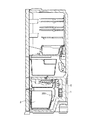
図1は、本発明の第1の実施形態に係わる冷蔵庫を示す縦断面図である。本実施形態においては、冷蔵室、野菜室、製氷室及び冷凍庫を含む貯蔵室のうち、一例として冷凍室について説明する。 FIG. 1 is a longitudinal sectional view showing a refrigerator according to the first embodiment of the present invention. In the present embodiment, a freezer room will be described as an example among storage rooms including a refrigerator room, a vegetable room, an ice making room, and a freezer.
同図に示す冷蔵庫は、その最下部に設けられている冷凍室3の裏側(背面側)の冷却室内に冷却器1が設けられ、この冷却器1の真上には、ファン5が設けられている。そして、冷却器1で冷却された冷気は、ファン5によって冷凍室3内に送り込まれて冷凍室3内を冷却するようになっている。
The refrigerator shown in the figure is provided with a
また、冷凍室3内を冷却した後の冷凍室3から循環して戻ってきた冷気、つまり戻り冷気は、図1において矢印201で示すように冷凍室3の後部から冷却室内に戻り冷気用開口を介して排出され、冷却室内を上方へ通過する間に、再度冷却器1で冷却され、さらにファン5によって冷凍室3内に送り込まれるという循環動作を繰り返し行うようになっている。この戻り冷気用開口は冷却室に設けられる冷凍室3からの冷気の戻り口であれば良く、特に開口として孔が形成されたものであっても、冷凍室3との間の隙間様の開口であっても構わない。
Further, the cold air that has circulated and returned from the
図2は、図1に示す冷蔵庫に使用される冷却器1を示す斜視図である。この冷却器1は、アルミニウム材からなる長尺の冷却パイプ11に所定の間隔で短冊状のアルミニウム材の薄肉片からなる冷却フィン13を多数通して嵌着させ、これを蛇行形成して複数重ねることで外形を直方体状に形成するとともに、冷却フィン13の両端部における冷却パイプ11のU字状曲げ部にやや肉厚のアルミニウム材からなる端板15をそれぞれ配設して形状を保持するように構成されている。なお、冷却パイプ11が嵌め込まれるように設けられ、嵌装される冷却フィン13および端板15には、長めの開孔13aが形成され、この開孔13aに冷却パイプ11が挿通されている。
FIG. 2 is a perspective view showing a
このように構成される冷却器1の前側(図2で手前側)には、金属パイプの内部にヒータ線を封入したシーズヒータからなる長尺の前側除霜用パイプヒータ31が冷却器1の前側に対応して蛇行しながら平行に設けられている。
On the front side (front side in FIG. 2) of the
また、冷却器1の後側(図2で奥側)にも、同様に、金属パイプの内部にヒータ線を封入したシーズヒータからなる長尺の後側除霜用パイプヒータ33が冷却器1の後側に対応して蛇行しながら平行に設けられている。なお、この後側除霜用パイプヒータ33は、冷却器1の後側となって、図2では、一部しか見えないが、前側除霜用パイプヒータ31と同様に冷却器1の後側に蛇行しながら平行に設けられているものである。
Similarly, on the rear side of the cooler 1 (the back side in FIG. 2), a long rear defrosting
本実施形態においては、上述したように、前側除霜用パイプヒータ31と後側除霜用パイプヒータ33からなる複数(本実施形態では、2つ)の除霜用ヒータ(以下、除霜用パイプヒータを総称して、単に除霜用ヒータとも称する)を1台の冷却器1の前後方向の複数の部位(本実施形態では、冷却器1の前側と後側の2つの部位)のそれぞれに対応して設けるとともに、各除霜用ヒータに対する通電を別々に制御するための図示しない通電早期制御手段、通電長延長制御手段及び通電終了遅延制御手段を含む通電制御手段が設けられている。そして、この通電制御手段により各除霜用ヒータ31、33に対する通電を個々に制御し得るようにしている。
In the present embodiment, as described above, a plurality (two in the present embodiment) of defrosting heaters (hereinafter, defrosting heaters) including the front-side defrosting pipe heater 31 and the rear-side defrosting
すなわち、この各除霜用ヒータ31、33に対する通電を別々に制御し得る通電制御手段により、一方の除霜用ヒータのみに対して通電して、この一方の除霜用ヒータに対応する冷却器1の部位のみを加熱したり、他方の除霜用ヒータのみに対して通電して、この他方の除霜用ヒータに対応する冷却器1の部位のみを加熱したり、両方の除霜用ヒータに対して同時に通電して、両方の除霜用ヒータに対応する冷却器1の両方の部位を同時に加熱したり、または一方の除霜用ヒータに対して先に通電して、この一方の除霜用ヒータに対応する冷却器1の部位を先に加熱してから、次に他方の除霜用ヒータに対して通電して、この他方の除霜用ヒータに対応する冷却器1の部位を後から加熱したり、またはこの場合において、他方の除霜用ヒータに対する通電を一方の除霜用ヒータに対する通電よりも先に終了したり、または両方の除霜用ヒータに対して同時に通電して、この両方の除霜用ヒータに対応する冷却器1の両方の部位を同時に加熱してから、一方の除霜用ヒータに対する通電を他方の除霜用ヒータよりも先に終了するなどのように種々の制御が冷却器1における着霜状態に応じて可能になっている。
That is, the energization control means capable of separately controlling the energization of the defrosting
また、上述したように、冷凍室3を冷却した後の冷凍室3からの戻り冷気が冷凍室3の後部から排出され、この戻り冷気が冷却器1を通過して再度冷却される場合において、この戻り冷気が例えば、図2において矢印301で示すように、冷却器1の前側から冷却器1内に入り、冷却器1内に入った後、冷却器1内をファン5により上昇するように移動しながら冷却されるという場合には、この冷凍室3からの戻り冷気は、多少温度が上昇しているとともに多量の湿気を含んでいるため、冷却器1の前側から冷却器1内に入った場合には、この冷却器1の前側に対する着霜が多大となるものであるため、この冷却器1の前側の多大となる着霜を完全に除去することが重要である。
Further, as described above, when the return cold air from the
このために、本実施形態では、上記のような場合に、前側除霜用パイプヒータ31、すなわち冷却器1の戻り冷気用開口に近接した部位、若しくは戻り冷気用開口からの戻り冷気が当たる位置である前側に対応して設けられている前側除霜用パイプヒータ31に対する通電を通電早期制御手段により後側除霜用パイプヒータ33よりも早く行ったり、または前側除霜用パイプヒータ31に対する通電を通電長延長制御手段により後側除霜用パイプヒータ33よりも長く行ったり、または前側除霜用パイプヒータ31と後側除霜用パイプヒータ33の両方に対する通電を同時に行ったとしても、後側除霜用パイプヒータ33に対する通電を早く終了させ、前側除霜用パイプヒータ31に対する通電を通電終了遅延制御手段により遅らせて更に長く継続させることなどにより、冷却器1の戻り冷気用開口に近接した部位である前側における除霜を完全に行うとともに、冷却器全体に対する除霜を完全に行うように前記通電終了遅延制御手段、通電早期制御手段、通電長延長制御手段、通電停止制御手段などにより前記通電制御手段を制御している。
For this reason, in this embodiment, in the above case, the front defrosting pipe heater 31, that is, the position close to the return cold air opening of the
このように除霜用ヒータに対する通電制御を個別に行い得るようにすることにより、冷却器1の除霜を効率的かつ経済的に行うことができる。すなわち、上述したように、戻り冷気が入る冷却器1の前側には多大の着霜が発生し、この着霜の除去には時間がかかるものであるが、冷却器1の後側の着霜は比較的少ないものであるため、冷却器1の後側の除霜は、比較的短時間で行わるものである。従って、この冷却器1の後側に対する通電を前側よりも短くすることにより、消費電力を低減できるものである。
Thus, by making it possible to individually control energization for the defrosting heater, defrosting of the
図3は、本発明の第2の実施形態に使用される冷却器10を示す斜視図である。同図に示す冷却器10も、図2に示した第1の実施形態の冷却器1と同様に図1に示すような冷蔵庫の冷凍室3の後側に設けられ、この冷却器10の真上にはファン5が設けられているものである。
FIG. 3 is a perspective view showing the cooler 10 used in the second embodiment of the present invention. Similarly to the
図3において、本実施形態の冷却器10は、図2に示した前側除霜用パイプヒータ31と後側除霜用パイプヒータ33からなる2つの除霜用ヒータに代わって、左前側除霜用パイプヒータ41a、右前側除霜用パイプヒータ43a、左後側除霜用パイプヒータ41bおよび右後側除霜用パイプヒータ43bからなる4つの除霜用ヒータを当該冷却器10の冷却フィン13の前側(図3で手前側)の左右と後側(図3で奥側)の左右にそれぞれ対応して蛇行しながら平行に設けている点が異なるものであり、その他の構成および作用は、同じであり、同じ構成要素には同じ符号を付している。
In FIG. 3, the cooler 10 of this embodiment replaces the two defrosting heaters including the front-side defrosting pipe heater 31 and the rear-side
すなわち、左前側除霜用パイプヒータ41aは、冷却器10の冷却フィン13の前側の左側に対応して蛇行しながら平行に設けられ、右前側除霜用パイプヒータ43aは、冷却器10の冷却フィン13の前側の右側に対応して蛇行しながら平行に設けられ、左後側除霜用パイプヒータ41bは、冷却器10の冷却フィン13の後側の左側に対応して蛇行しながら平行に設けられ、右後側除霜用パイプヒータ43bは、冷却器10の冷却フィン13の後側の右側に対応して蛇行しながら平行に設けられている。なお、左後側除霜用パイプヒータ41bは、図3では冷却器10の後側となって、一部しか見えないが、左前側除霜用パイプヒータ41aと同様に冷却器10の後側の左に蛇行しながら設けられているものであり、また右後側除霜用パイプヒータ43bも、図3では冷却器10の後側となって、見えないが、右前側除霜用パイプヒータ43aと同様に冷却器10の後側の右に蛇行しながら設けられているものである。
That is, the left front
本実施形態においては、上述したように、左前側除霜用パイプヒータ41a、左後側除霜用パイプヒータ41b、右前側除霜用パイプヒータ43a、右後側除霜用パイプヒータ43bからなるからなる複数(本実施形態では、4つ)の除霜用ヒータ41a、41b、43a、43b(以下、除霜用パイプヒータを総称して、単に除霜用ヒータとも称する)を1台の冷却器10の前側と後側のそれぞれの左と右の複数の部位、すなわち冷却器の左右方向の複数の部位(本実施形態では、左側部位と右側部位の2つの部位)のそれぞれに対応して設けるとともに、各部位に対応して設けられている各除霜用ヒータに対する通電を個別に制御するための図示しない通電制御手段が設けられている。そして、この通電制御手段により各除霜用ヒータ41a、41b、43a、43bに対する通電を別々に制御し得るようにしている。
In the present embodiment, as described above, the left front
すなわち、この別々に制御し得る通電制御手段により、4つの除霜用ヒータ41a、41b、43a、43bのうち、左前側除霜用パイプヒータ41aと左後側除霜用パイプヒータ41bからなる前後の左側の2つの除霜用ヒータ41a、41b(以下、この左側の2つの除霜用ヒータ41a、41bを総称して、左側除霜用ヒータ41とも称する)のみに対して通電して、この左側除霜用ヒータ41に対応する冷却器10の左側の部位のみを加熱したり、または逆に右前側除霜用パイプヒータ43aと右後側除霜用パイプヒータ43bからなる前後の右側の2つの除霜用ヒータ43a、43b(以下、この右側の2つの除霜用ヒータ43a、43bを総称して、右側除霜用ヒータ43とも称する)のみに対して通電して、この右側除霜用ヒータ43に対応する冷却器10の右側の部位のみを加熱したり、または左側除霜用ヒータ41および右側除霜用ヒータ43のうちの一方の除霜用ヒータに対して先に通電して、この一方の除霜用ヒータに対応する冷却器10の部位を先に加熱してから、次に他方の除霜用ヒータに対して通電して、この他方の除霜用ヒータに対応する冷却器10の部位を後から加熱したり、またはこの場合において、他方の除霜用ヒータに対する通電を一方の除霜用ヒータに対する通電よりも先に終了したり、または左側除霜用ヒータ41および右側除霜用ヒータ43の両方の除霜用ヒータに対して同時に通電して、この両方の除霜用ヒータに対応する冷却器10の両方の部位を同時に加熱してから、一方の除霜用ヒータに対する通電を他方の除霜用ヒータよりも先に終了するなどのように種々の制御が冷却器10における着霜状態に応じて可能になっている。
That is, before and after the
また、冷凍室3を冷却した後の冷凍室3からの戻り冷気が冷凍室3の後部から排出され、この戻り冷気が冷却器10を通過して再度冷却される場合において、この戻り冷気が例えば、図3において矢印401で示すように、冷却器10の左側から冷却器10内に入り、冷却器10内に入った後、冷却器10内をファン5により上昇するように移動しながら冷却されるという場合には、この冷凍室3からの戻り冷気は、多少温度が上昇しているとともに多量の湿気を含んでいるため、冷却器10の左から冷却器10内に入った場合には、この冷却器10の左側に対する着霜が多大となるものであるため、この冷却器10の左側の多大となる着霜を完全に除去することが重要である。
In addition, when the return cold air from the
そこで、本実施形態では、上記のような場合に、左側除霜用ヒータ41、すなわち冷却器10の戻り冷気用開口に近接した部位である左側に対応して設けられている左側除霜用ヒータ41に対する通電を通電早期制御手段により右側除霜用ヒータ43よりも早く行ったり、または左側除霜用ヒータ41に対する通電を通電長延長制御手段により右側除霜用ヒータ43よりも長く行ったり、または左側除霜用ヒータ41と右側除霜用ヒータ43の両方に対する通電を同時に行ったとしても、右側除霜用ヒータ43に対する通電を早く終了させ、左側除霜用ヒータ41に対する通電を通電終了遅延制御手段により遅らせて更に長く継続させることなどにより、冷却器10の戻り冷気用開口に近接した部位である左側における除霜を完全に行うとともに、冷却器全体に対する除霜を完全に行うように前記通電終了遅延制御手段、通電早期制御手段、通電長延長制御手段などにより前記通電制御手段を制御している。 Therefore, in the present embodiment, in the above case, the left defrosting heater 41, that is, the left defrosting heater provided corresponding to the left side that is a part close to the return cold air opening of the cooler 10. The energization to 41 is performed earlier than the right defrosting heater 43 by the energization early control means, the energization to the left defrosting heater 41 is performed longer than the right defrosting heater 43 by the energization length extension control means, or Even if energization of both the left defrosting heater 41 and the right defrosting heater 43 is performed simultaneously, the energization of the right defrosting heater 43 is quickly terminated and the energization of the left defrosting heater 41 is energized end delay control. If the defrosting is completely performed on the left side, which is a portion close to the return cold air opening of the cooler 10, by delaying the time by means and continuing for a longer time, etc. To the power distribution end delay control means so as to completely defrosted for the entire condenser, energization early control means controls the energization control means such as by energizing extender control means.
このように除霜用ヒータに対する通電制御を個別に行い得るようにすることにより、冷却器10の除霜を効率的かつ経済的に行うことができる。すなわち、戻り冷気が入る冷却器10の左側には多大の着霜が発生し、この着霜の除去には時間がかかるものであるが、冷却器10の右側の着霜は比較的少ないものであるため、冷却器10の右側の除霜を比較的短時間で少ない消費電力で行うものである。従って、この冷却器10の右側にある右側除霜用ヒータ43に対する通電を左側にある左側除霜用ヒータ41よりも短くすることにより、消費電力を低減できるものである。 Thus, by making it possible to individually control energization for the defrosting heater, the defrosting of the cooler 10 can be performed efficiently and economically. That is, a great amount of frost is generated on the left side of the cooler 10 where the return cold air enters, and it takes time to remove this frost, but the frost on the right side of the cooler 10 is relatively small. Therefore, the defrosting on the right side of the cooler 10 is performed in a relatively short time with a small amount of power consumption. Therefore, the power consumption can be reduced by making the energization to the right defrosting heater 43 on the right side of the cooler 10 shorter than the left defrosting heater 41 on the left side.
図4は、本発明の第3の実施形態に使用される冷却器100を示す斜視図である。同図に示す冷却器100も、図2および図3に示した第1および第2の実施形態の冷却器1および10と同様に図1に示すような冷蔵庫の冷凍室3の後側に設けられ、この冷却器100の真上にはファン5が設けられているものである。
FIG. 4 is a perspective view showing a cooler 100 used in the third embodiment of the present invention. The cooler 100 shown in the figure is also provided on the rear side of the
図4において、本実施形態の冷却器10は、図2に示した第1の実施形態の冷却器1の前側除霜用パイプヒータ31と後側除霜用パイプヒータ33からなる2つの除霜用ヒータに代わって、下前側除霜用パイプヒータ51a、下後側除霜用パイプヒータ51b、上前側除霜用パイプヒータ53aおよび上後側除霜用パイプヒータ53bからなる4つの除霜用ヒータを当該冷却器100の冷却フィン13の前側(図4で手前側)の上下と後側(図4で奥側)の上下にそれぞれ対応して蛇行しながら平行に設けている点が異なるものであり、その他の構成および作用は、同じであり、同じ構成要素には同じ符号を付している。
In FIG. 4, the cooler 10 of the present embodiment includes two defrosters including the front defrosting pipe heater 31 and the rear
すなわち、下前側除霜用パイプヒータ51aは、冷却器100の冷却フィン13の前側の下側に対応して蛇行しながら平行に設けられ、下後側除霜用パイプヒータ51bは、冷却器100の冷却フィン13の後側の下側に対応して蛇行しながら平行に設けられ、上前側除霜用パイプヒータ53aは、冷却器100の冷却フィン13の前側の上側に対応して蛇行しながら平行に設けられ、上後側除霜用パイプヒータ53bは、冷却器100の冷却フィン13の後側の上側に対応して蛇行しながら平行に設けられている。なお、下後側除霜用パイプヒータ51bおよび上後側除霜用パイプヒータ53bは、図4では冷却器10の後側となって、一部しか見えないが、それぞれ下前側除霜用パイプヒータ51aおよび上前側除霜用パイプヒータ53aと同様に冷却器10の後側の上下に蛇行しながら平行に設けられているものである。
That is, the lower front
本実施形態においては、上述したように、下前側除霜用パイプヒータ51a、下後側除霜用パイプヒータ51b、上前側除霜用パイプヒータ53a、上後側除霜用パイプヒータ53bからなるからなる複数(本実施形態では、4つ)の除霜用ヒータ51a、51b、53a、53b(以下、除霜用パイプヒータを総称して、単に除霜用ヒータとも称する)を1台の冷却器100の前側と後側のそれぞれの上下の複数の部位、すなわち冷却器の上下方向の複数の部位(本実施形態では、下側部位と上側部位の2つの部位)のそれぞれに対応して設けるとともに、各部位に対応して設けられている各除霜用ヒータに対する通電を別々に制御するための図示しない通電制御手段が設けられている。そして、この通電制御手段により各除霜用ヒータ51a、51b、53a、53bに対する通電を別々に制御し得るようにしている。
In the present embodiment, as described above, the lower front
すなわち、この別々に制御し得る通電制御手段により、4つの除霜用ヒータ51a、51b、53a、53bのうち、下前側除霜用パイプヒータ51aと下後側除霜用パイプヒータ51bからなる前後の下側の2つの除霜用ヒータ51a、51b(以下、この下側の2つの除霜用ヒータ51a、51bを総称して、下側除霜用ヒータ51とも称する)のみに対して通電して、この下側除霜用ヒータ51に対応する冷却器100の下側の部位のみを加熱したり、または逆に上前側除霜用パイプヒータ53aと上後側除霜用パイプヒータ53bからなる前後の上側の2つの除霜用ヒータ53a、53b(以下、この上側の2つの除霜用ヒータ53a、53bを総称して、上側除霜用ヒータ53とも称する)のみに対して通電して、この上側除霜用ヒータ53に対応する冷却器100の上側の部位のみを加熱したり、または下側除霜用ヒータ51および上側除霜用ヒータ53のうちの一方の除霜用ヒータに対して先に通電して、この一方の除霜用ヒータに対応する冷却器100の部位を先に加熱してから、次に他方の除霜用ヒータに対して通電して、この他方の除霜用ヒータに対応する冷却器100の部位を後から加熱したり、またはこの場合において、他方の除霜用ヒータに対する通電を一方の除霜用ヒータに対する通電よりも先に終了したり、または下側除霜用ヒータ51および上側除霜用ヒータ53の両方の除霜用ヒータに対して同時に通電して、この両方の除霜用ヒータに対応する冷却器100の両方の部位を同時に加熱してから、一方の除霜用ヒータに対する通電を他方の除霜用ヒータよりも先に終了するなどのように種々の制御が冷却器100における着霜状態に応じて可能になっている。
That is, by the energization control means that can be controlled separately, of the four
また、冷凍室3を冷却した後の冷凍室3からの戻り冷気が冷凍室3の後部から排出され、この戻り冷気が冷却器100を通過して再度冷却される場合において、この戻り冷気が例えば、図4において矢印501で示すように、冷却器100下側から冷却器100内に入り、冷却器100内に入った後、冷却器100内をファン5により上昇するように移動しながら冷却されるという場合には、この冷凍室3からの戻り冷気は、多少温度が上昇しているとともに多量の湿気を含んでいるため、冷却器100の下から冷却器100内に入った場合には、この冷却器100の下側に対する着霜が多大となるものであるため、この冷却器100の下側の多大となる着霜を完全に除去することが重要である。
Moreover, when the return cold air from the
そこで、本実施形態では、上記のような場合に、下側除霜用ヒータ51、すなわち冷却器100の戻り冷気用開口に近接した部位である下側に対応して設けられている下側除霜用ヒータ51に対する通電を通電早期制御手段により上側除霜用ヒータ53よりも早く行ったり、または下側除霜用ヒータ51に対する通電を通電長延長制御手段により上側除霜用ヒータ53よりも長く行ったり、または下側除霜用ヒータ51と上側除霜用ヒータ53の両方に対する通電を同時に行ったとしても、上側除霜用ヒータ53に対する通電を早く終了させ、下側除霜用ヒータ51に対する通電を通電終了遅延制御手段により遅らせて更に長く継続させることなどにより、冷却器100の戻り冷気用開口に近接した部位である下側における除霜を完全に行うとともに、冷却器全体に対する除霜を完全に行うように前記通電終了遅延制御手段、通電早期制御手段、通電長延長制御手段などにより前記通電制御手段を制御している。 Therefore, in this embodiment, in the above case, the lower side defrosting heater 51, that is, the lower side removal provided corresponding to the lower side that is a portion close to the return cold air opening of the cooler 100. The energization to the frost heater 51 is performed earlier than the upper defrosting heater 53 by the energization early control means, or the energization to the lower defrosting heater 51 is made longer than the upper defrosting heater 53 by the energization length extension control means. Even if power is supplied to both the lower defrosting heater 51 and the upper defrosting heater 53 at the same time, the power supply to the upper defrosting heater 53 is quickly terminated and the lower defrosting heater 51 is turned off. The defrosting is completely performed on the lower side of the cooler 100 in the vicinity of the return cold air opening by, for example, delaying the energization by the energization end delay control means and continuing the energization further. Both the power distribution end delay control means so as to completely defrosted for the entire condenser, energization early control means controls the energization control means such as by energizing extender control means.
このように除霜用ヒータに対する通電制御を個別に行い得るようにすることにより、冷却器100の除霜を効率的かつ経済的に行うことができる。すなわち、戻り冷気が入る冷却器100の下側には多大の着霜が発生し、この着霜の除去には時間がかかるものであるが、冷却器100の上側の着霜は比較的少ないものであるため、冷却器1の上側の除霜を比較的短時間で少ない消費電力で行うものである。従って、この冷却器100の上側にある上側除霜用ヒータ53に対する通電を下側にある下側除霜用ヒータ51よりも短くすることにより、消費電力を低減できるものである。
Thus, by making it possible to individually control energization for the defrosting heater, the defrosting of the cooler 100 can be performed efficiently and economically. That is, a great amount of frost is generated on the lower side of the cooler 100 where the return cold air enters, and it takes time to remove this frost, but the frost on the upper side of the cooler 100 is relatively small. Therefore, the defrosting on the upper side of the
次に、図5および図6に示すタイミング図を参照して、上述した第3の実施形態の作用について説明する。なお、この説明では、冷却器100の上側部位の温度を検知する上側用温度センサと冷却器100の下側部位の温度を検知する下側用温度センサが設けられていて、この上側用温度センサと下側用温度センサで検知した冷却器に上側部位および下側部位の温度も図5および図6に図示されている。 Next, the operation of the above-described third embodiment will be described with reference to timing charts shown in FIGS. In this description, an upper temperature sensor that detects the temperature of the upper part of the cooler 100 and a lower temperature sensor that detects the temperature of the lower part of the cooler 100 are provided. The temperatures of the upper part and the lower part of the cooler detected by the lower temperature sensor are also shown in FIGS.
まず、図5を参照して、下側除霜用ヒータ51と上側除霜用ヒータ53に対して同時に通電した後、上側除霜用ヒータ53に対する通電のみ、早く終了し、その後、下側除霜用ヒータ51に対する通電を終了する場合の動作について説明する。 First, referring to FIG. 5, after energizing the lower defrosting heater 51 and the upper defrosting heater 53 at the same time, only the energization of the upper defrosting heater 53 is finished early, and then the lower defrosting is performed. An operation when the energization to the frost heater 51 is terminated will be described.
図5では、上側用温度センサと下側用温度センサで検知した冷却器100の上側部位および下側部位の温度の変化が同図の一番上に温度変化曲線として図示され、この温度変化曲線に対して点線でヒータオフ温度が示されている。また、その下には、上側除霜用ヒータ53と下側除霜用ヒータ51のオンオフのタイミングが図示されている。 In FIG. 5, the temperature change of the upper part and the lower part of the cooler 100 detected by the upper temperature sensor and the lower temperature sensor is shown as a temperature change curve at the top of the figure, and this temperature change curve. On the other hand, the heater off temperature is indicated by a dotted line. Below that, the on / off timing of the upper defrosting heater 53 and the lower defrosting heater 51 is shown.
まず、図5に示すように、下側除霜用ヒータ51と上側除霜用ヒータ53の両方に対して時刻t11で通電が行われて、ヒータオンとなると、下側除霜用ヒータ51により冷却器の下側部位に対する除霜が開始するとともに、上側除霜用ヒータ53により冷却器の上側部位に対する除霜が開始し、これにより冷却器の上側部位と下側部位の両方の温度は上昇し、この温度が上側用温度センサと下側用温度センサでそれぞれ検知され、図示のように、冷却器の上側部位と下側部位の両方の温度は上昇開始するが、上側部位の温度の方が下側除霜用ヒータ51の影響で下側部位の温度よりも高くなっている。 First, as shown in FIG. 5, both the lower defrosting heater 51 and the upper defrosting heater 53 are energized at time t11, and when the heater is turned on, the lower defrosting heater 51 cools the heater. The defrosting of the lower part of the cooler is started, and the defrosting of the upper part of the cooler is started by the upper defrosting heater 53, thereby increasing the temperature of both the upper part and the lower part of the cooler. This temperature is detected by the upper temperature sensor and the lower temperature sensor, respectively, and as shown in the figure, the temperature of both the upper part and the lower part of the cooler starts to rise, but the temperature of the upper part is more The temperature of the lower part is higher than that of the lower part defrosting heater 51.
下側除霜用ヒータ51と上側除霜用ヒータ53による冷却器の上側部位と下側部位の両方に対する除霜が開始し、また冷却器の上側部位と下側部位の両方の温度も上昇すると、上側用温度センサで検知した冷却器の上側部位の温度は、時刻t12において点線で示すヒータオフ温度を超えるが、上側除霜用ヒータ53に対する通電は更に少し長く継続された後、時刻t13で上側除霜用ヒータ53に対する通電は停止され、上側除霜用ヒータ53は、オフとなる。ここで、冷却器の上側部位における着霜はなくなり、冷却器の上側部位に対する除霜は完了する。なお、上側除霜用ヒータ53がオフとなっても、上側用温度センサで検知する上側部位の温度の上昇は下側除霜用ヒータ51の影響で更に少し続いた後、時刻t15から下降開始する。 When defrosting of both the upper part and the lower part of the cooler is started by the lower defrosting heater 51 and the upper defrosting heater 53, and the temperatures of both the upper part and the lower part of the cooler are also increased. The temperature of the upper part of the cooler detected by the upper temperature sensor exceeds the heater-off temperature indicated by the dotted line at time t12, but energization of the upper defrosting heater 53 is continued for a little longer, and then the upper temperature at time t13. The energization to the defrosting heater 53 is stopped, and the upper defrosting heater 53 is turned off. Here, the frost formation in the upper part of the cooler is eliminated, and the defrosting of the upper part of the cooler is completed. Even when the upper defrosting heater 53 is turned off, the rise in the temperature of the upper portion detected by the upper temperature sensor further continues for a while due to the influence of the lower defrosting heater 51, and then starts to descend from time t15. To do.
一方、下側除霜用ヒータ51で除霜が行われている冷却器の下側部位の温度は、時刻t14において点線で示すヒータオフ温度を超えるが、下側除霜用ヒータ51に対する通電は更に長く継続され、時刻t16において、下側除霜用ヒータ51に対する通電は停止され、下側除霜用ヒータ51はオフとなる。ここで、冷却器の下側部位における着霜は完全になくなり、冷却器の下側部位に対する除霜は完了する。なお、下側除霜用ヒータ51がオフとなっても、下側用温度センサで検知する下側部位の温度の上昇は更に少し続いた後、時刻t7から下降開始する。 On the other hand, the temperature of the lower part of the cooler defrosted by the lower defrosting heater 51 exceeds the heater off temperature indicated by the dotted line at time t14, but the energization of the lower defrosting heater 51 is further performed. It continues for a long time, and at time t16, energization to the lower defrosting heater 51 is stopped, and the lower defrosting heater 51 is turned off. Here, frost formation in the lower part of the cooler is completely eliminated, and defrosting on the lower part of the cooler is completed. Even when the lower defrosting heater 51 is turned off, the temperature of the lower part detected by the lower temperature sensor continues to rise further a little, and then starts to decrease from time t7.
上述したように、上側除霜用ヒータ53に対する通電の終了を下側除霜用ヒータ51に対する通電の終了よりも早くすることにより、着霜の少ない冷却器の上側部位に対して、その着霜を短い通電で確実に除去でき、消費電力の低減化を図り得、経済化を達成できるとともに、着霜の多い冷却器の下側部位に対しては、通電を長くして、着霜を確実に除去できる。 As described above, the end of energization of the upper defrosting heater 53 is made earlier than the end of energization of the lower defrosting heater 51, so that the frost formation is applied to the upper part of the cooler with less frost formation. Can be reliably removed with short energization, power consumption can be reduced, economy can be achieved, and the lower part of the cooler with much frost formation is energized to ensure frost formation. Can be removed.
次に、図6を参照して、下側除霜用ヒータ51に対する通電を先に行った後に、上側除霜用ヒータ53に対する通電を行い、その後、下側除霜用ヒータ51に対する通電停止よりも早く、上側除霜用ヒータ53に対する通電を終了し、その後、下側除霜用ヒータ51に対する通電を終了する場合の動作について説明する。 Next, referring to FIG. 6, after energizing the lower defrosting heater 51 first, energizing the upper defrosting heater 53, and then stopping energizing the lower defrosting heater 51. The operation in the case where the energization to the upper defrosting heater 53 is finished soon and the energization to the lower defrosting heater 51 is then finished will be described.
図6でも、図5と同様に、上側用温度センサと下側用温度センサで検知した冷却器100の上側部位および下側部位の温度の変化が同図の一番上に温度変化曲線として図示され、この温度変化曲線に対して点線でヒータオフ温度が示されている。また、その下には、上側除霜用ヒータ53と下側除霜用ヒータ51のオンオフのタイミングが図示されている。 Also in FIG. 6, as in FIG. 5, the temperature change of the upper part and the lower part of the cooler 100 detected by the upper temperature sensor and the lower temperature sensor is shown as a temperature change curve at the top of the figure. The heater off temperature is indicated by a dotted line with respect to this temperature change curve. Below that, the on / off timing of the upper defrosting heater 53 and the lower defrosting heater 51 is shown.
まず、図6に示すように、下側除霜用ヒータ51のみに対して時刻t21で通電が行われて、ヒータオンとなると、下側除霜用ヒータ51により冷却器の下側部位に対する除霜が開始し、これにより下側用温度センサで示すように、冷却器の下側部位の温度は上昇する。また、この時、この下側部位の温度上昇で上側部位も下側除霜用ヒータ51の影響で少し温度上昇することが上側用温度センサで示されている。 First, as shown in FIG. 6, when only the lower defrosting heater 51 is energized at time t21 and the heater is turned on, the lower defrosting heater 51 defrosts the lower part of the cooler. Starts, thereby raising the temperature of the lower part of the cooler, as indicated by the lower temperature sensor. Further, at this time, it is indicated by the upper temperature sensor that the temperature of the lower part rises slightly due to the influence of the lower defrosting heater 51 due to the temperature rise of the lower part.
下側除霜用ヒータ51に対する通電が開始してから、少し遅れて、上側除霜用ヒータ53にも通電が時刻t22で行われ、ヒータオンとなって、この時点から冷却器の上側部位に対する除霜が開始し、上側用温度センサで示す冷却器の上側部位の温度が上昇することが上側用温度センサで示されている。 After energization of the lower defrosting heater 51 is started, the upper defrosting heater 53 is also energized at time t22 after a short delay, and the heater is turned on from this point. The upper temperature sensor indicates that frost starts and the temperature of the upper part of the cooler indicated by the upper temperature sensor increases.
上側用温度センサで検知した冷却器の上側部位の温度は、時刻t23において点線で示すヒータオフ温度を超えるが、上側除霜用ヒータ53に対する通電は更に少し長く継続された後、時刻t24で上側除霜用ヒータ53に対する通電は停止され、上側除霜用ヒータ53は、オフとなる。ここで、冷却器の上側部位における着霜はなくなり、冷却器の上側部位に対する除霜は完了する。なお、上側除霜用ヒータ53がオフとなっても、上側用温度センサで検知する上側部位の温度の上昇は更に少し続いた後、時刻t26から下降開始する。 Although the temperature of the upper part of the cooler detected by the upper temperature sensor exceeds the heater off temperature indicated by the dotted line at time t23, the energization of the upper defrosting heater 53 is continued for a little longer, and then the upper temperature is removed at time t24. The energization to the frost heater 53 is stopped, and the upper defrost heater 53 is turned off. Here, the frost formation in the upper part of the cooler is eliminated, and the defrosting of the upper part of the cooler is completed. Even if the upper defrosting heater 53 is turned off, the temperature of the upper part detected by the upper temperature sensor continues to rise slightly further, and then starts to decrease from time t26.
一方、下側除霜用ヒータ51で除霜が行われている冷却器の下側部位の温度は、時刻t25において点線で示すヒータオフ温度を超えるが、下側除霜用ヒータ51に対する通電は更に長く継続され、時刻t7において、下側除霜用ヒータ51に対する通電は停止され、下側除霜用ヒータ51はオフとなる。ここで、冷却器の下側部位における着霜は完全になくなり、冷却器の下側部位に対する除霜は完了する。なお、下側除霜用ヒータ51がオフとなっても、下側用温度センサで検知する下側部位の温度の上昇は更に少し続いた後、時刻t8から下降開始する。 On the other hand, the temperature of the lower part of the cooler defrosted by the lower defrosting heater 51 exceeds the heater-off temperature indicated by the dotted line at time t25, but energization of the lower defrosting heater 51 is further performed. The power supply to the lower defrosting heater 51 is stopped at time t7, and the lower defrosting heater 51 is turned off. Here, frost formation in the lower part of the cooler is completely eliminated, and defrosting on the lower part of the cooler is completed. Even when the lower defrosting heater 51 is turned off, the temperature of the lower portion detected by the lower temperature sensor continues to rise further a little, and then starts to decrease from time t8.
上述したように、下側除霜用ヒータ51に対する通電を上側除霜用ヒータ53よりも早く行い、それから遅れて上側除霜用ヒータ53に対する通電を行い、この通電後、上側除霜用ヒータ53に対する通電の終了を下側除霜用ヒータ51に対する通電の終了よりも早くすることにより、着霜の少ない冷却器の上側部位においても、その着霜を短い通電で確実に除去でき、消費電力の低減化を図り得、経済化を達成できるとともに、着霜の多い冷却器の下側部位に対しては、通電を長くして、着霜を確実に除去できる。 As described above, the lower defrosting heater 51 is energized earlier than the upper defrosting heater 53, and the upper defrosting heater 53 is energized later, and after this energization, the upper defrosting heater 53 is energized. By making the end of energization to be earlier than the end of energization to the lower defrosting heater 51, the frost formation can be reliably removed with a short energization even in the upper part of the cooler with little frost formation. Reduction can be achieved and economics can be achieved, and frosting can be reliably removed by energizing the lower portion of the cooler with much frost formation.
上述した説明では、冷却器100の上側部位の温度を検知する上側用温度センサと冷却器100の下側部位の温度を検知する下側用温度センサが設けられているが、このように複数の温度センサを冷却器の複数の異なる部位に対応して設け、これらの温度センサによって、冷却器の複数の異なる部位における温度を検知することも可能である。そして、この温度センサで検知した冷却器の複数の部位の温度に基づき、各部位に対応して設けられている各除霜用ヒータのオンオフを上述した各実施形態におけるように制御することも可能であり、このように温度センサを利用することにより、除霜を効率的かつ確実に行うことが可能である。 In the above description, the upper temperature sensor for detecting the temperature of the upper part of the cooler 100 and the lower temperature sensor for detecting the temperature of the lower part of the cooler 100 are provided. It is also possible to provide temperature sensors corresponding to a plurality of different parts of the cooler, and to detect temperatures at a plurality of different parts of the cooler by using these temperature sensors. And based on the temperature of the several site | part of the cooler detected with this temperature sensor, it is also possible to control ON / OFF of each defrosting heater provided corresponding to each site | part as in each embodiment mentioned above. Thus, defrosting can be performed efficiently and reliably by using the temperature sensor in this way.
また、各除霜用ヒータは、上述したように、金属パイプ内にヒータ線を封入したシーズヒータなどからなる長尺のパイプヒータで構成され、その大きさや長さはパイプにより自在に変更でき、パイプを長く構成することにより大きな除霜用ヒータも容易に形成できるし、逆に小さな除霜用ヒータも容易に形成できる。 Each defrosting heater is composed of a long pipe heater composed of a sheathed heater in which a heater wire is enclosed in a metal pipe as described above, and its size and length can be freely changed by the pipe, By making the pipe long, a large defrosting heater can be easily formed, and conversely, a small defrosting heater can be easily formed.
そこで、本実施形態では、上述したように、冷却器を上下方向、左右方向、前後方向などにおいて複数の異なる部位に区分し、この複数の部位に対応して複数の除霜用ヒータを設けているが、この場合において、この複数の除霜用ヒータの大きさを上述した戻り冷気の戻り冷気用開口の大きさや位置に応じて異なるように形成することも可能である。 Therefore, in this embodiment, as described above, the cooler is divided into a plurality of different parts in the vertical direction, the horizontal direction, the front-rear direction, and the like, and a plurality of defrosting heaters are provided corresponding to the plurality of parts. However, in this case, the size of the plurality of defrosting heaters can be formed so as to differ depending on the size and position of the return cold air opening of the return cold air described above.
例えば、冷却器への戻り冷気の入口が大きい場合には、この大きな入口に対応するように当該入口に対応して設けられている除霜用ヒータの大きさを大きくしたり、除霜用ヒータを密に配設したり、あるいは戻り冷気の入口が位置的に片寄って偏位している場合には、この偏位方向に合わせて除霜用ヒータの位置をずらして、すなわち偏位させて設けることも可能である。 For example, when the inlet of the return cold air to the cooler is large, the size of the defrosting heater provided corresponding to the large inlet or the defrosting heater corresponding to the large inlet is increased. If the inlet of the return cold air is deviated from the position, the position of the defrosting heater is shifted, that is, deviated according to the direction of deviation. It is also possible to provide it.
また、本実施形態では、通電時間の増減によって制御したが、ヒータの加熱制御が可能であれば良く、例えば電流値の増減によっても制御することも可能である。本実施形態では、冷凍室の裏側の冷却器について説明したが、これらに限定されること無く、貯蔵室や野菜室の裏側に設けられる冷却器についても、それぞれ同様に適用することが可能である。 Further, in the present embodiment, the control is performed by increasing / decreasing the energization time. However, it is only necessary to be able to control the heating of the heater. In the present embodiment, the cooler on the back side of the freezing room has been described. However, the present invention is not limited thereto, and the cooler provided on the back side of the storage room or the vegetable room can be similarly applied. .
本発明のいくつかの実施形態を説明したが、これらの実施形態は、例として提示したものであり、発明の範囲を限定することは意図していない。これら新規な実施形態は、その他の様々な形態で実施されることが可能であり、発明の要旨を逸脱しない範囲で、種々の省略、置き換え、変更を行うことができる。これら実施形態やその変形は、発明の範囲や要旨に含まれると共に、特許請求の範囲に記載された発明とその均等の範囲に含まれる。 Although several embodiments of the present invention have been described, these embodiments are presented by way of example and are not intended to limit the scope of the invention. These novel embodiments can be implemented in various other forms, and various omissions, replacements, and changes can be made without departing from the scope of the invention. These embodiments and modifications thereof are included in the scope and gist of the invention, and are included in the invention described in the claims and the equivalents thereof.
1、10、100 冷却器
3 冷凍室
5 ファン
11 冷媒パイプ
13 冷却フィン
13a 開孔
15 端板
31 前側除霜用パイプヒータ
33 後側除霜用パイプヒータ
41 左側除霜用ヒータ
41a 左前側除霜用パイプヒータ
41b 左後側除霜用パイプヒータ
43 右側除霜用ヒータ
43a 右前側除霜用パイプヒータ
43b 右後側除霜用パイプヒータ
51 下側除霜用ヒータ
51a 下前側除霜用パイプヒータ
51b 下後側除霜用パイプヒータ
53 上側除霜用ヒータ
53a 上前側除霜用パイプヒータ
53b 上後側除霜用パイプヒータ
1, 10, 100 cooler
3 Freezer compartment 5
Claims (8)
前記貯蔵室からの冷気を冷却器に循環する戻り冷気用開口と、
この戻り冷気用開口の位置に対応して分割して冷却器に設けられ該冷却器に付着した霜を除去する複数の除霜用ヒータと、
この複数の除霜用ヒータに対する通電を前記戻り冷気用開口に近接した冷却器に設けられる除霜用ヒータに対する通電を多くするように個々に制御する通電制御手段と
を有することを特徴とする冷蔵庫。 A cooler for circulating cold air in the storage chamber to cool the stored items in the storage chamber;
A return cool air opening for circulating cool air from the storage chamber to the cooler;
A plurality of defrosting heaters that are provided in the cooler and that are divided in correspondence with the positions of the return cold air openings to remove frost attached to the cooler;
And a power supply control means for individually controlling power supply to the defrosting heater provided in a cooler close to the return cold air opening. .
前記貯蔵室からの冷気を冷却器の下方側から循環する戻り冷気用開口と、
この戻り冷気用開口の位置に対応して上下方向に分割して冷却器に設けられ該冷却器に付着した霜をそれぞれ除去する複数の除霜用ヒータと、
この複数の除霜用ヒータに対する通電を前記戻り冷気用開口に近接した下側の除霜用ヒータに対する通電時間をより長くするように個々に制御する通電制御手段と
を有することを特徴とする冷蔵庫。 A cooler for cooling the cool air when the cool air is circulated in the storage chamber to cool the stored items in the storage chamber;
An opening for return cold air that circulates cold air from the storage chamber from the lower side of the cooler;
A plurality of defrosting heaters that are provided in the cooler and divided in the vertical direction corresponding to the position of the return cold air opening, respectively, and remove frost attached to the cooler,
A power supply control means for individually controlling the power supply to the plurality of defrosting heaters so as to make the power supply time to the lower defrosting heater close to the return cold air opening longer. .
前記貯蔵室からの冷気を冷却器の左右方向の一方の側から循環する戻り冷気用開口と、
この戻り冷気用開口の位置に対応して左右方向に分割して冷却器に設けられ該冷却器に付着した霜をそれぞれ除去する複数の除霜用ヒータと、
この複数の除霜用ヒータに対する通電を前記戻り冷気用開口に近接した側の除霜用ヒータに対する通電時間をより長くするように個々に制御する通電制御手段と
を有することを特徴とする冷蔵庫。 A cooler for cooling the cool air when the cool air is circulated in the storage chamber to cool the stored items in the storage chamber;
An opening for return cold air that circulates cold air from the storage chamber from one side in the left-right direction of the cooler;
A plurality of defrosting heaters, which are provided in the cooler and divided in the left-right direction corresponding to the position of the return cold air opening, respectively, and remove frost attached to the cooler,
A refrigerator comprising: an energization control unit that individually controls energization of the plurality of defrosting heaters such that energization time for the defrosting heater on the side close to the return cold air opening is made longer.
前記貯蔵室からの冷気を冷却器の前後方向の一方の側から循環する戻り冷気用開口と、
この戻り冷気用開口の位置に対応して前後方向に分割して冷却器に設けられ該冷却器に付着した霜をそれぞれ除去する複数の除霜用ヒータと、
この複数の除霜用ヒータに対する通電を前記戻り冷気用開口に近接した側の除霜用ヒータに対する通電時間をより長くするように個々に制御する通電制御手段と
を有することを特徴とする冷蔵庫。 A cooler for cooling the cool air when the cool air is circulated in the storage chamber to cool the stored items in the storage chamber;
A return cool air opening for circulating cool air from the storage chamber from one side in the front-rear direction of the cooler;
A plurality of defrosting heaters that are provided in the cooler and are respectively removed in the front-rear direction corresponding to the position of the return cold air opening to remove frost attached to the cooler,
A refrigerator comprising: an energization control unit that individually controls energization of the plurality of defrosting heaters such that energization time for the defrosting heater on the side close to the return cold air opening is made longer.
Priority Applications (1)
| Application Number | Priority Date | Filing Date | Title |
|---|---|---|---|
| JP2011127160A JP5868034B2 (en) | 2011-06-07 | 2011-06-07 | refrigerator |
Applications Claiming Priority (1)
| Application Number | Priority Date | Filing Date | Title |
|---|---|---|---|
| JP2011127160A JP5868034B2 (en) | 2011-06-07 | 2011-06-07 | refrigerator |
Publications (2)
| Publication Number | Publication Date |
|---|---|
| JP2012251756A true JP2012251756A (en) | 2012-12-20 |
| JP5868034B2 JP5868034B2 (en) | 2016-02-24 |
Family
ID=47524730
Family Applications (1)
| Application Number | Title | Priority Date | Filing Date |
|---|---|---|---|
| JP2011127160A Expired - Fee Related JP5868034B2 (en) | 2011-06-07 | 2011-06-07 | refrigerator |
Country Status (1)
| Country | Link |
|---|---|
| JP (1) | JP5868034B2 (en) |
Cited By (3)
| Publication number | Priority date | Publication date | Assignee | Title |
|---|---|---|---|---|
| JP2017003163A (en) * | 2015-06-08 | 2017-01-05 | 昭和電工株式会社 | Evaporator |
| WO2019111363A1 (en) * | 2017-12-06 | 2019-06-13 | 三菱電機株式会社 | Refrigerator, heater driving device, heater driving method, and program |
| US20210325094A1 (en) * | 2020-04-21 | 2021-10-21 | Samsung Electronics Co., Ltd. | Refrigerator and control method thereof |
Citations (9)
| Publication number | Priority date | Publication date | Assignee | Title |
|---|---|---|---|---|
| JPS55114458U (en) * | 1979-02-07 | 1980-08-12 | ||
| JPS62105481U (en) * | 1985-12-24 | 1987-07-06 | ||
| JPH0634258A (en) * | 1992-07-21 | 1994-02-08 | Fujitsu General Ltd | Electrical refrigerator |
| JPH0914816A (en) * | 1995-06-23 | 1997-01-17 | Sharp Corp | Defrosting device for evaporator in cold heat keeping device |
| JPH0933157A (en) * | 1995-07-20 | 1997-02-07 | Fujitsu General Ltd | Refrigerator |
| JP2002090036A (en) * | 2000-09-20 | 2002-03-27 | Fujitsu General Ltd | Electric refrigerator |
| JP2002267331A (en) * | 2001-03-13 | 2002-09-18 | Matsushita Refrig Co Ltd | Refrigerator |
| JP2007163064A (en) * | 2005-12-15 | 2007-06-28 | Matsushita Electric Ind Co Ltd | Refrigerator |
| JP2009287890A (en) * | 2008-05-30 | 2009-12-10 | Hitachi Appliances Inc | Refrigerator |
-
2011
- 2011-06-07 JP JP2011127160A patent/JP5868034B2/en not_active Expired - Fee Related
Patent Citations (9)
| Publication number | Priority date | Publication date | Assignee | Title |
|---|---|---|---|---|
| JPS55114458U (en) * | 1979-02-07 | 1980-08-12 | ||
| JPS62105481U (en) * | 1985-12-24 | 1987-07-06 | ||
| JPH0634258A (en) * | 1992-07-21 | 1994-02-08 | Fujitsu General Ltd | Electrical refrigerator |
| JPH0914816A (en) * | 1995-06-23 | 1997-01-17 | Sharp Corp | Defrosting device for evaporator in cold heat keeping device |
| JPH0933157A (en) * | 1995-07-20 | 1997-02-07 | Fujitsu General Ltd | Refrigerator |
| JP2002090036A (en) * | 2000-09-20 | 2002-03-27 | Fujitsu General Ltd | Electric refrigerator |
| JP2002267331A (en) * | 2001-03-13 | 2002-09-18 | Matsushita Refrig Co Ltd | Refrigerator |
| JP2007163064A (en) * | 2005-12-15 | 2007-06-28 | Matsushita Electric Ind Co Ltd | Refrigerator |
| JP2009287890A (en) * | 2008-05-30 | 2009-12-10 | Hitachi Appliances Inc | Refrigerator |
Cited By (6)
| Publication number | Priority date | Publication date | Assignee | Title |
|---|---|---|---|---|
| JP2017003163A (en) * | 2015-06-08 | 2017-01-05 | 昭和電工株式会社 | Evaporator |
| WO2019111363A1 (en) * | 2017-12-06 | 2019-06-13 | 三菱電機株式会社 | Refrigerator, heater driving device, heater driving method, and program |
| JPWO2019111363A1 (en) * | 2017-12-06 | 2020-04-09 | 三菱電機株式会社 | Refrigerator, heater driving device, heater driving method and program |
| CN111417827A (en) * | 2017-12-06 | 2020-07-14 | 三菱电机株式会社 | Refrigerator, heater driving device, heater driving method, and program |
| CN111417827B (en) * | 2017-12-06 | 2021-09-28 | 三菱电机株式会社 | Refrigerator, heater driving device, heater driving method, and recording medium |
| US20210325094A1 (en) * | 2020-04-21 | 2021-10-21 | Samsung Electronics Co., Ltd. | Refrigerator and control method thereof |
Also Published As
| Publication number | Publication date |
|---|---|
| JP5868034B2 (en) | 2016-02-24 |
Similar Documents
| Publication | Publication Date | Title |
|---|---|---|
| US9243834B2 (en) | Refrigerator | |
| US9970702B2 (en) | Defrosting apparatus, refrigerator including the same, and control method thereof | |
| EP3290837A1 (en) | Freezing and cold storage device and defrosting control method therefor | |
| KR101771721B1 (en) | Refrigerator and its defrost control method | |
| JP2010002071A (en) | Refrigerator | |
| JP2011038715A (en) | Refrigerator | |
| US20150184917A1 (en) | Refrigerator control method | |
| JP6709363B2 (en) | refrigerator | |
| JP6364221B2 (en) | refrigerator | |
| JP2010133590A (en) | Refrigerator-freezer | |
| JP5868034B2 (en) | refrigerator | |
| JP6321483B2 (en) | refrigerator | |
| JP5380214B2 (en) | refrigerator | |
| JP5031045B2 (en) | Freezer refrigerator | |
| JP6270375B2 (en) | refrigerator | |
| JP6890502B2 (en) | refrigerator | |
| JP6143458B2 (en) | refrigerator | |
| JP2015143579A (en) | refrigerator | |
| JP2012063026A (en) | Refrigerator | |
| KR20170072776A (en) | Refrigerator | |
| JP2018031487A (en) | Freezing and refrigeration showcase | |
| JP2008267715A (en) | Defrosting control device of refrigerator | |
| JP6866995B2 (en) | refrigerator | |
| JP6744731B2 (en) | refrigerator | |
| JP2008075963A (en) | Defrosting device for cooling device |
Legal Events
| Date | Code | Title | Description |
|---|---|---|---|
| A711 | Notification of change in applicant |
Free format text: JAPANESE INTERMEDIATE CODE: A712 Effective date: 20140128 |
|
| A621 | Written request for application examination |
Free format text: JAPANESE INTERMEDIATE CODE: A621 Effective date: 20140512 |
|
| A977 | Report on retrieval |
Free format text: JAPANESE INTERMEDIATE CODE: A971007 Effective date: 20141224 |
|
| A131 | Notification of reasons for refusal |
Free format text: JAPANESE INTERMEDIATE CODE: A131 Effective date: 20150120 |
|
| A521 | Request for written amendment filed |
Free format text: JAPANESE INTERMEDIATE CODE: A523 Effective date: 20150323 |
|
| A02 | Decision of refusal |
Free format text: JAPANESE INTERMEDIATE CODE: A02 Effective date: 20150811 |
|
| A521 | Request for written amendment filed |
Free format text: JAPANESE INTERMEDIATE CODE: A523 Effective date: 20151111 |
|
| A911 | Transfer to examiner for re-examination before appeal (zenchi) |
Free format text: JAPANESE INTERMEDIATE CODE: A911 Effective date: 20151119 |
|
| TRDD | Decision of grant or rejection written | ||
| A01 | Written decision to grant a patent or to grant a registration (utility model) |
Free format text: JAPANESE INTERMEDIATE CODE: A01 Effective date: 20151208 |
|
| A61 | First payment of annual fees (during grant procedure) |
Free format text: JAPANESE INTERMEDIATE CODE: A61 Effective date: 20160105 |
|
| R150 | Certificate of patent or registration of utility model |
Ref document number: 5868034 Country of ref document: JP Free format text: JAPANESE INTERMEDIATE CODE: R150 |
|
| S111 | Request for change of ownership or part of ownership |
Free format text: JAPANESE INTERMEDIATE CODE: R313117 |
|
| R371 | Transfer withdrawn |
Free format text: JAPANESE INTERMEDIATE CODE: R371 |
|
| S111 | Request for change of ownership or part of ownership |
Free format text: JAPANESE INTERMEDIATE CODE: R313117 |
|
| S531 | Written request for registration of change of domicile |
Free format text: JAPANESE INTERMEDIATE CODE: R313531 |
|
| R350 | Written notification of registration of transfer |
Free format text: JAPANESE INTERMEDIATE CODE: R350 |
|
| LAPS | Cancellation because of no payment of annual fees |