JP2012251305A - Road surface spray device - Google Patents
Road surface spray device Download PDFInfo
- Publication number
- JP2012251305A JP2012251305A JP2011122615A JP2011122615A JP2012251305A JP 2012251305 A JP2012251305 A JP 2012251305A JP 2011122615 A JP2011122615 A JP 2011122615A JP 2011122615 A JP2011122615 A JP 2011122615A JP 2012251305 A JP2012251305 A JP 2012251305A
- Authority
- JP
- Japan
- Prior art keywords
- road surface
- disk
- scattering
- gravel
- type spreader
- Prior art date
- Legal status (The legal status is an assumption and is not a legal conclusion. Google has not performed a legal analysis and makes no representation as to the accuracy of the status listed.)
- Granted
Links
Images


Classifications
-
- Y—GENERAL TAGGING OF NEW TECHNOLOGICAL DEVELOPMENTS; GENERAL TAGGING OF CROSS-SECTIONAL TECHNOLOGIES SPANNING OVER SEVERAL SECTIONS OF THE IPC; TECHNICAL SUBJECTS COVERED BY FORMER USPC CROSS-REFERENCE ART COLLECTIONS [XRACs] AND DIGESTS
- Y02—TECHNOLOGIES OR APPLICATIONS FOR MITIGATION OR ADAPTATION AGAINST CLIMATE CHANGE
- Y02A—TECHNOLOGIES FOR ADAPTATION TO CLIMATE CHANGE
- Y02A30/00—Adapting or protecting infrastructure or their operation
- Y02A30/60—Planning or developing urban green infrastructure
Abstract
Description
本発明は、路面散布装置に関し、特に、ディスク式散布機を用いて所定の散布密度で散布物を路面にむらなく散布するための路面散布装置に関する。 The present invention relates to a road surface spraying device, and more particularly, to a road surface spraying device for spraying scattered material evenly on a road surface at a predetermined spraying density using a disk-type sprayer.
例えば、寒冷地等において塩化カルシウム等の粒状の凍結抑制剤を路面に散布したり、ゴムチップアスファルト舗装用のゴムチップを路面に散布するための散布装置として、ディスク式散布機が知られている(例えば、特許文献1、特許文献2参照)。ディスク式散布機は、拡散羽根部材が取り付けられた回転ディスクを備える公知のものであり、例えば垂直又は略垂直に配置された回転軸を中心として高速回転可能に設けられた回転ディスクの他に、支持架台、ホッパー、回転モータ、回転駆動部、回転制御部等を備えている。 For example, a disk type spreader is known as a spraying device for spraying granular freezing inhibitor such as calcium chloride on a road surface in a cold district or spraying rubber chips for rubber chip asphalt paving on a road surface (for example, , See Patent Document 1 and Patent Document 2). The disk-type spreader is a known one provided with a rotating disk to which a diffusion blade member is attached.For example, in addition to a rotating disk provided so as to be capable of high-speed rotation around a rotating shaft arranged vertically or substantially vertically, A support frame, a hopper, a rotation motor, a rotation drive unit, a rotation control unit, and the like are provided.
ディスク式散布機は、例えばホッパーに貯留された凍結抑制剤やゴムチップ等の散布物を、散布量調整用のロータリーバルブや供給配管等を介して回転ディスクに供給し、回転数を制御可能な回転駆動部により回転ディスクを回転させて、例えば放射方向に取り付けられた拡散羽根部材を介して、供給された散布物を広範囲に亘って周囲に飛散させながら散布できるようになっている。また、ディスク式散布機には、回転ディスクの上方を覆って上方保護板が接合固定されており、この上方保護板の周縁部分から下方に延設して、保護カバーが、回転ディスクと上方保護板との間の間隔部分を外側から覆うようにして、回転ディスクの少なくとも後部に設けられている。そして、上方保護板や保護カバーによって、散布物が回転ディスクの上方や後方に飛散しないように規制しつつ、ディスク式散布機の前方に、所定の角度範囲で散布物を効率良く散布できるようになっている。 A disk-type spreader supplies, for example, a sprinkler such as a freezing inhibitor or rubber chips stored in a hopper to a rotating disk via a rotary valve or supply pipe for adjusting the spray amount, and the rotation speed can be controlled. The rotating disk is rotated by the drive unit, and for example, the supplied sprayed material can be sprayed while being scattered over a wide range via a diffusion blade member attached in the radial direction. In addition, an upper protective plate is joined and fixed to the disk type spreader so as to cover the upper side of the rotating disk, and the protective cover extends upward from the peripheral portion of the upper protective plate so that the protective cover and the rotating disk are protected upward. It is provided at least at the rear part of the rotating disk so as to cover the space between the plate and the outside. And with the upper protective plate and protective cover, the spatter can be efficiently sprayed in the predetermined angle range in front of the disk type spreader while restricting the spatter from scattering above and behind the rotating disk. It has become.
一方、上述のディスク式散布機は、粒状の凍結抑制剤やゴムチップ等の、比較的軽量の散布物を、まばらな状態に分散させて散布するのには適しているが、例えば骨材や砕石や砂利等の、比重が高く、また大きさや質量のバラツキが大きい散布物を、例えば路面の大部分を覆えるような相当の散布密度で散布してゆく場合には、回転ディスクの回転によって散布機から飛散される散布物は、例えば回転ディスクの回転方向後方側ではまとまった状態で飛ばされ易く、回転方向前方側では広がった状態で飛ばされ易いことから(図8参照)、散布物を所定の散布密度でむらなく均質に散布してゆくことが困難になる。 On the other hand, the above-mentioned disk type spreader is suitable for dispersing a relatively light-weight sprinkle such as a granular freezing inhibitor or rubber chip in a sparse state. For example, aggregate or crushed stone For example, when spreading sprinkles with high specific gravity and large variations in size and mass, such as sand and gravel, with a considerable spraying density that covers most of the road surface, for example, spread by rotating the rotating disk For example, the spatter scattered from the machine is likely to be blown in a bundled state on the rear side in the rotation direction of the rotating disk, and easily spread in a spread state on the front side in the rotation direction (see FIG. 8). It becomes difficult to spread evenly and uniformly with the spraying density.
このため、例えば施工面に特殊開粒度アスファルト混合物を敷き均し、敷き均した特殊開粒度アスファルト混合物による路面の凹凸や空隙を埋めるようにして、砂利を散布した後に、ローラで締めることによって、砂利が路面に安定した状態で保持された簡易な砂利舗装を形成する際に、ディスク式散布機によって、砂利を所定の散布密度で効率良く均質に散布してゆけるようにするには、さらに改良を施す必要がある。 For this reason, for example, by spreading a specially-opened asphalt mixture on the construction surface, filling the unevenness and voids of the road surface with the spread specially-opened asphalt mixture, spreading gravel, and then tightening with gravel, To form a simple gravel pavement that is stably held on the road surface, the disc-type spreader can be used to spread the gravel efficiently and uniformly at a predetermined spray density. It is necessary to apply.
本発明は、例えば骨材や砕石や砂利等の比重が大きな散布物であっても、ディスク式散布機によって、所定の散布密度で効率良く均質に散布物を路面に散布してゆくことのできる路面散布装置を提供することを目的とする。 In the present invention, even if the specific gravity is large, such as aggregates, crushed stones, and gravel, for example, the disk-type spreader can efficiently and uniformly spread the spread on the road surface at a predetermined spread density. It aims at providing a road surface spreading device.
本発明は、ディスク式散布機を用いて所定の散布密度で散布物を路面にむらなく散布するための路面散布装置であって、前記ディスク式散布機と、前記ディスク式散布機を架装して移動可能な移動体と、該移動体に支持されて、前記ディスク式散布機と対向する前方部及び前記ディスク式散布機の両側の側方部を仕切って連設配置された飛散止めカバー体と、該飛散止めカバー体の前方カバー部から前記ディスク式散布機側に向けて、平面略V字形状に突出した状態で設けられた飛散偏向体とを含んで構成され、前記飛散止めカバー体は、前記ディスク式散布機に対して進退可能に設けられており、前記飛散偏向体は、前記平面V字形状の両側の斜辺部間の角度を調整可能に、且つ鉛直方向に対する倒れ角度を調整可能に設けられている路面散布装置を提供することにより、上記目的を達成したものである。 The present invention is a road surface spraying device for uniformly spraying a sprinkled material on a road surface at a predetermined spraying density using a disk-type sprayer, wherein the disk-type sprayer and the disk-type sprayer are mounted. A movable body that is movable, and a scattering prevention cover body that is supported by the movable body and that is continuously arranged by partitioning a front portion facing the disk-type spreader and side portions on both sides of the disk-type spreader. And a scattering deflector provided in a state of projecting in a substantially V-shaped plane from the front cover portion of the scattering prevention cover body toward the disk-type spreader side, and the scattering prevention cover body Is provided so as to be able to advance and retreat with respect to the disc-type spreader, and the scattering deflector can adjust the angle between the hypotenuses on both sides of the flat V-shape and adjust the tilt angle with respect to the vertical direction. Possible road surface By providing a fabric device is obtained by achieving the above object.
本発明の路面散布装置は、前記ディスク式散布機の回転ディスクには、拡散羽根部材が、着脱可能に、且つ放射方向に対する角度を調整可能に取り付けられていることが好ましい。 In the road surface spray device according to the present invention, it is preferable that a diffusion blade member is detachably attached to the rotating disk of the disk-type spreader so that the angle with respect to the radial direction can be adjusted.
また、本発明の路面散布装置は、前記飛散偏向体が、プラスチックネットによって構成されていることが好ましい。 In the road surface spraying device of the present invention, it is preferable that the scattering deflector is formed of a plastic net.
さらに、本発明の路面散布装置は、前記飛散止めカバー体が、プラスチックネットによって構成されていることが好ましい。 Furthermore, in the road surface spray device of the present invention, it is preferable that the anti-scatter cover body is formed of a plastic net.
さらにまた、本発明の路面散布装置は、前記散布物が、粒径が5〜13mmの玉砂利であることが好ましい。 Furthermore, in the road surface spraying device of the present invention, the sprayed material is preferably gravel having a particle size of 5 to 13 mm.
本発明の路面散布装置によれば、例えば骨材や砕石や砂利等の比重が大きな散布物であっても、ディスク式散布機によって、所定の散布密度で効率良く均質に散布物を路面に散布してゆくことができる。 According to the road surface spraying device of the present invention, even with a large specific gravity such as aggregate, crushed stone, or gravel, for example, a disk-type spraying machine efficiently and uniformly spreads the sprayed material on the road surface at a predetermined spraying density. I can go.
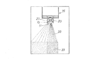
図1及び図2に示す本発明の好ましい一実施形態に係る路面散布装置10は、例えば図3に示すすように、砂利舗装30の施工面である路盤35の上に特殊開粒度アスファルト混合物31を敷き均し、敷き均した特殊開粒度アスファルト混合物31による路面32の凹凸や空隙を埋めるようにして、砂利33を散布物として散布した後に、ローラ34(図4参照)で締め固めることによって砂利舗装35を形成する工事において、図4に示すように、特殊開粒度アスファルト混合物31を敷き均すフィニッシャー36に後続して配置されて、フィニッシャー36によって敷き均された特殊開粒度アスファルト混合物31の敷均し面を路面32として、所定の散布密度で、例えば粒径が5〜13mmの天然の玉砂利からなる砂利33を、効率良く均質に散布してゆくための装置として採用されたものである。
A road
ここで、砂利舗装30は、上述のように、敷き均した特殊開粒度アスファルト混合物31による路面32の凹凸や空隙を埋めるようにして、砂利33を散布した後に、ローラ34で締め固めて得られる簡易な舗装であり、特殊開粒度アスファルト混合物31による凹凸や空隙に入り込むことで、砂利33が路面32に長期に亘って安定した状態で保持されて、維持管理や補修の手間を効果的に低減することが可能な有用な舗装構造となっている。
Here, the
そして、本実施形態の路面散布装置10は、図1及び図2に示すように、ディスク式散布機11を用いて所定の散布密度で散布物である砂利33を路面32にむらなく散布するための散布装置であって、ディスク式散布機11と、ディスク式散布機11を架装して移動可能な移動体12と、移動体12に支持されて、ディスク式散布機11と対向する前方部及びディスク式散布機11の両側の側方部を仕切って連設配置された飛散止めカバー体13と、該飛散止めカバー体13の前方カバー部13aからディスク式散布機11側に向けて、平面略V字形状に突出した状態で設けられた飛散偏向体14とを含んで構成され、飛散止めカバー体13は、ディスク式散布機11に対して進退可能に設けられており、飛散偏向体14は、平面V字形状の両側の斜辺部14a,14a間の角度θ1を調整可能に、且つ鉛直方向に対する倒れ角度θ2を調整可能に設けられている。
And the road
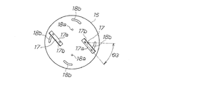
本実施形態では、ディスク式散布機11は、高速回転可能に設けられた回転ディスク15の他に、ホッパー、供給配管、回転モータ、回転駆動部、回転制御部等を備える、骨材散布用の装置として公知の散布機であり、各種の鋼材を用いて枠状に形成された支持架台16よって支持されて、移動体12の移動方向の前方に、回転軸を垂直又は略垂直に配置した状態で取り付けられている。ディスク式散布機11の回転ディスク15は、例えば直径が100〜1000mm程度の円形の鋼板からなり、この回転ディスク15には、回転軸を省略した状態で示す図5に示すように、複数の拡散羽根部材17が取り付けられている。
In this embodiment, the disk-type spreader 11 includes a hopper, a supply pipe, a rotation motor, a rotation drive unit, a rotation control unit, and the like in addition to the rotating
拡散羽根部材17は、本実施形態では、例えばL形断面を有する山形鋼の一辺部17aを回転ディスク15の上面に接合固定することで、他辺部17bを拡散羽根として立設させた状態で、4箇所に取り付け可能となっている。拡散羽根部材17は、各々、回転ディスク15の中心側に配置されたボルト締着孔18aと、回転ディスク15の外周側に配置された弧状ボルト締着穴18bとに両端部分をポルト接合することで、回転ディスク15に対して着脱可能に、且つ放射方向に対する角度θ3を調整可能に取り付けられている。
In the present embodiment, the
また、本実施形態では、ディスク式散布機11には、図1及び図2に示すように、回転ディスク15の上方を覆って上方保護板19aが設けられており、この上方保護板19aの周縁部分から下方に延設して、保護カバー19bが、回転ディスク15と上方保護板19aとの間の間隔部分を外側から覆うようにして、回転ディスク15の後部の略半円形状部分に取り付けられている。これらによって、散布物である砂利33が、回転ディスク15の上方や後方に飛散しないように規制できるようになっている。
Further, in the present embodiment, as shown in FIGS. 1 and 2, the disk type spreader 11 is provided with an upper
さらに、本実施形態では、回転ディスク15を挟んだ両側に配置されて、一対の吐出幅規制プレート20が、回転ディスク15と上方保護板19aとの間の間隔部分を側方から覆うと共に、回転ディスク15の先端部と略同じ位置まで支持架台16から前方に延設した状態で、平行に取り付けられている(図2参照)。これらの吐出幅規制プレート20の先端部の間の間隔幅によって、回転ディスク15から前方へ向けて飛散する砂利33の吐出時の飛散幅が規制され、散布物である砂利33を、飛散止めカバー体13の前方カバー部13aに向けて効率良く飛散させることができるようになっている。なお、図1、図6の側面図では、吐出幅規制プレート20を省略した状態で路面散布装置10が示されている。
Further, in the present embodiment, the pair of ejection
ディスク式散布機11が架装される移動体12としては、ローラやタイヤ等による走行部を備える、公知の各種の移動可能な重機の基台部を転用して用いることができる。移動体12には、ディスク式散布機11を支持する支持架台16や、飛散止めカバー体13の骨組構造22を支持する支持脚部21が取り付けられていて、移動体12は、ディスク式散布機11や飛散止めカバー体13を、特殊開粒度アスファルト混合物31を敷き均すフィニッシャー36に追従して、フィニッシャー36と同様の移動速度でこれの進行方向に移動させることができるようになっている。
As the moving
なお、本実施形態では、移動体12の側方に、当該移動体12と並走可能な砂利33を積載した運搬台車や、バックフォー等の砂利投入用の重機が配置されており、ディスク式散布機11のホッパーに投入用の重機を用いて砂利33を適宜投入しながら、砂利33の散布作業を行うことができるようになっている。
In this embodiment, a transport cart loaded with
飛散止めカバー体13は、支持脚部21を介して移動体12から支持される骨組構造22と、この骨組構造22に周縁部分や中間部分を接合して取り付けられる、面状部材23とからなる。面状部材23としては、好ましくはプラスチックネットを用いることができる。
The
骨組構造22は、例えば鋼製パイプ、山形鋼、帯状鋼板等を骨組部材として用いて、これらを溶接接合やボルト接合によって組み付けることにより、平面形状が略コの字形状となった立体形状に形成される。骨組構造22を構成する、略コの字形状の一対の側辺部に配置される側部横方向骨組部材24aは、鋼製パイプによって形成されており、これらの側部横方向骨組部材24aは、支持脚部21の上端部に設けられた案内支持スリーブ21aに、摺動可能に、且つボルト部材等を用いて固定可能に挿通される。これによって、骨組構造22は、移動体12に、当該移動体12及びディスク式散布機11に対して進退可能に取り付けられる。
The
また、本実施形態では、骨組構造22は、側部横方向骨組部材24aの他、略コの字形状の中間辺部に配置される中間部横方向骨組部材24b、側部横方向骨組部材24aと中間部横方向骨組部材24bとの接合角部分から下方に延設する角部縦方向骨組部材24c、側部横方向骨組部材24aと中間部横方向骨組部材24bとの接合角部分から斜め上方に延設する斜め方向骨組部材24d、案内支持スリーブ21aの先端部から上方に延設する後部縦方向骨組部材24e等を含んで構成されている。これらの骨組部材24a〜24eに周縁部分や中間部分を支持させて、飛散止めカバー体13の飛散防止用の壁面となる面状部材23を取り付けることで、前方カバー部13aと両側の側方カバー部13bとからなる平面略コの字形状の飛散止めカバー体13が、ディスク式散布機11と対向する前方部及びディスク式散布機11の両側の側方部を仕切って連設配置された状態で設けられる。
Further, in the present embodiment, the
ここで、本実施形態では、飛散止めカバー体13の飛散防止用の壁面となる面状部材23として、好ましくはプラスチックネットを用いることができる。プラスチックネットは、編むことなく、例えばポリエチレンを始めとする熱可塑性樹脂を押し出し成形することによって得られる公知の部材である。プラスチックネットは、網目の大きさが一定していると共に、目崩れによる破綻を生じることがなく、またタテ方向、ヨコ方向に安定した引っ張り強度有しており、垂直方向からの力も効率良く分散して耐衝撃性に優れると共に、比重が小さく軽量であるため取扱い性や作業性に優れるといった種々の利点を有している。このようなプラスチックネットとしては、例えば、ボリエステル系の繊維を軟質な合成樹脂で挟んで得られるビニール系素材であるターポリンを用いて形成された商品名「ターポリンクロス」や、商品名「ネトロン」(登録商標)(大日本プラスチック株式会社製)や、商品名「トリカルネット」(タキロン株式会社製)を用いることができる。
Here, in the present embodiment, a plastic net can be preferably used as the planar member 23 serving as a scattering prevention wall surface of the
また、本実施形態では、散布物である砂利33は、好ましくは粒径が5〜13mmの天然の玉砂利であることから、プラスチックネットによる面状部材23は、網目ピッチが例えば2〜5mm程度のものを用いることが好ましい。
Moreover, in this embodiment, since the
飛散止めカバー体13を構成する面状部材23としてプラスチックネットを用いることにより、その適度な弾性によって、ディスク式散布機11から飛散する砂利33を当該プラスチックネットに衝突させて落下させることで、砂利33を所定の散布密度で効率良く均質に散布してゆく機能を、さらに効果的に発揮させることが可能になる。
By using a plastic net as the planar member 23 constituting the
さらに、本実施形態では、プラスチックネットによる面状部材23を外側から覆うようにして、例えばブルーシート等からなる飛散防止用のシート部材(図示せず。)を、飛散止めカバー体13に取り付けておくこともできる。プラスチックネットによる面状部材23を外側から覆ってシート部材を取り付けておくことにより、プラスチックネットの網目を通過する細かな砂利33の粒子が、飛散止めカバー体13の外部に飛散するのを効果的に防止することが可能になる。
Further, in the present embodiment, a sheet member (not shown) for preventing scattering, such as a blue sheet, is attached to the scattering
そして、本実施形態では、飛散止めカバー体13の前方カバー部13aからディスク式散布機11側に向けて、飛散偏向体14が、平面略V字形状に突出した状態で、いわゆるディフレクターとして設けられている。飛散偏向体14は、飛散止めカバー体13の前方カバー部13aから支持される偏向体骨組構造25と、この偏向体骨組構造25に周縁部分や中間部分を接合して取り付けられる、偏向体面状部材26とからなる。偏向体面状部材26としては、飛散止めカバー体13の面状部材23と同様に、好ましくは網目ピッチが例えば2〜5mm程度のプラスチックネットを用いることができる。
In the present embodiment, the scattering
飛散偏向体14を構成する偏向体面状部材26としてプラスチックネットを用いることにより、その適度な弾性によって、当該プラスチックネットに砂利33を衝突させ、回転方向後方側に偏向させてまとまった状態から分散させることで、散布密度のぱらつきや偏りを抑制する機能を、さらに効果的に発揮させることが可能になる。
By using a plastic net as the
偏向体骨組構造25は、例えば鋼製パイプ、山形鋼、帯状鋼板等を骨組部材として用いて、これらを溶接接合やボルト接合によって組み付けることにより、平面形状が略V字形状となった立体形状に形成される。偏向体骨組構造25は、前方カバー部13aの骨組構造22によって支持されて、前方カバー部13aからディスク式散布機11に向けて内側に突出した状態で設けられる。この偏向体骨組構造25に周縁部分や中間部分を支持させて、飛散偏向体14の偏向用の壁面となる偏向体面状部材26を取り付けることで、両側の一対の斜辺部14a,14aからなる平面略V字形状の飛散偏向体14が、ディスク式散布機11に向けて突出した状態で設けられる。また、偏向体骨組構造25は、公知の各種の角度調整機構を備えることで、略V字形状の開き角度を調整可能に、且つ鉛直方向に対する上下方向の角度を調整可能に形成されている。これによって、飛散偏向体14は、両側の斜辺部14a,14a間の角度θ1を調整することができるようになっていると共に、鉛直方向に対する倒れ角度θ2を調整することができるようになっている。
The
本実施形態では、図2及び図6に示すように、飛散止めカバー体13の両側の側方カバー部13bの間の間隔幅によって画定される、路面散布装置10による施工幅Bや、散布物の種類、散布密度等に応じて、ディスク式散布機11と前方カバー部13aとの間の間隔L1、飛散偏向体14の両側の斜辺部14a,14a間の角度θ1、飛散偏向体14の鉛直方向に対する倒れ角度θ2等を適宜調整して、散布物を散布するようになっている。
In this embodiment, as shown in FIGS. 2 and 6, the construction width B by the road
すなわち、本実施形態では、例えば、路面散布装置10による施工幅Bは2〜4mとなっており、散布物は、粒径が5〜13mmの天然の玉砂利からなる砂利33であり、また散布密度を10〜25kg/m2と設定した場合には、ディスク式散布機11と前方カバー部13aとの間の間隔L1は、飛散止めカバー体13の端部まで効率良く砂利33が広がるように、例えば300〜900mm程度(実際の施工時680mm)とすることが好ましい。ディスク式散布機11と前方カバー部13aとの間の間隔L1の調整は、上述のように、飛散止めカバー体13の骨組構造22の側部横方向骨組部材24aを、支持脚部21の案内支持スリーブ21aに対して摺動させて、骨組構造22をディスク式散布機11に対して進退させることで、容易に行うことができる。
That is, in this embodiment, for example, the construction width B by the road
また、本実施形態では、飛散偏向体14の両側の斜辺部14a,14a間の角度θ1は、飛散止めカバー体13の端部まで効率良く砂利33が広がるように、例えば80〜150°程度(実際の施工時、上下共に94°)とすることが好ましい。飛散偏向体14の鉛直方向に対する倒れ角度θ2は、飛散止めカバー体13の中心部から端部まで均一に砂利33が散布されるように、例えば0〜30°程度(実際の施工時13°)とすることが好ましい。
In the present embodiment, the angle θ1 between the
なお、本実施形態では、飛散偏向体14は、これの中心がディスク式散布機11の回転軸の中心よりも、図2において上方(回転方向前方側)に例えば30〜60mm程度(実際の施工時42.5mm)のずれ幅L2でずれて配置されるようにセットされている。これによって、ディスク式散布機11の回転方向前方側への砂利33の広がりを抑制することが可能になる。また、飛散偏向体14のプラスチックネットによる偏向体面状部材26の高さ方向の長さL3は、例えば475〜675mm程度(実際の施工時575mm)となっている。これによって、中心部分への砂利33の散布量を調整することが可能になる。
In the present embodiment, the scattering
そして、上述の構成を備える本実施形態の路面散布装置10によれば、散布物が比重の比較的大きな砂利31であっても、ディスク式散布機11によって、所定の散布密度で効率良く均質に、特殊開粒度アスファルト混合物31の敷均し面による路面32に砂利33を散布してゆくことが可能になる。
And according to the road
すなわち、本実施形態の路面散布装置10は、ディスク式散布機11と対向する前方部及びディスク式散布機11の両側の側方部を仕切って連設配置された飛散止めカバー体13と、飛散止めカバー体13の前方カバー部13aからディスク式散布機11側に向けて平面略V字形状に突出して設けられた飛散偏向体14とを含んで構成されているので、図8に示すように、散布物である砂利33が、例えばディスク式散布機11の回転ディスク15の回転方向後方側ではまとまった状態で飛ばされ、回転方向前方側では広がった状態で飛ばされる場合であっても、図7に示すように、まとまった状態で飛ばされた回転方向後方側の砂利33を、飛散偏向体14の好ましくはプラスチックネットによる偏向体面状部材26に衝突させることで、衝突させた砂利33を、さらに回転方向後方側に偏向させてまとまった状態から分散させることで、散布密度のぱらつきや偏りを効果的に抑制して、砂利33を路面32にむらなく均質に散布してゆくことが可能になる。
That is, the road
なお、本発明は上記実施形態に限定されることなく種々の変更が可能である。例えば、飛散偏向体の偏向体面状部材や飛散止めカバー体の面状部材は、プラスチックネットによって構成されるものである必要は必ずしも無く、その他の板状部材やシート状部材であっても良い。また、本発明の路面散布装置によって散布される散布物は、粒径が5〜13mmの天然の玉砂利である必要は必ずしもなく、その他の骨材や砕石や砂利等の比重が比較的高い散布物の他、凍結抑制剤やゴムチップ等の比重が比較的小さい散布物であっても良い。 The present invention is not limited to the above-described embodiment, and various modifications can be made. For example, the deflecting body planar member of the scattering deflector and the planar member of the anti-scattering cover body do not necessarily need to be constituted by a plastic net, and may be other plate-like members or sheet-like members. In addition, the sprayed material sprayed by the road surface spraying device of the present invention is not necessarily natural gravel having a particle size of 5 to 13 mm, and other sprayed material having a relatively high specific gravity such as aggregate, crushed stone, or gravel. In addition, a sprinkle having a relatively small specific gravity, such as a freezing inhibitor or a rubber chip, may be used.
10 路面散布装置
11 ディスク式散布機
12 移動体
13 飛散止めカバー体
13a 前方カバー部
13b 側方カバー部
14 飛散偏向体
14a 斜辺部
15 回転ディスク
16 支持架台
17 拡散羽根部材
20 吐出幅規制プレート
21 支持脚部
21a 案内支持スリーブ
22 骨組構造
23 面状部材
25 偏向体骨組構造
26 偏向体面状部材
30 砂利舗装
31 特殊開粒度アスファルト混合物
32 路面
33 砂利(散布物)
DESCRIPTION OF
Claims (5)
前記ディスク式散布機と、前記ディスク式散布機を架装して移動可能な移動体と、該移動体に支持されて、前記ディスク式散布機と対向する前方部及び前記ディスク式散布機の両側の側方部を仕切って連設配置された飛散止めカバー体と、該飛散止めカバー体の前方カバー部から前記ディスク式散布機側に向けて、平面略V字形状に突出した状態で設けられた飛散偏向体とを含んで構成され、
前記飛散止めカバー体は、前記ディスク式散布機に対して進退可能に設けられており、前記飛散偏向体は、前記平面V字形状の両側の斜辺部間の角度を調整可能に、且つ鉛直方向に対する倒れ角度を調整可能に設けられている路面散布装置。 A road surface spraying device for spraying scattered material evenly on a road surface with a predetermined spraying density using a disk-type spreader,
The disk-type spreader, a movable body that is movable by mounting the disk-type spreader, a front portion that is supported by the movable body and faces the disk-type spreader, and both sides of the disk-type spreader The anti-scatter cover body that is continuously arranged by partitioning the side portions of the anti-scattering cover body, and is provided in a state of projecting in a substantially V-shaped plane from the front cover portion of the anti-scatter cover body toward the disk-type spreader side. And a scattering deflector,
The anti-scatter cover body is provided so as to be able to advance and retreat with respect to the disk-type spreader, and the anti-scattering body is capable of adjusting the angle between the hypotenuses on both sides of the flat V-shape and in the vertical direction. Road surface spraying device that can adjust the tilt angle with respect to.
Priority Applications (1)
| Application Number | Priority Date | Filing Date | Title |
|---|---|---|---|
| JP2011122615A JP5687957B2 (en) | 2011-05-31 | 2011-05-31 | Road spraying device |
Applications Claiming Priority (1)
| Application Number | Priority Date | Filing Date | Title |
|---|---|---|---|
| JP2011122615A JP5687957B2 (en) | 2011-05-31 | 2011-05-31 | Road spraying device |
Publications (2)
| Publication Number | Publication Date |
|---|---|
| JP2012251305A true JP2012251305A (en) | 2012-12-20 |
| JP5687957B2 JP5687957B2 (en) | 2015-03-25 |
Family
ID=47524362
Family Applications (1)
| Application Number | Title | Priority Date | Filing Date |
|---|---|---|---|
| JP2011122615A Active JP5687957B2 (en) | 2011-05-31 | 2011-05-31 | Road spraying device |
Country Status (1)
| Country | Link |
|---|---|
| JP (1) | JP5687957B2 (en) |
Cited By (3)
| Publication number | Priority date | Publication date | Assignee | Title |
|---|---|---|---|---|
| JP2015224535A (en) * | 2014-05-30 | 2015-12-14 | 株式会社東洋スタビ | Self-traveling type powder spraying device for spraying powder for ground improvement |
| JP2017166305A (en) * | 2016-03-09 | 2017-09-21 | 株式会社タイショー | Spray device |
| CN116556148A (en) * | 2023-07-04 | 2023-08-08 | 山西一建集团有限公司 | Auxiliary device for paving block-shaped heat insulation material |
Citations (7)
| Publication number | Priority date | Publication date | Assignee | Title |
|---|---|---|---|---|
| JPS4810651Y1 (en) * | 1968-10-02 | 1973-03-22 | ||
| JPS4864222U (en) * | 1971-11-22 | 1973-08-15 | ||
| JPS61202510U (en) * | 1985-06-07 | 1986-12-19 | ||
| JP3021394U (en) * | 1995-05-25 | 1996-02-20 | 株式会社石田土建 | Anti-skid material sprayer for frozen road surfaces |
| JPH08218312A (en) * | 1995-02-10 | 1996-08-27 | Kajima Doro Kk | Aggregate scattering apparatus |
| US20030155453A1 (en) * | 2002-02-06 | 2003-08-21 | Scott Kinkead | Broadcast spreading top dresser |
| JP2011064031A (en) * | 2009-09-18 | 2011-03-31 | Kajima Corp | Cooling device of roof deck |
-
2011
- 2011-05-31 JP JP2011122615A patent/JP5687957B2/en active Active
Patent Citations (7)
| Publication number | Priority date | Publication date | Assignee | Title |
|---|---|---|---|---|
| JPS4810651Y1 (en) * | 1968-10-02 | 1973-03-22 | ||
| JPS4864222U (en) * | 1971-11-22 | 1973-08-15 | ||
| JPS61202510U (en) * | 1985-06-07 | 1986-12-19 | ||
| JPH08218312A (en) * | 1995-02-10 | 1996-08-27 | Kajima Doro Kk | Aggregate scattering apparatus |
| JP3021394U (en) * | 1995-05-25 | 1996-02-20 | 株式会社石田土建 | Anti-skid material sprayer for frozen road surfaces |
| US20030155453A1 (en) * | 2002-02-06 | 2003-08-21 | Scott Kinkead | Broadcast spreading top dresser |
| JP2011064031A (en) * | 2009-09-18 | 2011-03-31 | Kajima Corp | Cooling device of roof deck |
Cited By (4)
| Publication number | Priority date | Publication date | Assignee | Title |
|---|---|---|---|---|
| JP2015224535A (en) * | 2014-05-30 | 2015-12-14 | 株式会社東洋スタビ | Self-traveling type powder spraying device for spraying powder for ground improvement |
| JP2017166305A (en) * | 2016-03-09 | 2017-09-21 | 株式会社タイショー | Spray device |
| CN116556148A (en) * | 2023-07-04 | 2023-08-08 | 山西一建集团有限公司 | Auxiliary device for paving block-shaped heat insulation material |
| CN116556148B (en) * | 2023-07-04 | 2023-09-08 | 山西一建集团有限公司 | Auxiliary device for paving block-shaped heat insulation material |
Also Published As
| Publication number | Publication date |
|---|---|
| JP5687957B2 (en) | 2015-03-25 |
Similar Documents
| Publication | Publication Date | Title |
|---|---|---|
| JP5687957B2 (en) | Road spraying device | |
| US7448825B2 (en) | Method for continuous on-site recycling of an asphalt mixture layer of a pavement and a motor-driven vehicle system therefor | |
| US6932286B2 (en) | Combination drop and broadcast spreader | |
| US8267482B1 (en) | Foam configured to suppress dust on a surface to be worked | |
| JPH05508458A (en) | Paving material distribution system | |
| US20100202832A1 (en) | Civil Engineering Machine For Spreading Material For Spreading On Soils Or Base Materials | |
| US6336769B1 (en) | Screeding apparatus and components therefor | |
| JP3713315B2 (en) | Vibrating sieve machine and lump crushing plant vehicle equipped with the vibrating sieve machine | |
| US20160145814A1 (en) | Dispensing device for filler material | |
| JP2013092042A (en) | Spray device, in particular for spraying of sand for spraying | |
| US6319545B1 (en) | Method for constructing a resilient surface | |
| JP4411534B2 (en) | Joint spreader | |
| KR101743880B1 (en) | Sand spreader for green | |
| JP5116648B2 (en) | Concrete distribution equipment | |
| ES2610972B2 (en) | Dosing-spreading hopper for tamping machines | |
| EP1300517B1 (en) | Apparatus for incorporating granular material in an asphalt layer | |
| JP3756557B2 (en) | Lump crushing plant car | |
| JP6731462B2 (en) | Asphalt mixture leveling device and asphalt mixture leveling member | |
| CN211922204U (en) | Road shoulder ridging wheel type paver | |
| JPH09136668A (en) | Plant vehicle to be loaded with equipment on load carrying platform with gate | |
| JP6957049B2 (en) | Recovery casting sand cooling device | |
| JP4829642B2 (en) | Slope construction equipment | |
| JPH09262495A (en) | Crushing plant vehicle | |
| JP4237358B2 (en) | Aggregate spreader | |
| CA2366749A1 (en) | Improved screeding apparatus and components therefor |
Legal Events
| Date | Code | Title | Description |
|---|---|---|---|
| A621 | Written request for application examination |
Free format text: JAPANESE INTERMEDIATE CODE: A621 Effective date: 20140327 |
|
| A977 | Report on retrieval |
Free format text: JAPANESE INTERMEDIATE CODE: A971007 Effective date: 20141211 |
|
| A131 | Notification of reasons for refusal |
Free format text: JAPANESE INTERMEDIATE CODE: A131 Effective date: 20141216 |
|
| A521 | Request for written amendment filed |
Free format text: JAPANESE INTERMEDIATE CODE: A523 Effective date: 20141217 |
|
| TRDD | Decision of grant or rejection written | ||
| A01 | Written decision to grant a patent or to grant a registration (utility model) |
Free format text: JAPANESE INTERMEDIATE CODE: A01 Effective date: 20150113 |
|
| A61 | First payment of annual fees (during grant procedure) |
Free format text: JAPANESE INTERMEDIATE CODE: A61 Effective date: 20150123 |
|
| R150 | Certificate of patent or registration of utility model |
Ref document number: 5687957 Country of ref document: JP Free format text: JAPANESE INTERMEDIATE CODE: R150 |
|
| R250 | Receipt of annual fees |
Free format text: JAPANESE INTERMEDIATE CODE: R250 |
|
| S531 | Written request for registration of change of domicile |
Free format text: JAPANESE INTERMEDIATE CODE: R313531 |
|
| R350 | Written notification of registration of transfer |
Free format text: JAPANESE INTERMEDIATE CODE: R350 |
|
| R250 | Receipt of annual fees |
Free format text: JAPANESE INTERMEDIATE CODE: R250 |
|
| R250 | Receipt of annual fees |
Free format text: JAPANESE INTERMEDIATE CODE: R250 |
|
| R250 | Receipt of annual fees |
Free format text: JAPANESE INTERMEDIATE CODE: R250 |
|
| R250 | Receipt of annual fees |
Free format text: JAPANESE INTERMEDIATE CODE: R250 |
|
| R250 | Receipt of annual fees |
Free format text: JAPANESE INTERMEDIATE CODE: R250 |
|
| R250 | Receipt of annual fees |
Free format text: JAPANESE INTERMEDIATE CODE: R250 |