JP2012250039A - Electrosurgical apparatus with tissue site sensing and feedback control - Google Patents
Electrosurgical apparatus with tissue site sensing and feedback control Download PDFInfo
- Publication number
- JP2012250039A JP2012250039A JP2012123174A JP2012123174A JP2012250039A JP 2012250039 A JP2012250039 A JP 2012250039A JP 2012123174 A JP2012123174 A JP 2012123174A JP 2012123174 A JP2012123174 A JP 2012123174A JP 2012250039 A JP2012250039 A JP 2012250039A
- Authority
- JP
- Japan
- Prior art keywords
- electrosurgical
- sensor
- lead
- tissue
- coupled
- Prior art date
- Legal status (The legal status is an assumption and is not a legal conclusion. Google has not performed a legal analysis and makes no representation as to the accuracy of the status listed.)
- Granted
Links
Images


Classifications
-
- A—HUMAN NECESSITIES
- A61—MEDICAL OR VETERINARY SCIENCE; HYGIENE
- A61B—DIAGNOSIS; SURGERY; IDENTIFICATION
- A61B18/00—Surgical instruments, devices or methods for transferring non-mechanical forms of energy to or from the body
- A61B18/04—Surgical instruments, devices or methods for transferring non-mechanical forms of energy to or from the body by heating
- A61B18/12—Surgical instruments, devices or methods for transferring non-mechanical forms of energy to or from the body by heating by passing a current through the tissue to be heated, e.g. high-frequency current
- A61B18/1206—Generators therefor
-
- A—HUMAN NECESSITIES
- A61—MEDICAL OR VETERINARY SCIENCE; HYGIENE
- A61B—DIAGNOSIS; SURGERY; IDENTIFICATION
- A61B18/00—Surgical instruments, devices or methods for transferring non-mechanical forms of energy to or from the body
- A61B18/04—Surgical instruments, devices or methods for transferring non-mechanical forms of energy to or from the body by heating
- A61B18/12—Surgical instruments, devices or methods for transferring non-mechanical forms of energy to or from the body by heating by passing a current through the tissue to be heated, e.g. high-frequency current
- A61B18/14—Probes or electrodes therefor
- A61B18/1442—Probes having pivoting end effectors, e.g. forceps
- A61B18/1445—Probes having pivoting end effectors, e.g. forceps at the distal end of a shaft, e.g. forceps or scissors at the end of a rigid rod
-
- A—HUMAN NECESSITIES
- A61—MEDICAL OR VETERINARY SCIENCE; HYGIENE
- A61B—DIAGNOSIS; SURGERY; IDENTIFICATION
- A61B17/00—Surgical instruments, devices or methods, e.g. tourniquets
- A61B2017/00017—Electrical control of surgical instruments
- A61B2017/00022—Sensing or detecting at the treatment site
- A61B2017/00057—Light
-
- A—HUMAN NECESSITIES
- A61—MEDICAL OR VETERINARY SCIENCE; HYGIENE
- A61B—DIAGNOSIS; SURGERY; IDENTIFICATION
- A61B18/00—Surgical instruments, devices or methods for transferring non-mechanical forms of energy to or from the body
- A61B2018/00053—Mechanical features of the instrument of device
- A61B2018/00172—Connectors and adapters therefor
- A61B2018/00178—Electrical connectors
-
- A—HUMAN NECESSITIES
- A61—MEDICAL OR VETERINARY SCIENCE; HYGIENE
- A61B—DIAGNOSIS; SURGERY; IDENTIFICATION
- A61B18/00—Surgical instruments, devices or methods for transferring non-mechanical forms of energy to or from the body
- A61B2018/00571—Surgical instruments, devices or methods for transferring non-mechanical forms of energy to or from the body for achieving a particular surgical effect
- A61B2018/0063—Sealing
-
- A—HUMAN NECESSITIES
- A61—MEDICAL OR VETERINARY SCIENCE; HYGIENE
- A61B—DIAGNOSIS; SURGERY; IDENTIFICATION
- A61B18/00—Surgical instruments, devices or methods for transferring non-mechanical forms of energy to or from the body
- A61B2018/00636—Sensing and controlling the application of energy
- A61B2018/00642—Sensing and controlling the application of energy with feedback, i.e. closed loop control
-
- A—HUMAN NECESSITIES
- A61—MEDICAL OR VETERINARY SCIENCE; HYGIENE
- A61B—DIAGNOSIS; SURGERY; IDENTIFICATION
- A61B18/00—Surgical instruments, devices or methods for transferring non-mechanical forms of energy to or from the body
- A61B2018/00636—Sensing and controlling the application of energy
- A61B2018/00773—Sensed parameters
- A61B2018/00875—Resistance or impedance
-
- H—ELECTRICITY
- H01—ELECTRIC ELEMENTS
- H01B—CABLES; CONDUCTORS; INSULATORS; SELECTION OF MATERIALS FOR THEIR CONDUCTIVE, INSULATING OR DIELECTRIC PROPERTIES
- H01B7/00—Insulated conductors or cables characterised by their form
- H01B7/04—Flexible cables, conductors, or cords, e.g. trailing cables
- H01B7/048—Flexible cables, conductors, or cords, e.g. trailing cables for implantation into a human or animal body, e.g. pacemaker leads
Abstract
Description
(発明の詳細な説明)
(発明の分野)
(技術分野)
本開示は、電気外科処置を行う電気外科システムおよび方法に関する。より具体的には、本開示は、治療部位からのセンサー信号フィードバックを用いて、治療部位における組織およびエネルギーパラメータ情報を送信および監視するシステムおよび方法に関する。本開示は、組織およびエネルギーパラメータに基づいて、閉ループの態様で電気外科無線周波数エネルギーを送信、監視および制御するシステムおよび方法にも関する。
(Detailed description of the invention)
(Field of Invention)
(Technical field)
The present disclosure relates to electrosurgical systems and methods for performing electrosurgical procedures. More specifically, the present disclosure relates to systems and methods for transmitting and monitoring tissue and energy parameter information at a treatment site using sensor signal feedback from the treatment site. The present disclosure also relates to systems and methods for transmitting, monitoring and controlling electrosurgical radio frequency energy in a closed loop manner based on tissue and energy parameters.
(発明の背景)
(関連技術の背景)
電気外科は、組織を切断、切除または凝固させるために、高無線周波数電流を外科手術部位に印加することを含む。双極電気外科において、ハンドヘルドの器具の電極のうちの一方は、活性電極として機能し、他方は、帰還電極として機能する。帰還電極は、電気回路が2つの電極(例えば、電気外科鉗子)間に形成されるように、活性電極に近接して設置される。このようにして、印加された電流は、電極間に位置決めされた身体組織に限定される。電極が互いから十分に分離された場合、電気回路は開放されており、したがって、分離された電極のうちの一方との身体組織の予期せぬ接触が電流の流れを妨げる。
(Background of the Invention)
(Background of related technology)
Electrosurgery involves applying a high radio frequency current to a surgical site to cut, ablate or coagulate tissue. In bipolar electrosurgery, one of the electrodes of the handheld instrument functions as the active electrode and the other functions as the return electrode. The return electrode is placed in close proximity to the active electrode so that an electrical circuit is formed between the two electrodes (eg, electrosurgical forceps). In this way, the applied current is limited to the body tissue positioned between the electrodes. When the electrodes are sufficiently separated from each other, the electrical circuit is open, and thus unexpected contact of body tissue with one of the separated electrodes prevents current flow.
双極電気外科は、概して、鉗子の使用を含む。鉗子は、プライヤー様の器具であり、脈管または組織を把持、クランプ締めおよび圧縮するために、器具のジョー間の機械的作用に頼る。いわゆる、「開放鉗子」は、開放外科手術処置において一般的に用いられるが、「内視鏡鉗子」または「腹腔鏡鉗子」は、名前が示す通り、より侵襲性が低い内視鏡外科手術処置に対して用いられる。(開放または内視鏡)電気外科鉗子は、クランプ締めされた組織に止血をもたらすために、機械的クランプ締め作用および電気エネルギーを使用する。鉗子は、電気外科エネルギーをクランプ締めされた組織に適用する電気外科伝導性表面を含む。伝導性プレートを通して、組織に適用される電気外科エネルギーの強度、周波数および持続時間を制御することによって、外科医は、組織を凝固、焼灼および/または密閉し得る。 Bipolar electrosurgery generally involves the use of forceps. Forceps are pliers-like instruments that rely on mechanical action between the jaws of the instrument to grasp, clamp and compress vessels or tissue. So-called “open forceps” are commonly used in open surgical procedures, but “endoscopic forceps” or “laparoscopic forceps” are less invasive endoscopic surgical procedures, as the name implies. Used for. (Open or Endoscope) Electrosurgical forceps use mechanical clamping action and electrical energy to provide hemostasis to the clamped tissue. The forceps includes an electrosurgical conductive surface that applies electrosurgical energy to the clamped tissue. By controlling the intensity, frequency and duration of electrosurgical energy applied to the tissue through the conductive plate, the surgeon can coagulate, cauterize and / or seal the tissue.
組織または脈管密閉は、組織中のコラーゲン、エラスチンおよび基質を液化させる処理であり、その結果、コラーゲン、エラスチンおよび基質は、対向する組織構造間の境界が十分に減少した融解物に再形成される。焼灼は、組織を破壊するために、熱の使用を含み、凝固は、組織を乾燥させる処理であり、組織細胞は、破裂し、乾く。 Tissue or vascular sealing is the process of liquefying collagen, elastin and matrix in the tissue so that the collagen, elastin and matrix are reformed into a melt with sufficiently reduced boundaries between opposing tissue structures. The Cauterization involves the use of heat to destroy tissue, coagulation is the process of drying the tissue, and tissue cells rupture and dry.
組織密閉処置は、効果的な密閉を作成するために、単に組織を焼灼または凝固させる以上のことを含む。処置は、さまざまな要因の正確な制御を含む。例えば、脈管または組織中の適切な密閉に影響を与えるために、組織に適用される圧力と、電極間のギャップ距離(つまり対向するジョー部材または対向する密閉表面間の距離)との2つの支配的な機械的パラメータが誤差なく制御されなければならないことが決定される。加えて、電気外科エネルギーは、効果的な脈管密閉の作成を確実にするために、制御された条件下で組織に適用されなければならない。 Tissue sealing procedures involve more than simply cauterizing or coagulating tissue to create an effective seal. Treatment involves precise control of various factors. For example, to affect proper sealing in a vessel or tissue, the pressure applied to the tissue and the gap distance between the electrodes (ie the distance between the opposing jaw members or opposing sealing surfaces) It is determined that the dominant mechanical parameters must be controlled without error. In addition, electrosurgical energy must be applied to the tissue under controlled conditions to ensure the creation of an effective vascular seal.
治療部位への電気外科エネルギーの送信(つまり、電気外科発電機から器具まで)は、電気外科ケーブルを介して実現される。送信中、電界がケーブルを通して生成され、漂遊電気外科RFエネルギーは、典型的には、ケーブル経路に沿って放出される。ケーブル経路は、治療エネルギーを減少させる傾向があり、RFノイズを生成する。さらに、電界は、患者監視機器のような、外科手術範囲内の他の電子機器の動作に干渉し得る。 Transmission of electrosurgical energy to the treatment site (ie, from the electrosurgical generator to the instrument) is accomplished via an electrosurgical cable. During transmission, an electric field is generated through the cable, and stray electrosurgical RF energy is typically emitted along the cable path. The cable path tends to reduce therapeutic energy and generates RF noise. In addition, the electric field can interfere with the operation of other electronic devices within the surgical scope, such as patient monitoring devices.
(発明の概要)
本開示は、電気外科無線周波数(「RF」)エネルギーの送信に関する。供給および帰還送信リードの間に結合する近接電場を有している電気外科ケーブルが開示される。結合することは、外科手術中に搬送されるRFエネルギーの適用を最大化し、供給および帰還リードによって放射される漂遊RFエネルギーを最小化する。近接電場結合は、場消去を介して電場を有意に減少させることによって、患者及び外科医の安全性を増加させる。結合は、供給および帰還リードの3次元幾何学的配向を介して、低損失誘導/静電容量(「LC」)送信媒体を提供する。幾何学的配向は、LC反応部品に影響し、漂遊RF放射によって生じる制御されていない静電容量リアクタンスを減少させる。特に、静電容量リアクタンスは、アンテナ効果(例えば、漂遊RFエネルギーの急速な放電)によって、半波長より短い送信媒体に対して生じる。そのため、漂遊RFエネルギーの損失は、エネルギー供給源(例えば、電気外科エネルギー)に対する容量性装荷も減少させる所定のレベルまで含まれる。
(Summary of Invention)
The present disclosure relates to the transmission of electrosurgical radio frequency (“RF”) energy. An electrosurgical cable having a near electric field coupled between the supply and return transmission leads is disclosed. Coupling maximizes the application of RF energy delivered during the surgical procedure and minimizes stray RF energy radiated by the supply and return leads. Near field coupling increases patient and surgeon safety by significantly reducing the field through field cancellation. Coupling provides a low loss inductive / capacitance (“LC”) transmission medium through the three-dimensional geometric orientation of the supply and return leads. The geometric orientation affects the LC reactive components and reduces the uncontrolled capacitive reactance caused by stray RF radiation. In particular, capacitive reactance occurs for transmission media shorter than half a wavelength due to antenna effects (eg, rapid discharge of stray RF energy). As such, the loss of stray RF energy is included to a predetermined level that also reduces capacitive loading on the energy source (eg, electrosurgical energy).
本開示は、発電機および電気外科器具を含む電気外科システムを提供する。発電機は、少なくとも1つの活性リードに結合されている少なくとも1つの活性出力端子と、少なくとも1つの帰還リードに結合されている少なくとも1つの帰還出力端子とを有している。電気外科器具は、少なくとも1つの活性リードおよび少なくとも1つの帰還リードに結合されている。電気外科器具は、少なくとも1つのセンサーを含む。少なくとも1つのセンサーは、組織接触部分に配置され、少なくとも1つのセンサー線を通して発電機に結合されている。システムは、誘電性コアを含む電気外科ケーブルも含む。少なくとも1つのセンサー線は、誘電性コア内に配置され、少なくとも1つの活性リードおよび少なくとも1つの帰還リードの各々の少なくとも一部が二重螺旋状に誘電性コアの周りに巻きつけられることにより、少なくとも1つの活性リードおよび少なくとも1つの帰還リードによって生成された電場を最小化する。 The present disclosure provides an electrosurgical system that includes a generator and an electrosurgical instrument. The generator has at least one active output terminal coupled to at least one active lead and at least one feedback output terminal coupled to at least one feedback lead. The electrosurgical instrument is coupled to at least one active lead and at least one return lead. The electrosurgical instrument includes at least one sensor. At least one sensor is disposed at the tissue contacting portion and is coupled to the generator through at least one sensor line. The system also includes an electrosurgical cable that includes a dielectric core. At least one sensor line is disposed within the dielectric core, and at least a portion of each of the at least one active lead and the at least one feedback lead is wound around the dielectric core in a double helix, Minimize the electric field generated by at least one active lead and at least one feedback lead.
実施形態において、本開示は、少なくとも1つの活性リードに結合されている少なくとも1つの活性出力端子と、少なくとも1つの帰還リードに結合されている少なくとも1つの帰還出力端子とを有している発電機を含む電気外科システムも提供する。システムは、2つのジョー部材を有している電気外科鉗子を含む。2つのジョー部材の少なくとも一方は、他方に対して一定の距離を置かれた関係の第一の位置から、ジョー部材が協働してその間の組織を把持する少なくとも1つの後続する位置まで可動である。ジョー部材の各々は、導電性密閉表面を含む。1つの導電性密閉表面は、少なくとも1つの活性リードに結合されており、別の導電性密閉表面は、少なくとも1つの帰還リードに結合されている。鉗子も少なくとも1つのセンサーを含む。少なくとも1つのセンサーは、ジョー部材の少なくとも一方の中に配置され、少なくとも1つのセンサー線を通して発電機に結合されている。システムは、誘電性コアを含む電気外科ケーブルをさらに含む。少なくとも1つのセンサー線は、誘電性コア内に配置され、少なくとも1つの活性リードおよび少なくとも1つの帰還リードの各々の少なくとも一部が二重螺旋状に誘電性コアの周りに巻きつけられることにより、少なくとも1つの活性リードおよび少なくとも1つの帰還リードによって生成された電場を最小化する。 In an embodiment, the present disclosure provides a generator having at least one active output terminal coupled to at least one active lead and at least one feedback output terminal coupled to at least one feedback lead. An electrosurgical system is also provided. The system includes an electrosurgical forceps having two jaw members. At least one of the two jaw members is movable from a first position in a fixed distance relative to the other to at least one subsequent position where the jaw members cooperate to grasp tissue therebetween. is there. Each of the jaw members includes a conductive sealing surface. One conductive sealing surface is coupled to at least one active lead, and another conductive sealing surface is coupled to at least one return lead. The forceps also includes at least one sensor. At least one sensor is disposed in at least one of the jaw members and is coupled to the generator through at least one sensor line. The system further includes an electrosurgical cable that includes a dielectric core. At least one sensor line is disposed within the dielectric core, and at least a portion of each of the at least one active lead and the at least one feedback lead is wound around the dielectric core in a double helix, Minimize the electric field generated by at least one active lead and at least one feedback lead.
さらなる実施形態において、本開示は、少なくとも1つの活性リードに結合されている少なくとも1つの活性出力端子と、少なくとも1つの帰還リードに結合されている少なくとも1つの帰還出力端子とを有している発電機を含む電気外科システムを提供する。システムは、2つのジョー部材を有している電気外科鉗子も含む。2つのジョー部材の少なくとも一方は、他方に対して一定の距離を置かれた関係の第一の位置から、ジョー部材が協働してその間の組織を把持する少なくとも1つの後続する位置まで可動である。ジョー部材の各々は、導電性密閉表面を含む。1つの導電性密閉表面は、少なくとも1つの活性リードに結合されており、別の導電性密閉表面は、少なくとも1つの帰還リードに結合されている。鉗子も少なくとも1つの電気センサーおよび少なくとも1つの光学センサーを含む。少なくとも1つの電気センサーは、ジョー部材の少なくとも一方の中に配置され、導電性密閉表面の少なくとも一方と、発電機とに少なくとも1つの電気センサー線を通して結合されている。少なくとも1つの光学センサーは、ジョー部材の少なくとも一方の中に配置され、少なくとも1つの光学送信線を通して発電機に結合されている。システムは、誘電性コアを含む電気ケーブルをさらに含む。少なくとも1つのセンサー線は、誘電性コア内に配置され、少なくとも1つの活性リードおよび少なくとも1つの帰還リードの各々の少なくとも一部が二重螺旋状に誘電性コアの周りに巻きつけられることにより、少なくとも1つの活性リードおよび少なくとも1つの帰還リードによって生成された電場を最小化する。 In a further embodiment, the present disclosure provides for power generation having at least one active output terminal coupled to at least one active lead and at least one feedback output terminal coupled to at least one feedback lead. An electrosurgical system including a machine is provided. The system also includes an electrosurgical forceps having two jaw members. At least one of the two jaw members is movable from a first position in a fixed distance relative to the other to at least one subsequent position where the jaw members cooperate to grasp tissue therebetween. is there. Each of the jaw members includes a conductive sealing surface. One conductive sealing surface is coupled to at least one active lead, and another conductive sealing surface is coupled to at least one return lead. The forceps also includes at least one electrical sensor and at least one optical sensor. At least one electrical sensor is disposed in at least one of the jaw members and is coupled to at least one of the conductive sealing surface and the generator through at least one electrical sensor line. At least one optical sensor is disposed in at least one of the jaw members and is coupled to the generator through at least one optical transmission line. The system further includes an electrical cable that includes a dielectric core. At least one sensor line is disposed within the dielectric core, and at least a portion of each of the at least one active lead and the at least one feedback lead is wound around the dielectric core in a double helix, Minimize the electric field generated by at least one active lead and at least one feedback lead.
本開示の一局面において、電気外科システムが開示される。システムは、発電機、電気外科器具および電気外科ケーブルを含む。発電機は、少なくとも1つの活性リードに結合されている少なくとも1つの活性出力端子と、少なくとも1つの帰還リードに結合されている少なくとも1つの帰還出力端子とを含む。電気外科器具は、少なくとも1つの活性リードおよび少なくとも1つの帰還リードに結合されている。電気外科器具は、組織接触部分に配置された少なくとも1つのセンサーを含み、少なくとも1つのセンサー線を通して発電機に結合されている。電気外科ケーブルは、誘電性コアを含む。少なくとも1つのセンサー線は、誘電性コア内に配置され、少なくとも1つの活性リードおよび少なくとも1つの帰還リードの各々の少なくとも一部が二重螺旋状に誘電性コアの周りに巻きつけられることにより、少なくとも1つの活性リードおよび少なくとも1つの帰還リードによって生成された電場を最小化する。 In one aspect of the present disclosure, an electrosurgical system is disclosed. The system includes a generator, an electrosurgical instrument and an electrosurgical cable. The generator includes at least one active output terminal coupled to at least one active lead and at least one feedback output terminal coupled to at least one feedback lead. The electrosurgical instrument is coupled to at least one active lead and at least one return lead. The electrosurgical instrument includes at least one sensor disposed at the tissue contacting portion and is coupled to the generator through at least one sensor line. The electrosurgical cable includes a dielectric core. At least one sensor line is disposed within the dielectric core, and at least a portion of each of the at least one active lead and the at least one feedback lead is wound around the dielectric core in a double helix, Minimize the electric field generated by at least one active lead and at least one feedback lead.
さらなる局面において、電気外科器具は、電気外科鉗子である。電気外科鉗子は、少なくとも1つのシャフト部材を含む。少なくとも1つのシャフト部材は、少なくとも1つのシャフト部材の遠位端部に配置されたエンドエフェクタアセンブリを有している。エンドエフェクタアセンブリは、2つのジョー部材を含む。2つのジョー部材は、互いに対して一定の距離を置かれた関係の第一の位置から、ジョー部材が協働してその間の組織を把持する少なくとも1つの後続する位置まで可動である。ジョー部材の各々は、導電性密閉表面を含む。1つの導電性密閉表面は、少なくとも1つの活性リードに結合されており、別の導電性密閉表面は、少なくとも1つの帰還リードに結合されている。 In a further aspect, the electrosurgical instrument is an electrosurgical forceps. The electrosurgical forceps includes at least one shaft member. The at least one shaft member has an end effector assembly disposed at a distal end of the at least one shaft member. The end effector assembly includes two jaw members. The two jaw members are movable from a first position in a fixed distance relative to each other to at least one subsequent position where the jaw members cooperate to grasp tissue therebetween. Each of the jaw members includes a conductive sealing surface. One conductive sealing surface is coupled to at least one active lead, and another conductive sealing surface is coupled to at least one return lead.
追加の局面において、少なくとも1つのセンサーは、ジョー部材の少なくとも一方の中に配置される。 In additional aspects, the at least one sensor is disposed in at least one of the jaw members.
加えて、またはあるいは、少なくとも1つのセンサーは、光学センサーおよび電気センサーから構成される群から選択される少なくとも1つのセンサーである。 Additionally or alternatively, the at least one sensor is at least one sensor selected from the group consisting of an optical sensor and an electrical sensor.
本開示の他の局面において、電気センサーは、伝導性抵抗器、感知変圧器、熱インピーダンスデバイス、複合材料、およびそれらの組合わせから構成される群から選択される。 In other aspects of the present disclosure, the electrical sensor is selected from the group consisting of a conductive resistor, a sensing transformer, a thermal impedance device, a composite material, and combinations thereof.
本開示の別の局面に従って、電気外科システムが開示される。システムは、少なくとも1つの活性リードに結合されている少なくとも1つの活性出力端子と、少なくとも1つの帰還リードに結合されている少なくとも1つの帰還出力端子とを含む発電機と、電気外科鉗子とを含む。鉗子は、2つのジョー部材を含む。2つのジョー部材の少なくとも一方は、他方に対して一定の距離を置かれた第一の位置から、ジョー部材が協働してその間の組織を把持する少なくとも1つの後続する位置まで可動である。ジョー部材の各々は、導電性密閉表面を含む。1つの導電性密閉表面は、少なくとも1つの活性リードに結合されており、別の導電性密閉表面は、少なくとも1つの帰還リードに結合されている。システムは、少なくとも1つのセンサーおよび電気外科ケーブルをさらに含む。少なくとも1つのセンサーは、ジョー部材の少なくとも一方の中に配置され、少なくとも1つのセンサー線を通して発電機に結合されている。電気外科ケーブルは、誘電性コアを含む。少なくとも1つのセンサー線は、誘電性コア内に配置され、少なくとも1つの活性リードおよび少なくとも1つの帰還リードの各々の少なくとも一部が二重螺旋状に誘電性コアの周りに巻きつけられることにより、少なくとも1つの活性リードおよび少なくとも1つの帰還リードによって生成された電場を最小化する。 In accordance with another aspect of the present disclosure, an electrosurgical system is disclosed. The system includes a generator including at least one active output terminal coupled to at least one active lead, at least one feedback output terminal coupled to at least one return lead, and electrosurgical forceps. . The forceps includes two jaw members. At least one of the two jaw members is movable from a first position spaced a distance from the other to at least one subsequent position where the jaw members cooperate to grasp tissue therebetween. Each of the jaw members includes a conductive sealing surface. One conductive sealing surface is coupled to at least one active lead, and another conductive sealing surface is coupled to at least one return lead. The system further includes at least one sensor and an electrosurgical cable. At least one sensor is disposed in at least one of the jaw members and is coupled to the generator through at least one sensor line. The electrosurgical cable includes a dielectric core. At least one sensor line is disposed within the dielectric core, and at least a portion of each of the at least one active lead and the at least one feedback lead is wound around the dielectric core in a double helix, Minimize the electric field generated by at least one active lead and at least one feedback lead.
加えて、またはあるいは、少なくとも1つのセンサーは、光学センサーアレイおよび光学センサーアレイに結合されている照明供給源である。 Additionally or alternatively, the at least one sensor is an optical sensor array and an illumination source coupled to the optical sensor array.
加えて、またはあるいは、光学センサーアレイは、少なくとも1つの光学センサーおよび少なくとも1つの光学送信器を含む。 Additionally or alternatively, the optical sensor array includes at least one optical sensor and at least one optical transmitter.
追加の局面において、少なくとも1つの光学センサーおよび少なくとも1つの光学送信器は、透過率、反射率、半透明性、不透明性、水文学、血管分布、熱の広がり、組織治療深さ、密閉の質、スペクトルの内容、およびそれらの組合わせから構成される群から選択される組織の少なくとも1つの特性を測定するように構成されている。 In additional aspects, the at least one optical sensor and the at least one optical transmitter include transmittance, reflectance, translucency, opacity, hydrology, vascular distribution, heat spread, tissue treatment depth, sealing quality. Is configured to measure at least one characteristic of tissue selected from the group consisting of: spectral content; and combinations thereof.
本開示のさらなる局面において、少なくとも1つ光学センサーは、画像センサーである。 In a further aspect of the present disclosure, the at least one optical sensor is an image sensor.
加えて、またはあるいは、少なくとも1つの光学センサーは、フォトレジスター、フォトダイオード、光起電力電池、光電管、逆バイアスをかけられた発光デバイスおよびフォトトランジスタから構成される群から選択される。 Additionally or alternatively, the at least one optical sensor is selected from the group consisting of a photoresistor, a photodiode, a photovoltaic cell, a phototube, a reverse-biased light emitting device, and a phototransistor.
加えて、またはあるいは、少なくとも1つのセンサー線は、少なくとも1つのブラッグ格子を含み得る光学ファイバーである。 Additionally or alternatively, the at least one sensor line is an optical fiber that may include at least one Bragg grating.
本開示のさらなる局面において、電気外科システムが開示される。システムは、発電機および電気外科鉗子を含む。発電機は、少なくとも1つの活性リードに結合されている少なくとも1つの活性出力端子と、少なくとも1つの帰還リードに結合されている少なくとも1つの帰還出力端子とを含む。鉗子は、2つのジョー部材を含む。2つのジョー部材の少なくとも一方は、他方に対して一定の距離を置かれた関係の第一の位置から、ジョー部材が協働してその間の組織を把持する少なくとも1つの後続する位置まで可動である。ジョー部材の各々は、導電性密閉表面を含む。1つの導電性密閉表面は、少なくとも1つの活性リードに結合されており、別の導電性密閉表面は、少なくとも1つの帰還リードに結合されている。システムは、少なくとも1つの電気センサー、少なくとも1つの光学センサーおよび電気外科ケーブルをさらに含む。少なくとも1つの電気センサーは、ジョー部材の少なくとも一方の中に配置され、少なくとも1つの電気センサー線を通して、導電性密閉表面の少なくとも一方と、発電機とに結合されている。少なくとも1つの光学センサーは、ジョー部材の少なくとも一方に中に配置され、少なくとも1つの光学送信線を通して発電機に結合されている。電気外科ケーブルは、誘電性コアを含む。少なくとも1つのセンサー線は、誘電性コア内に配置され、少なくとも1つの活性リードおよび少なくとも1つの帰還リードの各々の少なくとも一部が二重螺旋状に誘電性コアの周りに巻きつけられることにより、少なくとも1つの活性リードおよび少なくとも1つの帰還リードによって生成された電場を最小化する。 In a further aspect of the present disclosure, an electrosurgical system is disclosed. The system includes a generator and electrosurgical forceps. The generator includes at least one active output terminal coupled to at least one active lead and at least one feedback output terminal coupled to at least one feedback lead. The forceps includes two jaw members. At least one of the two jaw members is movable from a first position in a fixed distance relative to the other to at least one subsequent position where the jaw members cooperate to grasp tissue therebetween. is there. Each of the jaw members includes a conductive sealing surface. One conductive sealing surface is coupled to at least one active lead, and another conductive sealing surface is coupled to at least one return lead. The system further includes at least one electrical sensor, at least one optical sensor, and an electrosurgical cable. At least one electrical sensor is disposed in at least one of the jaw members and is coupled to at least one of the conductive sealing surface and the generator through at least one electrical sensor line. At least one optical sensor is disposed in at least one of the jaw members and is coupled to the generator through at least one optical transmission line. The electrosurgical cable includes a dielectric core. At least one sensor line is disposed within the dielectric core, and at least a portion of each of the at least one active lead and the at least one feedback lead is wound around the dielectric core in a double helix, Minimize the electric field generated by at least one active lead and at least one feedback lead.
加えて、またはあるいは、少なくとも1つの電気センサーは、組織インピーダンス、電力、電圧、電流、抵抗、位相、およびそれらの組合わせから構成される群から選択される少なくとも1つのエネルギー特性を測定するように構成されている。少なくとも1つの光学センサーは、透過率、反射率、半透明性、不透明性、水文学、血管分布、熱の広がり、組織治療深さ、組織密閉の質、温度、スペクトルの内容、およびそれらの組合わせから構成される群から選択される少なくとも1つの組織特性を測定するように構成されている。 In addition or alternatively, the at least one electrical sensor measures at least one energy characteristic selected from the group consisting of tissue impedance, power, voltage, current, resistance, phase, and combinations thereof. It is configured. At least one optical sensor includes transmittance, reflectance, translucency, opacity, hydrology, blood vessel distribution, heat spread, tissue treatment depth, tissue sealing quality, temperature, spectral content, and combinations thereof. It is configured to measure at least one tissue property selected from the group consisting of a combination.
さらなる局面において、発電機は、少なくとも1つの電気センサーおよび少なくとも1つの光学センサーに結合されている少なくとも1つのコントローラーを含む。少なくとも1つのコントローラーは、少なくとも1つのエネルギー特性または少なくとも1つの組織特性に応答して、発電機の出力を調節するように構成されている。 In a further aspect, the generator includes at least one controller coupled to at least one electrical sensor and at least one optical sensor. The at least one controller is configured to adjust the output of the generator in response to at least one energy characteristic or at least one tissue characteristic.
例えば、本発明は、以下を提供する。
(項目1)
少なくとも1つの活性リードに結合されている少なくとも1つの活性出力端子と、少なくとも1つの帰還リードに結合されている少なくとも1つの帰還出力端子とを含む発電機と、
該少なくとも1つの活性リードおよび該少なくとも1つの帰還リードに結合されている電気外科器具であって、該電気外科器具は、少なくとも1つのセンサーを含み、該少なくとも1つのセンサーは、組織接触部分に配置され、少なくとも1つのセンサー線を通して該発電機に結合されている、電気外科器具と、
誘電性コアを含む電気外科ケーブルと
を含み、該少なくとも1つのセンサー線は、該誘電性コア内に配置され、該少なくとも1つの活性リードおよび該少なくとも1つの帰還リードの各々の少なくとも一部が二重螺旋状に該誘電性コアの周りに巻きつけられることにより、該少なくとも1つの活性リードおよび該少なくとも1つの帰還リードによって生成された電場を最小化する、電気外科システム。
(項目2)
上記電気外科器具は、少なくとも1つのシャフト部材を含む電気外科鉗子であり、該少なくとも1つのシャフト部材は、該少なくとも1つのシャフト部材の遠位端部に配置されたエンドエフェクタアセンブリを有しており、該エンドエフェクタアセンブリは、2つのジョー部材を含み、該2つのジョー部材は、互いに対して、一定の距離を置かれた関係の第一の位置から、該ジョー部材が協働して該ジョー部材の間で組織を把持する少なくとも1つの後続する位置まで可動であり、該ジョー部材の各々は、導電性密閉表面を含み、1つの導電性密閉表面は、上記少なくとも1つの活性リードに結合されており、別の導電性密閉表面は、上記少なくとも1つの帰還リードに結合されている、上記項目のいずれかに記載の電気外科システム。
(項目3)
上記少なくとも1つのセンサーは、上記ジョー部材の少なくとも一方の中に配置される、上記項目のいずれかに記載の電気外科システム。
(項目4)
上記少なくとも1つのセンサーは、光学センサーおよび電気センサーから構成される群から選択される、上記項目のいずれかに記載の電気外科システム。
(項目5)
上記電気センサーは、伝導性抵抗器、感知変圧器、熱インピーダンスデバイス、複合材料、およびそれらの組合わせから構成される群から選択される、上記項目のいずれかに記載の電気外科システム。
(項目6)
少なくとも1つの活性リードに結合されている少なくとも1つの活性出力端子と、少なくとも1つの帰還リードに結合されている少なくとも1つの帰還出力端子とを含む発電機と、
電気外科鉗子と、
誘電性コアを含む電気外科ケーブルと
を含む、電気外科システムであって、
該電気外科鉗子は、
2つのジョー部材であって、該2つのジョー部材の少なくとも一方は、他方に対して一定の距離を置かれた関係の第一の位置から、該ジョー部材が協働して該ジョー部材の間で組織を把持する少なくとも1つの後続する位置まで可動であり、該ジョー部材の各々は、導電性密閉表面を含み、1つの導電性密閉表面は、該少なくとも1つの活性リードに結合されており、別の導電性密閉表面は、該少なくとも1つの帰還リードに結合されている、2つのジョー部材と、
該ジョー部材の少なくとも一方の中に配置された少なくとも1つのセンサーであって、該少なくとも1つのセンサーは、少なくとも1つのセンサー線を通して該発電機に結合されている、少なくとも1つのセンサーと
を含み、
該少なくとも1つのセンサー線は、該誘電性コア内に配置され、該少なくとも1つの活性リードおよび該少なくとも1つの帰還リードの各々の少なくとも一部が二重螺旋状に該誘電性コアの周りに巻きつけられることにより、該少なくとも1つの活性リードおよび該少なくとも1つの帰還リードによって生成された電場を最小化する、電気外科システム。
(項目7)
上記少なくとも1つのセンサーは、光学センサーアレイおよび該光学センサーアレイに結合されている照明供給源である、上記項目のいずれかに記載のシステム。
(項目8)
上記光学センサーアレイは、少なくとも1つの光学センサーおよび少なくとも1つの光学送信器を含む、上記項目のいずれかに記載のシステム。
(項目9)
上記少なくとも1つの光学センサーおよび上記少なくとも1つの光学送信器は、透過率、反射率、半透明性、不透明性、水文学、血管分布、熱の広がり、組織治療深さ、密閉の質、スペクトルの内容、およびそれらの組合わせから構成される群から選択される上記組織の少なくとも1つの特性を測定するように構成されている、上記項目のいずれかに記載のシステム。
(項目10)
上記少なくとも1つの光学センサーは、画像センサーである、上記項目のいずれかに記載のシステム。
(項目11)
上記少なくとも1つの光学センサーは、フォトレジスター、フォトダイオード、光起電力電池、光電管、逆バイアスをかけられた発光デバイスおよびフォトトランジスタから構成される群から選択される、上記項目のいずれかに記載のシステム。
(項目12)
上記少なくとも1つのセンサー線は、光学ファイバーである、上記項目のいずれかに記載のシステム。
(項目13)
上記光学ファイバーは、少なくとも1つのブラッグ格子を含む、上記項目のいずれかに記載のシステム。
(項目14)
少なくとも1つの活性リードに結合されている少なくとも1つの活性出力端子と、少なくとも1つの帰還リードに結合されている少なくとも1つの帰還出力端子とを含む発電機と、
電気外科鉗子と、
誘電性コアを含む電気外科ケーブルと
を含む、電気外科システムであって、
該電気外科鉗子は、
2つのジョー部材であって、該2つのジョー部材の少なくとも一方は、他方に対して、一定の距離を置かれた関係の第一の位置から、該ジョー部材が協働して該ジョー部材の間で組織を把持する少なくとも1つの後続する位置まで可動であり、該ジョー部材の各々は、導電性密閉表面を含み、1つの導電性密閉表面は、該少なくとも1つの活性リードに結合されており、別の導電性密閉表面は、該少なくとも1つの帰還リードに結合されている、2つのジョー部材と、
該ジョー部材の少なくとも一方の中に配置された少なくとも1つの電気センサーであって、該少なくとも1つの電気センサーは、少なくとも1つの電気センサー線を通して、該導電性密閉表面の少なくとも一方と、該発電機とに結合されている、少なくとも1つの電気センサーと、
該ジョー部材の少なくとも一方の中に配置された少なくとも1つの光学センサーであって、該少なくとも1つの光学センサーは、少なくとも1つの光学送信線を通して、該発電機に結合されている、少なくとも1つの光学センサーと、
を含み、
該少なくとも1つのセンサー線は、該誘電性コア内に配置され、該少なくとも1つの活性リードおよび該少なくとも1つの帰還リードの各々の少なくとも一部が二重螺旋状に該誘電性コアの周りに巻きつけられることにより、該少なくとも1つの活性リードおよび該少なくとも1つの帰還リードによって生成された電場を最小化する、電気外科システム。
(項目15)
上記少なくとも1つの電気センサーは、組織インピーダンス、電力、電圧、電流、抵抗、位相、およびそれらの組合わせから構成される群から選択される少なくとも1つのエネルギー特性を測定するように構成されており、上記少なくとも1つの光学センサーは、透過率、反射率、半透明性、不透明性、水文学、血管分布、熱の広がり、組織治療深さ、組織密閉の質、温度、スペクトルの内容、およびそれらの組合わせから構成される群から選択される少なくとも1つの組織特性を測定するように構成されている、上記項目のいずれかに記載の電気外科システム。
(項目16)
上記発電機は、上記少なくとも1つの電気センサーと上記少なくとも1つの光学センサーとに結合されている少なくとも1つのコントローラーを含み、該少なくとも1つのコントローラーは、上記少なくとも1つのエネルギー特性または上記少なくとも1つの組織特性に応答して、該発電機の出力を調節するように構成されている、上記項目のいずれかに記載の電気外科システム。
For example, the present invention provides the following.
(Item 1)
A generator comprising at least one active output terminal coupled to at least one active lead and at least one feedback output terminal coupled to at least one feedback lead;
An electrosurgical instrument coupled to the at least one active lead and the at least one return lead, the electrosurgical instrument including at least one sensor, the at least one sensor disposed at the tissue contacting portion An electrosurgical instrument coupled to the generator through at least one sensor line;
An electrosurgical cable including a dielectric core, wherein the at least one sensor wire is disposed within the dielectric core, and at least a portion of each of the at least one active lead and the at least one return lead is duplicated. An electrosurgical system that is wrapped around the dielectric core in a helical fashion to minimize the electric field generated by the at least one active lead and the at least one feedback lead.
(Item 2)
The electrosurgical instrument is an electrosurgical forceps including at least one shaft member, the at least one shaft member having an end effector assembly disposed at a distal end of the at least one shaft member. The end effector assembly includes two jaw members that cooperate with each other from a first position in a fixed distance relationship relative to each other. Moveable to at least one subsequent position for grasping tissue between the members, each of the jaw members including a conductive sealing surface, wherein one conductive sealing surface is coupled to the at least one active lead. An electrosurgical system according to any of the preceding items, wherein another conductive sealing surface is coupled to the at least one return lead.
(Item 3)
The electrosurgical system according to any of the preceding items, wherein the at least one sensor is disposed in at least one of the jaw members.
(Item 4)
The electrosurgical system according to any of the preceding items, wherein the at least one sensor is selected from the group consisting of an optical sensor and an electrical sensor.
(Item 5)
The electrosurgical system according to any of the preceding items, wherein the electrical sensor is selected from the group consisting of a conductive resistor, a sensing transformer, a thermal impedance device, a composite material, and combinations thereof.
(Item 6)
A generator comprising at least one active output terminal coupled to at least one active lead and at least one feedback output terminal coupled to at least one feedback lead;
Electrosurgical forceps,
An electrosurgical system comprising: an electrosurgical cable including a dielectric core;
The electrosurgical forceps
Two jaw members, wherein at least one of the two jaw members cooperates between the jaw members from a first position in a fixed distance relative to the other. Each of the jaw members includes a conductive sealing surface, wherein the one conductive sealing surface is coupled to the at least one active lead; Another conductive sealing surface is coupled to the at least one return lead, two jaw members;
At least one sensor disposed in at least one of the jaw members, the at least one sensor including at least one sensor coupled to the generator through at least one sensor line;
The at least one sensor line is disposed within the dielectric core, and at least a portion of each of the at least one active lead and the at least one return lead is wound around the dielectric core in a double helix. An electrosurgical system that, when applied, minimizes the electric field generated by the at least one active lead and the at least one return lead.
(Item 7)
The system according to any of the preceding items, wherein the at least one sensor is an optical sensor array and an illumination source coupled to the optical sensor array.
(Item 8)
A system according to any of the preceding items, wherein the optical sensor array comprises at least one optical sensor and at least one optical transmitter.
(Item 9)
The at least one optical sensor and the at least one optical transmitter are transparent, reflective, translucent, opaque, hydrological, vascular distribution, thermal spread, tissue treatment depth, sealing quality, spectral The system of any of the preceding items, wherein the system is configured to measure at least one characteristic of the tissue selected from the group consisting of content and combinations thereof.
(Item 10)
The system according to any of the preceding items, wherein the at least one optical sensor is an image sensor.
(Item 11)
The at least one optical sensor according to any of the preceding items, wherein the at least one optical sensor is selected from the group consisting of a photoresistor, a photodiode, a photovoltaic cell, a phototube, a reverse-biased light emitting device, and a phototransistor. system.
(Item 12)
The system according to any of the preceding items, wherein the at least one sensor line is an optical fiber.
(Item 13)
A system according to any of the preceding items, wherein the optical fiber comprises at least one Bragg grating.
(Item 14)
A generator comprising at least one active output terminal coupled to at least one active lead and at least one feedback output terminal coupled to at least one feedback lead;
Electrosurgical forceps,
An electrosurgical system comprising: an electrosurgical cable including a dielectric core;
The electrosurgical forceps
Two jaw members, at least one of the two jaw members cooperating with the jaw member from a first position in a fixed distance relative to the other. Moveable to at least one subsequent position to grip tissue therebetween, each of the jaw members including a conductive sealing surface, wherein the conductive sealing surface is coupled to the at least one active lead Another conductive sealing surface coupled to the at least one return lead, two jaw members;
At least one electrical sensor disposed in at least one of the jaw members, the at least one electrical sensor passing through at least one electrical sensor wire and at least one of the conductive sealing surface and the generator; At least one electrical sensor coupled to
At least one optical sensor disposed in at least one of the jaw members, wherein the at least one optical sensor is coupled to the generator through at least one optical transmission line. A sensor,
Including
The at least one sensor line is disposed within the dielectric core, and at least a portion of each of the at least one active lead and the at least one return lead is wound around the dielectric core in a double helix. An electrosurgical system that, when applied, minimizes the electric field generated by the at least one active lead and the at least one return lead.
(Item 15)
The at least one electrical sensor is configured to measure at least one energy characteristic selected from the group consisting of tissue impedance, power, voltage, current, resistance, phase, and combinations thereof; The at least one optical sensor includes transmittance, reflectance, translucency, opacity, hydrology, blood vessel distribution, heat spread, tissue treatment depth, tissue sealing quality, temperature, spectral content, and their The electrosurgical system according to any of the preceding items, wherein the electrosurgical system is configured to measure at least one tissue property selected from the group consisting of a combination.
(Item 16)
The generator includes at least one controller coupled to the at least one electrical sensor and the at least one optical sensor, the at least one controller comprising the at least one energy characteristic or the at least one tissue. The electrosurgical system according to any of the preceding items, wherein the electrosurgical system is configured to adjust the output of the generator in response to the characteristic.
(開示の摘要)
組織部位における電気外科エネルギーおよび組織パラメータの質を送信、監視および制御する電気外科システムおよび方法。電気外科システムは、組織を治療するために、電気外科エネルギーを生成するように適合されている発電機を含む。発電機は、エネルギーを組織に供給する1つ以上の活性出力端子を含む。活性出力端子は、1つ以上の活性リードに動作するように接続されている。発電機は、エネルギーを組織から戻す1つ以上の帰還出力端子も含む。帰還出力端子は、少なくとも1つの帰還リードに動作するように接続されている。システムは、1つ以上の活性リードと、1つ以上の帰還リードに動作するように接続されている1つ以上の帰還電極とに動作するように接続されている電気外科器具も含む。システムは、1つ以上の活性リードおよび1つ以上の帰還リードを含む電気外科ケーブルをさらに含む。1つ以上の活性リードおよび1つ以上の帰還リードは、ケーブルに沿った電場が、その長さに沿って軽減されるように、二重螺旋態様で巻きつけられる。
(Summary of disclosure)
An electrosurgical system and method for transmitting, monitoring and controlling the quality of electrosurgical energy and tissue parameters at a tissue site. The electrosurgical system includes a generator that is adapted to generate electrosurgical energy to treat tissue. The generator includes one or more active output terminals that supply energy to the tissue. The active output terminal is operatively connected to one or more active leads. The generator also includes one or more feedback output terminals that return energy from the tissue. The feedback output terminal is operatively connected to at least one feedback lead. The system also includes an electrosurgical instrument that is operatively connected to the one or more active leads and one or more return electrodes that are operatively connected to the one or more return leads. The system further includes an electrosurgical cable including one or more active leads and one or more return leads. One or more active leads and one or more return leads are wound in a double helix manner so that the electric field along the cable is mitigated along its length.
本開示のさまざまな実施形態は、本明細書において、図面を参照して記載される。 Various embodiments of the present disclosure are described herein with reference to the drawings.
(詳細な説明)
本開示の特定の実施形態が、添付の図面を参照して、以下に記載される。以下の記載において、周知の機能または構造は、不必要な詳細で本開示を不鮮明にすることを避けるため、詳細には記載されていない。当業者は、本開示に従う発明が双極電気外科システムと、内視鏡器具または開放器具の一方との使用に適合され得ることを理解する。異なる電気および機械的接続ならびに他の考案が各特定のタイプの器具に適用されることも認識されたい。
(Detailed explanation)
Specific embodiments of the present disclosure are described below with reference to the accompanying drawings. In the following description, well-known functions or constructions are not described in detail to avoid obscuring the present disclosure in unnecessary detail. Those skilled in the art will appreciate that the invention according to the present disclosure may be adapted for use with a bipolar electrosurgical system and either an endoscopic instrument or an open instrument. It should also be appreciated that different electrical and mechanical connections and other ideas apply to each particular type of instrument.
本開示は、送信ケーブルの誘導および静電容量部品を制御し、RF放射に起因する静電容量漏れを有意に減少させるために、3次元の物理的空間における近位幾何学的関係を有している二重螺旋状に巻きつけられた電気外科送信ケーブルを提供する。二重螺旋状に巻きつけられた、本開示に従う送信ケーブルは、1/2波長よりも短い送信媒体に対して、送信アンテナ効果を減少させることによって、漂遊RF放射を最小化する。 The present disclosure has a proximal geometric relationship in three-dimensional physical space to control transmission cable induction and capacitance components and significantly reduce capacitance leakage due to RF radiation. Providing a double helically wound electrosurgical transmission cable. A transmission cable according to the present disclosure wound in a double helix minimizes stray RF radiation by reducing the transmit antenna effect for transmission media shorter than ½ wavelength.
図1は、先行技術の単極電気外科システム101を示す。システムは、電気外科無線周波数(「RF」)エネルギーを供給送信リード118を介して単極電気外科器具104に供給する電気外科発電機103を含む。RFエネルギーは、帰還送信リード119を介した帰還パッドとして示される帰還電極111を通して、発電機103に戻される。従来、供給および帰還リード118、119は、無作為な態様によって配向されることによって、放射放出130として表される漂遊RFエネルギーを、供給および帰還リード118、119を通り流れるRFエネルギーに起因して放出する。特に、供給および帰還リード118、119の無作為な設置は、漂遊RF放射に起因して、制御されていない静電容量結合となる。RF放射は、供給および帰還リード118、119の無作為な配向によって生じる送信アンテナ効果を発生させる。供給および帰還リード118、119の無作為な配向は、送信されたRFエネルギーに対して、代替RF漏れ経路も生成する。
FIG. 1 shows a prior art monopolar
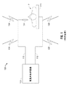
図2は、本開示に従う電気外科システム105を示す。システムは、患者Pの組織を治療するために、1つ以上の電極を有している電気外科器具10を含む単極電気外科システムである。図2、図4および図5を参照すると、電気外科RFエネルギーは、発電機200によって、活性リード18を介して、器具10に供給され、器具10が組織を凝固、切断、切除および/または治療することを可能にする。活性リード18は、発電機200の活性出力端子230(図5)に動作するように接続される。供給および帰還リード18、19は、ケーブル21内に囲まれている。電気外科器具10は、コネクター250または256(図4)において、発電機200に結合され得る。コネクター250または256は、各々、活性端子230に結合される。
FIG. 2 illustrates an
エネルギーは、帰還電極11を通って発電機200に戻され、帰還リード19を通って送信される。帰還リード19は、発電機200の帰還出力端子232(図5)に動作するように接続される。システム105は、複数の帰還電極11を含み得る。複数の帰還電極11は、患者に配置され、患者との全体の接触面積を最大化することによって、組織損傷の可能性を最小化する。帰還電極11は、コネクター254(図4)において発電機200に結合され得る。コネクター254は、帰還端子232に結合される。実施形態において、発電機200および帰還電極11は、いわゆる「組織−患者」接触を監視することによって、間に十分な接触が存在するように保証し、組織損傷の可能性をさらに最小化するように構成され得る。発電機200は、複数の供給および帰還端子ならびに対応する数の送信ケーブル(例えば、各々2本)を含み得る。
The energy is returned to the
図3は、本開示に従う双極電気外科システム102を示す。システム102は、対向するジョー部材を有している電気外科鉗子12を含む双極電気外科システムである。鉗子12は、脈管密閉双極鉗子の内視鏡型を示す。実施形態において、鉗子12は、開放型鉗子のような任意の適切な電気外科密閉器具である。鉗子12は、相互にエンドエフェクタアセンブリ100と協働して、組織を把持、密閉および必要に応じて、分割するハウジング20、ハンドルアセンブリ30、回転アセンブリ80およびトリガーアセンブリ70も含む。鉗子12は、エンドエフェクタアセンブリ100を機械的に係合する遠位端部14と、回転アセンブリ80の直近にあるハウジング20を機械的に係合する近位端部16とを有しているシャフト13を含む。エンドエフェクタアセンブリ100は、2つのジョー部材110、120を含み、2つのジョー部材110、120は、ジョー部材が別のジョー部材に対して一定の距離を置かれた第一の位置から、ジョー部材110および120が協働して、その間に組織を把持する閉鎖位置まで可動である。ジョー部材の各々は、それぞれ、エネルギー供給源(例えば、発電機200)に接続された導電性密閉表面112および122を含む。導電性密閉表面112および122は、その間に保持された組織を通して電気エネルギーを通信する。電気外科RFエネルギーは、発電機200によって、活性リード18を介して、鉗子12に供給され、帰還リード19を通して戻される。活性リード18は、動作するように活性電極(例えば、密閉表面112)に接続される。帰還リード19は、動作するように帰還電極(例えば、密閉表面122)に接続される。
FIG. 3 illustrates a
ハンドルアセンブリ30は、固定ハンドル50および可動ハンドル40を含む。ハンドル40は、固定ハンドル50に対して動き、エンドエフェクタアセンブリ100を作動させ、ユーザーが組織を選択的に把持および操作することを可能にする。ジョー部材110および120は、開放位置から閉鎖位置までのハンドル40の動きに応答して、動く。開放位置において、密閉表面112および122は、互いに対して、一定の距離を置かれた関係に配置される。クランプ締めまたは閉鎖位置において、密閉表面112および122は、協働して、組織を把持し、組織に電気外科エネルギーを適用する。ジョー部材110および120は、ハウジング20内に囲まれた駆動アセンブリ(示されていない)を用いて、作動される。駆動アセンブリは、可動ハンドル40と協働して、開放位置からクランプ締めまたは閉鎖位置までのジョー部材110および120の動きをさせる。ハンドルアセンブリの例は、名称が「Vessel Sealer And Divider And Method Manufacturing Same」の共有に係る米国出願第10/369,894号および名称が「Vessel Sealer And Divider For Use With Small Trocars And Cannulas」の共有に係る米国出願第10/460,926号に示され、記載される。
The
鉗子12は、鉗子12をケーブル21を介して、電気外科エネルギーの供給源(例えば、発電機200)に接続するプラグ23も含む。図3〜図5を参照すると、導電性密閉表面112および122は、ケーブル21を通して、発電機200に接続される。ケーブル21は、それぞれ、活性および帰還端子230、232(図5)に結合された供給および帰還リード18、19を含む。電気外科鉗子12は、プラグ23を介して、コネクター260、262(図4)において、発電機200に結合される。コネクター260、262おの各々は、活性および帰還端子230および232(例えば、ピンなど)に結合される。
The
図4および図5を参照すると、発電機200の正面240が示される。発電機200は、任意の適切な電気外科発電機であり得、さまざまなタイプの電気外科器具(例えば、電気外科鉗子12など)を収容するために、複数のコネクター250〜262を含み得る。コネクター250〜262は、器具のプラグ(例えば、鉗子12のプラグ23)上に符号化された識別情報を読み取ることができるさまざまな検出デバイスを含み得る。コネクター250〜262は、特定の器具の動作パラメータに対応する、プラグ上に符号化された情報を復号化するように構成されており、発電機200が、接続された器具に基づいて、エネルギー搬送設定を予め設定することを可能にする。実施形態において、データは、バーコード、電気的部品(例えば、抵抗器、コンデンサーなど)、RFIDチップ、磁石、不揮発性メモリなどに符号化され得、それらは、次いで、プラグに結合または一体化され得る。対応する検出デバイスは、バーコードリーダー、電気センサー、RFIDリーダー、ホール効果センサー、メモリリーダーなど、およびプラグ上に符号化されたデータを復号化するように構成されている任意の他の適切なデコーダーを含み得るが、それらに限定されない。
With reference to FIGS. 4 and 5, the
発電機200は、ユーザーにさまざまな出力情報(例えば、強度設定、治療完了インジケーターなど)を提供する1つ以上のディスプレイスクリーン242、244、246を含む。スクリーン242、244、246の各々は、対応するコネクター250〜262に関連付けられている。発電機200は、発電機200を制御する適切な入力制御器(例えば、ボタン、アクチベータ、スイッチ、タッチスクリーンなど)を含む。ディスプレイスクリーン242、244、246は、電気外科器具(例えば、電気外科鉗子12など)に対する対応するメニューを表示するタッチスクリーンとしても構成されている。次いで、ユーザーは、単に対応するメニューオプションに触れることによって、入力を行う。
The
スクリーン242は、単極出力と、コネクター250および252に接続されたデバイスとを制御する。コネクター250は、単極電気外科器具(例えば、電気外科ペンシル)に結合するように構成されており、コネクター252は、フットスイッチ(示されていない)に結合するように構成されている。フットスイッチは、追加の入力(例えば、発電機200の複製入力)を提供する。スクリーン244は、単極および双極出力と、コネクター256および258に接続されたデバイスとを制御する。コネクター256は、他の単極器具に結合するように構成されている。コネクター258は、双極器具(示されていない)に結合するように構成されている。
スクリーン246は、鉗子12によって行われる双極密閉処置を制御する。鉗子12は、コネクター260および262にプラグ接続され得る。発電機200は、鉗子12によって把持された組織を密閉することに適切なコネクター260および262を通して、エネルギーを出力する。特に、スクリーン246は、ユーザーがユーザー規定の強度設定を入力することを可能にするユーザーインターフェースを出力する。ユーザー規定の設定は、電力、電流、電圧、エネルギーなどのような1つ以上のエネルギー搬送パラメータまたは圧力、密閉持続時間などのような密閉パラメータを調節することを可能にする任意の設定であり得る。ユーザー規定の設定は、設定がメモリ226に保存され得るコントローラー224に送信される。実施形態において、強度設定は、1から10または1から5のような数値階級であり得る。実施形態において、強度設定は、発電機200の出力曲線に関連付けられ得る。強度設定は、さまざまな器具がユーザーに鉗子12に対応する、特有の強度階級を提供するように、使用されている各鉗子12に特有であり得る。
図5は、電気外科エネルギーを出力するように構成されている発電機200の概略ブロック図を示す。発電機200は、コントローラー224、電力供給部227および出力段228を含む。電力供給部227は、直流高電圧電力供給部であり得、AC供給源(例えば、壁付き電気コンセント)に接続され、高電圧DC電力を出力段228に提供する。次いで、出力段228は、高電圧DC電力を治療エネルギー(例えば、超音波、電気外科またはマイクロ波エネルギー)に変換し、エネルギーを活性端子2230に搬送する。エネルギーは、帰還端子232を介して戻される。出力段228は、複数のモードで動作するように構成されており、その間、発電機200は、特有のデューティサイクル、ピーク電圧、波高率などを有している対応する波形を出力する。別の実施形態において、発電機200は、他のタイプの適切な電力供給トポロジーに基づき得る。
FIG. 5 shows a schematic block diagram of a
コントローラー224は、メモリ226に動作可能に接続されたマイクロプロセッサ225を含む。メモリ226は、一時型メモリ(例えば、RAM)および/または非一時型メモリ(例えば、フラッシュメディア、ディスクメディアなど)を含み得る。マイクロプロセッサ225は、電力供給部227および/または出力段228に動作可能に接続される出力ポートを含み、マイクロプロセッサ225が開および/または閉制御ループスキームの一方に従って、発電機200の出力を制御することを可能にする。当業者は、マイクロプロセッサ225が、本明細書において述べられる計算を行うように適合されている任意の論理プロセッサ(例えば、制御回路)によって、代替され得ることを認識する。
The
閉ループ制御スキームは、複数のセンサーがさまざまな組織およびエネルギー特性(例えば、組織インピーダンス、組織温度、出力電力、電流および/または電圧など)を測定し、フィードバックをコントローラー224に提供するフィードバック制御ループである。次いで、コントローラー224は、電力供給部227および/または出力段228に信号発信し、電力供給部227および/または出力段228は、次いで、それぞれ、DCおよび/または電力供給を調節する。コントローラー224は、発電機200または鉗子12の入力制御器から入力信号も受信する。コントローラー224は、発電機200によって出力された電力を調節するために入力信号を使用するか、および/または他の制御機能をそれらに対して行う。
The closed loop control scheme is a feedback control loop in which multiple sensors measure various tissue and energy characteristics (eg, tissue impedance, tissue temperature, output power, current and / or voltage, etc.) and provide feedback to the
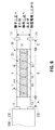
図6は、ケーブル21の断面図を示す。ケーブル21は、それぞれ、活性および帰還端子230、232を介して、発電機200に動作するように接続された供給および帰還リード18、19を含む。供給および帰還リード18、19は、絶縁され得る。さまざまなタイプの絶縁材料が用いられ得、それらは当業者の理解の範囲内である。供給および帰還リード18、19は、それぞれ、距離Aにわたって、活性および帰還端子230、232から延在する。距離Aは、活性および帰還端子230、232の場所によって最適に制御され、約0.1インチから約6インチまでであり得る。次いで、リード18、19は、巻きつけられた部分35において、螺旋状に巻きつけられる。巻きつけられた部分35は、所望のケーブルインダクタンスおよび静電容量に応じて、約0.1インチから約20フィートまでであり得る。あるいは、巻きつけられた部分35は、距離Aにわたって、供給および帰還リード18、19を延在させずに、活性および帰還端子230、232から延在し得る。
FIG. 6 shows a cross-sectional view of the
ケーブル長さBに沿った巻きつけられた部分35は、ケーブル部品の製造の際に用いられる材料の幾何学的構成および物理的特性(例えば、張力強度、可撓性など)に応じて、任意の長さであり得る。より具体的には、リード18、19は、軸に沿った並行移動によって異なる、同じ軸を有している2つの合同な螺旋を含む二重螺旋に配向される。リード18、19は、リード18、19を自身の周りに包装する複数の他の配列にも配向され得る。二重螺旋のリード18、19の配列は、そこを通過する電気外科RFエネルギーによって生成された対向する電場を配向し、損失される漂遊電気RFエネルギーの量を軽減および/または消去することによって最小化する。
The
部分35の距離Dは、1つの螺旋の1つの先端と、別の螺旋の最も近い先端との間の距離を表し、約1/2インチであり得る。距離Eは、同じ螺旋の2つの先端間の距離であり、約1インチであり得る。ケーブル21の外径Fは、所望のケーブルインダクタンス、静電容量または電場最小化に応じて変わり得るか、または約3/8インチであり得る。
The distance D of the
リード18、19は、ケーブル21内において、誘電性コア37の周りに巻きつけられる。誘電性コア37は、リード18、19に支持を提供し、絶縁性シース39は、リード18、19を覆う。誘電性コア37は、低誘電定数材料によって取り囲まれた空気のコアを有している実質的に管状形状を有し得る。シース39は、誘電性コア37と同じタイプの誘電性材料であり得る。リード18、19は、ワイヤーまたは伝導性トレースを含み得、約473kHzで約7.37μHのインダクタンス定格を有し得、約1MHzで約32.0PFの静電容量を有し得ることによって、約10.4MHzのケーブル自己共鳴を生む。
The leads 18 and 19 are wound around the
図6に例示されるようなケーブル21は、RFエネルギーを発電機200から組織部位まで搬送する送信媒体を提供する。ケーブル21は、RF送信媒体に対する一実施形態を表す。RF送信媒体は、放射されたRF電場を減少させ、適用される、組織部位に搬送される臨床治療エネルギーを最大化する。図6の寸法A、B、C、D、EおよびFは、3次元空間において、固有の近位幾何学的関係を形成し、発電機200の活性および帰還出力端子間に結合する電場を制御することによって、ボルトパーメートルおよびアンプパーメトルの電場放射を場の消去によって有意に減少させる。
The
物理的な寸法A、B、C、D、EおよびFは、独立しており、低損失誘導性および静電容量送信媒体を提供するように最適化され得る。低損失誘導性および静電容量送信媒体は、電場を制御することに加えて、漂遊RF放射によって生じた制御されていない静電容量結合を減少させる。特に、以下の式(I)および(II)は、ケーブル21の誘導性および静電容量特性に関して、寸法A、B、C、D、EおよびFの独立した関係を例示する。
(I)インダクタンス=B(10.16×10^−9)Ln[(2×D)/d]+2(A+C)(特有のワイヤーに対してμH/in表記)
(II)静電容量=[(B×(0.7065×10^−12))/Ln[(2×D)/d]]er
式(I)および(II)において、「d」は、ワイヤー(例えば、供給および帰還リード18、19)の直径を意味し、「er」は、絶縁体の誘電定数を意味する。さらに、E=2×D、EからDまでの比率は、螺旋構成の連続を確立し、F=k×Dである。ここで、「k」は、約0.5から約1.5までの定数である。
The physical dimensions A, B, C, D, E and F are independent and can be optimized to provide a low loss inductive and capacitive transmission medium. Low loss inductive and capacitive transmission media reduce uncontrolled capacitive coupling caused by stray RF radiation in addition to controlling the electric field. In particular, the following equations (I) and (II) illustrate the independent relationship of dimensions A, B, C, D, E, and F with respect to the inductive and capacitance characteristics of
(I) Inductance = B (10.16 × 10 ^ −9) Ln [(2 × D) / d] +2 (A + C) (μH / in notation for a specific wire)
(II) Capacitance = [(B × (0.7065 × 10 ^ −12)) / Ln [(2 × D) / d]] er
In formulas (I) and (II), “d” means the diameter of the wire (eg, supply and return leads 18, 19) and “er” means the dielectric constant of the insulator. Furthermore, E = 2 × D, the ratio from E to D establishes a continuous spiral configuration, F = k × D. Here, “k” is a constant from about 0.5 to about 1.5.
部分35の遠位端部において、リード18、19は、巻きつけられておらず、それぞれ、デバイスコネクター33、34に動作するように接続される。デバイスコネクター33、34は、鉗子12内に配置されたピンであり得る。リード18、19は、器具用途に応じた巻きついていない状態の長さにおける、部分35からコネクター33、34までの距離Cを延在する。
At the distal end of
双極電気外科において、コネクター33、34は、鉗子12上に置かれ得る。単極外科手術において、コネクター33は、器具10に動作するように接続され、コネクター34は、帰還電極11に接続される。上記で述べたように、複数の帰還電極が用いられる状況において、帰還リード19は、帰還電極11の全てを発電機200に動作するように接続するために、対応する数のリードに分割され得る。単極外科手術において、リード18および19に対する長さCは、手術部位における外科手術器具の操作を収容するために、等しいまたは異なる長さであり得る。
In bipolar electrosurgery, the
本開示に従うケーブル21は、供給および帰還リード18、19を配向し、その結果、それらを通して生成された電場が消去されることによって、漏れた漂遊RFエネルギーの量を減少させる。より具体的には、上記で述べた態様のリード18、19の設置および配向は、電気外科RFエネルギーの送信の間に生成された電場の近接性を提供し、治療部位に搬送されるエネルギーの量を最大化する。電場を減少させることは、手術室職員および患者の安全性も増加させる。
The
減少されたRF放射は、静電容量およびRF場漏れを減らし、搬送されるエネルギーのRF制御を改善する。減少されたRF放射は、RF送信損失も減らし、RF調波成分を減少させることと、RF供給源の損傷を最小化することと、周辺伝導性および放射性放出を減少させることとによって、発電機200の効率を改善する。さらに、RF放射を減少させることは、患者監視機器のような手術室に見られる追加の機器に対するRFノイズも減らす。 Reduced RF radiation reduces capacitance and RF field leakage and improves RF control of the energy delivered. Reduced RF radiation also reduces RF transmission losses, reduces RF harmonic content, minimizes RF source damage, and reduces peripheral conducted and radiated emissions. Improve the efficiency of 200. In addition, reducing RF emissions also reduces RF noise for additional equipment found in operating rooms such as patient monitoring equipment.
加えて、本開示に従う送信システムは、直接、組織部位において組織およびエネルギーパラメータを感知する新規の方法も提供する。従来の電気外科システムは、電源におけるエネルギー搬送を感知および制御し、組織部位への送信の間のエネルギー損失に対して、較正する。特に、器具への送信および器具からの送信中のエネルギー損失ならびに電源内の内部損失は、次善の方法によって、補われる。したがって、従来の電気外科システムは、組織に適用されるエネルギーを直接は制御しないか、または組織部位におけるエネルギーおよび組織パラメータを監視しない。これらは、次善の組織治療となり得る。 In addition, the transmission system according to the present disclosure also provides a novel method of sensing tissue and energy parameters directly at the tissue site. Conventional electrosurgical systems sense and control energy delivery at the power source and calibrate for energy loss during transmission to the tissue site. In particular, energy losses during transmission to and from the instrument and internal losses in the power supply are compensated by sub-optimal methods. Thus, conventional electrosurgical systems do not directly control the energy applied to the tissue or monitor energy and tissue parameters at the tissue site. These can be sub-optimal tissue treatments.
本開示は、直接、組織部位における組織およびエネルギーパラメータを感知するシステムを提供し、適用されるエネルギーの誤差のないフィードバック制御を可能にすることによって、止血、脈管密閉および凝固を含むが、これらに限定されない所望の組織治療効果を最適に達成する。特に、本開示は、さまざまな組織およびエネルギーパラメータを感知するために、治療部位に配置されたセンサーを含み、電圧および電流電磁場成分を最小化することと、感知された信号完全性を最大化することとのために、送信媒体(例えば、ケーブル21)を使用する。次いで、感知された信号は、最小または無視可能損失、もしくは従来の信号劣化、上記に記載した従来の損失を有している送信媒体を通して、電源に送信される。電気外科エネルギーを発電機から器具まで送信する能力を有している送信媒体は、名称が「Electrosurgical Radio Frequency Energy Transmission Medium」の共有に係る米国特許第7,819,865号に開示され、その全内容は、本明細書において、参照することによって援用される。 The present disclosure provides a system that directly senses tissue and energy parameters at a tissue site, including hemostasis, vascular sealing, and coagulation by allowing error-free feedback control of applied energy. Optimally achieving the desired tissue treatment effect, not limited to: In particular, the present disclosure includes a sensor disposed at the treatment site to sense various tissue and energy parameters to minimize voltage and current electromagnetic field components and maximize sensed signal integrity. For this purpose, a transmission medium (eg cable 21) is used. The sensed signal is then transmitted to the power source through a transmission medium having minimal or negligible loss, or conventional signal degradation, the conventional loss described above. A transmission medium having the ability to transmit electrosurgical energy from a generator to an instrument is disclosed in US Pat. No. 7,819,865, whose name is “Electrosurgical Radio Frequency Energy Transmission Medium” sharing. The contents of which are incorporated herein by reference.
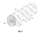
図7は、発電機200および鉗子10を含むシステム300を示す。鉗子10は、概略的に、1対の対向するジョー部材110および120として示され、各ジョー部材は、導電性密閉表面112および122を有している。システム300は、直接、組織部位Tにおいて感知された組織およびエネルギー特性に基づく閉ループ態様で、治療エネルギー(例えば、発電機200の出力)の制御を提供する。システム300によって調節され得る治療エネルギーのパラメータは、エネルギー、電力、電圧、電流、組織インピーダンスおよびパラメータ時間、これらのパラメータの変化の比率、およびそれらの組合わせを含むが、それらに限定されない。測定された組織およびエネルギー特性は、組織インピーダンス、組織半透明性/不透明性、組織水文学、組織、血管分布、密閉された脈管の破裂強度、組織密閉癒合、温度、適用された治療エネルギーによる組織貫通の深さ、熱の広がり、およびそれらの組合わせを含むが、それらに限定されない。システム300は、直接、組織部位における組織およびエネルギー特性を検出し、センサー測定値を電気および/または光学ケーブルに沿って、発電機200に送信する光学および電気センサーを含む。図7および図8を参照すると、ケーブル(例えば、光学送信線356および/または電気センサー線344)は、巻きつけられたRF供給および帰還リード318、319の送信媒体内に配置されており、組織部位センサー信号劣化を最小化し、組織感知デバイスのマルチセンサー通信を可能にする。特に、送信媒体は、組織の送信、反射、スペクトルおよび視覚分析を可能にする光学ファイバーの使用を可能にする。
FIG. 7 shows a
鉗子10は、ケーブル321を介して発電機に結合される。発電機200は、供給および帰還リード318、319に結合された出力段228を含む。供給および帰還リード318、319は、ケーブル321内に配置される。供給および帰還リード318、319は、それぞれ、活性および帰還端子230、232を介して、発電機200に動作するように接続される。ケーブル321は、上記で図6を参照して、上記に記載したケーブル21に実質的に類似する。したがって、ケーブル21の実施形態は、リード18、19、誘電性コア37、絶縁性シース39など、ならびに構成、配列およびこれらの部品の材料特性のようなケーブル21の素子を含むが、それらに限定されないケーブル321の実施形態に組み込まれる。
The
ケーブル321は、ケーブル321のコアを形成する誘電性コア337を含む。供給および帰還リード318および319は、誘電性コア337の周りにおいて、二重螺旋態様で巻きつけられ、図6のリード18および19に類似する構成に配列される。誘電性コア337は、実質的に管状構造を有しており、管状構造は、管状構造を通って規定される管腔338を有している。二重螺旋のリード318、319の配列は、そこを通過する電気外科RFエネルギーによって生成された対向する電場を配向し、損失される漂遊電気RFエネルギーの量を軽減および/または消去することによって、最小化する。ケーブル321は、リード318および319を覆って配置される絶縁性シース339も含むことによって、リード318および319を誘電性コア337に固定する。
図7に例示されるようなケーブル321は、RFエネルギーを発電機200からジョー部材110と120との間に把持された組織Tまで搬送する送信媒体を提供する。鉗子10は、供給および帰還リード318と319との間に接続された1つ以上の電気センサー340および341を含む。電気センサー340および341は、組織接触部分113(つまり、ジョー部材110および120)に配置される。電気センサー340および341は、伝導性抵抗器、感知変圧器、熱インピーダンスデバイス、既知の抵抗および熱インピーダンスを有している複合材料、およびそれらの組合わせを含むが、それらに限定されない任意の適切な電気感知変換器であり得る。電気センサー340および341は、ジョー部材110および120の一方または両方の中に配置され得、それぞれ、導電性密閉表面112および122と電気通信する。この構成は、電気センサー340および341が組織インピーダンス、電力、電圧、電流、抵抗、位相、温度、(例えば、コントローラー224によって計算されるような)それらの変化の時間パラメータ比率およびそれらの組合わせを検出することを可能にする。電気センサー340および341は、従来の電気外科システムにおいて行われるような、エネルギー感知情報を発電機200において測定せずに、導電性密閉表面112および122を直接通過するそれらの特性を測定する。電気センサー340および341は、上記感知情報および導電性密閉表面112および122を通して組織Tまで搬送された電気外科エネルギーの他の電気特性を測定し得る。次いで、測定されたパラメータは、上記に記載されたさまざまな組織およびエネルギー特性を決定するために用いられ得る。
A
電気センサー340および341は、1つ以上の電気センサー線344を介して、電気感知プロセッサ342に結合される。図8に示されるように、線344は、ケーブル321内に配置され、管腔338を通過する。線344は、絶縁され得る。さまざまなタイプの絶縁材料が用いられ得、それらは、当業者の理解の範囲内である。感知プロセッサ342は、発電機200内に配置され、コントローラー224に結合される。感知プロセッサ342は、電気感知信号を電気センサー340および341から受信し、組織Tにおける組織および/またはエネルギーパラメータを決定し、次いで、処理された感知信号をコントローラー224に送信する。実施形態において、電気センサー340および341は、コントローラー224が感知プロセッサ342の機能性(つまり、電気感知信号に基づく、組織およびエネルギーパラメータの決定)を行うように、コントローラー224(例えば、隔離されている)に結合され得る。
鉗子10は、組織接触部分113において、1つ以上の光学センサーアレイ350および352も含み、それぞれ、ジョー部材110および120内に配置される。センサーアレイ350および352は、組織Tと直接接触構成または非接触構成(例えば、密閉プレート112および122によって、分離される)に配置され得る。各アレイ350および352は、それぞれ、複数の光学センサー350a、350bおよび352a、352bを含み得る。適切な光学センサーは、個別の光子が別々の効果を発生させる量子デバイスである光学検出器、抵抗が光強度の関数であるフォトレジスターまたは光依存抵抗器、光起電性モードまたは光伝導性モードで動作するフォトダイオード、照射された場合に電圧および電流を発生する光起電力電池、光電陰極を含むフォトセンサーセル、フォトダイオードとして作用するように逆バイアスがかけられた発光デバイス(LED)、フォトダイオードを増幅するものとして機能するフォトトランジスタ、入り放射の熱を電流に変換する温度計として機能する光学検出器などを含むが、それらに限定されない。
The
各アレイ350および352は、1つ以上の光学送信器351および353も含む。適切な光学送信器は、発光ダイオード(LED)のような発光電子デバイスまたは光源からの光学情報を提供する電気信号を送信する電気ケーブルを含むが、それらに限定されない。実施形態において、光学送信器351および353は、交互に光学センサー350a、350bおよび352a、352bとしても機能し得、二重機能光学送信器および光学受信器として働く。さらなる実施形態において、二重機能光学送信器および光学受信器は、マルチプレクサデバイスを含み得る。
Each
実施形態において、光学センサー350a、350bおよび352a、352bならびに光学送信器351および353は、組織Tと光学通信する。このことは、光学センサー350a、350bおよび352a、352bならびに光学送信器351および353の各々に対して透明な開口部を含むことによって、実現され得る。実施形態において、光学センサー350a、350bおよび352a、352bならびに光学送信器351および353は、小径光学ファイバーを含むが、それに限定されない光学送信媒体を介して、開口部に結合され得る。小径光学ファイバーは、送信または反射モードの一方で、そこを通り伝わる光によって、組織T特性と位相相関するブラッグ格子を組み込む。
In an embodiment,
光学センサー350a、350bおよび352a、352bならびに光学送信器351および353は、組織の送信、反射、スペクトルおよび視覚分析のために構成され得る。送信分析において、光学センサー350aおよび350bは、光学送信器353による組織Tを通る光送信を検出し、光学センサー352aおよび352bは、光学送信器351による組織Tを通る光送信を検出する。反射分析において、光学センサー350aおよび350bは、組織Tに反射した光を検出する。光学センサー352aおよび352bは、組織Tを反射した光を検出する。スペクトル分析において、光学センサー350a、350bおよび352a、352bは、光学送信器351および353の一方によって放出された光を検出し得る。視覚分析において、光学センサー350a、350bおよび352a、352bは、画像出力デバイス(例えば、モニター)に結合された相補型金属酸化物半導体(「CMOS」)または電荷結合デバイス(「CCD」)センサーのような任意の画像センサーであり得る。
光学センサー350a、350bおよび352a、352bならびに光学送信器351および353は、図7および図8に示されるような1つ以上の光学送信線356を介して、照明供給源354および照明感知プロセッサ358に結合される。適切な光学送信線356は、光学センサー350a、350bおよび352a、352bと照明供給源354との間に光学通信を提供する能力を有している光学センサーまたは導電性ケーブルに関して上記したような光学ファイバーを含む。
照明供給源354は、光を光学送信器351および353を通して、組織Tに供給する。組織Tを通って伝わる光は、光学センサー350a、350bおよび352a、352bによって検出され、光子信号を電気信号に変換する。次いで、電気信号は、感知プロセッサ358に送信される。感知プロセッサ358は、組織治療に応答して、組織Tを通る光の変化を感知することと、そのような変化をコントローラー224に通信し、透過率、反射率、半透明性、不透明性、水文学、血管分布、熱の広がり、組織治療深さ、組織密閉の質、温度、スペクトルの内容、およびそれらの組合わせを含むが、それらに限定されない組織特性を決定することとを行うように構成されている。実施形態において、光学センサー350a、350bおよび352a、352bならびに光学送信器351および353は、コントローラー224が感知プロセッサ358の機能性(つまり、光学感知信号に基づく組織およびエネルギーパラメータの決定)を行うように、コントローラー224に直接結合され得る。
The
電気および光学感知信号に応答して、コントローラー224は、発電機200の出力を調節し得る。実施形態において、コントローラー224は、検出された組織および/またはエネルギー特性の関数として出力を制御する1つ以上のアルゴリズムを含み得る。特に、コントローラー224に実装されるアルゴリズムは、発電機200、および照明供給源354、照明感知プロセッサ358および電気感知プロセッサ342を含む発電機200の部品の出力を駆動し得ることによって、組織および/またはエネルギー特性を発電機出力の調節のために継続的に監視する。
In response to the electrical and optical sensing signals, the
光学センサーを介した電気外科適用中に組織を監視するシステムおよび方法は、名称が「Apparatus, System And Method For Monitoring Tissue During An Electrosurgical Procedure」の共有に係る米国特許出願第12/249,263号に開示され、その全内容は、本明細書において、参照することによって援用される。 A system and method for monitoring tissue during electrosurgical application via an optical sensor is described in U.S. Patent Application No. 12/249, sharing the name "Apparatus, System And Method For Monitoring Tissue During An Electroprocedure". The entire contents of which are disclosed and incorporated herein by reference.
開示の複数の実施形態が図面において示されるか、および/または本明細書において述べられたが、開示がそれらに限定されることは意図されていない。開示は、当分野が許容する限り範囲が広いことを意図しており、明細書も同様に読まれることが意図される。そのため、上記の記載は、限定ではなく、特定の実施形態の単なる例示として解釈されるべきである。当業者は、他の改変を、本明細書に添付の請求項の範囲および精神内に想定する。 Although several embodiments of the disclosure are shown in the drawings and / or described herein, it is not intended that the disclosure be limited thereto. The disclosure is intended to be as broad as the art allows, and the specification is intended to be read as well. Therefore, the above description should not be construed as limiting, but merely as exemplifications of particular embodiments. Those skilled in the art will envision other modifications within the scope and spirit of the claims appended hereto.
Claims (16)
該少なくとも1つの活性リードおよび該少なくとも1つの帰還リードに結合されている電気外科器具であって、該電気外科器具は、少なくとも1つのセンサーを含み、該少なくとも1つのセンサーは、組織接触部分に配置され、少なくとも1つのセンサー線を通して該発電機に結合されている、電気外科器具と、
誘電性コアを含む電気外科ケーブルと
を含み、該少なくとも1つのセンサー線は、該誘電性コア内に配置され、該少なくとも1つの活性リードおよび該少なくとも1つの帰還リードの各々の少なくとも一部が二重螺旋状に該誘電性コアの周りに巻きつけられることにより、該少なくとも1つの活性リードおよび該少なくとも1つの帰還リードによって生成された電場を最小化する、電気外科システム。 A generator comprising at least one active output terminal coupled to at least one active lead and at least one feedback output terminal coupled to at least one feedback lead;
An electrosurgical instrument coupled to the at least one active lead and the at least one return lead, the electrosurgical instrument including at least one sensor, the at least one sensor disposed at the tissue contacting portion An electrosurgical instrument coupled to the generator through at least one sensor line;
An electrosurgical cable including a dielectric core, wherein the at least one sensor wire is disposed within the dielectric core, and at least a portion of each of the at least one active lead and the at least one return lead is duplicated. An electrosurgical system that is wrapped around the dielectric core in a helical fashion to minimize the electric field generated by the at least one active lead and the at least one feedback lead.
電気外科鉗子と、
誘電性コアを含む電気外科ケーブルと
を含む、電気外科システムであって、
該電気外科鉗子は、
2つのジョー部材であって、該2つのジョー部材の少なくとも一方は、他方に対して一定の距離を置かれた関係の第一の位置から、該ジョー部材が協働して該ジョー部材の間で組織を把持する少なくとも1つの後続する位置まで可動であり、該ジョー部材の各々は、導電性密閉表面を含み、1つの導電性密閉表面は、該少なくとも1つの活性リードに結合されており、別の導電性密閉表面は、該少なくとも1つの帰還リードに結合されている、2つのジョー部材と、
該ジョー部材の少なくとも一方の中に配置された少なくとも1つのセンサーであって、該少なくとも1つのセンサーは、少なくとも1つのセンサー線を通して該発電機に結合されている、少なくとも1つのセンサーと
を含み、
該少なくとも1つのセンサー線は、該誘電性コア内に配置され、該少なくとも1つの活性リードおよび該少なくとも1つの帰還リードの各々の少なくとも一部が二重螺旋状に該誘電性コアの周りに巻きつけられることにより、該少なくとも1つの活性リードおよび該少なくとも1つの帰還リードによって生成された電場を最小化する、電気外科システム。 A generator comprising at least one active output terminal coupled to at least one active lead and at least one feedback output terminal coupled to at least one feedback lead;
Electrosurgical forceps,
An electrosurgical system comprising: an electrosurgical cable including a dielectric core;
The electrosurgical forceps
Two jaw members, wherein at least one of the two jaw members cooperates between the jaw members from a first position in a fixed distance relative to the other. Each of the jaw members includes a conductive sealing surface, wherein the one conductive sealing surface is coupled to the at least one active lead; Another conductive sealing surface is coupled to the at least one return lead, two jaw members;
At least one sensor disposed in at least one of the jaw members, the at least one sensor including at least one sensor coupled to the generator through at least one sensor line;
The at least one sensor line is disposed within the dielectric core, and at least a portion of each of the at least one active lead and the at least one return lead is wound around the dielectric core in a double helix. An electrosurgical system that, when applied, minimizes the electric field generated by the at least one active lead and the at least one return lead.
電気外科鉗子と、
誘電性コアを含む電気外科ケーブルと
を含む、電気外科システムであって、
該電気外科鉗子は、
2つのジョー部材であって、該2つのジョー部材の少なくとも一方は、他方に対して、一定の距離を置かれた関係の第一の位置から、該ジョー部材が協働して該ジョー部材の間で組織を把持する少なくとも1つの後続する位置まで可動であり、該ジョー部材の各々は、導電性密閉表面を含み、1つの導電性密閉表面は、該少なくとも1つの活性リードに結合されており、別の導電性密閉表面は、該少なくとも1つの帰還リードに結合されている、2つのジョー部材と、
該ジョー部材の少なくとも一方の中に配置された少なくとも1つの電気センサーであって、該少なくとも1つの電気センサーは、少なくとも1つの電気センサー線を通して、該導電性密閉表面の少なくとも一方と、該発電機とに結合されている、少なくとも1つの電気センサーと、
該ジョー部材の少なくとも一方の中に配置された少なくとも1つの光学センサーであって、該少なくとも1つの光学センサーは、少なくとも1つの光学送信線を通して、該発電機に結合されている、少なくとも1つの光学センサーと、
を含み、
該少なくとも1つのセンサー線は、該誘電性コア内に配置され、該少なくとも1つの活性リードおよび該少なくとも1つの帰還リードの各々の少なくとも一部が二重螺旋状に該誘電性コアの周りに巻きつけられることにより、該少なくとも1つの活性リードおよび該少なくとも1つの帰還リードによって生成された電場を最小化する、電気外科システム。 A generator comprising at least one active output terminal coupled to at least one active lead and at least one feedback output terminal coupled to at least one feedback lead;
Electrosurgical forceps,
An electrosurgical system comprising: an electrosurgical cable including a dielectric core;
The electrosurgical forceps
Two jaw members, at least one of the two jaw members cooperating with the jaw member from a first position in a fixed distance relative to the other. Moveable to at least one subsequent position to grip tissue therebetween, each of the jaw members including a conductive sealing surface, wherein the conductive sealing surface is coupled to the at least one active lead Another conductive sealing surface coupled to the at least one return lead, two jaw members;
At least one electrical sensor disposed in at least one of the jaw members, the at least one electrical sensor passing through at least one electrical sensor wire and at least one of the conductive sealing surface and the generator; At least one electrical sensor coupled to
At least one optical sensor disposed in at least one of the jaw members, wherein the at least one optical sensor is coupled to the generator through at least one optical transmission line. A sensor,
Including
The at least one sensor line is disposed within the dielectric core, and at least a portion of each of the at least one active lead and the at least one return lead is wound around the dielectric core in a double helix. An electrosurgical system that, when applied, minimizes the electric field generated by the at least one active lead and the at least one return lead.
Applications Claiming Priority (2)
| Application Number | Priority Date | Filing Date | Title |
|---|---|---|---|
| US13/118,973 | 2011-05-31 | ||
| US13/118,973 US9050089B2 (en) | 2011-05-31 | 2011-05-31 | Electrosurgical apparatus with tissue site sensing and feedback control |
Publications (2)
| Publication Number | Publication Date |
|---|---|
| JP2012250039A true JP2012250039A (en) | 2012-12-20 |
| JP6063151B2 JP6063151B2 (en) | 2017-01-18 |
Family
ID=46245471
Family Applications (1)
| Application Number | Title | Priority Date | Filing Date |
|---|---|---|---|
| JP2012123174A Expired - Fee Related JP6063151B2 (en) | 2011-05-31 | 2012-05-30 | Electrosurgical device having tissue site sensing and feedback control |
Country Status (5)
| Country | Link |
|---|---|
| US (1) | US9050089B2 (en) |
| EP (1) | EP2529687B1 (en) |
| JP (1) | JP6063151B2 (en) |
| AU (1) | AU2012203166B2 (en) |
| CA (1) | CA2778509C (en) |
Cited By (2)
| Publication number | Priority date | Publication date | Assignee | Title |
|---|---|---|---|---|
| JP2019510543A (en) * | 2016-02-23 | 2019-04-18 | コヴィディエン リミテッド パートナーシップ | Common connector for monopolar and bipolar instruments |
| JP2021511931A (en) * | 2018-01-23 | 2021-05-13 | アピックス メディカル コーポレーション | Skin condition monitoring equipment and methods for electrosurgical equipment |
Families Citing this family (313)
| Publication number | Priority date | Publication date | Assignee | Title |
|---|---|---|---|---|
| US20070084897A1 (en) | 2003-05-20 | 2007-04-19 | Shelton Frederick E Iv | Articulating surgical stapling instrument incorporating a two-piece e-beam firing mechanism |
| US9060770B2 (en) | 2003-05-20 | 2015-06-23 | Ethicon Endo-Surgery, Inc. | Robotically-driven surgical instrument with E-beam driver |
| US7396336B2 (en) | 2003-10-30 | 2008-07-08 | Sherwood Services Ag | Switched resonant ultrasonic power amplifier system |
| US11890012B2 (en) | 2004-07-28 | 2024-02-06 | Cilag Gmbh International | Staple cartridge comprising cartridge body and attached support |
| US8215531B2 (en) | 2004-07-28 | 2012-07-10 | Ethicon Endo-Surgery, Inc. | Surgical stapling instrument having a medical substance dispenser |
| US10159482B2 (en) | 2005-08-31 | 2018-12-25 | Ethicon Llc | Fastener cartridge assembly comprising a fixed anvil and different staple heights |
| US7669746B2 (en) | 2005-08-31 | 2010-03-02 | Ethicon Endo-Surgery, Inc. | Staple cartridges for forming staples having differing formed staple heights |
| US11246590B2 (en) | 2005-08-31 | 2022-02-15 | Cilag Gmbh International | Staple cartridge including staple drivers having different unfired heights |
| US9237891B2 (en) | 2005-08-31 | 2016-01-19 | Ethicon Endo-Surgery, Inc. | Robotically-controlled surgical stapling devices that produce formed staples having different lengths |
| US11484312B2 (en) | 2005-08-31 | 2022-11-01 | Cilag Gmbh International | Staple cartridge comprising a staple driver arrangement |
| US7934630B2 (en) | 2005-08-31 | 2011-05-03 | Ethicon Endo-Surgery, Inc. | Staple cartridges for forming staples having differing formed staple heights |
| US20070106317A1 (en) | 2005-11-09 | 2007-05-10 | Shelton Frederick E Iv | Hydraulically and electrically actuated articulation joints for surgical instruments |
| US20120292367A1 (en) | 2006-01-31 | 2012-11-22 | Ethicon Endo-Surgery, Inc. | Robotically-controlled end effector |
| US7845537B2 (en) | 2006-01-31 | 2010-12-07 | Ethicon Endo-Surgery, Inc. | Surgical instrument having recording capabilities |
| US11278279B2 (en) | 2006-01-31 | 2022-03-22 | Cilag Gmbh International | Surgical instrument assembly |
| US8820603B2 (en) | 2006-01-31 | 2014-09-02 | Ethicon Endo-Surgery, Inc. | Accessing data stored in a memory of a surgical instrument |
| US8708213B2 (en) | 2006-01-31 | 2014-04-29 | Ethicon Endo-Surgery, Inc. | Surgical instrument having a feedback system |
| US11224427B2 (en) | 2006-01-31 | 2022-01-18 | Cilag Gmbh International | Surgical stapling system including a console and retraction assembly |
| US7753904B2 (en) | 2006-01-31 | 2010-07-13 | Ethicon Endo-Surgery, Inc. | Endoscopic surgical instrument with a handle that can articulate with respect to the shaft |
| US11793518B2 (en) | 2006-01-31 | 2023-10-24 | Cilag Gmbh International | Powered surgical instruments with firing system lockout arrangements |
| US20110290856A1 (en) | 2006-01-31 | 2011-12-01 | Ethicon Endo-Surgery, Inc. | Robotically-controlled surgical instrument with force-feedback capabilities |
| US8186555B2 (en) | 2006-01-31 | 2012-05-29 | Ethicon Endo-Surgery, Inc. | Motor-driven surgical cutting and fastening instrument with mechanical closure system |
| US8992422B2 (en) | 2006-03-23 | 2015-03-31 | Ethicon Endo-Surgery, Inc. | Robotically-controlled endoscopic accessory channel |
| US8322455B2 (en) | 2006-06-27 | 2012-12-04 | Ethicon Endo-Surgery, Inc. | Manually driven surgical cutting and fastening instrument |
| CN103222894B (en) | 2006-06-28 | 2015-07-01 | 美敦力Af卢森堡公司 | Methods and systems for thermally-induced renal neuromodulation |
| US7819865B2 (en) | 2006-09-20 | 2010-10-26 | Covidien Ag | Electrosurgical radio frequency energy transmission medium |
| US10568652B2 (en) | 2006-09-29 | 2020-02-25 | Ethicon Llc | Surgical staples having attached drivers of different heights and stapling instruments for deploying the same |
| US8684253B2 (en) | 2007-01-10 | 2014-04-01 | Ethicon Endo-Surgery, Inc. | Surgical instrument with wireless communication between a control unit of a robotic system and remote sensor |
| US8652120B2 (en) | 2007-01-10 | 2014-02-18 | Ethicon Endo-Surgery, Inc. | Surgical instrument with wireless communication between control unit and sensor transponders |
| US11291441B2 (en) | 2007-01-10 | 2022-04-05 | Cilag Gmbh International | Surgical instrument with wireless communication between control unit and remote sensor |
| US20080169332A1 (en) | 2007-01-11 | 2008-07-17 | Shelton Frederick E | Surgical stapling device with a curved cutting member |
| US20090001121A1 (en) | 2007-03-15 | 2009-01-01 | Hess Christopher J | Surgical staple having an expandable portion |
| US11672531B2 (en) | 2007-06-04 | 2023-06-13 | Cilag Gmbh International | Rotary drive systems for surgical instruments |
| US8931682B2 (en) | 2007-06-04 | 2015-01-13 | Ethicon Endo-Surgery, Inc. | Robotically-controlled shaft based rotary drive systems for surgical instruments |
| US11849941B2 (en) | 2007-06-29 | 2023-12-26 | Cilag Gmbh International | Staple cartridge having staple cavities extending at a transverse angle relative to a longitudinal cartridge axis |
| US9179912B2 (en) | 2008-02-14 | 2015-11-10 | Ethicon Endo-Surgery, Inc. | Robotically-controlled motorized surgical cutting and fastening instrument |
| US7819298B2 (en) | 2008-02-14 | 2010-10-26 | Ethicon Endo-Surgery, Inc. | Surgical stapling apparatus with control features operable with one hand |
| US7866527B2 (en) | 2008-02-14 | 2011-01-11 | Ethicon Endo-Surgery, Inc. | Surgical stapling apparatus with interlockable firing system |
| BRPI0901282A2 (en) | 2008-02-14 | 2009-11-17 | Ethicon Endo Surgery Inc | surgical cutting and fixation instrument with rf electrodes |
| US8636736B2 (en) | 2008-02-14 | 2014-01-28 | Ethicon Endo-Surgery, Inc. | Motorized surgical cutting and fastening instrument |
| US10390823B2 (en) | 2008-02-15 | 2019-08-27 | Ethicon Llc | End effector comprising an adjunct |
| US8210411B2 (en) | 2008-09-23 | 2012-07-03 | Ethicon Endo-Surgery, Inc. | Motor-driven surgical cutting instrument |
| US9005230B2 (en) | 2008-09-23 | 2015-04-14 | Ethicon Endo-Surgery, Inc. | Motorized surgical instrument |
| US11648005B2 (en) | 2008-09-23 | 2023-05-16 | Cilag Gmbh International | Robotically-controlled motorized surgical instrument with an end effector |
| US9386983B2 (en) | 2008-09-23 | 2016-07-12 | Ethicon Endo-Surgery, Llc | Robotically-controlled motorized surgical instrument |
| US8608045B2 (en) | 2008-10-10 | 2013-12-17 | Ethicon Endo-Sugery, Inc. | Powered surgical cutting and stapling apparatus with manually retractable firing system |
| US8517239B2 (en) | 2009-02-05 | 2013-08-27 | Ethicon Endo-Surgery, Inc. | Surgical stapling instrument comprising a magnetic element driver |
| US8423182B2 (en) | 2009-03-09 | 2013-04-16 | Intuitive Surgical Operations, Inc. | Adaptable integrated energy control system for electrosurgical tools in robotic surgical systems |
| US8851354B2 (en) | 2009-12-24 | 2014-10-07 | Ethicon Endo-Surgery, Inc. | Surgical cutting instrument that analyzes tissue thickness |
| EP2523620B1 (en) | 2010-01-15 | 2019-06-19 | Medtronic Advanced Energy LLC | Electrosurgical device |
| US8783543B2 (en) | 2010-07-30 | 2014-07-22 | Ethicon Endo-Surgery, Inc. | Tissue acquisition arrangements and methods for surgical stapling devices |
| US11812965B2 (en) | 2010-09-30 | 2023-11-14 | Cilag Gmbh International | Layer of material for a surgical end effector |
| US9386988B2 (en) | 2010-09-30 | 2016-07-12 | Ethicon End-Surgery, LLC | Retainer assembly including a tissue thickness compensator |
| US9629814B2 (en) | 2010-09-30 | 2017-04-25 | Ethicon Endo-Surgery, Llc | Tissue thickness compensator configured to redistribute compressive forces |
| US10945731B2 (en) | 2010-09-30 | 2021-03-16 | Ethicon Llc | Tissue thickness compensator comprising controlled release and expansion |
| US9861361B2 (en) | 2010-09-30 | 2018-01-09 | Ethicon Llc | Releasable tissue thickness compensator and fastener cartridge having the same |
| US11849952B2 (en) | 2010-09-30 | 2023-12-26 | Cilag Gmbh International | Staple cartridge comprising staples positioned within a compressible portion thereof |
| US11298125B2 (en) | 2010-09-30 | 2022-04-12 | Cilag Gmbh International | Tissue stapler having a thickness compensator |
| US8864009B2 (en) | 2010-09-30 | 2014-10-21 | Ethicon Endo-Surgery, Inc. | Tissue thickness compensator for a surgical stapler comprising an adjustable anvil |
| US9839420B2 (en) | 2010-09-30 | 2017-12-12 | Ethicon Llc | Tissue thickness compensator comprising at least one medicament |
| US8695866B2 (en) | 2010-10-01 | 2014-04-15 | Ethicon Endo-Surgery, Inc. | Surgical instrument having a power control circuit |
| JP6046041B2 (en) | 2010-10-25 | 2016-12-14 | メドトロニック アーディアン ルクセンブルク ソシエテ ア レスポンサビリテ リミテ | Devices, systems, and methods for neuromodulation therapy evaluation and feedback |
| US8968293B2 (en) | 2011-04-12 | 2015-03-03 | Covidien Lp | Systems and methods for calibrating power measurements in an electrosurgical generator |
| JP6026509B2 (en) | 2011-04-29 | 2016-11-16 | エシコン・エンド−サージェリィ・インコーポレイテッドEthicon Endo−Surgery,Inc. | Staple cartridge including staples disposed within a compressible portion of the staple cartridge itself |
| US11207064B2 (en) | 2011-05-27 | 2021-12-28 | Cilag Gmbh International | Automated end effector component reloading system for use with a robotic system |
| US9072535B2 (en) | 2011-05-27 | 2015-07-07 | Ethicon Endo-Surgery, Inc. | Surgical stapling instruments with rotatable staple deployment arrangements |
| US9050089B2 (en) | 2011-05-31 | 2015-06-09 | Covidien Lp | Electrosurgical apparatus with tissue site sensing and feedback control |
| US10376301B2 (en) | 2011-09-28 | 2019-08-13 | Covidien Lp | Logarithmic amplifier, electrosurgical generator including same, and method of controlling electrosurgical generator using same |
| US9693816B2 (en) * | 2012-01-30 | 2017-07-04 | Covidien Lp | Electrosurgical apparatus with integrated energy sensing at tissue site |
| JP5904829B2 (en) * | 2012-03-12 | 2016-04-20 | オリンパス株式会社 | Endoscope system |
| US9375282B2 (en) * | 2012-03-26 | 2016-06-28 | Covidien Lp | Light energy sealing, cutting and sensing surgical device |
| BR112014024098B1 (en) | 2012-03-28 | 2021-05-25 | Ethicon Endo-Surgery, Inc. | staple cartridge |
| JP6305979B2 (en) | 2012-03-28 | 2018-04-04 | エシコン・エンド−サージェリィ・インコーポレイテッドEthicon Endo−Surgery,Inc. | Tissue thickness compensator with multiple layers |
| US9375250B2 (en) | 2012-04-09 | 2016-06-28 | Covidien Lp | Method for employing single fault safe redundant signals |
| SG11201407873RA (en) * | 2012-05-29 | 2014-12-30 | Autonomix Medical Inc | Endoscopic sympathectomy systems and methods |
| US9101358B2 (en) | 2012-06-15 | 2015-08-11 | Ethicon Endo-Surgery, Inc. | Articulatable surgical instrument comprising a firing drive |
| BR112014032776B1 (en) | 2012-06-28 | 2021-09-08 | Ethicon Endo-Surgery, Inc | SURGICAL INSTRUMENT SYSTEM AND SURGICAL KIT FOR USE WITH A SURGICAL INSTRUMENT SYSTEM |
| US20140001231A1 (en) | 2012-06-28 | 2014-01-02 | Ethicon Endo-Surgery, Inc. | Firing system lockout arrangements for surgical instruments |
| US20140001234A1 (en) | 2012-06-28 | 2014-01-02 | Ethicon Endo-Surgery, Inc. | Coupling arrangements for attaching surgical end effectors to drive systems therefor |
| US9649111B2 (en) | 2012-06-28 | 2017-05-16 | Ethicon Endo-Surgery, Llc | Replaceable clip cartridge for a clip applier |
| EP2866686A1 (en) | 2012-06-28 | 2015-05-06 | Ethicon Endo-Surgery, Inc. | Empty clip cartridge lockout |
| US9289256B2 (en) | 2012-06-28 | 2016-03-22 | Ethicon Endo-Surgery, Llc | Surgical end effectors having angled tissue-contacting surfaces |
| US11202631B2 (en) | 2012-06-28 | 2021-12-21 | Cilag Gmbh International | Stapling assembly comprising a firing lockout |
| US9301811B2 (en) | 2012-09-17 | 2016-04-05 | Intuitive Surgical Operations, Inc. | Methods and systems for assigning input devices to teleoperated surgical instrument functions |
| US9649146B2 (en) | 2012-10-02 | 2017-05-16 | Covidien Lp | Electro-thermal device |
| US10631939B2 (en) * | 2012-11-02 | 2020-04-28 | Intuitive Surgical Operations, Inc. | Systems and methods for mapping flux supply paths |
| US10864048B2 (en) | 2012-11-02 | 2020-12-15 | Intuitive Surgical Operations, Inc. | Flux disambiguation for teleoperated surgical systems |
| JP6345707B2 (en) | 2013-03-01 | 2018-06-20 | エシコン・エンド−サージェリィ・インコーポレイテッドEthicon Endo−Surgery,Inc. | Surgical instrument with soft stop |
| BR112015021098B1 (en) | 2013-03-01 | 2022-02-15 | Ethicon Endo-Surgery, Inc | COVERAGE FOR A JOINT JOINT AND SURGICAL INSTRUMENT |
| US9629629B2 (en) | 2013-03-14 | 2017-04-25 | Ethicon Endo-Surgey, LLC | Control systems for surgical instruments |
| US9482658B2 (en) | 2013-03-25 | 2016-11-01 | Ohio University | Test system and method for determining thermal effects of tissue ablation on an ex vivo tissue |
| US9867612B2 (en) | 2013-04-16 | 2018-01-16 | Ethicon Llc | Powered surgical stapler |
| BR112015026109B1 (en) | 2013-04-16 | 2022-02-22 | Ethicon Endo-Surgery, Inc | surgical instrument |
| US9872719B2 (en) | 2013-07-24 | 2018-01-23 | Covidien Lp | Systems and methods for generating electrosurgical energy using a multistage power converter |
| US9655670B2 (en) | 2013-07-29 | 2017-05-23 | Covidien Lp | Systems and methods for measuring tissue impedance through an electrosurgical cable |
| US9775609B2 (en) | 2013-08-23 | 2017-10-03 | Ethicon Llc | Tamper proof circuit for surgical instrument battery pack |
| JP6416260B2 (en) | 2013-08-23 | 2018-10-31 | エシコン エルエルシー | Firing member retractor for a powered surgical instrument |
| US9445865B2 (en) | 2013-09-16 | 2016-09-20 | Covidien Lp | Electrosurgical instrument with end-effector assembly including electrically-conductive, tissue-engaging surfaces and switchable bipolar electrodes |
| US10433902B2 (en) | 2013-10-23 | 2019-10-08 | Medtronic Ardian Luxembourg S.A.R.L. | Current control methods and systems |
| BR112016021943B1 (en) | 2014-03-26 | 2022-06-14 | Ethicon Endo-Surgery, Llc | SURGICAL INSTRUMENT FOR USE BY AN OPERATOR IN A SURGICAL PROCEDURE |
| US9826977B2 (en) | 2014-03-26 | 2017-11-28 | Ethicon Llc | Sterilization verification circuit |
| JP6636452B2 (en) | 2014-04-16 | 2020-01-29 | エシコン エルエルシーEthicon LLC | Fastener cartridge including extension having different configurations |
| US20150297223A1 (en) | 2014-04-16 | 2015-10-22 | Ethicon Endo-Surgery, Inc. | Fastener cartridges including extensions having different configurations |
| CN106456158B (en) | 2014-04-16 | 2019-02-05 | 伊西康内外科有限责任公司 | Fastener cartridge including non-uniform fastener |
| BR112016023807B1 (en) | 2014-04-16 | 2022-07-12 | Ethicon Endo-Surgery, Llc | CARTRIDGE SET OF FASTENERS FOR USE WITH A SURGICAL INSTRUMENT |
| US10610292B2 (en) | 2014-04-25 | 2020-04-07 | Medtronic Ardian Luxembourg S.A.R.L. | Devices, systems, and methods for monitoring and/or controlling deployment of a neuromodulation element within a body lumen and related technology |
| US20150324317A1 (en) | 2014-05-07 | 2015-11-12 | Covidien Lp | Authentication and information system for reusable surgical instruments |
| CN106572878B (en) | 2014-07-22 | 2020-04-10 | 皇家飞利浦有限公司 | Tissue sealing device with optical feedback |
| EP3020345A1 (en) * | 2014-11-14 | 2016-05-18 | Koninklijke Philips N.V. | Tissue sealing device with optical feedback |
| US11311294B2 (en) | 2014-09-05 | 2022-04-26 | Cilag Gmbh International | Powered medical device including measurement of closure state of jaws |
| BR112017004361B1 (en) | 2014-09-05 | 2023-04-11 | Ethicon Llc | ELECTRONIC SYSTEM FOR A SURGICAL INSTRUMENT |
| US10016199B2 (en) | 2014-09-05 | 2018-07-10 | Ethicon Llc | Polarity of hall magnet to identify cartridge type |
| US11523821B2 (en) | 2014-09-26 | 2022-12-13 | Cilag Gmbh International | Method for creating a flexible staple line |
| BR112017005981B1 (en) | 2014-09-26 | 2022-09-06 | Ethicon, Llc | ANCHOR MATERIAL FOR USE WITH A SURGICAL STAPLE CARTRIDGE AND SURGICAL STAPLE CARTRIDGE FOR USE WITH A SURGICAL INSTRUMENT |
| US9924944B2 (en) | 2014-10-16 | 2018-03-27 | Ethicon Llc | Staple cartridge comprising an adjunct material |
| US10517594B2 (en) | 2014-10-29 | 2019-12-31 | Ethicon Llc | Cartridge assemblies for surgical staplers |
| US11141153B2 (en) | 2014-10-29 | 2021-10-12 | Cilag Gmbh International | Staple cartridges comprising driver arrangements |
| US9844376B2 (en) | 2014-11-06 | 2017-12-19 | Ethicon Llc | Staple cartridge comprising a releasable adjunct material |
| US10736636B2 (en) | 2014-12-10 | 2020-08-11 | Ethicon Llc | Articulatable surgical instrument system |
| US9844375B2 (en) | 2014-12-18 | 2017-12-19 | Ethicon Llc | Drive arrangements for articulatable surgical instruments |
| US10085748B2 (en) | 2014-12-18 | 2018-10-02 | Ethicon Llc | Locking arrangements for detachable shaft assemblies with articulatable surgical end effectors |
| US9943309B2 (en) | 2014-12-18 | 2018-04-17 | Ethicon Llc | Surgical instruments with articulatable end effectors and movable firing beam support arrangements |
| BR112017012996B1 (en) | 2014-12-18 | 2022-11-08 | Ethicon Llc | SURGICAL INSTRUMENT WITH AN ANvil WHICH IS SELECTIVELY MOVABLE ABOUT AN IMMOVABLE GEOMETRIC AXIS DIFFERENT FROM A STAPLE CARTRIDGE |
| US9844374B2 (en) | 2014-12-18 | 2017-12-19 | Ethicon Llc | Surgical instrument systems comprising an articulatable end effector and means for adjusting the firing stroke of a firing member |
| US9987000B2 (en) | 2014-12-18 | 2018-06-05 | Ethicon Llc | Surgical instrument assembly comprising a flexible articulation system |
| US11154301B2 (en) | 2015-02-27 | 2021-10-26 | Cilag Gmbh International | Modular stapling assembly |
| JP2020121162A (en) | 2015-03-06 | 2020-08-13 | エシコン エルエルシーEthicon LLC | Time dependent evaluation of sensor data to determine stability element, creep element and viscoelastic element of measurement |
| US10052044B2 (en) | 2015-03-06 | 2018-08-21 | Ethicon Llc | Time dependent evaluation of sensor data to determine stability, creep, and viscoelastic elements of measures |
| US10441279B2 (en) | 2015-03-06 | 2019-10-15 | Ethicon Llc | Multiple level thresholds to modify operation of powered surgical instruments |
| US9993248B2 (en) | 2015-03-06 | 2018-06-12 | Ethicon Endo-Surgery, Llc | Smart sensors with local signal processing |
| US10213201B2 (en) | 2015-03-31 | 2019-02-26 | Ethicon Llc | Stapling end effector configured to compensate for an uneven gap between a first jaw and a second jaw |
| US10238386B2 (en) | 2015-09-23 | 2019-03-26 | Ethicon Llc | Surgical stapler having motor control based on an electrical parameter related to a motor current |
| US10105139B2 (en) | 2015-09-23 | 2018-10-23 | Ethicon Llc | Surgical stapler having downstream current-based motor control |
| US10299878B2 (en) | 2015-09-25 | 2019-05-28 | Ethicon Llc | Implantable adjunct systems for determining adjunct skew |
| US10736633B2 (en) | 2015-09-30 | 2020-08-11 | Ethicon Llc | Compressible adjunct with looping members |
| US11890015B2 (en) | 2015-09-30 | 2024-02-06 | Cilag Gmbh International | Compressible adjunct with crossing spacer fibers |
| US10478188B2 (en) | 2015-09-30 | 2019-11-19 | Ethicon Llc | Implantable layer comprising a constricted configuration |
| US10292704B2 (en) | 2015-12-30 | 2019-05-21 | Ethicon Llc | Mechanisms for compensating for battery pack failure in powered surgical instruments |
| BR112018016098B1 (en) | 2016-02-09 | 2023-02-23 | Ethicon Llc | SURGICAL INSTRUMENT |
| US11213293B2 (en) | 2016-02-09 | 2022-01-04 | Cilag Gmbh International | Articulatable surgical instruments with single articulation link arrangements |
| US11224426B2 (en) | 2016-02-12 | 2022-01-18 | Cilag Gmbh International | Mechanisms for compensating for drivetrain failure in powered surgical instruments |
| US10448948B2 (en) | 2016-02-12 | 2019-10-22 | Ethicon Llc | Mechanisms for compensating for drivetrain failure in powered surgical instruments |
| US11179150B2 (en) | 2016-04-15 | 2021-11-23 | Cilag Gmbh International | Systems and methods for controlling a surgical stapling and cutting instrument |
| US10426467B2 (en) | 2016-04-15 | 2019-10-01 | Ethicon Llc | Surgical instrument with detection sensors |
| US10828028B2 (en) | 2016-04-15 | 2020-11-10 | Ethicon Llc | Surgical instrument with multiple program responses during a firing motion |
| US10492783B2 (en) | 2016-04-15 | 2019-12-03 | Ethicon, Llc | Surgical instrument with improved stop/start control during a firing motion |
| US10456137B2 (en) | 2016-04-15 | 2019-10-29 | Ethicon Llc | Staple formation detection mechanisms |
| US11607239B2 (en) | 2016-04-15 | 2023-03-21 | Cilag Gmbh International | Systems and methods for controlling a surgical stapling and cutting instrument |
| US10335145B2 (en) | 2016-04-15 | 2019-07-02 | Ethicon Llc | Modular surgical instrument with configurable operating mode |
| US10357247B2 (en) | 2016-04-15 | 2019-07-23 | Ethicon Llc | Surgical instrument with multiple program responses during a firing motion |
| US11317917B2 (en) | 2016-04-18 | 2022-05-03 | Cilag Gmbh International | Surgical stapling system comprising a lockable firing assembly |
| US10426469B2 (en) | 2016-04-18 | 2019-10-01 | Ethicon Llc | Surgical instrument comprising a primary firing lockout and a secondary firing lockout |
| US20170296173A1 (en) | 2016-04-18 | 2017-10-19 | Ethicon Endo-Surgery, Llc | Method for operating a surgical instrument |
| US10729486B2 (en) * | 2016-08-23 | 2020-08-04 | Covidien Lp | Implant mode for electrosurgical generator |
| US20180168619A1 (en) | 2016-12-21 | 2018-06-21 | Ethicon Endo-Surgery, Llc | Surgical stapling systems |
| US10568624B2 (en) | 2016-12-21 | 2020-02-25 | Ethicon Llc | Surgical instruments with jaws that are pivotable about a fixed axis and include separate and distinct closure and firing systems |
| US10568626B2 (en) | 2016-12-21 | 2020-02-25 | Ethicon Llc | Surgical instruments with jaw opening features for increasing a jaw opening distance |
| US11160551B2 (en) | 2016-12-21 | 2021-11-02 | Cilag Gmbh International | Articulatable surgical stapling instruments |
| US10758230B2 (en) | 2016-12-21 | 2020-09-01 | Ethicon Llc | Surgical instrument with primary and safety processors |
| CN110099619B (en) | 2016-12-21 | 2022-07-15 | 爱惜康有限责任公司 | Lockout device for surgical end effector and replaceable tool assembly |
| CN110087565A (en) | 2016-12-21 | 2019-08-02 | 爱惜康有限责任公司 | Surgical stapling system |
| JP7010956B2 (en) | 2016-12-21 | 2022-01-26 | エシコン エルエルシー | How to staple tissue |
| US20180168615A1 (en) | 2016-12-21 | 2018-06-21 | Ethicon Endo-Surgery, Llc | Method of deforming staples from two different types of staple cartridges with the same surgical stapling instrument |
| US10835245B2 (en) | 2016-12-21 | 2020-11-17 | Ethicon Llc | Method for attaching a shaft assembly to a surgical instrument and, alternatively, to a surgical robot |
| US11419606B2 (en) | 2016-12-21 | 2022-08-23 | Cilag Gmbh International | Shaft assembly comprising a clutch configured to adapt the output of a rotary firing member to two different systems |
| US10675026B2 (en) | 2016-12-21 | 2020-06-09 | Ethicon Llc | Methods of stapling tissue |
| US11382638B2 (en) | 2017-06-20 | 2022-07-12 | Cilag Gmbh International | Closed loop feedback control of motor velocity of a surgical stapling and cutting instrument based on measured time over a specified displacement distance |
| US11517325B2 (en) | 2017-06-20 | 2022-12-06 | Cilag Gmbh International | Closed loop feedback control of motor velocity of a surgical stapling and cutting instrument based on measured displacement distance traveled over a specified time interval |
| US10307170B2 (en) | 2017-06-20 | 2019-06-04 | Ethicon Llc | Method for closed loop control of motor velocity of a surgical stapling and cutting instrument |
| US11653914B2 (en) | 2017-06-20 | 2023-05-23 | Cilag Gmbh International | Systems and methods for controlling motor velocity of a surgical stapling and cutting instrument according to articulation angle of end effector |
| US10881399B2 (en) | 2017-06-20 | 2021-01-05 | Ethicon Llc | Techniques for adaptive control of motor velocity of a surgical stapling and cutting instrument |
| US10779820B2 (en) | 2017-06-20 | 2020-09-22 | Ethicon Llc | Systems and methods for controlling motor speed according to user input for a surgical instrument |
| US11324503B2 (en) | 2017-06-27 | 2022-05-10 | Cilag Gmbh International | Surgical firing member arrangements |
| US11266405B2 (en) | 2017-06-27 | 2022-03-08 | Cilag Gmbh International | Surgical anvil manufacturing methods |
| US11141154B2 (en) | 2017-06-27 | 2021-10-12 | Cilag Gmbh International | Surgical end effectors and anvils |
| US10993716B2 (en) | 2017-06-27 | 2021-05-04 | Ethicon Llc | Surgical anvil arrangements |
| US11246592B2 (en) | 2017-06-28 | 2022-02-15 | Cilag Gmbh International | Surgical instrument comprising an articulation system lockable to a frame |
| US11564686B2 (en) | 2017-06-28 | 2023-01-31 | Cilag Gmbh International | Surgical shaft assemblies with flexible interfaces |
| EP4070740A1 (en) | 2017-06-28 | 2022-10-12 | Cilag GmbH International | Surgical instrument comprising selectively actuatable rotatable couplers |
| USD906355S1 (en) | 2017-06-28 | 2020-12-29 | Ethicon Llc | Display screen or portion thereof with a graphical user interface for a surgical instrument |
| US10765427B2 (en) | 2017-06-28 | 2020-09-08 | Ethicon Llc | Method for articulating a surgical instrument |
| US11058424B2 (en) | 2017-06-28 | 2021-07-13 | Cilag Gmbh International | Surgical instrument comprising an offset articulation joint |
| US11259805B2 (en) | 2017-06-28 | 2022-03-01 | Cilag Gmbh International | Surgical instrument comprising firing member supports |
| US10588633B2 (en) | 2017-06-28 | 2020-03-17 | Ethicon Llc | Surgical instruments with open and closable jaws and axially movable firing member that is initially parked in close proximity to the jaws prior to firing |
| US10932772B2 (en) | 2017-06-29 | 2021-03-02 | Ethicon Llc | Methods for closed loop velocity control for robotic surgical instrument |
| US11944300B2 (en) | 2017-08-03 | 2024-04-02 | Cilag Gmbh International | Method for operating a surgical system bailout |
| US11304695B2 (en) | 2017-08-03 | 2022-04-19 | Cilag Gmbh International | Surgical system shaft interconnection |
| US11471155B2 (en) | 2017-08-03 | 2022-10-18 | Cilag Gmbh International | Surgical system bailout |
| US11399829B2 (en) | 2017-09-29 | 2022-08-02 | Cilag Gmbh International | Systems and methods of initiating a power shutdown mode for a surgical instrument |
| WO2019071269A2 (en) | 2017-10-06 | 2019-04-11 | Powell Charles Lee | System and method to treat obstructive sleep apnea |
| US11090075B2 (en) | 2017-10-30 | 2021-08-17 | Cilag Gmbh International | Articulation features for surgical end effector |
| US10842490B2 (en) | 2017-10-31 | 2020-11-24 | Ethicon Llc | Cartridge body design with force reduction based on firing completion |
| US10779826B2 (en) | 2017-12-15 | 2020-09-22 | Ethicon Llc | Methods of operating surgical end effectors |
| US10835330B2 (en) | 2017-12-19 | 2020-11-17 | Ethicon Llc | Method for determining the position of a rotatable jaw of a surgical instrument attachment assembly |
| US11311290B2 (en) | 2017-12-21 | 2022-04-26 | Cilag Gmbh International | Surgical instrument comprising an end effector dampener |
| US11583274B2 (en) | 2017-12-21 | 2023-02-21 | Cilag Gmbh International | Self-guiding stapling instrument |
| US11160600B2 (en) * | 2018-03-01 | 2021-11-02 | Covidien Lp | Monopolar return electrode grasper with return electrode monitoring |
| US11207065B2 (en) | 2018-08-20 | 2021-12-28 | Cilag Gmbh International | Method for fabricating surgical stapler anvils |
| US11324501B2 (en) | 2018-08-20 | 2022-05-10 | Cilag Gmbh International | Surgical stapling devices with improved closure members |
| US11253256B2 (en) | 2018-08-20 | 2022-02-22 | Cilag Gmbh International | Articulatable motor powered surgical instruments with dedicated articulation motor arrangements |
| US11172929B2 (en) | 2019-03-25 | 2021-11-16 | Cilag Gmbh International | Articulation drive arrangements for surgical systems |
| US11147553B2 (en) | 2019-03-25 | 2021-10-19 | Cilag Gmbh International | Firing drive arrangements for surgical systems |
| US11696761B2 (en) | 2019-03-25 | 2023-07-11 | Cilag Gmbh International | Firing drive arrangements for surgical systems |
| US11903581B2 (en) | 2019-04-30 | 2024-02-20 | Cilag Gmbh International | Methods for stapling tissue using a surgical instrument |
| US11471157B2 (en) | 2019-04-30 | 2022-10-18 | Cilag Gmbh International | Articulation control mapping for a surgical instrument |
| US11452528B2 (en) | 2019-04-30 | 2022-09-27 | Cilag Gmbh International | Articulation actuators for a surgical instrument |
| US11253254B2 (en) | 2019-04-30 | 2022-02-22 | Cilag Gmbh International | Shaft rotation actuator on a surgical instrument |
| US11648009B2 (en) | 2019-04-30 | 2023-05-16 | Cilag Gmbh International | Rotatable jaw tip for a surgical instrument |
| US11426251B2 (en) | 2019-04-30 | 2022-08-30 | Cilag Gmbh International | Articulation directional lights on a surgical instrument |
| US11432816B2 (en) | 2019-04-30 | 2022-09-06 | Cilag Gmbh International | Articulation pin for a surgical instrument |
| US11684434B2 (en) | 2019-06-28 | 2023-06-27 | Cilag Gmbh International | Surgical RFID assemblies for instrument operational setting control |
| US11478241B2 (en) | 2019-06-28 | 2022-10-25 | Cilag Gmbh International | Staple cartridge including projections |
| US11660163B2 (en) | 2019-06-28 | 2023-05-30 | Cilag Gmbh International | Surgical system with RFID tags for updating motor assembly parameters |
| US11464601B2 (en) | 2019-06-28 | 2022-10-11 | Cilag Gmbh International | Surgical instrument comprising an RFID system for tracking a movable component |
| US11298127B2 (en) | 2019-06-28 | 2022-04-12 | Cilag GmbH Interational | Surgical stapling system having a lockout mechanism for an incompatible cartridge |
| US11298132B2 (en) | 2019-06-28 | 2022-04-12 | Cilag GmbH Inlernational | Staple cartridge including a honeycomb extension |
| US11523822B2 (en) | 2019-06-28 | 2022-12-13 | Cilag Gmbh International | Battery pack including a circuit interrupter |
| US11376098B2 (en) | 2019-06-28 | 2022-07-05 | Cilag Gmbh International | Surgical instrument system comprising an RFID system |
| US11853835B2 (en) | 2019-06-28 | 2023-12-26 | Cilag Gmbh International | RFID identification systems for surgical instruments |
| US11553971B2 (en) | 2019-06-28 | 2023-01-17 | Cilag Gmbh International | Surgical RFID assemblies for display and communication |
| US11771419B2 (en) | 2019-06-28 | 2023-10-03 | Cilag Gmbh International | Packaging for a replaceable component of a surgical stapling system |
| US11259803B2 (en) | 2019-06-28 | 2022-03-01 | Cilag Gmbh International | Surgical stapling system having an information encryption protocol |
| US11426167B2 (en) | 2019-06-28 | 2022-08-30 | Cilag Gmbh International | Mechanisms for proper anvil attachment surgical stapling head assembly |
| US11241235B2 (en) | 2019-06-28 | 2022-02-08 | Cilag Gmbh International | Method of using multiple RFID chips with a surgical assembly |
| US11246678B2 (en) | 2019-06-28 | 2022-02-15 | Cilag Gmbh International | Surgical stapling system having a frangible RFID tag |
| US11638587B2 (en) | 2019-06-28 | 2023-05-02 | Cilag Gmbh International | RFID identification systems for surgical instruments |
| US11224497B2 (en) | 2019-06-28 | 2022-01-18 | Cilag Gmbh International | Surgical systems with multiple RFID tags |
| US11291451B2 (en) | 2019-06-28 | 2022-04-05 | Cilag Gmbh International | Surgical instrument with battery compatibility verification functionality |
| US11399837B2 (en) | 2019-06-28 | 2022-08-02 | Cilag Gmbh International | Mechanisms for motor control adjustments of a motorized surgical instrument |
| US11497492B2 (en) | 2019-06-28 | 2022-11-15 | Cilag Gmbh International | Surgical instrument including an articulation lock |
| US11361176B2 (en) | 2019-06-28 | 2022-06-14 | Cilag Gmbh International | Surgical RFID assemblies for compatibility detection |
| US11627959B2 (en) | 2019-06-28 | 2023-04-18 | Cilag Gmbh International | Surgical instruments including manual and powered system lockouts |
| US11701111B2 (en) | 2019-12-19 | 2023-07-18 | Cilag Gmbh International | Method for operating a surgical stapling instrument |
| US11446029B2 (en) | 2019-12-19 | 2022-09-20 | Cilag Gmbh International | Staple cartridge comprising projections extending from a curved deck surface |
| US11464512B2 (en) | 2019-12-19 | 2022-10-11 | Cilag Gmbh International | Staple cartridge comprising a curved deck surface |
| US11559304B2 (en) | 2019-12-19 | 2023-01-24 | Cilag Gmbh International | Surgical instrument comprising a rapid closure mechanism |
| US11607219B2 (en) | 2019-12-19 | 2023-03-21 | Cilag Gmbh International | Staple cartridge comprising a detachable tissue cutting knife |
| US11576672B2 (en) | 2019-12-19 | 2023-02-14 | Cilag Gmbh International | Surgical instrument comprising a closure system including a closure member and an opening member driven by a drive screw |
| US11234698B2 (en) | 2019-12-19 | 2022-02-01 | Cilag Gmbh International | Stapling system comprising a clamp lockout and a firing lockout |
| US11529137B2 (en) | 2019-12-19 | 2022-12-20 | Cilag Gmbh International | Staple cartridge comprising driver retention members |
| US11931033B2 (en) | 2019-12-19 | 2024-03-19 | Cilag Gmbh International | Staple cartridge comprising a latch lockout |
| US11304696B2 (en) | 2019-12-19 | 2022-04-19 | Cilag Gmbh International | Surgical instrument comprising a powered articulation system |
| US11504122B2 (en) | 2019-12-19 | 2022-11-22 | Cilag Gmbh International | Surgical instrument comprising a nested firing member |
| US11291447B2 (en) | 2019-12-19 | 2022-04-05 | Cilag Gmbh International | Stapling instrument comprising independent jaw closing and staple firing systems |
| US11844520B2 (en) | 2019-12-19 | 2023-12-19 | Cilag Gmbh International | Staple cartridge comprising driver retention members |
| US11911032B2 (en) | 2019-12-19 | 2024-02-27 | Cilag Gmbh International | Staple cartridge comprising a seating cam |
| US11529139B2 (en) | 2019-12-19 | 2022-12-20 | Cilag Gmbh International | Motor driven surgical instrument |
| US11844562B2 (en) | 2020-03-23 | 2023-12-19 | Covidien Lp | Electrosurgical forceps for grasping, treating, and/or dividing tissue |
| USD974560S1 (en) | 2020-06-02 | 2023-01-03 | Cilag Gmbh International | Staple cartridge |
| USD975278S1 (en) | 2020-06-02 | 2023-01-10 | Cilag Gmbh International | Staple cartridge |
| USD975850S1 (en) | 2020-06-02 | 2023-01-17 | Cilag Gmbh International | Staple cartridge |
| USD975851S1 (en) | 2020-06-02 | 2023-01-17 | Cilag Gmbh International | Staple cartridge |
| USD967421S1 (en) | 2020-06-02 | 2022-10-18 | Cilag Gmbh International | Staple cartridge |
| USD966512S1 (en) | 2020-06-02 | 2022-10-11 | Cilag Gmbh International | Staple cartridge |
| USD976401S1 (en) | 2020-06-02 | 2023-01-24 | Cilag Gmbh International | Staple cartridge |
| US20220031320A1 (en) | 2020-07-28 | 2022-02-03 | Cilag Gmbh International | Surgical instruments with flexible firing member actuator constraint arrangements |
| US11517390B2 (en) | 2020-10-29 | 2022-12-06 | Cilag Gmbh International | Surgical instrument comprising a limited travel switch |
| US11844518B2 (en) | 2020-10-29 | 2023-12-19 | Cilag Gmbh International | Method for operating a surgical instrument |
| US11452526B2 (en) | 2020-10-29 | 2022-09-27 | Cilag Gmbh International | Surgical instrument comprising a staged voltage regulation start-up system |
| US11896217B2 (en) | 2020-10-29 | 2024-02-13 | Cilag Gmbh International | Surgical instrument comprising an articulation lock |
| USD1013170S1 (en) | 2020-10-29 | 2024-01-30 | Cilag Gmbh International | Surgical instrument assembly |
| US11717289B2 (en) | 2020-10-29 | 2023-08-08 | Cilag Gmbh International | Surgical instrument comprising an indicator which indicates that an articulation drive is actuatable |
| US11931025B2 (en) | 2020-10-29 | 2024-03-19 | Cilag Gmbh International | Surgical instrument comprising a releasable closure drive lock |
| US11617577B2 (en) | 2020-10-29 | 2023-04-04 | Cilag Gmbh International | Surgical instrument comprising a sensor configured to sense whether an articulation drive of the surgical instrument is actuatable |
| US11779330B2 (en) | 2020-10-29 | 2023-10-10 | Cilag Gmbh International | Surgical instrument comprising a jaw alignment system |
| US11534259B2 (en) | 2020-10-29 | 2022-12-27 | Cilag Gmbh International | Surgical instrument comprising an articulation indicator |
| USD980425S1 (en) | 2020-10-29 | 2023-03-07 | Cilag Gmbh International | Surgical instrument assembly |
| US11849943B2 (en) | 2020-12-02 | 2023-12-26 | Cilag Gmbh International | Surgical instrument with cartridge release mechanisms |
| US11744581B2 (en) | 2020-12-02 | 2023-09-05 | Cilag Gmbh International | Powered surgical instruments with multi-phase tissue treatment |
| US11678882B2 (en) | 2020-12-02 | 2023-06-20 | Cilag Gmbh International | Surgical instruments with interactive features to remedy incidental sled movements |
| US11627960B2 (en) | 2020-12-02 | 2023-04-18 | Cilag Gmbh International | Powered surgical instruments with smart reload with separately attachable exteriorly mounted wiring connections |
| US11890010B2 (en) | 2020-12-02 | 2024-02-06 | Cllag GmbH International | Dual-sided reinforced reload for surgical instruments |
| US11737751B2 (en) | 2020-12-02 | 2023-08-29 | Cilag Gmbh International | Devices and methods of managing energy dissipated within sterile barriers of surgical instrument housings |
| US11944296B2 (en) | 2020-12-02 | 2024-04-02 | Cilag Gmbh International | Powered surgical instruments with external connectors |
| US11653920B2 (en) | 2020-12-02 | 2023-05-23 | Cilag Gmbh International | Powered surgical instruments with communication interfaces through sterile barrier |
| US11653915B2 (en) | 2020-12-02 | 2023-05-23 | Cilag Gmbh International | Surgical instruments with sled location detection and adjustment features |
| US11696757B2 (en) | 2021-02-26 | 2023-07-11 | Cilag Gmbh International | Monitoring of internal systems to detect and track cartridge motion status |
| US11723657B2 (en) | 2021-02-26 | 2023-08-15 | Cilag Gmbh International | Adjustable communication based on available bandwidth and power capacity |
| US11925349B2 (en) | 2021-02-26 | 2024-03-12 | Cilag Gmbh International | Adjustment to transfer parameters to improve available power |
| US11751869B2 (en) | 2021-02-26 | 2023-09-12 | Cilag Gmbh International | Monitoring of multiple sensors over time to detect moving characteristics of tissue |
| US11812964B2 (en) | 2021-02-26 | 2023-11-14 | Cilag Gmbh International | Staple cartridge comprising a power management circuit |
| US11744583B2 (en) | 2021-02-26 | 2023-09-05 | Cilag Gmbh International | Distal communication array to tune frequency of RF systems |
| US11701113B2 (en) | 2021-02-26 | 2023-07-18 | Cilag Gmbh International | Stapling instrument comprising a separate power antenna and a data transfer antenna |
| US11950779B2 (en) | 2021-02-26 | 2024-04-09 | Cilag Gmbh International | Method of powering and communicating with a staple cartridge |
| US11793514B2 (en) | 2021-02-26 | 2023-10-24 | Cilag Gmbh International | Staple cartridge comprising sensor array which may be embedded in cartridge body |
| US11749877B2 (en) | 2021-02-26 | 2023-09-05 | Cilag Gmbh International | Stapling instrument comprising a signal antenna |
| US11730473B2 (en) | 2021-02-26 | 2023-08-22 | Cilag Gmbh International | Monitoring of manufacturing life-cycle |
| US11950777B2 (en) | 2021-02-26 | 2024-04-09 | Cilag Gmbh International | Staple cartridge comprising an information access control system |
| US11717291B2 (en) | 2021-03-22 | 2023-08-08 | Cilag Gmbh International | Staple cartridge comprising staples configured to apply different tissue compression |
| US11723658B2 (en) | 2021-03-22 | 2023-08-15 | Cilag Gmbh International | Staple cartridge comprising a firing lockout |
| US11806011B2 (en) | 2021-03-22 | 2023-11-07 | Cilag Gmbh International | Stapling instrument comprising tissue compression systems |
| US11826042B2 (en) | 2021-03-22 | 2023-11-28 | Cilag Gmbh International | Surgical instrument comprising a firing drive including a selectable leverage mechanism |
| US11737749B2 (en) | 2021-03-22 | 2023-08-29 | Cilag Gmbh International | Surgical stapling instrument comprising a retraction system |
| US11759202B2 (en) | 2021-03-22 | 2023-09-19 | Cilag Gmbh International | Staple cartridge comprising an implantable layer |
| US11826012B2 (en) | 2021-03-22 | 2023-11-28 | Cilag Gmbh International | Stapling instrument comprising a pulsed motor-driven firing rack |
| US11903582B2 (en) | 2021-03-24 | 2024-02-20 | Cilag Gmbh International | Leveraging surfaces for cartridge installation |
| US11849945B2 (en) | 2021-03-24 | 2023-12-26 | Cilag Gmbh International | Rotary-driven surgical stapling assembly comprising eccentrically driven firing member |
| US11857183B2 (en) | 2021-03-24 | 2024-01-02 | Cilag Gmbh International | Stapling assembly components having metal substrates and plastic bodies |
| US11896218B2 (en) | 2021-03-24 | 2024-02-13 | Cilag Gmbh International | Method of using a powered stapling device |
| US11944336B2 (en) | 2021-03-24 | 2024-04-02 | Cilag Gmbh International | Joint arrangements for multi-planar alignment and support of operational drive shafts in articulatable surgical instruments |
| US11849944B2 (en) | 2021-03-24 | 2023-12-26 | Cilag Gmbh International | Drivers for fastener cartridge assemblies having rotary drive screws |
| US11786239B2 (en) | 2021-03-24 | 2023-10-17 | Cilag Gmbh International | Surgical instrument articulation joint arrangements comprising multiple moving linkage features |
| US11832816B2 (en) | 2021-03-24 | 2023-12-05 | Cilag Gmbh International | Surgical stapling assembly comprising nonplanar staples and planar staples |
| US11896219B2 (en) | 2021-03-24 | 2024-02-13 | Cilag Gmbh International | Mating features between drivers and underside of a cartridge deck |
| US11744603B2 (en) | 2021-03-24 | 2023-09-05 | Cilag Gmbh International | Multi-axis pivot joints for surgical instruments and methods for manufacturing same |
| US11793516B2 (en) | 2021-03-24 | 2023-10-24 | Cilag Gmbh International | Surgical staple cartridge comprising longitudinal support beam |
| US11786243B2 (en) | 2021-03-24 | 2023-10-17 | Cilag Gmbh International | Firing members having flexible portions for adapting to a load during a surgical firing stroke |
| US11826047B2 (en) | 2021-05-28 | 2023-11-28 | Cilag Gmbh International | Stapling instrument comprising jaw mounts |
| US20230101623A1 (en) * | 2021-09-30 | 2023-03-30 | Cilag Gmbh International | Electrosurgical system with optical sensor electronics |
| US11877745B2 (en) | 2021-10-18 | 2024-01-23 | Cilag Gmbh International | Surgical stapling assembly having longitudinally-repeating staple leg clusters |
| US11957337B2 (en) | 2021-10-18 | 2024-04-16 | Cilag Gmbh International | Surgical stapling assembly with offset ramped drive surfaces |
| US11937816B2 (en) | 2021-10-28 | 2024-03-26 | Cilag Gmbh International | Electrical lead arrangements for surgical instruments |
| WO2023192268A1 (en) * | 2022-03-28 | 2023-10-05 | Covidien Lp | Jaw member with thermal spread monitoring |
Citations (4)
| Publication number | Priority date | Publication date | Assignee | Title |
|---|---|---|---|---|
| JPS56170821U (en) * | 1980-05-20 | 1981-12-17 | ||
| JP2008073529A (en) * | 2006-09-20 | 2008-04-03 | Covidien Ag | Electrosurgical radio frequency energy transmission medium |
| JP2010046482A (en) * | 2008-08-21 | 2010-03-04 | Tyco Healthcare Group Lp | Electrosurgical instrument including sensor |
| JP2010088898A (en) * | 2008-10-10 | 2010-04-22 | Tyco Healthcare Group Lp | Apparatus, system, and method for monitoring tissue during electrosurgical procedure |
Family Cites Families (89)
| Publication number | Priority date | Publication date | Assignee | Title |
|---|---|---|---|---|
| DE179607C (en) | 1906-11-12 | |||
| DE390937C (en) | 1922-10-13 | 1924-03-03 | Adolf Erb | Device for internal heating of furnace furnaces for hardening, tempering, annealing, quenching and melting |
| DE1099658B (en) | 1959-04-29 | 1961-02-16 | Siemens Reiniger Werke Ag | Automatic switch-on device for high-frequency surgical devices |
| FR1275415A (en) | 1960-09-26 | 1961-11-10 | Device for detecting disturbances for electrical installations, in particular electrosurgery | |
| DE1139927B (en) | 1961-01-03 | 1962-11-22 | Friedrich Laber | High-frequency surgical device |
| DE1149832C2 (en) | 1961-02-25 | 1977-10-13 | Siemens AG, 1000 Berlin und 8000 München | HIGH FREQUENCY SURGICAL EQUIPMENT |
| FR1347865A (en) | 1962-11-22 | 1964-01-04 | Improvements to diathermo-coagulation devices | |
| DE1439302B2 (en) | 1963-10-26 | 1971-05-19 | Siemens AG, 1000 Berlin u 8000 München | High frequency surgical device |
| US3588689A (en) * | 1969-06-16 | 1971-06-28 | Harry F Crawford | Variable impedance system for electrical cable fault locating and temperature monitoring |
| US3895635A (en) | 1973-06-20 | 1975-07-22 | Ndm Corp | Electrosurgical grounding cable assembly |
| GB1480736A (en) | 1973-08-23 | 1977-07-20 | Matburn Ltd | Electrodiathermy apparatus |
| FR2251864A1 (en) | 1973-11-21 | 1975-06-13 | Termiflex Corp | Portable input and output unit for connection to a data processor - is basically a calculator with transmitter and receiver |
| DE2407559C3 (en) | 1974-02-16 | 1982-01-21 | Dornier System Gmbh, 7990 Friedrichshafen | Heat probe |
| US4237887A (en) | 1975-01-23 | 1980-12-09 | Valleylab, Inc. | Electrosurgical device |
| DE2504280C3 (en) | 1975-02-01 | 1980-08-28 | Hans Heinrich Prof. Dr. 8035 Gauting Meinke | Device for cutting and / or coagulating human tissue with high frequency current |
| CA1064581A (en) | 1975-06-02 | 1979-10-16 | Stephen W. Andrews | Pulse control circuit and method for electrosurgical units |
| DE2540968C2 (en) | 1975-09-13 | 1982-12-30 | Erbe Elektromedizin GmbH, 7400 Tübingen | Device for switching on the coagulation current of a bipolar coagulation forceps |
| US4094320A (en) | 1976-09-09 | 1978-06-13 | Valleylab, Inc. | Electrosurgical safety circuit and method of using same |
| FR2390968A1 (en) | 1977-05-16 | 1978-12-15 | Skovajsa Joseph | Local acupuncture treatment appts. - has oblong head with end aperture and contains laser diode unit (NL 20.11.78) |
| SU727201A2 (en) | 1977-11-02 | 1980-04-15 | Киевский Научно-Исследовательский Институт Нейрохирургии | Electric surgical apparatus |
| DE2803275C3 (en) | 1978-01-26 | 1980-09-25 | Aesculap-Werke Ag Vormals Jetter & Scheerer, 7200 Tuttlingen | Remote switching device for switching a monopolar HF surgical device |
| DE2823291A1 (en) | 1978-05-27 | 1979-11-29 | Rainer Ing Grad Koch | Coagulation instrument automatic HF switching circuit - has first lead to potentiometer and second to transistor base |
| DE2946728A1 (en) | 1979-11-20 | 1981-05-27 | Erbe Elektromedizin GmbH & Co KG, 7400 Tübingen | HF surgical appts. for use with endoscope - provides cutting or coagulation current at preset intervals and of selected duration |
| JPS5778844A (en) | 1980-11-04 | 1982-05-17 | Kogyo Gijutsuin | Lasre knife |
| DE3045996A1 (en) | 1980-12-05 | 1982-07-08 | Medic Eschmann Handelsgesellschaft für medizinische Instrumente mbH, 2000 Hamburg | Electro-surgical scalpel instrument - has power supply remotely controlled by surgeon |
| FR2502935B1 (en) | 1981-03-31 | 1985-10-04 | Dolley Roger | METHOD AND DEVICE FOR CONTROLLING THE COAGULATION OF TISSUES USING A HIGH FREQUENCY CURRENT |
| DE3120102A1 (en) | 1981-05-20 | 1982-12-09 | F.L. Fischer GmbH & Co, 7800 Freiburg | ARRANGEMENT FOR HIGH-FREQUENCY COAGULATION OF EGG WHITE FOR SURGICAL PURPOSES |
| FR2517953A1 (en) | 1981-12-10 | 1983-06-17 | Alvar Electronic | Diaphanometer for optical examination of breast tissue structure - measures tissue transparency using two plates and optical fibre bundle cooperating with photoelectric cells |
| US4413304A (en) | 1982-02-03 | 1983-11-01 | Gerry Martin E | Electromagnetic field compensated cable |
| FR2573301B3 (en) | 1984-11-16 | 1987-04-30 | Lamidey Gilles | SURGICAL PLIERS AND ITS CONTROL AND CONTROL APPARATUS |
| DE3510586A1 (en) | 1985-03-23 | 1986-10-02 | Erbe Elektromedizin GmbH, 7400 Tübingen | Control device for a high-frequency surgical instrument |
| DE3604823C2 (en) | 1986-02-15 | 1995-06-01 | Lindenmeier Heinz | High frequency generator with automatic power control for high frequency surgery |
| EP0246350A1 (en) | 1986-05-23 | 1987-11-25 | Erbe Elektromedizin GmbH. | Coagulation electrode |
| DE3638748A1 (en) | 1986-11-13 | 1988-06-01 | Hirschmann Radiotechnik | CAPACITIVE DISCONNECT |
| US5073167A (en) | 1987-06-26 | 1991-12-17 | M/A-Com, Inc. | In-line microwave warming apparatus |
| US4931047A (en) | 1987-09-30 | 1990-06-05 | Cavitron, Inc. | Method and apparatus for providing enhanced tissue fragmentation and/or hemostasis |
| ATE132047T1 (en) | 1988-01-20 | 1996-01-15 | G2 Design Ltd | DIATHERMY DEVICE |
| EP0336742A3 (en) | 1988-04-08 | 1990-05-16 | Bristol-Myers Company | Method and apparatus for the calibration of electrosurgical apparatus |
| DE3904558C2 (en) | 1989-02-15 | 1997-09-18 | Lindenmeier Heinz | Automatically power-controlled high-frequency generator for high-frequency surgery |
| EP0390937B1 (en) | 1989-04-01 | 1994-11-02 | Erbe Elektromedizin GmbH | Device for the surveillance of the adherence of neutral electrodes in high-frequency surgery |
| DE3942998C2 (en) | 1989-12-27 | 1998-11-26 | Delma Elektro Med App | High frequency electrosurgical unit |
| US5851206A (en) | 1990-03-13 | 1998-12-22 | The Regents Of The University Of California | Method and apparatus for endovascular thermal thrombosis and thermal cancer treatment |
| DE4205213A1 (en) | 1992-02-20 | 1993-08-26 | Delma Elektro Med App | HIGH FREQUENCY SURGERY DEVICE |
| DE4206433A1 (en) | 1992-02-29 | 1993-09-02 | Bosch Gmbh Robert | Capacity separator for inner and outer leads of HF coaxial cable to be coupled together - has electrically conductive casing in two coaxial parts, each coupled to outer conductor and leaving meandering air gap in-between |
| US5348554A (en) | 1992-12-01 | 1994-09-20 | Cardiac Pathways Corporation | Catheter for RF ablation with cooled electrode |
| AT398376B (en) | 1993-02-03 | 1994-11-25 | Othmar Handl Ges M B H | HYPERTHERMAL TREATMENT CATHETER |
| DE4339049C2 (en) | 1993-11-16 | 2001-06-28 | Erbe Elektromedizin | Surgical system configuration facility |
| DE19506363A1 (en) | 1995-02-24 | 1996-08-29 | Frost Lore Geb Haupt | Non-invasive thermometry in organs under hyperthermia and coagulation conditions |
| US5693045A (en) | 1995-06-07 | 1997-12-02 | Hemostatic Surgery Corporation | Electrosurgical generator cable |
| US5837001A (en) | 1995-12-08 | 1998-11-17 | C. R. Bard | Radio frequency energy delivery system for multipolar electrode catheters |
| US5831210A (en) | 1996-02-21 | 1998-11-03 | Nugent; Steven Floyd | Balanced audio interconnect cable with helical geometry |
| US5824026A (en) * | 1996-06-12 | 1998-10-20 | The Spectranetics Corporation | Catheter for delivery of electric energy and a process for manufacturing same |
| DE19643127A1 (en) | 1996-10-18 | 1998-04-23 | Berchtold Gmbh & Co Geb | High frequency surgical device and method for its operation |
| US6113596A (en) | 1996-12-30 | 2000-09-05 | Enable Medical Corporation | Combination monopolar-bipolar electrosurgical instrument system, instrument and cable |
| JP3417778B2 (en) | 1997-01-17 | 2003-06-16 | ペンタックス株式会社 | Endoscope treatment tool |
| DE19717411A1 (en) | 1997-04-25 | 1998-11-05 | Aesculap Ag & Co Kg | Monitoring of thermal loading of patient tissue in contact region of neutral electrode of HF treatment unit |
| US5838558A (en) | 1997-05-19 | 1998-11-17 | Trw Inc. | Phase staggered full-bridge converter with soft-PWM switching |
| DE59712260D1 (en) | 1997-06-06 | 2005-05-12 | Endress & Hauser Gmbh & Co Kg | Microwave level gauge |
| WO2000019926A1 (en) | 1998-10-05 | 2000-04-13 | Scimed Life Systems, Inc. | Large area thermal ablation |
| DE19848540A1 (en) | 1998-10-21 | 2000-05-25 | Reinhard Kalfhaus | Circuit layout and method for operating a single- or multiphase current inverter connects an AC voltage output to a primary winding and current and a working resistance to a transformer's secondary winding and current. |
| US6190385B1 (en) | 1998-12-11 | 2001-02-20 | Ethicon, Inc. | Cable for bipolar electro-surgical instrument |
| US6203541B1 (en) | 1999-04-23 | 2001-03-20 | Sherwood Services Ag | Automatic activation of electrosurgical generator bipolar output |
| JP4338260B2 (en) | 1999-06-24 | 2009-10-07 | アロカ株式会社 | Ultrasonic surgical device |
| JP2001165612A (en) | 1999-12-08 | 2001-06-22 | Mitsubishi Heavy Ind Ltd | Laser interferometer |
| US6689131B2 (en) * | 2001-03-08 | 2004-02-10 | Tissuelink Medical, Inc. | Electrosurgical device having a tissue reduction sensor |
| WO2002011634A1 (en) | 2000-08-08 | 2002-02-14 | Erbe Elektromedizin Gmbh | High-frequency generator for performing high-frequency surgery having adjustable power limitation, and method for controlling the power limitation |
| US6908472B2 (en) | 2000-10-20 | 2005-06-21 | Ethicon Endo-Surgery, Inc. | Apparatus and method for altering generator functions in an ultrasonic surgical system |
| DE10061278B4 (en) | 2000-12-08 | 2004-09-16 | GFD-Gesellschaft für Diamantprodukte mbH | Instrument for surgical purposes |
| WO2002067798A1 (en) * | 2001-02-26 | 2002-09-06 | Ntero Surgical, Inc. | System and method for reducing post-surgical complications |
| US20030229344A1 (en) | 2002-01-22 | 2003-12-11 | Dycus Sean T. | Vessel sealer and divider and method of manufacturing same |
| US7090673B2 (en) | 2001-04-06 | 2006-08-15 | Sherwood Services Ag | Vessel sealer and divider |
| DE10218895B4 (en) | 2002-04-26 | 2006-12-21 | Storz Endoskop Produktions Gmbh | High-frequency surgical generator |
| US7156846B2 (en) | 2003-06-13 | 2007-01-02 | Sherwood Services Ag | Vessel sealer and divider for use with small trocars and cannulas |
| US7497826B2 (en) | 2003-08-27 | 2009-03-03 | Hoya Corporation | Endoscopic high-frequency knife |
| US7057111B2 (en) | 2004-03-16 | 2006-06-06 | Alex Fung | Cable assembly for electrosurgical pencil |
| FR2877207B1 (en) | 2004-10-29 | 2007-02-23 | Jacques Hamou | DEVICE FOR RESECTING ORGANIC TISSUE USED IN PARTICULAR IN UROLOGY OR HYSTEROSCOPY |
| DE102004054575A1 (en) | 2004-11-11 | 2006-05-24 | Erbe Elektromedizin Gmbh | Control for an electrosurgical unit |
| US8734438B2 (en) | 2005-10-21 | 2014-05-27 | Covidien Ag | Circuit and method for reducing stored energy in an electrosurgical generator |
| US7854735B2 (en) | 2006-02-16 | 2010-12-21 | Ethicon Endo-Surgery, Inc. | Energy-based medical treatment system and method |
| US7731717B2 (en) * | 2006-08-08 | 2010-06-08 | Covidien Ag | System and method for controlling RF output during tissue sealing |
| JP2008068364A (en) | 2006-09-14 | 2008-03-27 | Ricoh Co Ltd | Vibration cutting apparatus and vibration cutting method |
| US20080103495A1 (en) | 2006-10-31 | 2008-05-01 | Takashi Mihori | High frequency cauterization power supply apparatus |
| USD574323S1 (en) | 2007-02-12 | 2008-08-05 | Tyco Healthcare Group Lp | Generator |
| GB0703417D0 (en) | 2007-02-22 | 2007-04-04 | Eschmann Holdings Ltd | Electro-surgical systems |
| US8303337B2 (en) | 2007-06-06 | 2012-11-06 | Veedims, Llc | Hybrid cable for conveying data and power |
| WO2009005850A1 (en) * | 2007-06-29 | 2009-01-08 | Tyco Healthcare Group, Lp | Method and system for monitoring tissue during an electrosurgical procedure |
| US8512365B2 (en) | 2007-07-31 | 2013-08-20 | Ethicon Endo-Surgery, Inc. | Surgical instruments |
| US20090254080A1 (en) | 2008-04-07 | 2009-10-08 | Satoshi Honda | Surgical operation apparatus |
| US9050089B2 (en) | 2011-05-31 | 2015-06-09 | Covidien Lp | Electrosurgical apparatus with tissue site sensing and feedback control |
-
2011
- 2011-05-31 US US13/118,973 patent/US9050089B2/en not_active Expired - Fee Related
-
2012
- 2012-05-29 CA CA2778509A patent/CA2778509C/en not_active Expired - Fee Related
- 2012-05-29 AU AU2012203166A patent/AU2012203166B2/en not_active Ceased
- 2012-05-30 JP JP2012123174A patent/JP6063151B2/en not_active Expired - Fee Related
- 2012-05-31 EP EP12170175.9A patent/EP2529687B1/en active Active
Patent Citations (4)
| Publication number | Priority date | Publication date | Assignee | Title |
|---|---|---|---|---|
| JPS56170821U (en) * | 1980-05-20 | 1981-12-17 | ||
| JP2008073529A (en) * | 2006-09-20 | 2008-04-03 | Covidien Ag | Electrosurgical radio frequency energy transmission medium |
| JP2010046482A (en) * | 2008-08-21 | 2010-03-04 | Tyco Healthcare Group Lp | Electrosurgical instrument including sensor |
| JP2010088898A (en) * | 2008-10-10 | 2010-04-22 | Tyco Healthcare Group Lp | Apparatus, system, and method for monitoring tissue during electrosurgical procedure |
Cited By (4)
| Publication number | Priority date | Publication date | Assignee | Title |
|---|---|---|---|---|
| JP2019510543A (en) * | 2016-02-23 | 2019-04-18 | コヴィディエン リミテッド パートナーシップ | Common connector for monopolar and bipolar instruments |
| US11259861B2 (en) | 2016-02-23 | 2022-03-01 | Covidien Lp | Common connector for monopolar and bipolar instruments |
| JP2021511931A (en) * | 2018-01-23 | 2021-05-13 | アピックス メディカル コーポレーション | Skin condition monitoring equipment and methods for electrosurgical equipment |
| JP7266310B2 (en) | 2018-01-23 | 2023-04-28 | アピックス メディカル コーポレーション | electrosurgical device |
Also Published As
| Publication number | Publication date |
|---|---|
| EP2529687A3 (en) | 2013-02-20 |
| US9050089B2 (en) | 2015-06-09 |
| AU2012203166A1 (en) | 2012-12-20 |
| US20120310241A1 (en) | 2012-12-06 |
| CA2778509C (en) | 2019-08-06 |
| AU2012203166B2 (en) | 2014-03-13 |
| EP2529687A2 (en) | 2012-12-05 |
| EP2529687B1 (en) | 2018-05-02 |
| CA2778509A1 (en) | 2012-11-30 |
| JP6063151B2 (en) | 2017-01-18 |
Similar Documents
| Publication | Publication Date | Title |
|---|---|---|
| JP6063151B2 (en) | Electrosurgical device having tissue site sensing and feedback control | |
| CN107028652B (en) | The electrosurgery unit of energy sensing with integrated tissue site | |
| EP2156800B1 (en) | Electrosurgical instrument including a sensor | |
| US9375244B2 (en) | Electrosurgical radio frequency energy transmission medium | |
| AU2012201623B2 (en) | Isolated current sensor | |
| JP2014529465A (en) | System and method for DC tissue impedance sensing |
Legal Events
| Date | Code | Title | Description |
|---|---|---|---|
| A621 | Written request for application examination |
Free format text: JAPANESE INTERMEDIATE CODE: A621 Effective date: 20150430 |
|
| A977 | Report on retrieval |
Free format text: JAPANESE INTERMEDIATE CODE: A971007 Effective date: 20160311 |
|
| A131 | Notification of reasons for refusal |
Free format text: JAPANESE INTERMEDIATE CODE: A131 Effective date: 20160314 |
|
| A521 | Request for written amendment filed |
Free format text: JAPANESE INTERMEDIATE CODE: A523 Effective date: 20160609 |
|
| TRDD | Decision of grant or rejection written | ||
| A01 | Written decision to grant a patent or to grant a registration (utility model) |
Free format text: JAPANESE INTERMEDIATE CODE: A01 Effective date: 20161121 |
|
| A61 | First payment of annual fees (during grant procedure) |
Free format text: JAPANESE INTERMEDIATE CODE: A61 Effective date: 20161216 |
|
| R150 | Certificate of patent or registration of utility model |
Ref document number: 6063151 Country of ref document: JP Free format text: JAPANESE INTERMEDIATE CODE: R150 |
|
| R250 | Receipt of annual fees |
Free format text: JAPANESE INTERMEDIATE CODE: R250 |
|
| R250 | Receipt of annual fees |
Free format text: JAPANESE INTERMEDIATE CODE: R250 |
|
| R250 | Receipt of annual fees |
Free format text: JAPANESE INTERMEDIATE CODE: R250 |
|
| LAPS | Cancellation because of no payment of annual fees |