JP2012242690A - Inner focus type lens - Google Patents
Inner focus type lens Download PDFInfo
- Publication number
- JP2012242690A JP2012242690A JP2011114189A JP2011114189A JP2012242690A JP 2012242690 A JP2012242690 A JP 2012242690A JP 2011114189 A JP2011114189 A JP 2011114189A JP 2011114189 A JP2011114189 A JP 2011114189A JP 2012242690 A JP2012242690 A JP 2012242690A
- Authority
- JP
- Japan
- Prior art keywords
- lens
- lens group
- vibration
- inner focus
- image
- Prior art date
- Legal status (The legal status is an assumption and is not a legal conclusion. Google has not performed a legal analysis and makes no representation as to the accuracy of the status listed.)
- Pending
Links
Images


Classifications
-
- G—PHYSICS
- G02—OPTICS
- G02B—OPTICAL ELEMENTS, SYSTEMS OR APPARATUS
- G02B7/00—Mountings, adjusting means, or light-tight connections, for optical elements
- G02B7/02—Mountings, adjusting means, or light-tight connections, for optical elements for lenses
- G02B7/04—Mountings, adjusting means, or light-tight connections, for optical elements for lenses with mechanism for focusing or varying magnification
- G02B7/08—Mountings, adjusting means, or light-tight connections, for optical elements for lenses with mechanism for focusing or varying magnification adapted to co-operate with a remote control mechanism
-
- G—PHYSICS
- G02—OPTICS
- G02B—OPTICAL ELEMENTS, SYSTEMS OR APPARATUS
- G02B27/00—Optical systems or apparatus not provided for by any of the groups G02B1/00 - G02B26/00, G02B30/00
- G02B27/64—Imaging systems using optical elements for stabilisation of the lateral and angular position of the image
- G02B27/646—Imaging systems using optical elements for stabilisation of the lateral and angular position of the image compensating for small deviations, e.g. due to vibration or shake
-
- G—PHYSICS
- G02—OPTICS
- G02B—OPTICAL ELEMENTS, SYSTEMS OR APPARATUS
- G02B9/00—Optical objectives characterised both by the number of the components and their arrangements according to their sign, i.e. + or -
- G02B9/12—Optical objectives characterised both by the number of the components and their arrangements according to their sign, i.e. + or - having three components only
- G02B9/14—Optical objectives characterised both by the number of the components and their arrangements according to their sign, i.e. + or - having three components only arranged + - +
- G02B9/24—Optical objectives characterised both by the number of the components and their arrangements according to their sign, i.e. + or - having three components only arranged + - + two of the components having compound lenses
Abstract
Description
この発明は、写真用カメラ、ビデオカメラなどに好適な、防振機能を備えたインナーフォーカス式レンズに関する。 The present invention relates to an inner focus type lens having an anti-vibration function suitable for a photographic camera, a video camera and the like.
写真用カメラやビデオカメラなどに用いることが可能な、手ぶれなどの振動による像ぶれを補正するための防振機能を備えたインナーフォーカス式レンズが数多く提案されている(たとえば、特許文献1,2を参照。)。 Many inner focus type lenses having an image stabilization function for correcting image blur due to vibration such as camera shake that can be used for a photographic camera or a video camera have been proposed (for example, Patent Documents 1 and 2). See).
特許文献1に記載のインナーフォーカス式レンズは、物体側から順に、正の屈折力を有する第1レンズ群、負の屈折力を有する第2レンズ群、正の屈折力を有する第3レンズ群を配置し、第2レンズ群を移動させることによってフォーカシングを行い、第3レンズ群を光軸に対して略垂直方向へ移動させることによって像ぶれ補正を行うものである。 The inner focus lens described in Patent Document 1 includes, in order from the object side, a first lens group having a positive refractive power, a second lens group having a negative refractive power, and a third lens group having a positive refractive power. In this case, focusing is performed by moving the second lens group, and image blur correction is performed by moving the third lens group in a direction substantially perpendicular to the optical axis.
特許文献2に記載のインナーフォーカス式レンズは、物体側から順に、正の屈折力を有する第1レンズ群、負の屈折力を有する第2レンズ群、正の屈折力を有する第3レンズ群を配置し、第2レンズ群を移動させることによってフォーカシングを行い、第3レンズ群に含まれるレンズの一部を光軸に対して略垂直方向へ移動させることによって像ぶれ補正を行うものである。 The inner focus type lens described in Patent Document 2 includes, in order from the object side, a first lens group having a positive refractive power, a second lens group having a negative refractive power, and a third lens group having a positive refractive power. In this case, focusing is performed by moving the second lens group, and image blur correction is performed by moving a part of the lenses included in the third lens group in a direction substantially perpendicular to the optical axis.
従来の防振機能を備えた光学系は、像ぶれ補正をつかさどるレンズ群(防振群)は複数のレンズで構成されていることが多い。特許文献1,2に開示されているインナーフォーカス式レンズにおいても、いずれも防振群が複数のレンズで構成されているため重い。このため、防振群を駆動するためのアクチュエータも大型のものが必要となるため、当該レンズを保持する鏡筒も大型化が避けられない。また、いずれの光学系の像ぶれ補正係数も小さくなっているために、像ぶれ補正のための防振群の移動量が大きくなる。したがって、光学系の径方向の大きなスペースが必要になり、この点においても光学系を保持する鏡筒が大型化することが問題になる。 In an optical system having a conventional image stabilization function, a lens group (image stabilization group) that controls image blur correction is often composed of a plurality of lenses. The inner focus type lenses disclosed in Patent Documents 1 and 2 are both heavy because the vibration-proof group is composed of a plurality of lenses. For this reason, since a large actuator is required to drive the vibration isolation group, it is inevitable that the lens barrel holding the lens is also enlarged. In addition, since the image blur correction coefficient of any optical system is small, the amount of movement of the image stabilizing group for image blur correction is large. Accordingly, a large space in the radial direction of the optical system is required, and also in this respect, there is a problem that the lens barrel that holds the optical system is enlarged.
この発明は、上述した従来技術による問題点を解消するため、軽量で像ぶれ補正のための移動量が少ない防振レンズを備えた、小型で高い結像性能を有するインナーフォーカス方式レンズを提供することを目的とする。 In order to eliminate the above-described problems caused by the conventional technology, the present invention provides a small and high-focus inner focus lens having a vibration-proof lens that is lightweight and has a small amount of movement for image blur correction. For the purpose.
上述した課題を解決し、目的を達成するため、この発明にかかるインナーフォーカス式レンズは、物体側から順に配置された、正の屈折力を有する第1レンズ群と、負の屈折力を有する第2レンズ群と、正の屈折力を有する第3レンズ群と、を備え、前記第1レンズ群を、光軸に対して略垂直方向へ移動させることによって光学系の振動時に生じる像ぶれの補正を行うための負レンズからなる防振レンズと、該防振レンズよりも像側に配置された開口絞りと、を含み構成し、前記第2レンズ群を光軸に沿って移動させてフォーカシングを行うことを特徴とする。 In order to solve the above-described problems and achieve the object, an inner focus lens according to the present invention includes a first lens group having a positive refractive power and a first lens group having a negative refractive power, which are arranged in order from the object side. Correction of image blur caused when the optical system vibrates by moving the first lens group in a direction substantially perpendicular to the optical axis. And an anti-vibration lens composed of a negative lens for performing focusing, and an aperture stop disposed on the image side of the anti-vibration lens, and focusing is performed by moving the second lens group along the optical axis. It is characterized by performing.
この発明によれば、軽量で像ぶれ補正のための移動量が少ない防振レンズを備えた、小型のインナーフォーカス方式レンズを提供することができる。 According to the present invention, it is possible to provide a small-sized inner focus lens having a vibration-proof lens that is lightweight and has a small movement amount for image blur correction.
さらに、この発明にかかるインナーフォーカス式レンズは、前記発明において、以下の条件式を満足することを特徴とする。
(1) 65.76<|f/((1−βvr)×βr)|<114.59
ただし、fは光学系全系の焦点距離、βvrは前記防振レンズの結像倍率、βrは前記防振レンズを含むレンズ群より像側に配置されているレンズ群の合成結像倍率を示す。
Furthermore, the inner focus type lens according to the present invention is characterized in that, in the above invention, the following conditional expression is satisfied.
(1) 65.76 <| f / ((1-βvr) × βr) | <114.59
Where f is the focal length of the entire optical system, βvr is the imaging magnification of the image stabilizing lens, and βr is the combined image forming magnification of the lens group arranged on the image side from the lens group including the image stabilizing lens. .
この発明によれば、より小型の防振機能付きインナーフォーカス式レンズを実現することができる。 According to the present invention, it is possible to realize a smaller inner focus lens with a vibration isolation function.
さらに、この発明にかかるインナーフォーカス式レンズは、前記発明において、以下に示す条件式を満足することを特徴とする。
(2) 0.88<|fvr|/f<1.55
ただし、fvrは前記防振レンズの焦点距離、fは光学系全系の焦点距離を示す。
Furthermore, the inner focus type lens according to the present invention is characterized in that, in the above invention, the following conditional expression is satisfied.
(2) 0.88 <| fvr | / f <1.55
Here, fvr represents the focal length of the image stabilizing lens, and f represents the focal length of the entire optical system.
この発明によれば、光学系の小型化を阻害せずに、結像性能を向上させることができる。 According to the present invention, it is possible to improve the imaging performance without hindering the downsizing of the optical system.
さらに、この発明にかかるインナーフォーカス式レンズは、前記発明において、以下に示す条件式を満足することを特徴とする。
(3) 0.48<|f3|/f<0.86
ただし、f3は前記第3レンズ群の焦点距離、fは光学系全系の焦点距離を示す。
Furthermore, the inner focus type lens according to the present invention is characterized in that, in the above invention, the following conditional expression is satisfied.
(3) 0.48 <| f3 | / f <0.86
Here, f3 represents the focal length of the third lens group, and f represents the focal length of the entire optical system.
この発明によれば、光学系全長の短縮化を達成しつつ、結像性能の向上を図ることができる。 According to the present invention, it is possible to improve the imaging performance while achieving shortening of the total length of the optical system.
この発明によれば、軽量で像ぶれ補正のための移動量が少ない防振レンズを備えた、小型で高い結像性能を有するインナーフォーカス方式レンズを提供することができるという効果を奏する。 According to the present invention, there is an effect that it is possible to provide a small inner focus type lens having a high image forming performance, which is provided with an anti-vibration lens that is lightweight and has a small amount of movement for image blur correction.
以下、この発明にかかるインナーフォーカス式レンズの好適な実施の形態を詳細に説明する。 Hereinafter, preferred embodiments of an inner focus lens according to the present invention will be described in detail.
この発明にかかるインナーフォーカス式レンズは、物体側から順に配置された、正の屈折力を有する第1レンズ群と、負の屈折力を有する第2レンズ群と、正の屈折力を有する第3レンズ群と、を含み構成される。 The inner focus type lens according to the present invention includes a first lens group having a positive refractive power, a second lens group having a negative refractive power, and a third lens having a positive refractive power, which are arranged in order from the object side. And a lens group.
まず、第1レンズ群はゾナータイプの構成をとっている。ゾナータイプの場合、レトロフォーカスタイプよりも光学系全長を短くすることが可能である。また、開口絞りに対する光学系の対称性もレトロフォーカスタイプに比べて保たれているため、良好な収差補正が可能である。特に、第1レンズ群内で良好な収差補正が可能になるため、後続する第2レンズ群や第3レンズ群の構成を簡素化できるというメリットもある。ゾナータイプの光学系では、バックフォーカスが短くなる傾向があるが、第2レンズ群や第3レンズ群を構成するレンズの屈折力配置を適切に選択することで、バックフォーカスを適切な長さにすることは可能である。 First, the first lens group has a Zoner type configuration. In the case of the sonar type, the total length of the optical system can be made shorter than that of the retrofocus type. Further, since the symmetry of the optical system with respect to the aperture stop is maintained as compared with the retrofocus type, it is possible to correct aberrations satisfactorily. In particular, since favorable aberration correction is possible in the first lens group, there is also an advantage that the configuration of the subsequent second lens group and the third lens group can be simplified. In the Zoner type optical system, the back focus tends to be shortened. However, by appropriately selecting the refractive power arrangement of the lenses constituting the second lens group and the third lens group, the back focus is set to an appropriate length. It is possible to do.
さらに、前記第1レンズ群は、1枚の負レンズからなる防振レンズと、この防振レンズよりも像側に配置された開口絞りと、を含み構成されている。この防振レンズは、光軸に対して略垂直方向へ移動(偏芯)することによって手ぶれなどによる光学系の振動時に生じる像ぶれの補正を行うものである。この発明では、防振レンズを第1レンズ群内に配置することにより、防振レンズ自体の結像倍率を大きくすることができるため、防振補正時における防振レンズの移動量を小さくすることができる。これにより、光学系全系の径方向の小型化が可能となる。また、防振レンズを負レンズ1枚で構成したことにより、移動するレンズの重量を軽くすることができる。このため、防振レンズの駆動をつかさどるアクチュエータも小さいものを採用することが可能となり、光学系の径方向の肥大化を抑制することができる。さらに、開口絞りを防振レンズよりも像側に配置することにより、後玉径を小さくすることができる。 Further, the first lens group includes an anti-vibration lens composed of a single negative lens, and an aperture stop disposed on the image side of the anti-vibration lens. This anti-vibration lens corrects image blur that occurs when the optical system vibrates due to camera shake or the like by moving (eccentric) in a direction substantially perpendicular to the optical axis. In the present invention, since the image-forming magnification of the image stabilizing lens itself can be increased by arranging the image stabilizing lens in the first lens group, the movement amount of the image stabilizing lens at the time of image stabilization correction is reduced. Can do. As a result, the entire optical system can be reduced in size in the radial direction. Further, since the anti-vibration lens is composed of one negative lens, the weight of the moving lens can be reduced. For this reason, it is possible to adopt a small actuator for driving the vibration-proof lens, and it is possible to suppress the enlargement of the optical system in the radial direction. Furthermore, the rear lens diameter can be reduced by disposing the aperture stop closer to the image side than the image stabilizing lens.
ところで、防振レンズを第2レンズ群内に、フォーカスレンズを第1レンズ群内に配置した場合、フォーカスレンズより像側に配置されるレンズの結像倍率が小さくなり、物体距離の変化によるピント調整のためのフォーカスレンズの移動量が増加し、光学系全長が増大するという不都合がある。また、この場合、光線が高い位置を通る場所にフォーカスレンズを配置しなければならない。このため、フォーカスレンズの大型化、重量化が避けられないという不都合もある。フォーカスレンズが大型化、重量化するとそれを駆動させるためのアクチュエータも大型のものが必要になり、当該光学系を保持する鏡筒の大型化が避けられない。なお、第3レンズ群に含まれるレンズでフォーカシングを行うようにした場合でも、同様の不都合が生じる。 By the way, when the anti-vibration lens is arranged in the second lens group and the focus lens is arranged in the first lens group, the imaging magnification of the lens arranged on the image side from the focus lens becomes small, and the focus due to the change in the object distance is reduced. There is an inconvenience that the amount of movement of the focus lens for adjustment increases and the total length of the optical system increases. In this case, the focus lens must be disposed where the light beam passes through a high position. For this reason, there is a disadvantage that an increase in size and weight of the focus lens is unavoidable. When the focus lens is increased in size and weight, an actuator for driving the focus lens is required to be large, and an increase in the size of the lens barrel that holds the optical system is inevitable. Note that the same inconvenience occurs even when focusing is performed with the lenses included in the third lens group.
そこで、かかる不都合を回避するため、この発明では第2レンズ群を光軸に沿って移動させることでフォーカシングを行うようにした。このため、第2レンズ群より像側に配置されるレンズの結像倍率が大きくなり、物体距離変化によるピント調整のための第2レンズ群のフォーカス移動量を小さくすることが可能になる。なお、フォーカスレンズの軽量化を図るため、第2レンズ群は1枚の負レンズで構成されることが好ましい。また、第2レンズ群でフォーカシングを行う場合、光学系全系の中で光線が高い位置を通る場所に防振レンズを配置することになるため、防振レンズの口径は大きくなる傾向にある。しかし、防振レンズの屈折力を小さくすることでその曲率も小さくすることが可能になり、口径が大きくなることによる防振レンズの重量化を極力抑えることができるため、問題はない。この発明では、防振レンズの屈折力を極力抑えている。 Therefore, in order to avoid such inconvenience, in the present invention, focusing is performed by moving the second lens group along the optical axis. For this reason, the imaging magnification of the lens arranged on the image side from the second lens group is increased, and it is possible to reduce the focus movement amount of the second lens group for the focus adjustment due to the object distance change. In order to reduce the weight of the focus lens, the second lens group is preferably composed of one negative lens. Further, when focusing is performed with the second lens group, the vibration-proof lens tends to be large because the vibration-proof lens is disposed at a position where the light beam passes through a high position in the entire optical system. However, by reducing the refractive power of the anti-vibration lens, it is possible to reduce the curvature, and the weight of the anti-vibration lens due to the increase in aperture can be suppressed as much as possible, so there is no problem. In this invention, the refractive power of the vibration-proof lens is suppressed as much as possible.
さらに、この発明では、より小型で高い結像性能を有するインナーフォーカス方式レンズを実現するため、上記特徴に加え、以下に示すような各種条件を設定している。 Furthermore, in the present invention, in order to realize an inner focus type lens having a smaller size and higher image forming performance, various conditions as described below are set in addition to the above features.
この発明にかかるインナーフォーカス式レンズでは、光学系全系の焦点距離をf、防振レンズの結像倍率をβvr、防振レンズを含むレンズ群より像側に配置されているレンズ群の合成結像倍率をβrとするとき、次の条件式を満足することが好ましい。
(1) 65.76<|f/((1−βvr)×βr)|<114.59
In the inner focus lens according to the present invention, the focal length of the entire optical system is f, the imaging magnification of the anti-vibration lens is βvr, and the combined lens group arranged on the image side from the lens group including the anti-vibration lens is combined. When the image magnification is βr, it is preferable that the following conditional expression is satisfied.
(1) 65.76 <| f / ((1-βvr) × βr) | <114.59
条件式(1)は、より小型の防振機能付きインナーフォーカス式レンズを実現するための条件を示すものである。条件式(1)においてその下限を下回ると、防振レンズを含むレンズ群より像側に配置されているレンズ群の合成結像倍率が大きくなるため、光学系のバックフォーカスが長くなり、光学系全長が増大する。一方、条件式(1)においてその上限を超えると、防振補正時の防振レンズの移動量が増加し、光学系の径が大きくなる。 Conditional expression (1) represents a condition for realizing a smaller inner focus type lens with an anti-vibration function. If the lower limit of conditional expression (1) is not reached, the combined image forming magnification of the lens group arranged on the image side from the lens group including the image stabilizing lens becomes large, so that the back focus of the optical system becomes long, and the optical system The total length increases. On the other hand, if the upper limit in conditional expression (1) is exceeded, the amount of movement of the image stabilizing lens during image stabilization correction increases, and the diameter of the optical system increases.
なお、上記条件式(1)は、次に示す範囲を満足すると、より好ましい効果が期待できる。
(1)’ 73.99<|f/((1−βvr)×βr)|<105.04
この条件式(1)’で規定する範囲を満足することにより、より小型の光学系を実現することができる。
In addition, the said conditional expression (1) can anticipate a more preferable effect, if the range shown next is satisfied.
(1) '73.99 <| f / ((1-βvr) × βr) | <105.04
By satisfying the range defined by the conditional expression (1) ′, a smaller optical system can be realized.
さらに、上記条件式(1)’は、次に示す範囲を満足すると、さらなる好ましい効果が期待できる。
(1)’’ 82.20<|f/((1−βvr)×βr)|<96.00
この条件式(1)’’で規定する範囲を満足することにより、より一層小型の光学系を実現することができる。
Furthermore, when the conditional expression (1) ′ satisfies the following range, a further preferable effect can be expected.
(1) '' 82.20 <| f / ((1-βvr) × βr) | <96.00
By satisfying the range defined by the conditional expression (1) ″, a further compact optical system can be realized.
さらに、この発明にかかるインナーフォーカス式レンズでは、防振レンズの焦点距離をfvr、光学系全系の焦点距離をfとするとき、次の条件式を満足することが好ましい。
(2) 0.88<|fvr|/f<1.55
Furthermore, in the inner focus type lens according to the present invention, it is preferable that the following conditional expression is satisfied, where fvr is the focal length of the image stabilizing lens and f is the focal length of the entire optical system.
(2) 0.88 <| fvr | / f <1.55
条件式(2)は、光学系の小型化を阻害せずに、結像性能を向上させるための条件を示すものである。条件式(2)においてその下限を下回ると、防振レンズの屈折力が大きくなりすぎて、防振補正時の収差変動が大きくなる。一方、条件式(2)においてその上限を超えると、防振レンズの屈折力が小さくなりすぎて、非防振補正時に球面収差がオーバー側に過剰となり、また像面湾曲がアンダー側に過剰となって、それらの補正が困難になるため、好ましくない。 Conditional expression (2) shows the conditions for improving the imaging performance without hindering the downsizing of the optical system. If the lower limit of conditional expression (2) is not reached, the refractive power of the anti-vibration lens becomes too great, and the aberration fluctuation during the anti-vibration correction becomes large. On the other hand, if the upper limit of conditional expression (2) is exceeded, the refractive power of the vibration-proof lens becomes too small, the spherical aberration becomes excessive on the non-shake correction, and the field curvature is excessive on the under side. This makes it difficult to correct them, which is not preferable.
なお、上記条件式(2)は、次に示す範囲を満足すると、より好ましい効果が期待できる。
(2)’ 0.99<|fvr|/f<1.42
この条件式(2)’で規定する範囲を満足することにより、光学系の結像性能をより向上させることができる。
In addition, the said conditional expression (2) can anticipate a more preferable effect, if the range shown next is satisfied.
(2) '0.99 <| fvr | / f <1.42
By satisfying the range defined by the conditional expression (2) ′, the imaging performance of the optical system can be further improved.
さらに、上記条件式(2)’は、次に示す範囲を満足すると、さらなる好ましい効果が期待できる。
(2)’’ 1.10<|fvr|/f<1.30
この条件式(2)’’で規定する範囲を満足することにより、光学系の結像性能をより一層向上させることができる。
Furthermore, when the conditional expression (2) ′ satisfies the following range, a further preferable effect can be expected.
(2) '' 1.10 <| fvr | / f <1.30
By satisfying the range defined by the conditional expression (2) ″, the imaging performance of the optical system can be further improved.
さらに、この発明にかかるインナーフォーカス式レンズでは、第3レンズ群の焦点距離をf3、光学系全系の焦点距離をfとするとき、次の条件式を満足することが好ましい。(3) 0.48<|f3|/f<0.86 Furthermore, in the inner focus type lens according to the present invention, it is preferable that the following conditional expression is satisfied, where f3 is the focal length of the third lens group and f is the focal length of the entire optical system. (3) 0.48 <| f3 | / f <0.86
条件式(3)は、光学系全長の短縮化を達成しつつ、結像性能の向上を図るための条件を示すものである。条件式(3)においてその下限を下回ると、第3レンズ群の屈折力が大きくなり、球面収差および像面湾曲の補正が困難になる。一方、条件式(3)においてその上限を超えると、光学系のバックフォーカスが長くなり、光学系全長の短縮が困難になる。 Conditional expression (3) represents a condition for improving the imaging performance while achieving shortening of the total length of the optical system. If the lower limit of conditional expression (3) is not reached, the refractive power of the third lens unit will increase, making it difficult to correct spherical aberration and field curvature. On the other hand, if the upper limit in conditional expression (3) is exceeded, the back focus of the optical system becomes long, and it becomes difficult to shorten the total length of the optical system.
なお、上記条件式(3)は、次に示す範囲を満足すると、より好ましい効果が期待できる。
(3)’ 0.54<|f3|/f<0.78
この条件式(3)’で規定する範囲を満足することにより、光学系全長の短縮化を達成しつつ、結像性能をより向上させることができる。
In addition, if the said conditional expression (3) satisfies the range shown next, a more preferable effect can be anticipated.
(3) ′ 0.54 <| f3 | / f <0.78
By satisfying the range defined by the conditional expression (3) ′, it is possible to further improve the imaging performance while achieving shortening of the total length of the optical system.
さらに、上記条件式(3)’は、次に示す範囲を満足すると、さらなる好ましい効果が期待できる。
(3)’’ 0.59<|f3|/f<0.72
この条件式(3)’’で規定する範囲を満足することにより、光学系全長のさらなる短縮化を達成しつつ、結像性能をより一層向上させることができる。
Furthermore, when the conditional expression (3) ′ satisfies the following range, a further preferable effect can be expected.
(3) '' 0.59 <| f3 | / f <0.72
By satisfying the range defined by the conditional expression (3) ″, it is possible to further improve the imaging performance while achieving further shortening of the total length of the optical system.
以上説明したように、この発明にかかるインナーフォーカス式レンズは、手ぶれなどによる光学系の振動時に生じる像ぶれの補正を行う防振レンズの軽量化と、防振補正時の防振レンズの移動量の抑制を図ることができる。また、開口絞りを第1レンズ群内の適切な位置に配置することにより、光学系の後玉径を小さくすることもできる。さらに、上記条件式を満足することで、より小型で高い結像性能を有するインナーフォーカス方式レンズを実現することができる。 As described above, the inner focus lens according to the present invention is a light-weight anti-vibration lens that corrects image blur that occurs during vibration of the optical system due to camera shake and the like, and the amount of movement of the anti-vibration lens at the time of image stabilization Can be suppressed. Further, the rear lens diameter of the optical system can be reduced by arranging the aperture stop at an appropriate position in the first lens group. Furthermore, by satisfying the above conditional expression, an inner focus type lens having a smaller size and higher imaging performance can be realized.
以下、この発明にかかるインナーフォーカス式レンズの実施例を図面に基づき詳細に説明する。なお、以下の実施例によりこの発明が限定されるものではない。 Embodiments of an inner focus lens according to the present invention will be described below in detail with reference to the drawings. The present invention is not limited to the following examples.
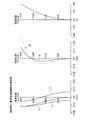
図1は、実施例1にかかるインナーフォーカス式レンズの構成を示す光軸に沿う断面図である。このインナーフォーカス式レンズは、図示しない物体側から順に、正の屈折力を有する第1レンズ群G11と、負の屈折力を有する第2レンズ群G12と、正の屈折力を有する第3レンズ群G13と、が配置されて構成される。また、第3レンズ群G13と結像面IMGとの間には、カバーガラスCGが配置されている。カバーガラスCGは必要に応じて配置されるものであり、不要な場合は省略可能である。なお、結像面IMGには、CCDやCMOSなどの撮像素子の受光面が配置される。 FIG. 1 is a cross-sectional view along the optical axis showing the configuration of the inner focus lens according to the first embodiment. The inner focus type lens includes a first lens group G 11 having a positive refractive power, a second lens group G 12 having a negative refractive power, and a third lens having a positive refractive power in order from an object side (not shown). a lens group G 13, is formed is disposed. Between the third lens group G 13 and the image plane IMG, a cover glass CG is disposed. The cover glass CG is arranged as necessary, and can be omitted if unnecessary. Note that a light receiving surface of an image sensor such as a CCD or a CMOS is disposed on the imaging plane IMG.
第1レンズ群G11は、物体側から順に、正レンズL111と、正レンズL112と、負レンズL113と、負レンズL114と、所定の口径を規定する開口絞りSTPと、負レンズL115と、正レンズL116と、が配置されて構成される。負レンズL115と正レンズL116とは、接合されている。負レンズL114には防振レンズとしての機能をもたせている。すなわち、負レンズL114を光軸に対して略垂直な方向に移動(偏芯)させることによって、手ぶれなどによる光学系の振動時に生じる像ぶれの補正を行う。特に、負レンズL114の屈折力を小さくすることでその曲率も小さくなり、負レンズL114を薄く軽量にすることができる。また、防振レンズである負レンズL114よりも結像面IMG側に開口絞りSTPが配置されていることにより、後続するレンズの口径を小さくすることができる。第1レンズ群G11のレンズ構成は、開口絞りSTPに対し略対称性が保たれている。 The first lens group G 11 includes, in order from the object side, a positive lens L 111, a positive lens L 112, a negative lens L 113, a negative lens L 114, and the aperture stop STP defining a predetermined aperture, a negative lens L 115 and a positive lens L 116 are arranged. The negative lens L 115 and the positive lens L 116 are cemented. The negative lens L 114 has a function as an anti-vibration lens. That is, by moving (decentering) the negative lens L 114 in a direction substantially perpendicular to the optical axis, image blur caused by vibration of the optical system due to camera shake is corrected. In particular, the curvature by reducing the refractive power of the negative lens L 114 is also reduced, it is possible to thin and light the negative lens L 114. Further, since the aperture stop STP is disposed on the image plane IMG side with respect to the negative lens L 114 which is an anti-vibration lens, the aperture of the subsequent lens can be reduced. Lens configuration of the first lens group G 11 is approximately symmetry is maintained to the aperture stop STP.
第2レンズ群G12は、負レンズL121により構成されている。第2レンズ群G12は、光軸に沿って物体側から結像面IMG側へ移動することにより、無限遠物体合焦状態から最至近距離物体合焦状態までのフォーカシングを行う。 The second lens group G 12 includes, is composed of a negative lens L 121. The second lens group G 12 includes, by moving from the object side along the optical axis to the image plane IMG side to perform focusing from infinity in-focus state to a closest distance object in-focus state.
第3レンズ群G13は、物体側から順に、正レンズL131と、負レンズL132と、が配置されて構成される。 The third lens group G 13 includes, in order from the object side, a positive lens L 131, a negative lens L 132, is formed are disposed.
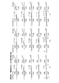
以下、実施例1にかかるインナーフォーカス式レンズに関する各種数値データを示す。 Various numerical data related to the inner focus lens according to Example 1 will be described below.
(レンズデータ)
r1=56.3969
d1=6.2609 nd1=1.83481 νd1=42.72
r2=-227.646
d2=0.4
r3=22.2275
d3=4.5373 nd2=1.83481 νd2=42.72
r4=61.9644
d4=0.8239
r5=213.9013
d5=0.9 nd3=1.72825 νd3=28.32
r6=15.7669
d6=6.2945
r7=-108.362
d7=0.8 nd4=1.72825 νd4=28.32
r8=84.2155
d8=4.4348
r9=∞(開口絞り)
d9=1.5
r10=32.8654
d10=0.8 nd5=1.84666 νd5=23.78
r11=18.5472
d11=4.5781 nd6=1.91082 νd6=35.25
r12=-110.767
d12=D(12)(可変)
r13=-228.318
d13=0.7 nd7=1.603 νd7=65.44
r14=18.6759
d14=D(14)(可変)
r15=39.4179
d15=7 nd8=1.72916 νd8=54.67
r16=-29.8753
d16=4.6748
r17=-25.5175
d17=1.8 nd9=1.80809 νd9=22.76
r18=-61.8081
d18=5
r19=∞
d19=2 nd10=1.5168 νd10=64.2
r20=∞
d20=9.8561
r21=∞(結像面)
(Lens data)
r 1 = 56.3969
d 1 = 6.2609 nd 1 = 1.83481 νd 1 = 42.72
r 2 = -227.646
d 2 = 0.4
r 3 = 22.2275
d 3 = 4.5373 nd 2 = 1.83481 νd 2 = 42.72
r 4 = 61.9644
d 4 = 0.8239
r 5 = 213.9013
d 5 = 0.9 nd 3 = 1.72825 νd 3 = 28.32
r 6 = 15.7669
d 6 = 6.2945
r 7 = -108.362
d 7 = 0.8 nd 4 = 1.772825 νd 4 = 28.32
r 8 = 84.2155
d 8 = 4.4348
r 9 = ∞ (aperture stop)
d 9 = 1.5
r 10 = 32.8654
d 10 = 0.8 nd 5 = 1.84666 νd 5 = 23.78
r 11 = 18.5472
d 11 = 4.5781 nd 6 = 1.91082 νd 6 = 35.25
r 12 = -110.767
d 12 = D (12) (variable)
r 13 = -228.318
d 13 = 0.7 nd 7 = 1.603 νd 7 = 65.44
r 14 = 18.6759
d 14 = D (14) (variable)
r 15 = 39.4179
d 15 = 7 nd 8 = 1.72916 νd 8 = 54.67
r 16 = -29.8753
d 16 = 4.6748
r 17 = -25.5175
d 17 = 1.8 nd 9 = 1.80809 νd 9 = 22.76
r 18 = -61.8081
d 18 = 5
r 19 = ∞
d 19 = 2 nd 10 = 1.5168 νd 10 = 64.2
r 20 = ∞
d 20 = 9.8561
r 21 = ∞ (imaging plane)
(各合焦状態の数値データ)
無限遠 0.025倍 最至近距離(0.141倍)
D(12) 1.804 2.598 6.351
D(14) 10.836 10.042 6.289
像高(Y) 14.20 14.20 14.20
(Numeric data for each in-focus state)
Infinity 0.025 times Closest distance (0.141 times)
D (12) 1.804 2.598 6.351
D (14) 10.836 10.042 6.289
Image height (Y) 14.20 14.20 14.20
f(光学系全系の焦点距離)=51.50
Fno=1.84
ω(半画角)=15.42
βvr(負レンズL114(防振レンズ)の結像倍率)=41.20
βr(第2レンズ群G12と第3レンズ群G13との合成結像倍率)=0.01
fvr(負レンズL114(防振レンズ)の焦点距離)=-64.96
f3(第3レンズ群G13の焦点距離)=36.75
f (focal length of the entire optical system) = 51.50
Fno = 1.84
ω (half angle of view) = 15.42
βvr (imaging magnification of negative lens L 114 (anti-vibration lens)) = 41.20
.beta.r (Synthesis imaging magnification of the second lens group G 12 and the third lens group G 13) = 0.01
fvr (focal length of negative lens L 114 (anti-vibration lens)) = − 64.96
f3 (the focal length of the third lens group G 13) = 36.75
(条件式(1)に関する数値)
|f/((1−βvr)×βr)|=95.49
(Numerical values related to conditional expression (1))
| F / ((1-βvr) × βr) | = 95.49
(条件式(2)に関する数値)
|fvr|/f=1.26
(Numerical value related to conditional expression (2))
| Fvr | /f=1.26
(条件式(3)に関する数値)
|f3|/f=0.71
(Numerical values related to conditional expression (3))
| F3 | /f=0.71
図2は、実施例1にかかるインナーフォーカス式レンズの無限遠物体合焦状態における縦収差図である。図3は、実施例1にかかるインナーフォーカス式レンズの撮影倍率0.025倍合焦状態における縦収差図である。図4は、実施例1にかかるインナーフォーカス式レンズの最至近距離物体合焦状態における縦収差図である。図中、gはg線(λ=435.83nm)、dはd線(λ=587.56nm)、CはC線(λ=656.28nm)に相当する波長の収差を表す。そして、非点収差図におけるS,Mは、それぞれサジタル像面、メリディオナル像面に対する収差を表す。 FIG. 2 is a longitudinal aberration diagram of the inner focus lens according to Example 1 when the object at infinity is in focus. FIG. 3 is a longitudinal aberration diagram of the inner focus lens according to Example 1 when the photographing magnification is 0.025. FIG. 4 is a longitudinal aberration diagram of the inner focus lens according to Example 1 in a state where an object at the closest distance is in focus. In the figure, g represents the g-line (λ = 435.83 nm), d represents the d-line (λ = 587.56 nm), and C represents the aberration of the wavelength corresponding to the C-line (λ = 656.28 nm). S and M in the astigmatism diagram represent aberrations with respect to the sagittal image surface and the meridional image surface, respectively.
また、図5は、実施例1にかかるインナーフォーカス式レンズの無限遠物体合焦状態における横収差図である。図6は、実施例1にかかるインナーフォーカス式レンズの撮影倍率0.025倍合焦状態における横収差図である。図7は、実施例1にかかるインナーフォーカス式レンズの最至近距離物体合焦状態における横収差図である。これらの図において、(a)は非防振補正時における実像高(Y’)0.0mmから14.2mmの横収差曲線、(b)は防振補正時において負レンズL114(防振レンズ)を光軸に対して垂直上方向へ0.50mm移動させ、結像位置を画角0.3度相当移動させた場合の実像高(Y’)0.0mmから14.2mmの横収差曲線、(c)は防振補正時において負レンズL114(防振レンズ)を光軸に対して垂直下方向へ−0.50mm移動させ、結像位置を画角−0.3度相当移動させた場合の実像高(Y’)0.0mmから−14.2mmの横収差曲線を示している。なお、gはg線(λ=435.83nm)、dはd線(λ=587.56nm)、CはC線(λ=656.28nm)に相当する波長の収差を表す。 FIG. 5 is a lateral aberration diagram of the inner focus lens according to Example 1 when the object at infinity is in focus. FIG. 6 is a lateral aberration diagram of the inner focus lens according to Example 1 when the photographing magnification is 0.025. FIG. 7 is a lateral aberration diagram of the inner focus lens according to Example 1 when the closest object is in focus. In these drawings, (a) is a lateral aberration curve from 0.0 mm to 14.2 mm in real image height (Y ′) at the time of non-shake correction, and (b) is a negative lens L 114 (anti-shake lens) at the time of shake correction. ) Is moved 0.50 mm vertically upward with respect to the optical axis, and the image formation position is moved by an angle corresponding to 0.3 °, the transverse aberration curve from 0.0 mm to 14.2 mm in real image height (Y ′). , (C) moves the negative lens L 114 (anti-vibration lens) by −0.50 mm vertically downward with respect to the optical axis and moves the image formation position by an angle of view corresponding to −0.3 degrees at the time of image stabilization. In this case, the lateral aberration curve of the real image height (Y ′) from 0.0 mm to −14.2 mm is shown. Here, g represents g-line (λ = 435.83 nm), d represents d-line (λ = 587.56 nm), and C represents aberration at a wavelength corresponding to C-line (λ = 656.28 nm).
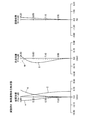
図8は、実施例2にかかるインナーフォーカス式レンズの構成を示す光軸に沿う断面図である。このインナーフォーカス式レンズは、図示しない物体側から順に、正の屈折力を有する第1レンズ群G21と、負の屈折力を有する第2レンズ群G22と、正の屈折力を有する第3レンズ群G23と、が配置されて構成される。また、第3レンズ群G23と結像面IMGとの間には、カバーガラスCGが配置されている。カバーガラスCGは必要に応じて配置されるものであり、不要な場合は省略可能である。なお、結像面IMGには、CCDやCMOSなどの撮像素子の受光面が配置される。 FIG. 8 is a cross-sectional view along the optical axis showing the configuration of the inner focus lens according to the second embodiment. The inner focus type lens includes a first lens group G 21 having a positive refractive power, a second lens group G 22 having a negative refractive power, and a third lens having a positive refractive power in order from an object side (not shown). a lens group G 23, is formed are disposed. Between the third lens group G 23 and the image plane IMG, a cover glass CG is disposed. The cover glass CG is arranged as necessary, and can be omitted if unnecessary. Note that a light receiving surface of an image sensor such as a CCD or a CMOS is disposed on the imaging plane IMG.
第1レンズ群G21は、物体側から順に、正レンズL211と、正レンズL212と、負レンズL213と、負レンズL214と、所定の口径を規定する開口絞りSTPと、負レンズL215と、正レンズL216と、が配置されて構成される。負レンズL215と正レンズL216とは、接合されている。負レンズL214には防振レンズとしての機能をもたせている。すなわち、負レンズL214を光軸に対して略垂直な方向に移動(偏芯)させることによって、手ぶれなどによる光学系の振動時に生じる像ぶれの補正を行う。特に、負レンズL214の屈折力を小さくすることでその曲率も小さくなり、負レンズL214を薄く軽量にすることができる。また、防振レンズである負レンズL214よりも結像面IMG側に開口絞りSTPが配置されていることにより、後続するレンズの口径を小さくすることができる。第1レンズ群G21のレンズ構成は、開口絞りSTPに対し略対称性が保たれている。 The first lens group G 21 includes, in order from the object side, a positive lens L 211 , a positive lens L 212 , a negative lens L 213 , a negative lens L 214 , an aperture stop STP that defines a predetermined aperture, and a negative lens An L 215 and a positive lens L 216 are arranged. The negative lens L 215 and the positive lens L 216 are cemented. The negative lens L 214 has a function as an anti-vibration lens. That is, by moving (decentering) the negative lens L 214 in a direction substantially perpendicular to the optical axis, correction of image blur that occurs during vibration of the optical system due to camera shake or the like is performed. In particular, the curvature by reducing the refractive power of the negative lens L 214 is also reduced, it is possible to thin and light the negative lens L 214. Further, since the aperture stop STP is disposed on the image plane IMG side with respect to the negative lens L 214 that is an anti-vibration lens, the aperture of the subsequent lens can be reduced. The lens configuration of the first lens group G 21 is substantially symmetric with respect to the aperture stop STP.
第2レンズ群G22は、負レンズL221により構成されている。第2レンズ群G22は、光軸に沿って物体側から結像面IMG側へ移動することにより、無限遠物体合焦状態から最至近距離物体合焦状態までのフォーカシングを行う。 The second lens group G 22 includes, is composed of a negative lens L 221. The second lens group G 22 includes, by moving from the object side along the optical axis to the image plane IMG side to perform focusing from infinity in-focus state to a closest distance object in-focus state.
第3レンズ群G23は、物体側から順に、正レンズL231と、負レンズL232と、が配置されて構成される。 The third lens group G 23 includes, in order from the object side, a positive lens L 231, a negative lens L 232, is formed are disposed.
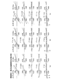
以下、実施例2にかかるインナーフォーカス式レンズに関する各種数値データを示す。 Various numerical data related to the inner focus lens according to Example 2 will be described below.
(レンズデータ)
r1=44.8799
d1=4.8446 nd1=1.83481 νd1=42.72
r2=-275.016
d2=0.4
r3=23.3824
d3=3.6557 nd2=1.91082 νd2=35.25
r4=55.6626
d4=1.0221
r5=263.1267
d5=0.9 nd3=1.72825 νd3=28.32
r6=15.5392
d6=6.1331
r7=-140.202
d7=0.8 nd4=1.8061 νd4=33.27
r8=67.9694
d8=4.575
r9=∞(開口絞り)
d9=1.5
r10=30.4655
d10=0.7 nd5=1.84666 νd5=23.78
r11=18.0217
d11=4.7707 nd6=1.83481 νd6=42.72
r12=-80.3201
d12=D(12)(可変)
r13=-142.554
d13=0.7 nd7=1.62041 νd7=60.34
r14=20.3958
d14=D(14)(可変)
r15=46.8341
d15=6.215 nd8=1.72916 νd8=54.67
r16=-33.8583
d16=7.8104
r17=-25.3869
d17=2 nd9=1.80518 νd9=25.46
r18=-38.0301
d18=5
r19=∞
d19=2 nd10=1.5168 νd10=64.2
r20=∞
d20=9.15
r21=∞(結像面)
(Lens data)
r 1 = 44.8799
d 1 = 4.8446 nd 1 = 1.83481 νd 1 = 42.72
r 2 = -275.016
d 2 = 0.4
r 3 = 23.3824
d 3 = 3.6557 nd 2 = 1.91082 νd 2 = 35.25
r 4 = 55.6626
d 4 = 1.0221
r 5 = 263.1267
d 5 = 0.9 nd 3 = 1.72825 νd 3 = 28.32
r 6 = 15.5392
d 6 = 6.1331
r 7 = -140.202
d 7 = 0.8 nd 4 = 1.8061 νd 4 = 33.27
r 8 = 67.9694
d 8 = 4.575
r 9 = ∞ (aperture stop)
d 9 = 1.5
r 10 = 30.4655
d 10 = 0.7 nd 5 = 1.84666 νd 5 = 23.78
r 11 = 18.0217
d 11 = 4.7707 nd 6 = 1.83481 νd 6 = 42.72
r 12 = -80.3201
d 12 = D (12) (variable)
r 13 = -142.554
d 13 = 0.7 nd 7 = 1.62041 νd 7 = 60.34
r 14 = 20.3958
d 14 = D (14) (variable)
r 15 = 46.8341
d 15 = 6.215 nd 8 = 1.72916 νd 8 = 54.67
r 16 = -33.8583
d 16 = 7.8104
r 17 = -25.3869
d 17 = 2 nd 9 = 1.80518 νd 9 = 25.46
r 18 = -38.0301
d 18 = 5
r 19 = ∞
d 19 = 2 nd 10 = 1.5168 νd 10 = 64.2
r 20 = ∞
d 20 = 9.15
r 21 = ∞ (imaging plane)
(各合焦状態の数値データ)
無限遠 0.025倍 最至近距離(0.142倍)
D(12) 1.796 2.630 6.599
D(14) 11.829 10.994 7.027
像高(Y) 14.20 14.20 14.20
(Numeric data for each in-focus state)
Infinity 0.025 times Closest distance (0.142 times)
D (12) 1.796 2.630 6.599
D (14) 11.829 10.994 7.027
Image height (Y) 14.20 14.20 14.20
f(光学系全系の焦点距離)=51.30
Fno=1.85
ω(半画角)=15.43
βvr(負レンズL214(防振レンズ)の結像倍率)=-10.46
βr(第2レンズ群G22と第3レンズ群G23との合成結像倍率)=-0.05
fvr(負レンズL214(防振レンズ)の焦点距離)=-56.69
f3(第3レンズ群G23の焦点距離)=35.02
f (focal length of the entire optical system) = 51.30
Fno = 1.85
ω (half angle of view) = 15.43
βvr (imaging magnification of negative lens L 214 (anti-vibration lens)) = − 10.46
βr (combined imaging magnification of the second lens group G 22 and the third lens group G 23 ) = − 0.05
fvr (focal length of negative lens L 214 (anti-vibration lens)) = − 56.69
f3 (the focal length of the third lens group G 23) = 35.02
(条件式(1)に関する数値)
|f/((1−βvr)×βr)|=82.21
(Numerical values related to conditional expression (1))
| F / ((1-βvr) × βr) | = 82.21
(条件式(2)に関する数値)
|fvr|/f=1.11
(Numerical value related to conditional expression (2))
| Fvr | /f=1.11
(条件式(3)に関する数値)
|f3|/f=0.68
(Numerical values related to conditional expression (3))
| F3 | /f=0.68
図9は、実施例2にかかるインナーフォーカス式レンズの無限遠物体合焦状態における縦収差図である。図10は、実施例2にかかるインナーフォーカス式レンズの撮影倍率0.025倍合焦状態における縦収差図である。図11は、実施例2にかかるインナーフォーカス式レンズの最至近距離物体合焦状態における縦収差図である。図中、gはg線(λ=435.83nm)、dはd線(λ=587.56nm)、CはC線(λ=656.28nm)に相当する波長の収差を表す。そして、非点収差図におけるS,Mは、それぞれサジタル像面、メリディオナル像面に対する収差を表す。 FIG. 9 is a longitudinal aberration diagram of the inner focus lens according to Example 2 when the object at infinity is in focus. FIG. 10 is a longitudinal aberration diagram of the inner focus lens according to Example 2 when the photographing magnification is 0.025. FIG. 11 is a longitudinal aberration diagram of the inner focus lens according to Example 2 when the closest object is in focus. In the figure, g represents the g-line (λ = 435.83 nm), d represents the d-line (λ = 587.56 nm), and C represents the aberration of the wavelength corresponding to the C-line (λ = 656.28 nm). S and M in the astigmatism diagram represent aberrations with respect to the sagittal image surface and the meridional image surface, respectively.
また、図12は、実施例2にかかるインナーフォーカス式レンズの無限遠物体合焦状態における横収差図である。図13は、実施例2にかかるインナーフォーカス式レンズの撮影倍率0.025倍合焦状態における横収差図である。図14は、実施例2にかかるインナーフォーカス式レンズの最至近距離物体合焦状態における横収差図である。これらの図において、(a)は非防振補正時における実像高(Y’)0.0mmから14.2mmの横収差曲線、(b)は防振補正時において負レンズL214(防振レンズ)を光軸に対して垂直上方向へ0.43mm移動させ、結像位置を画角0.3度相当移動させた場合の実像高(Y’)0.0mmから14.2mmの横収差曲線、(c)は防振補正時において負レンズL214(防振レンズ)を光軸に対して垂直下方向へ−0.43mm移動させ、結像位置を画角−0.3度相当移動させた場合の実像高(Y’)0.0mmから−14.2mmの横収差曲線を示している。なお、gはg線(λ=435.83nm)、dはd線(λ=587.56nm)、CはC線(λ=656.28nm)に相当する波長の収差を表す。 FIG. 12 is a lateral aberration diagram of the inner focus lens according to Example 2 when the object at infinity is in focus. FIG. 13 is a transverse aberration diagram for the inner focus lens according to Example 2 with the shooting magnification in the focusing state of 0.025. FIG. 14 is a lateral aberration diagram of the inner focus lens according to Example 2 when the closest object is in focus. In these drawings, (a) is a lateral aberration curve from 0.0 mm to 14.2 mm in real image height (Y ′) at the time of non-shake correction, and (b) is a negative lens L 214 (anti-shake lens) at the time of shake correction. ) Is moved 0.43 mm vertically upward with respect to the optical axis, and the image formation position is moved by an angle corresponding to an angle of view of 0.3 degrees, the actual image height (Y ′) is a lateral aberration curve from 0.0 mm to 14.2 mm. , (C) moves the negative lens L 214 (anti-vibration lens) by −0.43 mm vertically downward with respect to the optical axis at the time of image stabilization, and moves the image formation position by an angle of view equivalent to −0.3 degrees. In this case, the lateral aberration curve of the real image height (Y ′) from 0.0 mm to −14.2 mm is shown. Here, g represents g-line (λ = 435.83 nm), d represents d-line (λ = 587.56 nm), and C represents aberration at a wavelength corresponding to C-line (λ = 656.28 nm).
図15は、実施例3にかかるインナーフォーカス式レンズの構成を示す光軸に沿う断面図である。このインナーフォーカス式レンズは、図示しない物体側から順に、正の屈折力を有する第1レンズ群G31と、負の屈折力を有する第2レンズ群G32と、正の屈折力を有する第3レンズ群G33と、が配置されて構成される。また、第3レンズ群G33と結像面IMGとの間には、カバーガラスCGが配置されている。カバーガラスCGは必要に応じて配置されるものであり、不要な場合は省略可能である。なお、結像面IMGには、CCDやCMOSなどの撮像素子の受光面が配置される。 FIG. 15 is a cross-sectional view along the optical axis showing the configuration of the inner focus lens according to the third example. The inner focus type lens includes a first lens group G 31 having a positive refractive power, a second lens group G 32 having a negative refractive power, and a third lens having a positive refractive power in order from an object side (not shown). a lens group G 33, is formed are disposed. Further, a cover glass CG is disposed between the third lens group G 33 and the imaging plane IMG. The cover glass CG is arranged as necessary, and can be omitted if unnecessary. Note that a light receiving surface of an image sensor such as a CCD or a CMOS is disposed on the imaging plane IMG.
第1レンズ群G31は、物体側から順に、正レンズL311と、正レンズL312と、負レンズL313と、負レンズL314と、所定の口径を規定する開口絞りSTPと、負レンズL315と、正レンズL316と、が配置されて構成される。負レンズL315と正レンズL316とは、接合されている。負レンズL314には防振レンズとしての機能をもたせている。すなわち、負レンズL314を光軸に対して略垂直な方向に移動(偏芯)させることによって、手ぶれなどによる光学系の振動時に生じる像ぶれの補正を行う。特に、負レンズL314の屈折力を小さくすることでその曲率も小さくなり、負レンズL314を薄く軽量にすることができる。また、防振レンズである負レンズL314よりも結像面IMG側に開口絞りSTPが配置されていることにより、後続するレンズの口径を小さくすることができる。第1レンズ群G31のレンズ構成は、開口絞りSTPに対し略対称性が保たれている。 The first lens group G 31 includes, in order from the object side, a positive lens L 311 , a positive lens L 312 , a negative lens L 313 , a negative lens L 314 , an aperture stop STP that defines a predetermined aperture, and a negative lens An L 315 and a positive lens L 316 are arranged. The negative lens L 315 and the positive lens L 316 are cemented. The negative lens L 314 has a function as an anti-vibration lens. That is, by moving (decentering) the negative lens L 314 in a direction substantially perpendicular to the optical axis, image blur caused by vibration of the optical system due to camera shake or the like is corrected. In particular, by reducing the refractive power of the negative lens L 314 , its curvature is also reduced, and the negative lens L 314 can be made thin and light. Further, since the aperture stop STP is arranged on the image plane IMG side with respect to the negative lens L 314 which is an anti-vibration lens, the aperture of the subsequent lens can be reduced. The lens configuration of the first lens group G 31 is substantially symmetric with respect to the aperture stop STP.
第2レンズ群G32は、負レンズL321により構成されている。第2レンズ群G32は、光軸に沿って物体側から結像面IMG側へ移動することにより、無限遠物体合焦状態から最至近距離物体合焦状態までのフォーカシングを行う。 The second lens group G 32 is constituted by a negative lens L 321. The second lens group G 32 is, by moving from the object side along the optical axis to the image plane IMG side to perform focusing from infinity in-focus state to a closest distance object in-focus state.
第3レンズ群G33は、物体側から順に、正レンズL331と、負レンズL332と、が配置されて構成される。 The third lens group G 33 includes, in order from the object side, a positive lens L 331, a negative lens L 332, is formed are disposed.
以下、実施例3にかかるインナーフォーカス式レンズに関する各種数値データを示す。 Various numerical data relating to the inner focus lens according to Example 3 will be described below.
(レンズデータ)
r1=51.1089
d1=4.4589 nd1=1.83481 νd1=42.72
r2=860.7509
d2=0.4
r3=20.422
d3=4.864 nd2=1.83481 νd2=42.72
r4=55.2644
d4=0.3361
r5=66.8698
d5=0.9 nd3=1.72825 νd3=28.32
r6=14.8274
d6=6.8027
r7=-970.474
d7=0.8 nd4=1.72825 νd4=28.32
r8=49.3221
d8=4.5853
r9=∞(開口絞り)
d9=1.5
r10=28.105
d10=0.8 nd5=1.84666 νd5=23.78
r11=17.0221
d11=3.9726 nd6=1.91082 νd6=35.25
r12=454.2894
d12=D(12)(可変)
r13=-79.8991
d13=0.7 nd7=1.603 νd7=65.44
r14=19.9883
d14=D(14)(可変)
r15=43.4828
d15=7 nd8=1.72916 νd8=54.67
r16=-25.6466
d16=2.5
r17=-21.9075
d17=0.958 nd9=1.80809 νd9=22.76
r18=-35.5597
d18=5
r19=∞
d19=2 nd10=1.5168 νd10=64.2
r20=∞
d20=13.6221
r21=∞(結像面)
(Lens data)
r 1 = 51.1089
d 1 = 4.4589 nd 1 = 1.83481 νd 1 = 42.72
r 2 = 860.7509
d 2 = 0.4
r 3 = 20.422
d 3 = 4.864 nd 2 = 1.83481 νd 2 = 42.72
r 4 = 55.2644
d 4 = 0.3361
r 5 = 66.8698
d 5 = 0.9 nd 3 = 1.72825 νd 3 = 28.32
r 6 = 14.8274
d 6 = 6.8027
r 7 = -970.474
d 7 = 0.8 nd 4 = 1.772825 νd 4 = 28.32
r 8 = 49.3221
d 8 = 4.5853
r 9 = ∞ (aperture stop)
d 9 = 1.5
r 10 = 28.105
d 10 = 0.8 nd 5 = 1.84666 νd 5 = 23.78
r 11 = 17.0221
d 11 = 3.9726 nd 6 = 1.91082 νd 6 = 35.25
r 12 = 454.2894
d 12 = D (12) (variable)
r 13 = -79.8991
d 13 = 0.7 nd 7 = 1.603 νd 7 = 65.44
r 14 = 19.9883
d 14 = D (14) (variable)
r 15 = 43.4828
d 15 = 7 nd 8 = 1.72916 νd 8 = 54.67
r 16 = -25.6466
d 16 = 2.5
r 17 = -21.9075
d 17 = 0.958 nd 9 = 1.80809 νd 9 = 22.76
r 18 = -35.5597
d 18 = 5
r 19 = ∞
d 19 = 2 nd 10 = 1.5168 νd 10 = 64.2
r 20 = ∞
d 20 = 13.6221
r 21 = ∞ (imaging plane)
(各合焦状態の数値データ)
無限遠 0.025倍 最至近距離(0.142倍)
D(12) 2.418 3.258 7.488
D(14) 11.384 10.545 6.315
像高(Y) 14.20 14.20 14.20
(Numeric data for each in-focus state)
Infinity 0.025 times Closest distance (0.142 times)
D (12) 2.418 3.258 7.488
D (14) 11.384 10.545 6.315
Image height (Y) 14.20 14.20 14.20
f(光学系全系の焦点距離)=53.00
Fno=1.87
ω(半画角)=15.12
βvr(負レンズL314(防振レンズ)の結像倍率)=5.05
βr(第2レンズ群G32と第3レンズ群G33との合成結像倍率)=0.14
fvr(負レンズL314(防振レンズ)の焦点距離)=-64.43
f3(第3レンズ群G33の焦点距離)=31.80
f (focal length of the entire optical system) = 53.00
Fno = 1.87
ω (half angle of view) = 15.12
βvr (imaging magnification of negative lens L 314 (anti-vibration lens)) = 5.05
βr (combined imaging magnification of the second lens group G 32 and the third lens group G 33 ) = 0.14
fvr (focal length of negative lens L 314 (anti-vibration lens)) = − 64.43
f3 (the focal length of the third lens group G 33) = 31.80
(条件式(1)に関する数値)
|f/((1−βvr)×βr)|=95.49
(Numerical values related to conditional expression (1))
| F / ((1-βvr) × βr) | = 95.49
(条件式(2)に関する数値)
|fvr|/f=1.22
(Numerical value related to conditional expression (2))
| Fvr | /f=1.22
(条件式(3)に関する数値)
|f3|/f=0.60
(Numerical values related to conditional expression (3))
| F3 | /f=0.60
図16は、実施例3にかかるインナーフォーカス式レンズの無限遠物体合焦状態における縦収差図である。図17は、実施例3にかかるインナーフォーカス式レンズの撮影倍率0.025倍合焦状態における縦収差図である。図18は、実施例3にかかるインナーフォーカス式レンズの最至近距離物体合焦状態における縦収差図である。図中、gはg線(λ=435.83nm)、dはd線(λ=587.56nm)、CはC線(λ=656.28nm)に相当する波長の収差を表す。そして、非点収差図におけるS,Mは、それぞれサジタル像面、メリディオナル像面に対する収差を表す。 FIG. 16 is a longitudinal aberration diagram of the inner focus lens according to Example 3 when the object at infinity is in focus. FIG. 17 is a longitudinal aberration diagram of the inner focus lens according to Example 3 when the photographing magnification is 0.025. FIG. 18 is a longitudinal aberration diagram of the inner focus lens according to Example 3 when the object at the closest distance is in focus. In the figure, g represents the g-line (λ = 435.83 nm), d represents the d-line (λ = 587.56 nm), and C represents the aberration of the wavelength corresponding to the C-line (λ = 656.28 nm). S and M in the astigmatism diagram represent aberrations with respect to the sagittal image surface and the meridional image surface, respectively.
また、図19は、実施例3にかかるインナーフォーカス式レンズの無限遠物体合焦状態における横収差図である。図20は、実施例3にかかるインナーフォーカス式レンズの撮影倍率0.025倍合焦状態における横収差図である。図21は、実施例3にかかるインナーフォーカス式レンズの最至近距離物体合焦状態における横収差図である。これらの図において、(a)は非防振補正時における実像高(Y’)0.0mmから14.2mmの横収差曲線、(b)は防振補正時において負レンズL314(防振レンズ)を光軸に対して垂直上方向へ0.50mm移動させ、結像位置を画角0.3度相当移動させた場合の実像高(Y’)0.0mmから14.2mmの横収差曲線、(c)は防振補正時において負レンズL314(防振レンズ)を光軸に対して垂直下方向へ−0.50mm移動させ、結像位置を画角−0.3度相当移動させた場合の実像高(Y’)0.0mmから−14.2mmの横収差曲線を示している。なお、gはg線(λ=435.83nm)、dはd線(λ=587.56nm)、CはC線(λ=656.28nm)に相当する波長の収差を表す。 FIG. 19 is a lateral aberration diagram of the inner focus lens according to Example 3 when the object at infinity is in focus. FIG. 20 is a lateral aberration diagram for the inner focus lens according to Example 3 with the shooting magnification in the focusing state of 0.025. FIG. 21 is a lateral aberration diagram of the inner focus lens according to Example 3 when the closest object focus is achieved. In these drawings, (a) is a lateral aberration curve from 0.0 mm to 14.2 mm in real image height (Y ′) at the time of non-shake correction, and (b) is a negative lens L 314 (anti-shake lens) at the time of shake correction. ) Is moved 0.50 mm vertically upward with respect to the optical axis, and the image formation position is moved by an angle corresponding to 0.3 °, the transverse aberration curve from 0.0 mm to 14.2 mm in real image height (Y ′). , (C) moves the negative lens L 314 (anti-vibration lens) by −0.50 mm vertically downward with respect to the optical axis at the time of image stabilization, and moves the imaging position by an angle of view equivalent to −0.3 degrees. In this case, the lateral aberration curve of the real image height (Y ′) from 0.0 mm to −14.2 mm is shown. Here, g represents g-line (λ = 435.83 nm), d represents d-line (λ = 587.56 nm), and C represents aberration at a wavelength corresponding to C-line (λ = 656.28 nm).
なお、上記各実施例中の数値データにおいて、r1,r2,・・・・は各レンズ、絞り面などの曲率半径、d1,d2,・・・・は各レンズ、絞りなどの肉厚またはそれらの面間隔、nd1,nd2,・・・・は各レンズのd線(λ=587.56nm)に対する屈折率、νd1,νd2,・・・・は各レンズのd線(λ=587.56nm)に対するアッベ数を示している。そして、長さの単位はすべて「mm」、角度の単位はすべて「°」である。 In the numerical data in each of the above embodiments, r 1 , r 2 ,... Are the curvature radii of the respective lenses and diaphragm surfaces, and d 1 , d 2 ,. thickness or their surface separations, nd 1, nd 2, the refractive index with respect to ... the d-line of each lens (λ = 587.56nm), νd 1 , νd 2, ···· are each lens d The Abbe number for the line (λ = 587.56 nm) is shown. The unit of length is all “mm”, and the unit of angle is “°”.
以上説明したように、上記各実施例のインナーフォーカス式レンズは、手ぶれなどによる光学系の振動時に生じる像ぶれの補正を行う防振レンズの軽量化と、防振補正時の防振レンズの移動量の抑制を図ることができる。また、開口絞りを第1レンズ群内の適切な位置に配置することにより、光学系の後玉径を小さくすることもできる。さらに、上記条件式を満足することで、より小型で高い結像性能を有するインナーフォーカス方式レンズを実現することができる。 As described above, the inner focus type lens in each of the above-described embodiments is a weight reduction of an image stabilization lens that corrects image blur caused by vibration of the optical system due to camera shake or the like, and movement of the image stabilization lens at the time of image stabilization correction. The amount can be reduced. Further, the rear lens diameter of the optical system can be reduced by arranging the aperture stop at an appropriate position in the first lens group. Furthermore, by satisfying the above conditional expression, an inner focus type lens having a smaller size and higher imaging performance can be realized.
以上のように、この発明にかかるインナーフォーカス式レンズは、写真用カメラ、ビデオカメラなどに有用であり、特に、振動を受けやすい場所で用いられる撮像装置に最適である。 As described above, the inner focus type lens according to the present invention is useful for a photographic camera, a video camera, and the like, and is particularly suitable for an imaging device used in a place where it is susceptible to vibration.
G11,G21,G31 第1レンズ群
G12,G22,G32 第2レンズ群
G13,G23,G33 第3レンズ群
L111,L112,L116,L131,L211,L212,L216,L231,L311,L312,L316,L331 正レンズ
L113,L114,L115,L121,L132,L213,L214,L215,L221,L232,L313,L314,L315,L321,L332 負レンズ
CG カバーガラス
IMG 結像面
STP 開口絞り
G 11, G 21, G 31 first lens group G 12, G 22, G 32 second lens group G 13, G 23, G 33 third lens group L 111, L 112, L 116 , L 131, L 211 , L212 , L216 , L231 , L311 , L312 , L316 , L331 positive lenses L113 , L114 , L115 , L121 , L132 , L213 , L214 , L215 , L221 , L 232 , L 313 , L 314 , L 315 , L 321 , L 332 Negative lens CG Cover glass IMG Imaging surface STP Aperture stop
Claims (4)
前記第1レンズ群を、光軸に対して略垂直方向へ移動させることによって光学系の振動時に生じる像ぶれの補正を行うための負レンズからなる防振レンズと、該防振レンズよりも像側に配置された開口絞りと、を含み構成し、
前記第2レンズ群を光軸に沿って移動させてフォーカシングを行うことを特徴とするインナーフォーカス式レンズ。 A first lens group having a positive refractive power, a second lens group having a negative refractive power, and a third lens group having a positive refractive power, which are arranged in order from the object side,
An anti-vibration lens composed of a negative lens for correcting image blur caused when the optical system vibrates by moving the first lens group in a direction substantially perpendicular to the optical axis, and an image more effective than the anti-vibration lens. Including an aperture stop disposed on the side,
An inner focus lens, wherein focusing is performed by moving the second lens group along an optical axis.
(1) 65.76<|f/((1−βvr)×βr)|<114.59
ただし、fは光学系全系の焦点距離、βvrは前記防振レンズの結像倍率、βrは前記防振レンズを含むレンズ群より像側に配置されているレンズ群の合成結像倍率を示す。 2. The inner focus lens according to claim 1, wherein the following conditional expression is satisfied.
(1) 65.76 <| f / ((1-βvr) × βr) | <114.59
Where f is the focal length of the entire optical system, βvr is the imaging magnification of the image stabilizing lens, and βr is the combined image forming magnification of the lens group arranged on the image side from the lens group including the image stabilizing lens. .
(2) 0.88<|fvr|/f<1.55
ただし、fvrは前記防振レンズの焦点距離、fは光学系全系の焦点距離を示す。 The inner focus lens according to claim 1, wherein the following conditional expression is satisfied.
(2) 0.88 <| fvr | / f <1.55
Here, fvr represents the focal length of the image stabilizing lens, and f represents the focal length of the entire optical system.
(3) 0.48<|f3|/f<0.86
ただし、f3は前記第3レンズ群の焦点距離、fは光学系全系の焦点距離を示す。 The inner focus type lens according to claim 1, wherein the following conditional expression is satisfied.
(3) 0.48 <| f3 | / f <0.86
Here, f3 represents the focal length of the third lens group, and f represents the focal length of the entire optical system.
Priority Applications (3)
| Application Number | Priority Date | Filing Date | Title |
|---|---|---|---|
| JP2011114189A JP2012242690A (en) | 2011-05-20 | 2011-05-20 | Inner focus type lens |
| CN201210119313.XA CN102789043B (en) | 2011-05-20 | 2012-04-20 | Internal focusing lens |
| US13/466,423 US9116286B2 (en) | 2011-05-20 | 2012-05-08 | Internal focus lens |
Applications Claiming Priority (1)
| Application Number | Priority Date | Filing Date | Title |
|---|---|---|---|
| JP2011114189A JP2012242690A (en) | 2011-05-20 | 2011-05-20 | Inner focus type lens |
Publications (1)
| Publication Number | Publication Date |
|---|---|
| JP2012242690A true JP2012242690A (en) | 2012-12-10 |
Family
ID=47154487
Family Applications (1)
| Application Number | Title | Priority Date | Filing Date |
|---|---|---|---|
| JP2011114189A Pending JP2012242690A (en) | 2011-05-20 | 2011-05-20 | Inner focus type lens |
Country Status (3)
| Country | Link |
|---|---|
| US (1) | US9116286B2 (en) |
| JP (1) | JP2012242690A (en) |
| CN (1) | CN102789043B (en) |
Cited By (10)
| Publication number | Priority date | Publication date | Assignee | Title |
|---|---|---|---|---|
| JP2013218266A (en) * | 2012-03-15 | 2013-10-24 | Panasonic Corp | Inner focus lens, interchangeable lens device, and camera system |
| JP2014089351A (en) * | 2012-10-30 | 2014-05-15 | Tamron Co Ltd | Inner focus lens |
| JP2014211499A (en) * | 2013-04-17 | 2014-11-13 | 株式会社ニコン | Photographic lens, optical equipment, and method for manufacturing photographic lens |
| WO2016036210A1 (en) * | 2014-09-05 | 2016-03-10 | Samsung Electronics Co., Ltd. | Inner foucing telephoto lens system and photographing apparatus including the same |
| CN105785689A (en) * | 2015-01-08 | 2016-07-20 | 株式会社腾龙 | Optical system and image pickup apparatus |
| US9671594B2 (en) | 2015-07-10 | 2017-06-06 | Fujifilm Corporation | Imaging lens and imaging apparatus |
| US10073255B2 (en) | 2016-08-01 | 2018-09-11 | Olympus Corporation | Single focal length lens and optical apparatus using the same |
| US10139600B2 (en) | 2016-10-06 | 2018-11-27 | Fujifilm Corporation | Imaging lens and imaging apparatus |
| US10168507B2 (en) | 2016-10-04 | 2019-01-01 | Fujifilm Corporation | Imaging lens and imaging apparatus |
| US10274704B2 (en) | 2016-10-06 | 2019-04-30 | Fujifilm Corporation | Imaging lens and imaging apparatus |
Families Citing this family (4)
| Publication number | Priority date | Publication date | Assignee | Title |
|---|---|---|---|---|
| JP6099966B2 (en) * | 2012-12-21 | 2017-03-22 | キヤノン株式会社 | Imaging optical system and imaging apparatus having the same |
| JP2015108811A (en) * | 2013-10-22 | 2015-06-11 | オリンパス株式会社 | Single focal length lens system and image capturing device having the same |
| JP6579997B2 (en) * | 2016-05-19 | 2019-09-25 | キヤノン株式会社 | Optical system and imaging apparatus having the same |
| JP7242411B2 (en) * | 2019-04-26 | 2023-03-20 | キヤノン株式会社 | Optical system and imaging device |
Citations (2)
| Publication number | Priority date | Publication date | Assignee | Title |
|---|---|---|---|---|
| JP2000284171A (en) * | 1999-04-01 | 2000-10-13 | Canon Inc | Photographic lens capable of short-distance photographing |
| WO2009096536A1 (en) * | 2008-01-30 | 2009-08-06 | Nikon Corporation | Variable magnification optical system, optical apparatus provided with the variable magnification optical system and method for manufacturing variable magnification optical system |
Family Cites Families (18)
| Publication number | Priority date | Publication date | Assignee | Title |
|---|---|---|---|---|
| US5040881A (en) * | 1988-05-12 | 1991-08-20 | Canon Kabushiki Kaisha | Image stabilization lens system |
| EP0592916B1 (en) * | 1992-10-14 | 1998-01-21 | Nikon Corporation | Zoom lens incorporating vibration-proofing function |
| JP3072815B2 (en) * | 1993-10-08 | 2000-08-07 | キヤノン株式会社 | Variable power optical system |
| JP3412964B2 (en) | 1995-05-10 | 2003-06-03 | キヤノン株式会社 | Optical system with anti-vibration function |
| JP3541283B2 (en) | 1995-05-26 | 2004-07-07 | 株式会社ニコン | Inner focus telephoto lens |
| US6081390A (en) * | 1997-08-07 | 2000-06-27 | Minolta Co., Ltd. | Zoom lens system having camera shake compensating function |
| US6115188A (en) | 1997-10-16 | 2000-09-05 | Canon Kabushiki Kaisha | Optical system and optical apparatus having the same |
| JP4272725B2 (en) | 1998-09-11 | 2009-06-03 | キヤノン株式会社 | Optical system |
| JP3524408B2 (en) * | 1998-01-06 | 2004-05-10 | キヤノン株式会社 | Observation optical system and optical apparatus having the same |
| US6493142B1 (en) * | 1999-07-30 | 2002-12-10 | Canon Kabushiki Kaisha | Zoom lens and photographing apparatus having it |
| JP4467920B2 (en) * | 2003-08-08 | 2010-05-26 | キヤノン株式会社 | Imaging lens and imaging apparatus having the same |
| US7583441B2 (en) * | 2004-07-09 | 2009-09-01 | Canon Kabushiki Kaisha | Photographic lens system and image pickup apparatus |
| JP4857576B2 (en) | 2005-03-23 | 2012-01-18 | 株式会社ニコン | Zoom lens |
| JP4655205B2 (en) * | 2005-05-26 | 2011-03-23 | ソニー株式会社 | Zoom lens and imaging device |
| JP4904837B2 (en) * | 2006-02-03 | 2012-03-28 | 株式会社ニコン | Zoom lens with anti-vibration function |
| US7965454B2 (en) * | 2008-08-28 | 2011-06-21 | Konica Minolta Opto, Inc. | Imaging lens and small-size image pickup apparatus using the same |
| JP5562552B2 (en) * | 2008-12-26 | 2014-07-30 | 株式会社シグマ | Inner focus type anti-vibration lens |
| JP5378880B2 (en) * | 2009-05-20 | 2013-12-25 | 株式会社シグマ | Inner focus type macro lens |
-
2011
- 2011-05-20 JP JP2011114189A patent/JP2012242690A/en active Pending
-
2012
- 2012-04-20 CN CN201210119313.XA patent/CN102789043B/en not_active Expired - Fee Related
- 2012-05-08 US US13/466,423 patent/US9116286B2/en active Active
Patent Citations (2)
| Publication number | Priority date | Publication date | Assignee | Title |
|---|---|---|---|---|
| JP2000284171A (en) * | 1999-04-01 | 2000-10-13 | Canon Inc | Photographic lens capable of short-distance photographing |
| WO2009096536A1 (en) * | 2008-01-30 | 2009-08-06 | Nikon Corporation | Variable magnification optical system, optical apparatus provided with the variable magnification optical system and method for manufacturing variable magnification optical system |
Cited By (11)
| Publication number | Priority date | Publication date | Assignee | Title |
|---|---|---|---|---|
| JP2013218266A (en) * | 2012-03-15 | 2013-10-24 | Panasonic Corp | Inner focus lens, interchangeable lens device, and camera system |
| JP2014089351A (en) * | 2012-10-30 | 2014-05-15 | Tamron Co Ltd | Inner focus lens |
| JP2014211499A (en) * | 2013-04-17 | 2014-11-13 | 株式会社ニコン | Photographic lens, optical equipment, and method for manufacturing photographic lens |
| WO2016036210A1 (en) * | 2014-09-05 | 2016-03-10 | Samsung Electronics Co., Ltd. | Inner foucing telephoto lens system and photographing apparatus including the same |
| CN105785689A (en) * | 2015-01-08 | 2016-07-20 | 株式会社腾龙 | Optical system and image pickup apparatus |
| CN105785689B (en) * | 2015-01-08 | 2020-04-10 | 株式会社腾龙 | Optical system and image pickup apparatus |
| US9671594B2 (en) | 2015-07-10 | 2017-06-06 | Fujifilm Corporation | Imaging lens and imaging apparatus |
| US10073255B2 (en) | 2016-08-01 | 2018-09-11 | Olympus Corporation | Single focal length lens and optical apparatus using the same |
| US10168507B2 (en) | 2016-10-04 | 2019-01-01 | Fujifilm Corporation | Imaging lens and imaging apparatus |
| US10139600B2 (en) | 2016-10-06 | 2018-11-27 | Fujifilm Corporation | Imaging lens and imaging apparatus |
| US10274704B2 (en) | 2016-10-06 | 2019-04-30 | Fujifilm Corporation | Imaging lens and imaging apparatus |
Also Published As
| Publication number | Publication date |
|---|---|
| CN102789043A (en) | 2012-11-21 |
| CN102789043B (en) | 2014-12-10 |
| US20120293869A1 (en) | 2012-11-22 |
| US9116286B2 (en) | 2015-08-25 |
Similar Documents
| Publication | Publication Date | Title |
|---|---|---|
| JP2012242690A (en) | Inner focus type lens | |
| JP5612515B2 (en) | Fixed focus lens | |
| JP5379784B2 (en) | Fixed focus lens | |
| JP5749629B2 (en) | Inner focus telephoto lens | |
| JP5475401B2 (en) | Large-aperture telephoto zoom lens with anti-vibration function | |
| JP5378880B2 (en) | Inner focus type macro lens | |
| JP6378083B2 (en) | Inner focus lens | |
| JP2009086535A (en) | Zoom lens and optical apparatus equipped with the same | |
| JP2012242689A (en) | Inner focus type lens | |
| JP2020187181A (en) | Imaging optical system and image capturing device | |
| JP2020016788A (en) | Image capturing lens and image capturing device | |
| JP5448574B2 (en) | Zoom lens and imaging apparatus having the same | |
| JP2012181525A (en) | Zoom lens | |
| JP5217832B2 (en) | Lens system and optical device | |
| JP2013178409A (en) | Zoom lens | |
| JP2006106112A (en) | Interchangeable lens | |
| JP2012242504A (en) | Inner focus type optical system | |
| JP2015096915A (en) | Inner focus lens and imaging apparatus | |
| JP2015102559A (en) | Large aperture lens with anti-shake capability | |
| JP5217694B2 (en) | Lens system and optical device | |
| JP5277625B2 (en) | Macro lens, optical device, macro lens focusing method, macro lens vibration isolation method | |
| JP2012173435A (en) | Fixed-focus lens | |
| JP2014089351A (en) | Inner focus lens | |
| JP5783375B2 (en) | Macro lens | |
| JP5848099B2 (en) | Inner focus type large aperture telephoto macro lens with anti-vibration function |
Legal Events
| Date | Code | Title | Description |
|---|---|---|---|
| A621 | Written request for application examination |
Free format text: JAPANESE INTERMEDIATE CODE: A621 Effective date: 20140107 |
|
| A977 | Report on retrieval |
Free format text: JAPANESE INTERMEDIATE CODE: A971007 Effective date: 20140618 |
|
| A131 | Notification of reasons for refusal |
Free format text: JAPANESE INTERMEDIATE CODE: A131 Effective date: 20140624 |
|
| A02 | Decision of refusal |
Free format text: JAPANESE INTERMEDIATE CODE: A02 Effective date: 20141028 |