JP2012241383A - Ground improvement method and decompression container - Google Patents
Ground improvement method and decompression container Download PDFInfo
- Publication number
- JP2012241383A JP2012241383A JP2011111145A JP2011111145A JP2012241383A JP 2012241383 A JP2012241383 A JP 2012241383A JP 2011111145 A JP2011111145 A JP 2011111145A JP 2011111145 A JP2011111145 A JP 2011111145A JP 2012241383 A JP2012241383 A JP 2012241383A
- Authority
- JP
- Japan
- Prior art keywords
- steel pipe
- ground
- lid
- decompression
- pipe
- Prior art date
- Legal status (The legal status is an assumption and is not a legal conclusion. Google has not performed a legal analysis and makes no representation as to the accuracy of the status listed.)
- Granted
Links
- 230000006837 decompression Effects 0.000 title claims abstract description 86
- 230000006872 improvement Effects 0.000 title claims abstract description 43
- 238000000034 method Methods 0.000 title claims abstract description 31
- 229910000831 Steel Inorganic materials 0.000 claims abstract description 104
- 239000010959 steel Substances 0.000 claims abstract description 104
- XLYOFNOQVPJJNP-UHFFFAOYSA-N water Substances O XLYOFNOQVPJJNP-UHFFFAOYSA-N 0.000 claims abstract description 28
- 238000009434 installation Methods 0.000 claims abstract description 10
- 239000002689 soil Substances 0.000 claims abstract description 6
- 238000012856 packing Methods 0.000 claims description 48
- 239000000463 material Substances 0.000 claims description 15
- 239000011148 porous material Substances 0.000 claims description 5
- 230000008569 process Effects 0.000 claims description 4
- 238000005086 pumping Methods 0.000 claims description 4
- 229910001208 Crucible steel Inorganic materials 0.000 claims 1
- 229920001971 elastomer Polymers 0.000 description 38
- 238000007596 consolidation process Methods 0.000 description 17
- 238000010276 construction Methods 0.000 description 8
- 230000035515 penetration Effects 0.000 description 7
- 230000009467 reduction Effects 0.000 description 7
- 238000003466 welding Methods 0.000 description 6
- 238000004519 manufacturing process Methods 0.000 description 5
- 239000004567 concrete Substances 0.000 description 4
- 230000002093 peripheral effect Effects 0.000 description 4
- 238000002474 experimental method Methods 0.000 description 3
- 239000003673 groundwater Substances 0.000 description 3
- 239000007788 liquid Substances 0.000 description 3
- 230000005514 two-phase flow Effects 0.000 description 3
- 230000009471 action Effects 0.000 description 2
- 238000005056 compaction Methods 0.000 description 2
- 230000006835 compression Effects 0.000 description 2
- 238000007906 compression Methods 0.000 description 2
- 230000006378 damage Effects 0.000 description 2
- 238000010586 diagram Methods 0.000 description 2
- 238000006073 displacement reaction Methods 0.000 description 2
- 230000000694 effects Effects 0.000 description 2
- 239000011178 precast concrete Substances 0.000 description 2
- 239000004576 sand Substances 0.000 description 2
- 239000012780 transparent material Substances 0.000 description 2
- 229920001875 Ebonite Polymers 0.000 description 1
- 230000008901 benefit Effects 0.000 description 1
- 230000015572 biosynthetic process Effects 0.000 description 1
- 238000005516 engineering process Methods 0.000 description 1
- 230000001771 impaired effect Effects 0.000 description 1
- 238000012423 maintenance Methods 0.000 description 1
- 238000012986 modification Methods 0.000 description 1
- 230000004048 modification Effects 0.000 description 1
- 230000036316 preload Effects 0.000 description 1
- 230000001737 promoting effect Effects 0.000 description 1
- 238000011160 research Methods 0.000 description 1
- 229910052710 silicon Inorganic materials 0.000 description 1
- 239000010703 silicon Substances 0.000 description 1
- 239000002002 slurry Substances 0.000 description 1
- 239000007787 solid Substances 0.000 description 1
- 238000010998 test method Methods 0.000 description 1
- 229920002725 thermoplastic elastomer Polymers 0.000 description 1
- 238000009834 vaporization Methods 0.000 description 1
- 230000008016 vaporization Effects 0.000 description 1
- 239000004636 vulcanized rubber Substances 0.000 description 1
Images


Abstract
Description
本発明は、真空圧密による地盤改良方法およびその地盤改良方法に使用可能な減圧容器に関する。 The present invention relates to a ground improvement method by vacuum consolidation and a decompression vessel usable for the ground improvement method.
吸引力を発生させて、水を吸引し排水する装置として真空ポンプを用いた吸引装置が知られている。従来の技術では、例えば、軟弱地盤内に鉛直ドレーンを打設した後、真空ポンプによる吸引装置を用いて、負圧を作用させて地盤内を減圧することによって、地盤の圧密を促進する方法が用いられている(例えば、特許文献1〜3)。また、特許文献4のように、減圧室に鉛直管を挿入し、鉛直管内で気液2相流を形成させてサイフォン機能を発揮させるようにした吸引力発生装置が本発明者の一人および他の発明者によって提案されている。 A suction device using a vacuum pump is known as a device that generates a suction force to suck and drain water. In the conventional technology, for example, after placing a vertical drain in soft ground, a method of promoting consolidation of the ground by applying a negative pressure to decompress the ground using a vacuum pump suction device. It is used (for example, Patent Documents 1 to 3). Further, as disclosed in Patent Document 4, a suction force generating device in which a vertical pipe is inserted into a decompression chamber and a gas-liquid two-phase flow is formed in the vertical pipe so as to exhibit a siphon function is disclosed by one of the present inventors and others. Proposed by the inventors.
陸上域の地盤を対象にして、特許文献4のように真空ポンプとサイフォンの吸引力を併用して吸引し排水を行う場合、サイフォンを機能させるためには、鉛直に長い排水管を持つ減圧容器が必要になる。陸上域の軟弱地盤改良を目的として減圧容器を導入する場合、減圧容器を地中に設置する必要があるため、減圧容器の製作や設置方法が問題となる。特に、現地で減圧容器を製作する場合、十分な強度と気密性を持つ容器を製作することが難しいことが多い。また、気密漏れや高負圧時における溶存気体の気化等、空気混入しがちな施工条件のため、サイフォンを安定して機能させることが必要である。 When suctioning and draining using the vacuum pump and siphon suction force together as in Patent Document 4 for the ground in the land area, in order to make the siphon function, a decompression container having a vertically long drain pipe Is required. When introducing a decompression vessel for the purpose of improving soft ground on land, it is necessary to install the decompression vessel in the ground, so the production and installation method of the decompression vessel becomes a problem. In particular, when manufacturing a decompression container locally, it is often difficult to manufacture a container having sufficient strength and airtightness. Moreover, it is necessary to make the siphon function stably because of construction conditions that tend to be mixed with air, such as airtight leakage and vaporization of dissolved gas at high negative pressure.
本発明は、上述のような従来技術の問題に鑑み、地盤改良対象域で製作可能であり十分な強度と気密性を有する減圧容器を設置可能な地盤改良方法および減圧容器を提供することを目的とする。 The present invention has been made in view of the above-mentioned problems of the prior art, and an object of the present invention is to provide a ground improvement method and a vacuum container that can be installed in a ground improvement target area and can be installed with a vacuum container having sufficient strength and airtightness. And
上記目的を達成するための地盤改良方法は、上部内面から突き出た環状部を有する鋼管を地中に打設する工程と、前記打設された鋼管内の土を排除する工程と、前記鋼管の底部側に底板を設置する工程と、前記鋼管内部に収納される揚水ポンプと連結する排水管と、真空ポンプと連結する吸気管と、サイフォンを機能させる鉛直管と、をそれぞれ貫通させた蓋体を前記鋼管の環状部に静置する工程と、により減圧容器を地中に完成させ、次に、前記真空ポンプの駆動による負圧で前記蓋体を前記鋼管の環状部に密着させ、前記真空ポンプによる吸引力と前記鉛直管のサイフォン機能による吸引力とを発揮させることで改良対象の地盤中の間隙水を、前記地盤に打設された鉛直ドレーン材を通して吸引し排水することを特徴とする。 A ground improvement method for achieving the above object includes a step of placing a steel pipe having an annular portion protruding from an upper inner surface into the ground, a step of removing soil in the placed steel pipe, A lid that penetrates a step of installing a bottom plate on the bottom side, a drain pipe connected to a pumping pump housed inside the steel pipe, an intake pipe connected to a vacuum pump, and a vertical pipe that functions a siphon, respectively. The vacuum vessel is completed in the ground by the step of standing in the annular part of the steel pipe, and then the lid is brought into close contact with the annular part of the steel pipe by the negative pressure generated by driving the vacuum pump. It is characterized in that the pore water in the ground to be improved is sucked and drained through the vertical drain material placed on the ground by exerting the suction force by the pump and the suction force by the siphon function of the vertical pipe. .
この地盤改良方法によれば、入手容易で強度のある鋼管を地盤に打設し、蓋体を鋼管の環状部に静置することで、減圧容器を容易に地中に完成させることができる。真空ポンプの駆動により蓋体を環状部に密着させて、ボルトや溶接等の取り付け固定手段を用いずに、減圧容器の気密性を確保できるとともに、サイフォンを機能させる鉛直管を収容する容器本体を鋼管から構成できるので、減圧容器を容易に地盤改良対象域で製作することができ、真空圧密による地盤改良を容易に実行できる。 According to this ground improvement method, a decompression container can be easily completed in the ground by placing an easily available and strong steel pipe on the ground and leaving the lid on the annular portion of the steel pipe. A container body that accommodates a vertical pipe that allows the siphon to function while ensuring the airtightness of the decompression container without using attachment fixing means such as bolts and welding by closely attaching the lid to the annular portion by driving the vacuum pump Since it can be composed of a steel pipe, the decompression vessel can be easily manufactured in the ground improvement target area, and the ground improvement by vacuum consolidation can be easily performed.
上記地盤改良方法において前記蓋体と前記環状部との間に弾性体からなる気密部材を配置することで、減圧容器の気密性を高めることができる。 In the ground improvement method, an airtight member made of an elastic body is disposed between the lid and the annular portion, whereby the airtightness of the decompression container can be enhanced.
また、前記鋼管の底板の位置と前記鋼管の下端位置との間の距離が前記鋼管の径の1/2以上となるようにすることで、減圧容器を軟弱地盤に設置した場合、減圧容器に上向きに作用する浮力が加わっても減圧容器の安定性を確保することができる。 Moreover, when the decompression container is installed on the soft ground by making the distance between the position of the bottom plate of the steel pipe and the lower end position of the steel pipe more than 1/2 of the diameter of the steel pipe, Even if buoyancy acting upward is applied, the stability of the decompression vessel can be secured.
上記目的を達成するための地盤改良方法は、減圧容器は、地中に設置され真空ポンプにより内部が減圧される減圧容器であって、容器本体として地中に打設される鋼管と、前記容器本体の底部側に設けられる底板と、前記容器本体を閉塞する蓋体と、を備え、前記蓋体が前記容器本体の被設置部に静置される構造を有し、前記真空ポンプの駆動による負圧で前記蓋体を前記被設置部に密着させることを特徴とする。 The ground improvement method for achieving the above object is that a decompression container is a decompression container that is installed in the ground and whose inside is decompressed by a vacuum pump, and a steel pipe that is placed in the ground as a container body, and the container A bottom plate provided on the bottom side of the main body, and a lid for closing the container main body, the lid body being configured to be stationary on an installation portion of the container main body, and by driving the vacuum pump The lid is brought into close contact with the portion to be installed with a negative pressure.
この減圧容器によれば、サイフォンを機能させる鉛直管を収容する容器本体を入手容易で強度がある鋼管から構成し、蓋体が容器本体の被設置部に静置される構造とし、真空ポンプの駆動により蓋体を被設置部に密着させるので、地盤改良対象域で製作可能であり十分な強度と気密性を有することができる。 According to this decompression container, the container main body that houses the vertical pipe for functioning the siphon is made of a steel pipe that is easily available and strong, and the lid body is placed on the installation part of the container main body. Since the lid is brought into close contact with the portion to be installed by driving, the lid can be manufactured in the ground improvement target area and can have sufficient strength and airtightness.
上記減圧容器において前記鋼管は、その上部内面から突き出るように設けられた環状部を有し、前記環状部を前記被設置部として前記蓋体が前記環状部に載置され、前記蓋体と前記環状部との間に弾性体からなる気密部材が配置されることが好ましい。これにより、簡単な構成で減圧容器の気密性を高めることができる。 In the decompression vessel, the steel pipe has an annular portion provided so as to protrude from an upper inner surface thereof, and the lid body is placed on the annular portion with the annular portion as the installation portion. It is preferable that an airtight member made of an elastic body is disposed between the annular portion. Thereby, the airtightness of the decompression container can be enhanced with a simple configuration.
また、前記気密部材は、高さの高い変形容易なパッキンと、高さの低い変形し難いパッキンとから構成されることで、減圧容器の気密性をさらに高めることができる。 Moreover, the airtight member can be further improved in airtightness of the decompression container by being composed of a high-height packing that is easy to deform and a low-height packing that is difficult to deform.
上述の地盤改良方法は、上述の減圧容器を地中に設置することで、実行することができる。 The above-described ground improvement method can be executed by installing the above-described decompression container in the ground.
本発明によれば、地盤改良対象域で製作可能であり十分な強度と気密性を有する減圧容器を設置可能な地盤改良方法および減圧容器を提供できる。 ADVANTAGE OF THE INVENTION According to this invention, the ground improvement method and pressure reduction container which can be manufactured in the ground improvement object area and can install the pressure reduction container which has sufficient intensity | strength and airtightness can be provided.
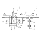
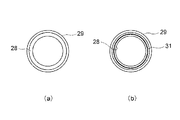
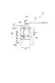
以下、本発明を実施するための形態について図面を用いて説明する。図1は本実施形態の真空圧密による地盤改良方法を実行可能な減圧容器を含む真空圧密地盤改良システムの構成を概略的に示す図である。図2は図1の減圧容器の鋼管を上部からみた上面図(a)および鋼管の環状部にゴムパッキンを配置した上面図(b)である。 Hereinafter, embodiments for carrying out the present invention will be described with reference to the drawings. FIG. 1 is a diagram schematically showing a configuration of a vacuum consolidation ground improvement system including a decompression vessel capable of executing the ground improvement method by vacuum consolidation of the present embodiment. 2 is a top view (a) of the steel pipe of the decompression vessel of FIG. 1 as viewed from above and a top view (b) in which rubber packing is arranged on the annular portion of the steel pipe.
図1に示すように、真空圧密地盤改良システム1は、改良対象の地盤G中に打設される鉛直ドレーン材11と、地中に設置される減圧容器20を含む真空減圧装置10と、を備える。
As shown in FIG. 1, the vacuum consolidation ground improvement system 1 includes a
真空減圧装置10は、鉛直排水管21と、鉛直排水管21の上端に接続された水平排水管22と、排気設備である真空ポンプ23・吸気管26と、排水設備である揚水ポンプ24・排水管25と、地中に設置された減圧容器20と、を備え、改良対象の地盤G近くの地盤G1中に設置される。減圧容器20は真空ポンプ23により内部が減圧されることで、真空減圧装置10は減圧発生源として機能する。
The
減圧容器20は、容器本体を構成し地盤G1中に打設される円筒状の鋼管29と、容器本体を閉塞して内部を密閉するために鋼管29の上部側に配置される円板状の蓋体30と、鋼管29の底部側に配置される底板27と、を備える。
The
鋼管29を地中に打設し鋼管29内の土を排除してから、鋼管29の底部側にコンクリート等の固化体を設置することで底板27を構築する。これにより、減圧容器20の底部の強度と止水性を確保することができる。
After the
図1,図2(a)のように、鋼管29の上部の内面には、内周面から径方向に突き出るようにして円環状に構成された環状部28が設けられ、この環状部28を蓋体30の被設置部として、環状部28に蓋体30が載置される。すなわち、蓋体30には、鉛直排水管21,排水管25および吸気管26が貫通して取り付けられており、この状態で、蓋体30は鋼管29の内面上部の環状部28に載せられ静置される。この場合、蓋体30は、鋼管29の環状部28に対し、ボルトや溶接などによる取り付け固定手段を省略し、単に載るだけの構造となっている。
As shown in FIGS. 1 and 2A, an
上述のように、減圧容器20の容器本体として強度のある鋼管を用いるので、容器本体の強度を確保でき、また、鋼管は比較的入手容易であるので、現地(地盤改良対象域)での製作に適する。
As described above, since a strong steel pipe is used as the container body of the
また、蓋体30を鋼管29の環状部28に静置する構造とし、真空ポンプ23の駆動時の負圧作用によって蓋体30が環状部28に密着することによって減圧容器20内部の気密性が保たれる。このように、蓋体30の設置に溶接やボルト固定の工程が不必要なため、減圧容器20を現地で容易に製作することが可能である。
Further, the
また、図2(b)のように、蓋体30と鋼管29の環状部28との間に気密部材として、弾性体のゴムからなるパッキン(Oリング)31を配置することにより、蓋体30と環状部28との間の気密性を高めることができる。
Further, as shown in FIG. 2B, by placing a packing (O-ring) 31 made of elastic rubber as an airtight member between the
図1の鉛直ドレーン材11は改良対象の軟弱地盤G内の間隙水を吸引するために軟弱地盤G内に打設される。鉛直ドレーン材11の上端に接続される不透気部12は地下水位面H0に位置する。不透気部12の上端が地表面S上で真空減圧装置10の水平排水管22に連結される。
The
なお、鉛直ドレーン材11は、軟弱地盤G内に必要に応じて複数本打設され、不透気部12などとともに、例えば、特許文献2,3に開示された構成とすることができる。
In addition, the
鉛直ドレーン材11により軟弱地盤G内で方向aに吸引された間隙水が水平排水管22および鉛直排水管21を方向bに流れて鉛直排水管21の下端21aから排水され、減圧容器20の底部に貯留するが、その貯留水は、揚水ポンプ24により排水管25を方向cに流れて外部へと排水される。
The interstitial water sucked in the direction a in the soft ground G by the
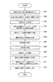
次に、図1の真空圧密地盤改良システムを用いた本実施形態の真空圧密による地盤改良方法の各工程S01〜S12について図3のフローチャートを参照して説明する。 Next, each step S01 to S12 of the ground improvement method by vacuum consolidation of the present embodiment using the vacuum consolidation ground improvement system of FIG. 1 will be described with reference to the flowchart of FIG.
まず、図2(a)の環状部28を鋼管29の内面上部に設ける(S01)。鋼管29としては、径800mm〜1000mm程度の鋼管が好ましく、鋼管杭(SKK400、490)、鋼管矢板(SKY400、SKY490)などの土木建築工事用の汎用品を用いることができる。
First, the
次に、改良対象の地盤近くの地中に鋼管29をバイブロハンマーなどによって打設することで(S02)、鋼管29を、例えば4m程度、地盤G1中に貫入させる。その後、オーガーまたはハンマーグラブ等により鋼管29内の土を掘削して排除する(S03)。これにより、地中に打設された鋼管29内に減圧空間20aを形成する。なお、掘削した土砂は地盤改良施工後に埋め戻すため、施工個所近辺に仮置きする。また、掘削土砂はプレロード荷重として利用してもよい。
Next, the
次に、鋼管29の底部側にコンクリート等による固化体を構築して底板27を設置する(S04)。これにより、減圧容器20の底面の強度を確保する。次に、排水管25が連結された揚水ポンプ24を鋼管29の底部に収納する(S05)。
Next, a solidified body made of concrete or the like is constructed on the bottom side of the
次に、排水管25,吸気管26および鉛直排水管21を貫通させた蓋体30を環状部28に静置する(S06)。この場合、蓋体30を、ボルト固定や溶接等で鋼管29に取り付けることは行わない。蓋体30は鋼板製またはPC(プレキャストコンクリート)板製が好ましく、工場製作される。また、蓋体30の静置方法としては、蓋体30に取り付けたフックに吊ワイヤーを掛けて、ワイヤーを降ろしながら静置する方法などがある。
Next, the
上記工程S06のとき、事前に環状部28に対応する蓋体30の下側領域に図2(b)のゴムパッキン31を接着しておくことで、現地においてパッキン31を配置する際の取り扱いが容易となり、パッキン31のメンテナンス性が向上する。なお、鋼管29の環状部28にパッキンを併せて設置しておくと止水性が向上する。パッキン31はゴム材料から構成できるが、他にシリコンなどで代用してもよい
At the time of the above-described step S06, the rubber packing 31 of FIG. 2 (b) is bonded in advance to the lower region of the
上述のようにして、減圧容器20を完成させるが(S07)、かかる減圧容器20の設置と並行して、または、前もって、図1のように鉛直ドレーン材11を改良対象の軟弱地盤G中に打設する。そして、不透気部12の先端に接続部(図示省略)などを介して、減圧容器20から延びる水平排水管22を連結する(S08)。
While the
次に、真空ポンプ23を駆動し(S09)、減圧容器20内を減圧することで、蓋体30に-70〜85kN/m2程度の高い負圧が作用し、このため、蓋体30と鋼管29の環状部28とが密着し(S10)、減圧容器20内の気密性が確保される。
Next, the
次に、真空ポンプ23による吸引力と鉛直排水管21のサイフォン機能による吸引力とを発揮させ併用し(S11)、軟弱地盤G中の間隙水を吸引し排水することで(S12)、真空圧密による地盤改良を行う。排水された水は、減圧容器20の底部に貯留し、揚水ポンプ24により排水管25から外部へ排出される。
Next, the suction force by the
図1の真空圧密地盤改良システム1において真空減圧装置10の真空ポンプ23で減圧容器20内の減圧空間20aを減圧することによる吸引力に加えて、地下水位面H0と減圧容器20内の水位面H1との水位差ΔH(=H0−H1)に起因するサイフォン機能による吸引力が発生し、これらの吸引力により軟弱地盤G内の間隙水を吸引することで軟弱地盤Gを圧密する。この真空圧密を、真空ポンプ23のみで吸引する場合と比べて水位差ΔHに起因する吸引力が加わる分だけより大きな吸引力で行うことができる。なお、減圧容器20内の水位面H1が鉛直排水管21の下端21aに達しない場合の水位差ΔHは、地下水位面H0と下端21aとの差である。
In the vacuum consolidation ground improvement system 1 of FIG. 1, in addition to the suction force by depressurizing the
従来の真空圧密地盤改良工法によれば真空ポンプのみでは吸引力が不足する場合は、盛土による載荷を併用していたのに対し、本実施形態のようにサイフォン機能による自然の力である吸引力を併用することにより、盛土による載荷を縮小したり省略できるため、使用資材・機材の節減や作業工期の短縮を期待することができる。また、従来の工法に比べて吸引力が増加するため、軟弱地盤が所定の強度に達するまでに要する地盤改良期間を短縮することができる。 According to the conventional vacuum consolidation ground improvement method, when the suction force is insufficient with only the vacuum pump, loading with embankment is used together, but the suction force that is the natural force due to the siphon function as in this embodiment By using together, loading by embankment can be reduced or omitted, so it can be expected to save materials and equipment and shorten the work period. In addition, since the suction force is increased as compared with the conventional construction method, the ground improvement period required for the soft ground to reach a predetermined strength can be shortened.
本実施形態では、真空ポンプ23による負圧が-50kN/m2程度に低下した場合においても、少なくとも-80kN/m2程度の作用負圧を鉛直ドレーン材11に発揮させるため、サイフォンを機能させる鉛直排水管の鉛直長さとして、少なくとも3m程度にすることが望ましい。
In the present embodiment, when the negative pressure by the
上述のように、減圧容器20は、サイフォン機能を発揮させるために鉛直に比較的長い鉛直排水管21を内部に収容するが、かかる鉛直排水管21を収容する容器本体を鋼管から構成するので、減圧容器20を容易に現地製作できる。このため、地盤改良の工期に与える影響が小さい。
As described above, the
また、減圧容器20は気密性を保つ構造であることが求められるが、本実施形態によれば、減圧容器20の容器本体を鋼管29から構成し、鋼管29の環状部28に蓋体30を静置する構造とし、真空ポンプ23の駆動時の負圧作用によって蓋体30が環状部28に密着することによって減圧容器20の内部の気密性を保つことができる。したがって、蓋体30を設置するとき、内部の気密性を保つための溶接やボルト固定等の工程が不必要なため、減圧容器20を現地で容易に製作することができる。
In addition, the
上述のように、減圧容器20の現地製作を容易にし強度を確保するために容器本体に鋼管を用いるが、現地で入手できる鋼管の径が多少大きくとも、かかる鋼管に対して環状部28の外径および内径を調整することで、容易に減圧容器20を現地で製作でき、また、径を一定にした蓋体30を用意するだけでよい。また、蓋体30は溶接などで鋼管に固着されていないため、長期にわたる地盤改良の期間中に減圧容器内で揚水ポンプ等の故障があった場合には、容易に蓋を取り外して、ポンプ交換等の対応が容易である。
As described above, a steel pipe is used for the container body in order to facilitate on-site production of the
また、減圧容器20は、現場製作タイプであり、工事完了後には解体される。すなわち、工事を行っていないときは、鋼管29に載置される蓋体30、揚水ポンプ24、鉛直排水管21、吸気管26、揚水ポンプ24と接続する排水管25のみを保管し管理しておけばよい。減圧容器20の容器本体であるとともに大きな容積を持つ鋼管29を保管することが不要であり、管理が容易である。
The
次に、図1,図2の構成における好ましい実施態様について図4〜図7を参照して説明する。 Next, a preferred embodiment in the configuration of FIGS. 1 and 2 will be described with reference to FIGS.
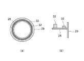
図4は、図2(b)のパッキンの別の構成例を示す上面図(a)および要部縦断面図(b)である。図5は、図4のパッキンと別の構成例を示す要部縦断面図である。 FIG. 4 is a top view (a) and a vertical cross-sectional view (b) of an essential part showing another configuration example of the packing of FIG. 2 (b). FIG. 5 is a longitudinal sectional view of a main part showing another configuration example of the packing of FIG.
図4(a)、(b)の例は、鋼管29の環状部28に配置する気密部材を2種類のパッキンから構成したものである。すなわち、本例の気密部材は、高さの高い低硬度のゴムパッキン32と、高さの低い高硬度のゴムパッキン33とから構成される。ゴムパッキン32を、例えば、硬度10度程度以下の低硬度のゴム材料から構成し、ゴムパッキン33を、例えば、硬度70度程度以上の高硬度のゴム材料から構成する。ゴムパッキン32の高さはゴムパッキン32よりも高い形状とする。
In the example of FIGS. 4A and 4B, the airtight member disposed in the
蓋体30と環状部28との間の気密部材には、減圧容器20内がある程度減圧されるまでは、主に蓋体30の自重による弱い圧縮力しか加わらず強い圧縮力が作用しないため気密が高まらない可能性があるのに対し、上述のように鋼管29の環状部28に配置する気密部材を軟硬二種類のゴムパッキン32,33から構成することで、低硬度のゴムパッキン32が弱い圧縮力下においても変形し気密をより高めることができるとともに、ゴムパッキン32よりも低い高硬度のゴムパッキン33を併せて配置することによって、減圧容器20室内で理論上の最大負圧-100kN/m2まで負圧が高まるような強い圧縮力が加わる条件においても、低硬度のゴムパッキン32の圧縮破壊を防止することができる。
The airtight member between the
なお、ゴム材料の硬度は、「加硫ゴム及び熱可塑性ゴムの硬さ試験方法」(JIS K6253)の規定に従い、デュロメータによって測定される。例えば、硬度が10度はA10、硬度が70度はA70と表示される。 The hardness of the rubber material is measured by a durometer in accordance with the provisions of “Hardness test method for vulcanized rubber and thermoplastic rubber” (JIS K6253). For example, a hardness of 10 degrees is displayed as A10, and a hardness of 70 degrees is displayed as A70.
減圧容器20内の減圧の過程で、低硬度のゴムパッキン32を最初に変形させる必要があるため、図4(b)のように、低硬度のゴムパッキン32は、高硬度のゴムパッキン33よりも高さが高いものを用いる。高硬度のゴムパッキン33は、低硬度のゴムパッキン32が変形してゴムパッキン33と同程度の高さとなってから、変形するが、その変形の度合いは、ゴムパッキン32よりも低く、ゴムパッキン32の過度の圧縮を防止できるとともに、気密性の向上に寄与し、気密性をさらに高めることができる。
Since it is necessary to first deform the low-hardness rubber packing 32 in the process of pressure reduction in the
なお、ゴムパッキン32,33の断面形状は、矩形状であってよいが、円形状や長円状であってもよい。また、図4(a)(b)では、環状部28においてゴムパッキン32がゴムパッキン33よりも内周側に位置するが、反対に外周側に位置してもよい。
In addition, although the cross-sectional shape of the
また、図5のように、図4(b)の低硬度のゴムパッキン32の代わりに、中空ゴムによるパッキン34を用いてもよく、中空ゴムによるパッキン34の高さをゴムパッキン33よりも高くする。この場合、パッキン34をゴムパッキン33と同じ硬度のゴム材料から構成してもよく、中空ゴムのパッキン34の方が中実のゴムパッキン33よりも変形し易い。
Further, as shown in FIG. 5, a hollow rubber packing 34 may be used instead of the low hardness rubber packing 32 of FIG. 4B, and the height of the hollow rubber packing 34 is higher than that of the rubber packing 33. To do. In this case, the packing 34 may be made of a rubber material having the same hardness as the rubber packing 33, and the hollow rubber packing 34 is more easily deformed than the
図6は、図1の打設後の鋼管の底板の位置に対して鋼管の下端位置を長くした構成例を説明するための図である。図7は、図1の打設後の鋼管の底板の位置に対して鋼管の下端位置が短い場合の問題を説明するための図(a)、および、図6の構成とした場合の効果を説明するための図(b)である。 FIG. 6 is a view for explaining a configuration example in which the lower end position of the steel pipe is lengthened with respect to the position of the bottom plate of the steel pipe after the placement shown in FIG. FIG. 7 is a diagram for explaining a problem when the lower end position of the steel pipe is short with respect to the position of the bottom plate of the steel pipe after the placement of FIG. It is figure (b) for demonstrating.
上述のように、鋼管29を打設し、底板27を設置することで、減圧空間20aを確保することができるが、図6のように、底板27の設置位置と、鋼管29の下端位置29aとの位置関係を、底板27の下面位置27aと鋼管29の下端位置29aとの間の長さhが鋼管29の径dの1/2以上となるようにすることが好ましい。すなわち、長さhを根入れ長さとすると、鋼管29の根入れ比(根入れ長h/鋼管径d)を1/2以上とする。このような根入れ比となるように鋼管29を打設し、底板27を設置する。
As described above, by placing the
図7(a)のように、鋼管29の根入れ比が小さい(底板27の下面位置27aと鋼管29の下端位置29aとの間の長さhが短い)と、地盤G1が軟弱な場合、上向きに作用する浮力Fが内部に空間20aを有する減圧容器20に作用し、このため、減圧容器20が浮き上がるといったおそれが生じ、減圧容器20の安定性が損なわれてしまうのに対し、鋼管29の根入れ比を大きくする(底板27の下面位置27aと鋼管29の下端位置29aとの間の長さhが長い)と、図7(b)のように、鋼管29がスカート状に伸びており、その内部が密閉されているためサクション力F1が働くとともに周辺摩擦力F2により鋼管29が移動することに対して抵抗することができる。すなわち、地盤G1が軟弱な場合に浮力Fが減圧容器20に作用しても、減圧容器20が浮き上がるおそれが生じ難く、減圧容器20が安定する。また、事前に製作した円筒状の減圧容器を現地に搬入し地中に埋設するようにして設置することも考えられるが、このような場合と比べて減圧容器20の安定性が高い。
As shown in FIG. 7 (a), when the penetration ratio of the
なお、山崎浩之らは、参考文献(山崎浩之、森川嘉之、小池二三勝、出野雅和、矢沢岳(2003):サクション構造物の基礎実験、港湾空港技術研究所報告、Vol.42、No.1)に示されるように、根入れ長/鋼管径で表す根入れ比が0.0、1/4、1/2、1/1の条件でサクション基礎構造物に荷重を与え、荷重と変位の関係を調べる実験を行っているが、実験の結果、根入れ比が大きいほど、荷重に対する変位や傾斜角が小さく、外力に対して安定性が高いことを示している。 In addition, Hiroyuki Yamazaki et al., References (Hiroyuki Yamazaki, Yoshiyuki Morikawa, Futatsuka Koike, Masakazu Deno, Takeshi Yazawa (2003): Basic experiments on suction structures, Report from the Port and Airport Research Institute, Vol.42 As shown in No. 1), a load is applied to the suction substructure under conditions where the penetration ratio represented by the penetration length / steel pipe diameter is 0.0, 1/4, 1/2, 1/1. Experiments have been conducted to investigate the relationship of displacement. As a result of the experiments, it is shown that the larger the penetration ratio, the smaller the displacement and the inclination angle with respect to the load, and the higher the stability against external force.
図8は、図1の鋼管の底部側に設置される底板について説明するための図である。上述のように、図1の鋼管29の底部側に設置される底板27は、コンクリート等の固化体から構成されるが、図8のように、減圧容器20内の減圧空間20aが減圧されると、その負圧により底板27に対し上方への力F3が作用し、底板27においてヒービング破壊や止水漏れのおそれが生じるが、かかるヒービング破壊や止水漏れを防止するために、固化体(底板27)の厚さを0.5m程度とすることが望ましい。なお、底板27のコンクリートと鋼管29の内面とが接触する位置には、付着性を高めるために鋼管29の内面にほぞなどを設けておくことが望ましい。
FIG. 8 is a view for explaining a bottom plate installed on the bottom side of the steel pipe of FIG. 1. As described above, the
以上のように本発明を実施するための形態について説明したが、本発明はこれらに限定されるものではなく、本発明の技術的思想の範囲内で各種の変形が可能である。例えば、図1において、鋼管29の打設後に底部側に底板27を設置するのでなく、底板27を予め所定位置に設置した鋼管を事前に用意して、底部側の気密および強度の確保を図るようにしてもよい。また、鋼管として、円筒状のものを用いたが、これに限定されず、角筒状のものを用いてもよい。
As described above, the modes for carrying out the present invention have been described. However, the present invention is not limited to these, and various modifications can be made within the scope of the technical idea of the present invention. For example, in FIG. 1, the
また、図1の減圧容器20内の気密性をさらに向上させるために、蓋体30の上に錘を載せたり、また、粘性土スラリー等で蓋体30の上部を被覆する等のことを行ってもよい。
Further, in order to further improve the airtightness in the
また、鉛直排水管21内でサイフォンが機能していることか否かは、管21内に気液2相流が形成されているか否かで判断することができるが、計測機器に頼ることなく、気液2相流の形成状況を外から観察・判断できるように、鉛直排水管21の少なくとも一部を透明材料から構成してもよく、また、蓋体を透明材料にしてもよい。
Further, whether or not the siphon is functioning in the
また、減圧容器20から排水管25を通して排水された水を水槽に貯水した後、鉛直排水管21に至る前の排水経路内に還流させ、鉛直排水管21内において水の流量を増加させるとともに、空気混合率を低下させて気泡の大きさを小さくすることにより、空気混入時においてもサイフォンを安定して機能させることができる。
In addition, after the water drained from the
また、本発明の地盤改良方法は、鋼管の天端および蓋体を水面以上に設置することにより、陸上地盤だけでなく、水底地盤に対しても適用可能である。 Moreover, the ground improvement method of the present invention can be applied not only to the land ground but also to the water bottom ground by installing the top end and the lid of the steel pipe above the water surface.
また、本発明の減圧容器は、真空ポンプによる吸引力とサイフォン機能による吸引力とを得ることができるものであるが、サイフォン機能を利用せずに真空ポンプによる吸引力だけで真空圧密による地盤改良を行う場合にも適用できることはもちろんである。 In addition, the decompression container of the present invention can obtain the suction force by the vacuum pump and the suction force by the siphon function, but the ground improvement by vacuum consolidation only by the suction force by the vacuum pump without using the siphon function. Of course, it can also be applied to the case of performing.
本発明の地盤改良方法および減圧容器によれば、地盤改良対象域で製作可能であり十分な強度と気密性を有する減圧容器を地中に設置できるので、真空ポンプによる吸引力とサイフォン機能による吸引力とを併用した真空圧密による地盤改良をコストがかからず工期を短縮して行うことができる。 According to the ground improvement method and the decompression container of the present invention, a decompression container that can be manufactured in the ground improvement target area and has sufficient strength and airtightness can be installed in the ground. Ground improvement by vacuum compaction combined with force can be done at low cost and with a shorter construction period.
1 真空圧密地盤改良システム 10 真空減圧装置 11 鉛直ドレーン材 20 減圧容器 20a 減圧空間 21 鉛直排水管(鉛直管) 23 真空ポンプ 24 揚水ポンプ 25 排水管 26 吸気管 27 底板 28 環状部(被設置部) 29 鋼管 30 蓋体 31,32,33 ゴムパッキン(気密部材) G 地盤、軟弱地盤 ΔH 水位差
DESCRIPTION OF SYMBOLS 1 Vacuum consolidation
Claims (7)
前記打設された鋼管内の土を排除する工程と、
前記鋼管の底部側に底板を設置する工程と、
前記鋼管内部に収納される揚水ポンプと連結する排水管と、真空ポンプと連結する吸気管と、サイフォンを機能させる鉛直管と、をそれぞれ貫通させた蓋体を前記鋼管の環状部に静置する工程と、により減圧容器を地中に完成させ、
次に、前記真空ポンプの駆動による負圧で前記蓋体を前記鋼管の環状部に密着させ、
前記真空ポンプによる吸引力と前記鉛直管のサイフォン機能による吸引力とを発揮させることで改良対象の地盤中の間隙水を、前記地盤に打設された鉛直ドレーン材を通して吸引し排水することを特徴とする地盤改良方法。 Placing a steel pipe having an annular portion protruding from the upper inner surface into the ground;
Removing the soil in the cast steel pipe;
Installing a bottom plate on the bottom side of the steel pipe;
The lid which penetrated the drainage pipe connected with the pumping pump housed in the steel pipe, the intake pipe connected to the vacuum pump, and the vertical pipe for functioning the siphon is placed in the annular portion of the steel pipe. And complete the decompression vessel in the ground by the process,
Next, the lid is brought into close contact with the annular portion of the steel pipe by negative pressure generated by driving the vacuum pump,
The suction water by the vacuum pump and the suction force by the siphon function of the vertical pipe are exerted to suck and drain the pore water in the ground to be improved through the vertical drain material placed on the ground. The ground improvement method.
容器本体として地中に打設される鋼管と、
前記容器本体の底部側に設けられる底板と、
前記容器本体を閉塞する蓋体と、を備え、
前記蓋体が前記容器本体の被設置部に静置される構造を有し、
前記真空ポンプの駆動による負圧で前記蓋体を前記被設置部に密着させることを特徴とする減圧容器。 A decompression vessel that is installed in the ground and whose inside is decompressed by a vacuum pump,
A steel pipe placed in the ground as a container body;
A bottom plate provided on the bottom side of the container body;
A lid for closing the container body,
The lid body has a structure that is placed on an installation portion of the container body,
A decompression container, wherein the lid is brought into close contact with the portion to be installed by a negative pressure generated by driving the vacuum pump.
前記環状部を前記被設置部として前記蓋体が前記環状部に載置され、
前記蓋体と前記環状部との間に弾性体からなる気密部材が配置される請求項4に記載の減圧容器。 The steel pipe has an annular portion provided so as to protrude from the upper inner surface thereof,
The lid is placed on the annular part with the annular part as the installation part,
The decompression container according to claim 4, wherein an airtight member made of an elastic body is disposed between the lid and the annular portion.
Priority Applications (2)
| Application Number | Priority Date | Filing Date | Title |
|---|---|---|---|
| JP2011111145A JP5713442B2 (en) | 2011-05-18 | 2011-05-18 | Ground improvement method and decompression vessel |
| SG2012023347A SG185873A1 (en) | 2011-05-18 | 2012-03-30 | Ground improvement method and decompression vessel |
Applications Claiming Priority (1)
| Application Number | Priority Date | Filing Date | Title |
|---|---|---|---|
| JP2011111145A JP5713442B2 (en) | 2011-05-18 | 2011-05-18 | Ground improvement method and decompression vessel |
Publications (2)
| Publication Number | Publication Date |
|---|---|
| JP2012241383A true JP2012241383A (en) | 2012-12-10 |
| JP5713442B2 JP5713442B2 (en) | 2015-05-07 |
Family
ID=47463405
Family Applications (1)
| Application Number | Title | Priority Date | Filing Date |
|---|---|---|---|
| JP2011111145A Active JP5713442B2 (en) | 2011-05-18 | 2011-05-18 | Ground improvement method and decompression vessel |
Country Status (2)
| Country | Link |
|---|---|
| JP (1) | JP5713442B2 (en) |
| SG (1) | SG185873A1 (en) |
Cited By (4)
| Publication number | Priority date | Publication date | Assignee | Title |
|---|---|---|---|---|
| CN105350514A (en) * | 2015-11-16 | 2016-02-24 | 南京电力工程设计有限公司 | Telescopic excess pore water dissipation casing pipe and construction method thereof |
| CN107326891A (en) * | 2017-07-14 | 2017-11-07 | 浙江大学 | A kind of soft foundation discharge fixing system and method |
| CN109750684A (en) * | 2019-03-05 | 2019-05-14 | 上海长凯岩土工程有限公司 | A kind of multi-purpose precipitation well construction and preparation method thereof |
| CN113737865A (en) * | 2021-09-02 | 2021-12-03 | 中国新兴建设开发有限责任公司 | Drainage pressure reducing device for solving sudden overhigh underground water level and construction method thereof |
Citations (3)
| Publication number | Priority date | Publication date | Assignee | Title |
|---|---|---|---|---|
| JP2001279657A (en) * | 2000-03-31 | 2001-10-10 | Hazama Gumi Ltd | Ground improvement structure and construction method |
| JP2009249863A (en) * | 2008-04-03 | 2009-10-29 | Kajima Corp | Surplus soil treatment device |
| JP2010090696A (en) * | 2009-11-02 | 2010-04-22 | Penta Ocean Construction Co Ltd | Suction force generation device and suction force generation method by siphon, and construction method for improving vacuum consolidated ground |
-
2011
- 2011-05-18 JP JP2011111145A patent/JP5713442B2/en active Active
-
2012
- 2012-03-30 SG SG2012023347A patent/SG185873A1/en unknown
Patent Citations (3)
| Publication number | Priority date | Publication date | Assignee | Title |
|---|---|---|---|---|
| JP2001279657A (en) * | 2000-03-31 | 2001-10-10 | Hazama Gumi Ltd | Ground improvement structure and construction method |
| JP2009249863A (en) * | 2008-04-03 | 2009-10-29 | Kajima Corp | Surplus soil treatment device |
| JP2010090696A (en) * | 2009-11-02 | 2010-04-22 | Penta Ocean Construction Co Ltd | Suction force generation device and suction force generation method by siphon, and construction method for improving vacuum consolidated ground |
Cited By (5)
| Publication number | Priority date | Publication date | Assignee | Title |
|---|---|---|---|---|
| CN105350514A (en) * | 2015-11-16 | 2016-02-24 | 南京电力工程设计有限公司 | Telescopic excess pore water dissipation casing pipe and construction method thereof |
| CN107326891A (en) * | 2017-07-14 | 2017-11-07 | 浙江大学 | A kind of soft foundation discharge fixing system and method |
| CN109750684A (en) * | 2019-03-05 | 2019-05-14 | 上海长凯岩土工程有限公司 | A kind of multi-purpose precipitation well construction and preparation method thereof |
| CN109750684B (en) * | 2019-03-05 | 2024-03-26 | 上海长凯岩土工程有限公司 | Multipurpose dewatering well structure and manufacturing method thereof |
| CN113737865A (en) * | 2021-09-02 | 2021-12-03 | 中国新兴建设开发有限责任公司 | Drainage pressure reducing device for solving sudden overhigh underground water level and construction method thereof |
Also Published As
| Publication number | Publication date |
|---|---|
| JP5713442B2 (en) | 2015-05-07 |
| SG185873A1 (en) | 2012-12-28 |
Similar Documents
| Publication | Publication Date | Title |
|---|---|---|
| US8668408B2 (en) | Skirted foundation for penetrating soft material | |
| JP5713442B2 (en) | Ground improvement method and decompression vessel | |
| KR101138033B1 (en) | Soil improvement method | |
| EP2925936B1 (en) | Double top suction pile and suction pile foundation | |
| CN103572770B (en) | A kind of stake case hydraulic structures and construction method thereof | |
| CN203654309U (en) | Pile-caisson hydraulic structure | |
| KR20190031868A (en) | Suction foundation using inner wall and offshare structure using thereof | |
| EP2236677A2 (en) | Method for creating a building under an architectural monument | |
| JP5213216B2 (en) | Ground improvement method | |
| CN110106907A (en) | A kind of suction caisson foundation and cement mixing method reinforce association | |
| CN201202114Y (en) | Bearing pile | |
| CN106400814A (en) | Foundation pit supporting method | |
| KR20160025064A (en) | Suction foundation for pre-loading and construction method thereof | |
| JP2007303095A (en) | Ground improvement construction method | |
| JP2006070513A (en) | Height adjusting method of structure | |
| JP2004190374A (en) | Soft ground improving method and soft ground improving unit | |
| CN211904141U (en) | Accelerator collimation permanent bedrock point structure | |
| KR20150019100A (en) | Suction Foundation, Assembly, Construction Method for Adjusting Horizontality and Offshore Wind Power System using the same | |
| JP5519722B2 (en) | Ground improvement method | |
| JP2013204413A (en) | Method and system for lowering groundwater level using vacuum deep well | |
| CN107640289B (en) | A kind of semi-buried square foundation and its installation method | |
| CN207828973U (en) | A kind of processing system that building special foundation is reinforced | |
| JP5512422B2 (en) | Decompression unit and vacuum consolidation ground improvement method | |
| JP4080421B2 (en) | How to adjust the height of the structure | |
| US20090114473A1 (en) | Shear wave generator |
Legal Events
| Date | Code | Title | Description |
|---|---|---|---|
| A621 | Written request for application examination |
Free format text: JAPANESE INTERMEDIATE CODE: A621 Effective date: 20140402 |
|
| A977 | Report on retrieval |
Free format text: JAPANESE INTERMEDIATE CODE: A971007 Effective date: 20141211 |
|
| A131 | Notification of reasons for refusal |
Free format text: JAPANESE INTERMEDIATE CODE: A131 Effective date: 20141226 |
|
| A521 | Request for written amendment filed |
Free format text: JAPANESE INTERMEDIATE CODE: A523 Effective date: 20150212 |
|
| TRDD | Decision of grant or rejection written | ||
| A01 | Written decision to grant a patent or to grant a registration (utility model) |
Free format text: JAPANESE INTERMEDIATE CODE: A01 Effective date: 20150305 |
|
| A61 | First payment of annual fees (during grant procedure) |
Free format text: JAPANESE INTERMEDIATE CODE: A61 Effective date: 20150306 |
|
| R150 | Certificate of patent or registration of utility model |
Ref document number: 5713442 Country of ref document: JP Free format text: JAPANESE INTERMEDIATE CODE: R150 |
|
| R250 | Receipt of annual fees |
Free format text: JAPANESE INTERMEDIATE CODE: R250 |
|
| R250 | Receipt of annual fees |
Free format text: JAPANESE INTERMEDIATE CODE: R250 |
|
| R250 | Receipt of annual fees |
Free format text: JAPANESE INTERMEDIATE CODE: R250 |
|
| R250 | Receipt of annual fees |
Free format text: JAPANESE INTERMEDIATE CODE: R250 |