JP2012241355A - Installation structure of frame peripheral member of opening device - Google Patents
Installation structure of frame peripheral member of opening device Download PDFInfo
- Publication number
- JP2012241355A JP2012241355A JP2011110211A JP2011110211A JP2012241355A JP 2012241355 A JP2012241355 A JP 2012241355A JP 2011110211 A JP2011110211 A JP 2011110211A JP 2011110211 A JP2011110211 A JP 2011110211A JP 2012241355 A JP2012241355 A JP 2012241355A
- Authority
- JP
- Japan
- Prior art keywords
- frame
- fixing
- fixed
- opening device
- wall material
- Prior art date
- Legal status (The legal status is an assumption and is not a legal conclusion. Google has not performed a legal analysis and makes no representation as to the accuracy of the status listed.)
- Granted
Links
Images


Landscapes
- Door And Window Frames Mounted To Openings (AREA)
- Finishing Walls (AREA)
Abstract
Description
本発明は、サッシやドアなどの開口部装置の枠体に沿って設けられる庇部材や、水切部材などの設置構造に関するものである。 The present invention relates to an installation structure such as a gutter member or a draining member provided along a frame of an opening device such as a sash or a door.
従来、サッシやドアなどの開口部装置においては、四周の枠体を額縁部材にて取り囲む形態や、枠体の上部に庇部材を設ける形態や、枠体の下部に水切部材を設ける形態が知られており、関連する技術について開示する文献も存在する。 Conventionally, in an opening device such as a sash or a door, there are known a form in which a frame body around four sides is surrounded by a frame member, a form in which a heel member is provided in the upper part of the frame body, and a form in which a draining member is provided in the lower part of the frame body There are also documents that disclose related technologies.
特許文献1では、サッシの枠体の周囲を取り囲むように額縁部材を設置する形態について開示するものであり、額縁部材は外壁材の外面に対してネジ止めされることとしている。 In patent document 1, it discloses about the form which installs a frame member so that the circumference | surroundings of the frame body of a sash may be enclosed, and it is supposed that a frame member is screwed with respect to the outer surface of an outer wall material.
特許文献2では、サッシの枠体の上枠に形成されるレールの部位のうち、もっとも外側にあるレールの部位に取付ける庇部材について開示がなされている。
In
しかしながら、特許文献1のように、額縁部材を外壁材にネジ止めする形態では、外壁材の損傷や、ネジ止め部からの浸水などの課題が生じることになる。また、額縁部材が外壁材の裏側に設置される下地に対してネジ止めされる場合には、外壁材の裏側に配置される下地材と水切部材の位置合わせを行う必要があり、下地材の位置を確認しながらの作業が必要であった。 However, in the form in which the frame member is screwed to the outer wall material as in Patent Document 1, problems such as damage to the outer wall material and water immersion from the screwing portion occur. In addition, when the frame member is screwed to the base installed on the back side of the outer wall material, it is necessary to align the base material disposed on the back side of the outer wall material with the draining member. Work while confirming the position was necessary.
また、特許文献2のように上枠のレールの部位に取付ける形態では、サッシの仕様によっては、窓や網戸の開閉に支障が生じることが懸念される。
Moreover, in the form attached to the rail part of an upper frame like
そこで、本発明は、以上の問題に鑑み、開口部装置の周囲の部位に設けられる庇部材、水切部材、額縁部材などの各部材を設置するための新規な技術を提案するものである。 Therefore, in view of the above problems, the present invention proposes a novel technique for installing each member such as a scissor member, a draining member, and a frame member provided in a region around the opening device.
本発明の解決しようとする課題は以上の如くであり、次にこの課題を解決するための手段を説明する。 The problem to be solved by the present invention is as described above. Next, means for solving the problem will be described.
即ち、請求項1に記載のごとく、
開口部装置と外壁材の境界部に配置される枠周り部材が、
前記開口部装置の枠部材と、前記外壁材の間の箇所を通して躯体側に固定される、開口部装置の枠周り部材の設置構造とするものである。
That is, as described in claim 1,
A frame periphery member arranged at the boundary between the opening device and the outer wall material,
In this structure, the frame surrounding member of the opening device is fixed to the housing side through a portion between the frame member of the opening device and the outer wall material.
また、請求項2に記載のごとく、
前記枠周り部材は、
前記躯体に固定される前記開口部装置の枠部材、又は、
前記躯体に固定される受部材に対して取付けられることで、
前記躯体側に固定される、
こととするものである。
Moreover, as described in
The frame periphery member is
A frame member of the opening device fixed to the housing, or
By being attached to the receiving member fixed to the housing,
Fixed to the housing side,
It is something to do.
また、請求項3に記載のごとく、
前記枠周り部材は、
前記開口部装置の枠部材、又は、
前記躯体に固定される受部材に対して嵌合固定される、
こととするものである。
Moreover, as described in
The frame periphery member is
A frame member of the opening device, or
It is fitted and fixed to a receiving member fixed to the housing.
It is something to do.
また、請求項4に記載のごとく、
前記枠周り部材は、庇部材、水切部材、又は、額縁部材のいずれかである、こととするものである。
Moreover, as described in
The frame surrounding member is any one of a collar member, a draining member, and a frame member.
また、請求項5に記載のごとく、
前記枠周り部材は、
室内側の固定部と、室外側の部材の少なくとも二部材で構成される、こととするものである。
Moreover, as described in
The frame periphery member is
It is assumed to be composed of at least two members, a fixed portion on the indoor side and a member on the outdoor side.
また、請求項6に記載のごとく、
前記固定部を固定後に、前記室外側の部材を前記固定部に固定する、こととするものである。
Moreover, as described in claim 6,
After fixing the fixing part, the outdoor member is fixed to the fixing part.
本発明の効果として、以下に示すような効果を奏する。 As effects of the present invention, the following effects can be obtained.
即ち、請求項1に記載の発明においては、
枠周り部材の固定について、外壁材に対するネジ止めが行われないため、外壁材の損傷や、ネジ止め部からの浸水といった不具合の発生を防止できる。
That is, in the invention according to claim 1,
As for fixing the frame surrounding member, since the screws are not fixed to the outer wall material, it is possible to prevent the occurrence of problems such as damage to the outer wall material and water immersion from the screw fixing portion.
また、請求項2に記載の発明においては、
枠周り部材の固定について、外壁材に対するネジ止めが行われないため、外壁材の損傷や、ネジ止め部からの浸水といった不具合の発生を防止できる。
In the invention according to
As for fixing the frame surrounding member, since the screws are not fixed to the outer wall material, it is possible to prevent the occurrence of problems such as damage to the outer wall material and water immersion from the screw fixing portion.
また、請求項3に記載の発明においては、
枠周り部材の取付を容易に行うことができ、作業性に優れた構成を実現することができる。
In the invention according to
The frame periphery member can be easily attached, and a configuration excellent in workability can be realized.
また、請求項4に記載の発明においては、
庇部材、水切部材、又は、額縁部材について本発明を適用することができる。
In the invention according to
The present invention can be applied to a scissor member, a draining member, or a frame member.
また、請求項5に記載の発明においては、
例えば、固定部を共通の部品として使用するとともに、室外側の部材を施工箇所に応じて選定するといったことが可能となる。
In the invention according to
For example, it is possible to use the fixed portion as a common component and to select the outdoor member according to the construction location.
また、請求項6に記載の発明においては、
固定部を単独で躯体側に固定可能となり、固定部の固定作業、及び、固定部に対する室外側の部材の固定作業を、それぞれ容易に行うことが可能となる。特に、室外側の部材が大型となる場合においては、まず、固定部を固定することによって、その後の室外側の部材の固定部に対する固定作業が容易にできることとなる。
In the invention according to claim 6,
The fixing part can be fixed to the housing side independently, and the fixing work of the fixing part and the fixing work of the outdoor member to the fixing part can be easily performed. In particular, when the outdoor member becomes large, first, the fixing portion is first fixed, so that the fixing operation of the outdoor member after that can be easily performed.
本発明は、図3に示す代表的な実施例に示されるように、
開口部装置(サッシ1)と外壁材2Aの境界部に配置される枠周り部材(庇部材10)が、サッシ1の枠部材(上枠部材40)と外壁材2Aの間の箇所(間に形成される隙間100)を通して躯体4側に固定される、こととするものである。
As shown in the exemplary embodiment shown in FIG.
The frame surrounding member (saddle member 10) arranged at the boundary between the opening device (sash 1) and the
これにより、枠周り部材の固定について、外壁材2Aに対するネジ止めが行われないため、外壁材2Aの損傷や、ネジ止め部からの浸水といった不具合の発生を防止できる。なお、「開口部装置の枠部材と、前記外壁材の間の箇所を通して躯体側に固定される」とは、外壁材よりも室外側に配置される部位を有する枠周り部材を、外壁材よりも室内側に配置される躯体側に固定するために、外壁材2A(端面2m)と枠部材(上枠部材40)の境界部の空間(以下の実施例では隙間100)を利用することを意味するものである。
Thereby, since the screwing to the
また、図3に示すごとく、枠周り部材としての庇部材10は、躯体4に固定されるサッシ1の枠部材(上枠部材40)、又は、躯体4に固定される受部材30に対して取付けられることで、躯体4側に固定される、こととするものである。
Further, as shown in FIG. 3, the
なお、以下で説明する実施例では受部材30を用いる実施形態としたが、受部材30の嵌合部35(図6(a)参照)の部位を、図5に示すように、枠部材(上枠部材40Aの)に嵌合部35Aを形成してもよい。つまり、外壁材2Aと枠部材(上枠部材40Aの上面部41A)の間の箇所に、嵌合部35Aを形成するものである。なお、図5の例では、上面部41Aに厚肉部41nを設け、この厚肉部41nの上側に嵌合部35Aが形成されることとしている。なお、嵌合部35(図4参照)や、嵌合部35A(図5参照)については、外壁材2Aよりも室外側に配置されるものであってもよい。
In addition, although it was set as embodiment using the receiving
これにより、枠周り部材の固定について、外壁材2Aに対するネジ止めが行われないため、外壁材2Aの損傷や、ネジ止め部からの浸水といった不具合の発生を防止できる。なお、特に、枠部材と別体の受部材30を用いる形態によれば、枠部材の形状を問わずに本発明を適用することができ、汎用性の広い構成とすることができる。
Thereby, since the screwing to the
また、図3及び図4(a)〜(c)に示すごとく、枠周り部材としての庇部材10は、サッシ1の枠部材(上枠部材40)、又は、躯体4に固定される受部材30に対して嵌合固定される、こととするものである。
Further, as shown in FIGS. 3 and 4A to 4C, the
これにより、枠周り部材の取付を容易に行うことができ、作業性に優れた構成を実現することができる。 Thereby, attachment of a frame periphery member can be performed easily and the structure excellent in workability | operativity can be implement | achieved.
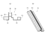
また、図1に示すごとく、前記枠周り部材は、庇部材10、水切部材20、又は、額縁部材8・9のいずれかである、こととするものである。
Moreover, as shown in FIG. 1, the said frame periphery member shall be either the
これにより、これら庇部材10、水切部材20、又は、額縁部材8・9について本発明を適用することができる。
Thereby, this invention is applicable about these
また、図3に示すごとく、枠周り部材(庇部材10)は、室内側の固定部11と、室外側の部材(庇形成部12)の二部材で構成している。なお、本明細書中における室内側、室外側とは、各部位の相対位置を特定する場合における室内寄り、室外寄りを意味するものであり、実際に室内、室外に存在することを意味するものではない。
Moreover, as shown in FIG. 3, the frame periphery member (saddle member 10) is comprised by two members, the indoor side fixing | fixed
これにより、例えば、固定部11を共通の部品として使用するとともに、室外側の部材(庇形成部12)を施工箇所に応じて選定するといったことが可能となる。
Thereby, for example, while using the fixing | fixed
また、図3及び図4に示すごとく、室内側の固定部11を固定後に、室外側の部材(庇形成部12)を固定部11に固定する構成としている。
Further, as shown in FIGS. 3 and 4, after fixing the indoor-
この構成によれば、固定部11を単独で躯体側(受部材30)に固定可能となり、受部材30に対する固定部11の固定作業、及び、固定部11に対する室外側の部材(庇形成部12)の固定作業を、それぞれ容易に行うことが可能となる。特に、室外側の部材が大型となる場合においては、まず、固定部11を固定することによって、その後の室外側の部材の固定部11に対する固定作業が容易にできることとなる。
According to this configuration, the fixing
以下図面を参照しながら本発明の実施形態について説明する。
図1は、本発明に係る枠周り部材としての庇部材10や、水切部材20の取付けの概要について示す図である。図示せぬ躯体に対し、開口部装置としてのサッシ1や、外壁材2A・2B・2Cが固定され、サッシ1と外壁材2A・2B・2Cの境界部に、庇部材10や水切部材20が配置されるようになっている。
Embodiments of the present invention will be described below with reference to the drawings.
FIG. 1 is a view showing an outline of attachment of a
また、図2は、サッシ1と外壁材2A・2Cが躯体4・5に対し固定された状態について示す縦断面図である。
図2に示すごとく、躯体4に対しサッシ1の上部に配置される上枠部材40が固定され、この上枠部材40の室外側斜め上方に、庇部材10が配置される。また、躯体5に対しサッシ1の下部に配置される下枠部材45が固定され、この下枠部材45の室外側斜め下方に、水切部材20が配置される。
FIG. 2 is a longitudinal sectional view showing a state in which the sash 1 and the
As shown in FIG. 2, the
次に、サッシなどの上部に設けられる庇部材の設置構造について説明する。
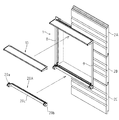
また、図3は、庇部材10の設置構造について示す縦断面図である。
図3に示すごとく、サッシの上枠部材40の固定片43は躯体4に対し固定されており、また、庇部材10を取付けるための受部材30が、スペーサー材3(胴縁などの場合もある)を介して躯体4に対して固定される。
Next, the installation structure of the eaves member provided in the upper part of a sash etc. is demonstrated.
FIG. 3 is a longitudinal sectional view showing the installation structure of the
As shown in FIG. 3, the fixing
また、図3に示すごとく、庇部材10は、躯体4側に固定される受部材30に取付けられ、外壁材2Aから室外側に突出する状態で設けられている。また、庇部材10は、サッシの上枠部材40の上方であって、その先端の部位が、上枠部材40よりも室外側に配置されるようになっている。
Moreover, as shown in FIG. 3, the
また、図3に示すごとく、庇部材10は、例えば、アルミなどを押出成型、又は、金属板材を板金加工した長尺の部材にて構成することができる。本実施例では、受部材30側に固定される固定部11と、固定部11に固定されて軒裏12aを形成する庇形成部12と、から構成されている。
Moreover, as shown in FIG. 3, the
また、図3及び図4(b)に示すごとく、庇部材10の固定部11は、断面視略L字状の部材にて構成され、室外側の部位における上部と下部には、係合片部11b・11cが設けられる。また、固定部11の室内側の部位には、受部材30に形成される嵌合部35に嵌合される嵌合部11aが設けられる。この嵌合部11aは、溝状の嵌合部35に嵌入される二列の突条にて構成される。また、庇部材10の固定部11には、庇形成部12の室内側の下部12dを下側から支持するための支持片部11dが設けられる。
Further, as shown in FIGS. 3 and 4B, the fixing
また、図3及び図4(c)に示すごとく、庇部材10の庇形成部12は、中空の長尺部材にて構成される。また、庇形成部12の室内側の部位には、固定部11の係合片部11b・11cにそれぞれ係合するための係合片部12b・12cが設けられる。
Moreover, as shown in FIG.3 and FIG.4 (c), the
また、図4(c)に示すごとく、庇部材10の固定部11の係合片部11b・11cに対し、庇形成部12の係合片部12b・12cを係合させることで、固定部11と庇形成部12の仮固定がなされ、その後、固定具53を用いた固定部11と庇形成部12の固定がなされるようになっている。本実施例では、まず上部の係合片部11b・12b同士を係合し、庇形成部12を倒すようにすることで、下部の係合片部11c・12c同士の係合が行われるようになっており、仮固定の作業が行いやすい構造となっている。
Further, as shown in FIG. 4 (c), by engaging the
また、図6(a)(b)は、受部材30の構造について示している。
受部材30は、アルミなどを押出成型、又は、金属板材を板金加工した長尺の部材であって、施工現場において、開口部装置の枠の長さ寸法に対応するように、切断加工などによる調整が適宜行うことができるものである。
6A and 6B show the structure of the receiving
The receiving
また、図4(a)及び図6(a)(b)に示すごとく、受部材30は、スペーサー材3に対する設置面31・32と、この設置面31・32の表面側方向に突出する二つの壁面部33・34を有して構成される。また、壁面部33・34の間には、溝状の嵌合部35が形成される。
Further, as shown in FIGS. 4A and 6A and 6B, the receiving
また、図3及び図6(a)(b)に示すごとく、設置面31・32の表面側には、それぞれパッキン材P1・P2が設けられている。パッキン材P1は、設置面31と上枠部材40(上面部41)の間に介挿される。パッキン材P2は、設置面32と外壁材2Aの裏面の間に介挿される。このパッキン材P1・P2は、例えば、ゴム、樹脂、スポンジなどの部材にて構成される。なお、受部材30の具体的構成については、枠周り部材としての庇部材10(或いは水切部材、額縁部材)を固定できるものであれば、上記説明及び各図に開示される形態に限定されるものではない。
Further, as shown in FIGS. 3 and 6A and 6B, packing materials P1 and P2 are provided on the surface sides of the installation surfaces 31 and 32, respectively. The packing material P1 is interposed between the
また、図3に示すごとく、壁面部34と外壁材2A(端面2m)の間には、シーリング材S2が充填される。これにより、上枠部材40(上面部41)と外壁材2Aの間の箇所(間に形成される隙間100)が、シーリング材S2、及び、受部材30によって塞がれるようになっている。
Further, as shown in FIG. 3, a sealing material S2 is filled between the
そして、以上のようにして、図3に示すごとくパッキン材P1によって、受部材30と上枠部材40の上面部41の間の止水を実施することがきる。これにより、受部材30と上枠部材40の間から室内側に水が浸入することを防止することができる。
And as mentioned above, the water stop between the receiving
また、図3に示すごとく、シーリング材S2、及び、パッキン材P2によって、受部材30と外壁材2Aの端面2mの間の止水を二段階で実施することができる。これにより、受部材30と外壁材2A(端面2m)の間から室内側に水が浸入することを防止することができる。
Moreover, as shown in FIG. 3, water sealing between the receiving
また、図4(a)〜(c)は、庇部材10の取付手順について説明する図である。
この取付手順について説明すると、図4(a)に示すごとく、まず、サッシの上枠部材40が固定された躯体4(スペーサー材3)に対し、ビスなどの固定具51を用いて受部材30を固定する。なお、スペーサー材3が設けられない施工箇所においては、受部材30が躯体4に直接固定されることが考えられる。
FIGS. 4A to 4C are diagrams for explaining the attachment procedure of the
This attachment procedure will be described. As shown in FIG. 4A, first, the receiving
次に、図4(b)に示すごとく、外壁材2Aの設置を行うとともに、外壁材2Aと受部材30(壁面部34)の間にシーリング材S2が充填される。
Next, as shown in FIG. 4B, the
次に、図4(b)に示すごとく、庇部材10の固定部11の嵌合部11aを、受部材30の嵌合部35に嵌合させるとともに、固定具52にて固定部11を受部材30に対して固定する。なお、固定具52を用いた固定を行うことにより、受部材30に対する固定部11の固定を強固に行うことができ、固定部11の意図せぬ脱落や、風による吹き上げ荷重による脱落などの不具合をより確実に抑制可能となる。
Next, as shown in FIG. 4B, the
次に、図4(c)に示すごとく、庇形成部12の室外側を高くして傾けた状態とし、庇形成部12の室内側上部の係合片部12bを固定部11の係合片部11bに係合させ、その後、庇形成部12の室外側を下げるように倒すことで、下部の係合片部11c・12c同士を係合させる。その後、固定具53にて、固定部11と庇形成部12が固定される。なお、固定具53を用いた固定を行うことにより、固定部11に対する庇形成部12の固定を強固に行うことができ、庇形成部12の意図せぬ脱落や、風による吹き上げ荷重による脱落などの不具合をより確実に抑制可能となる。
Next, as shown in FIG. 4 (c), the outdoor side of the
そして、図3及び図4(a)に示すごとく、以上に述べた庇部材10の設置構造においては、外壁材2Aに対するネジ止めが行われないため、外壁材2Aの損傷や、ネジ止め部からの浸水といった不具合の発生を防止できる。また、庇部材10が上枠部材40のレールの部位(垂片42a・42bの部位)に取付けられないため、窓や網戸の開閉に支障が生じることもない。また、庇部材10は受部材30に対して固定されるため、外壁材2Aの裏側に配置される下地と水切部材20の位置合わせを行う必要がない。
As shown in FIGS. 3 and 4 (a), in the installation structure of the
また、図3及び図4(c)に示すごとく、本実施例では、庇部材10を、室内側の固定部11と、室外側の庇形成部12のように二部材で構成している。なお、このほか、固定部11と庇形成部12の間に別の部材を介装するなどしてもよく、少なくとも固定部11と庇形成部12を有する構成であれば、本実施例に沿う形態となる。
Further, as shown in FIGS. 3 and 4 (c), in this embodiment, the
この構成によれば、例えば、固定部11を共通の部品として使用するとともに、庇形成部12を施工箇所に応じて選定するといったことが可能となる。つまり、各施工箇所における仕様に応じて、外壁材からの出幅の大きい庇形成部を選定、或いは、出幅の小さい庇形成部を選定、といった選定の自由度を確保することができる。また、庇形成部12のほかに、別の化粧部材(意匠部材)を取付けることも可能であり、バリエーションに富んだ実施態様を確保することができる。なお、本実施例の他、庇部材10を一部材で構成する実施形態も考えられる。
According to this configuration, for example, it is possible to use the fixing
また、図3及び図4に示すごとく、室内側の固定部11を受部材30に固定後に、室外側の庇形成部12を固定部11に固定する構成としている。
As shown in FIGS. 3 and 4, after fixing the indoor-
この構成によれば、固定部11を単独で受部材30に固定可能となり、受部材30に対する固定部11の固定作業、及び、固定部11に対する庇形成部12の固定作業を、それぞれ容易に行うことが可能となる。特に、庇形成部12が大型となる場合においては、まず、固定部11を固定することによって、その後の庇形成部12の固定部11に対する固定作業が容易にできることとなる。
According to this configuration, the fixing
次に、サッシなどの下部に設けられる水切部材の設置構造について説明する。
また、図7は、水切部材20の設置構造について示す縦断面図である。
図7に示すごとく、サッシの下枠部材45の固定片46が躯体5に対し固定される。また、水切部材20を取付けるための受部材30Aが、スペーサー材3(胴縁などの場合もある)を介して躯体5に対して固定される。
Next, the installation structure of the draining member provided in the lower part of a sash etc. is demonstrated.
FIG. 7 is a longitudinal sectional view showing the installation structure of the draining
As shown in FIG. 7, the fixing
また、図7に示すごとく、水切部材20は、躯体5側に固定される受部材30Aに取付けられ、外壁材2Cから室外側に突出する状態で設けられている。また、水切部材20は、サッシの下枠部材45の下方であって、その先端の部位が、下枠部材45よりも室外側に配置されるようになっている。
Moreover, as shown in FIG. 7, the draining
また、図7に示すごとく、水切部材20は、例えば、アルミなどを押出成型、又は、金属板材を板金加工した長尺の部材にて構成することができる。本実施例では、受部材30A側に固定される固定部21と、固定部21に固定されて上面に水切面22aを形成する水切形成部22と、から構成されている。
Moreover, as shown in FIG. 7, the draining
また、図8(b)に示すごとく、水切部材20の固定部21は、断面視略コ字状の部材にて構成され、室外側における上部と下部には、係合片部21b・21cが設けられる。また、固定部21の室内側の部位には、受部材30Aに形成される嵌合部35に嵌合される嵌合部21aが設けられる。この嵌合部21aは、溝状の嵌合部35に嵌入される二列の突条にて構成される。
Further, as shown in FIG. 8 (b), the fixing
また、図8(c)に示すごとく、水切部材20の水切形成部22には、固定部21の係合片部21b・21cにそれぞれ係合するための係合片部22b・22cが設けられる。そして、固定部21の係合片部21b・21cに対し、水切形成部22の係合片部22b・22cを係合させることで、固定部21と水切形成部22の固定がなされるようになっている。本実施例では、まず上部の係合片部21b・22b同士を係合し、水切形成部22を倒すようにすることで、下部の係合片部21c・22c同士の係合が行われるようになっており、固定の作業が行いやすい構造となっている。
Moreover, as shown in FIG.8 (c), the
また、図7及び図8(a)で示される受部材30Aは、図6(a)(b)に示す受部材30の構造と同様であるため説明を省略する。なお、パッキン材の有無については、受部材の設置箇所に応じて適宜選定することとしてもよい。
The receiving
また、図7及び図8(b)に示すごとく、壁面部34と外壁材2C(端面2n)の間には、シーリング材S4が充填される。これにより、下枠部材45と外壁材2Cの間の箇所(間に形成される隙間100A)が、シーリング材S4、及び、受部材30Aによって塞がれるようになっている。
Moreover, as shown in FIG.7 and FIG.8 (b), between the
以上のようにして、図7に示すごとく、パッキン材P1によって、受部材30Aと下枠部材45の下面部47の間の止水を実施することがきる。これにより、受部材30Aと下枠部材45の間から室内側に水が浸入することを防止することができる。
As described above, as shown in FIG. 7, water sealing between the receiving
また、図7に示すごとく、同様に、シーリング材S4、及び、パッキン材P2によって、受部材30Aと外壁材2Cの端面2nの間の止水を二段階実施することができる。これにより、受部材30Aと外壁材2C(端面2n)の間から室内側に水が浸入することを防止することができる。
Further, as shown in FIG. 7, similarly, the sealing material S4 and the packing material P2 can be used to stop water between the receiving
また、図8(a)〜(c)は、水切部材20の取付手順について説明する図である。
この取付手順について説明すると、図8(a)に示すごとく、まず、サッシの下枠部材45が固定された躯体5(スペーサー材3)に対し、ビスなどの固定具55を用いて受部材30Aを固定する。なお、スペーサー材3が設けられない施工箇所においては、受部材30Aが躯体5に直接固定されることが考えられる。
FIGS. 8A to 8C are views for explaining the procedure for attaching the draining
This attachment procedure will be described. As shown in FIG. 8A, first, the receiving
次に、図8(b)に示すごとく、外壁材2Cの設置を行うとともに、外壁材2Cと受部材30A(壁面部34)の間にシーリング材S4がそれぞれ充填される。
Next, as shown in FIG. 8B, the
次に、図8(b)に示すごとく、水切部材20の固定部21の嵌合部21aを、受部材30Aの嵌合部35に嵌合させるとともに、固定具56にて固定部21を受部材30Aに対して固定する。なお、固定具56を用いた固定を行うことにより、受部材30Aに対する固定部21の固定を強固に行うことができ、固定部21の意図せぬ脱落や、風による吹き上げ荷重による脱落などの不具合をより確実に抑制可能となる。
Next, as shown in FIG. 8B, the
次に、図8(c)に示すごとく、水切形成部22の室外側を高くして傾けた状態とし、水切形成部22の室内側上部の係合片部22bを固定部21の係合片部21bに係合させ、その後、水切形成部22の室外側を下げるように倒すことで、下部の係合片部21c・22c同士の係合が行われる。
Next, as shown in FIG. 8 (c), the outdoor side of the
そして、図7及び図8(a)〜(c)に示すごとく、以上に述べた水切部材20の設置構造においては、外壁材2Cに対するネジ止めが行われないため、外壁材2Cの損傷や、ネジ止め部からの浸水といった不具合の発生を防止できる。また、水切部材20は受部材30Aに対して固定されるため、外壁材2Cの裏側に配置される下地と水切部材20の位置合わせを行う必要がない。
And as shown in FIG.7 and FIG.8 (a)-(c), in the installation structure of the draining
また、図7及び図8(a)〜(c)に示すごとく、本実施例では、水切部材20を室内側の固定部21と、室外側の水切形成部22のように二部材で構成している。なお、このほか、固定部21と水切形成部22の間に別の部材を介装するなどしてもよく、少なくとも固定部21と水切形成部22を有する構成であれば、本実施例に沿う形態となる。
Further, as shown in FIGS. 7 and 8A to 8C, in this embodiment, the draining
この構成によれば、例えば、固定部21を共通の部品として使用するとともに、水切形成部22を施工箇所に応じて選定するといったことが可能となる。つまり、各施工箇所における仕様に応じて、外壁材からの出幅の大きい庇形成部を選定、或いは、出幅の小さい庇形成部を選定、といった選定の自由度を確保することができる。また、水切形成部22のほかに、別の化粧部材(意匠部材)を取付けることも可能であり、バリエーションに富んだ実施態様を確保することができる。なお、本実施例の他、水切部材20を一部材で構成する実施形態も考えられる。
According to this configuration, for example, the fixing
また、図7及び図8(a)〜(c)に示すごとく、室内側の固定部21を受部材30Aに固定後に、室外側の水切形成部22を固定部21に固定する構成としている。
Further, as shown in FIGS. 7 and 8A to 8C, after the indoor
この構成によれば、固定部21を単独で受部材30Aに固定可能となり、固定作業を容易に行うことが可能となる。特に、水切形成部22が大型となる場合においては、まず、固定部21を固定することによって、その後の水切形成部22の固定部21に対する固定作業を容易にできる。
According to this configuration, the fixing
また、以上に説明した実施例においては、開口部装置と外壁材の境界部に配置される枠周り部材(開口部装置の周囲の部位に設けられる部材(機能部材))として、庇部材や水切部材など水平方向に設置される部材の例を用いて説明したが、このほかにも、図1に示すごとく、サッシなどの開口部装置の縦枠と外壁材の境界部において、縦方向に設置される額縁部材8・9の設置についても、本発明は適用することができる。また、額縁部材8・9の場合においても、上述した庇部材10、水切部材20(図2参照)と同様に、室内側の固定部と、室外側の化粧部材(意匠部材)の二部材で構成することとしてもよい。また、枠周り部材としては、手すり、花台、シャッター、面格子、目隠し、といった機能部材、或いは、これら機能部材を支持するための部材も考えられる。
Further, in the embodiment described above, as a frame surrounding member (member (functional member) provided in a portion around the opening device) arranged at the boundary between the opening device and the outer wall material, the eaves member or the draining member is used. Although explained using an example of a member installed in a horizontal direction such as a member, as shown in FIG. 1, it is installed in a vertical direction at the boundary between a vertical frame of an opening device such as a sash and an outer wall material. The present invention can also be applied to the installation of the
さらに、図9に示す実施例のように、水切部材20Aのように、額縁部材8・9の下方に配置される端部水切部材20a・20bと、その間に配置される額縁部材20cの組み合わせからなる構成とすることも考えられる。端部水切部材20a・20bと額縁部材20cとは、一体であってもよく、別体であってもよい。端部水切部材20a・20bにおいては、額縁部材8・9から下方に流れる雨水などの水切りを行うことができる。
Further, as in the embodiment shown in FIG. 9, like the draining
この図9の例に示されるように、水切部材20Aなどの機能部材については、その長手方向において複数の部材からなる構成とすることもできる。また、長手方向において、必要な機能(例えば、図9の例のように、端部においてのみ水切の機能)を持たせることも可能であり、これによれば、部材の製作コストの低減や、意匠性の自由度を向上させることができる。
As shown in the example of FIG. 9, the functional member such as the draining
本発明の構成は、サッシ(窓)や玄関ドアなどの開口部装置と外壁材の境界部について、幅広く適用することが可能である。 The configuration of the present invention can be widely applied to a boundary portion between an opening device such as a sash (window) or an entrance door and an outer wall material.
1 サッシ
2A 外壁材
3 スペーサー材
4 躯体
5 躯体
10 庇部材
11 固定部
12 庇形成部
20 水切部材
30 受部材
35 嵌合部
40 上枠部材
45 下枠部材
P1 パッキン材
P2 パッキン材
S2 シーリング材
DESCRIPTION OF SYMBOLS 1
Claims (6)
前記開口部装置の枠部材と、前記外壁材の間の箇所を通して躯体側に固定される、
開口部装置の枠周り部材の設置構造。 A frame periphery member arranged at the boundary between the opening device and the outer wall material,
The frame member of the opening device is fixed to the housing side through a location between the outer wall materials,
Installation structure of members around the frame of the opening device.
前記躯体に固定される前記開口部装置の枠部材、又は、
前記躯体に固定される受部材に対して取付けられることで、
前記躯体側に固定される、
ことを特徴とする、請求項1に記載の開口部装置の枠周り部材の設置構造。 The frame periphery member is
A frame member of the opening device fixed to the housing, or
By being attached to the receiving member fixed to the housing,
Fixed to the housing side,
The installation structure of the frame periphery member of the opening part apparatus of Claim 1 characterized by the above-mentioned.
前記開口部装置の枠部材、又は、
前記躯体に固定される受部材に対して嵌合固定される、
ことを特徴とする、請求項1又は請求項2に記載の開口部装置の枠周り部材の設置構造。 The frame periphery member is
A frame member of the opening device, or
It is fitted and fixed to a receiving member fixed to the housing.
The installation structure of the frame periphery member of the opening part device according to claim 1 or 2, characterized by the above-mentioned.
ことを特徴とする、請求項1乃至請求項3のいずれか一項に記載の開口部装置の枠周り部材の設置構造。 The frame surrounding member is either a heel member, a draining member, or a frame member.
The installation structure of the frame periphery member of the opening device according to any one of claims 1 to 3, wherein
室内側の固定部と、室外側の部材の少なくとも二部材で構成される、
ことを特徴とする、請求項1乃至請求項4のいずれか一項に記載の開口部装置の枠周り部材の設置構造。 The frame periphery member is
It is composed of at least two members, a fixed part on the indoor side and a member on the outdoor side.
The installation structure of the frame periphery member of the opening device according to any one of claims 1 to 4, wherein
ことを特徴とする、請求項5に記載の開口部装置の枠周り部材の設置構造。
After fixing the fixing part, fixing the outdoor member to the fixing part,
The installation structure of the frame periphery member of the opening device according to claim 5.
Priority Applications (1)
| Application Number | Priority Date | Filing Date | Title |
|---|---|---|---|
| JP2011110211A JP5773482B2 (en) | 2011-05-17 | 2011-05-17 | Installation structure of members around the frame of the opening device |
Applications Claiming Priority (1)
| Application Number | Priority Date | Filing Date | Title |
|---|---|---|---|
| JP2011110211A JP5773482B2 (en) | 2011-05-17 | 2011-05-17 | Installation structure of members around the frame of the opening device |
Publications (2)
| Publication Number | Publication Date |
|---|---|
| JP2012241355A true JP2012241355A (en) | 2012-12-10 |
| JP5773482B2 JP5773482B2 (en) | 2015-09-02 |
Family
ID=47463377
Family Applications (1)
| Application Number | Title | Priority Date | Filing Date |
|---|---|---|---|
| JP2011110211A Active JP5773482B2 (en) | 2011-05-17 | 2011-05-17 | Installation structure of members around the frame of the opening device |
Country Status (1)
| Country | Link |
|---|---|
| JP (1) | JP5773482B2 (en) |
Cited By (2)
| Publication number | Priority date | Publication date | Assignee | Title |
|---|---|---|---|---|
| JP2014214521A (en) * | 2013-04-26 | 2014-11-17 | 旭化成ホームズ株式会社 | Eaves front end structure and eaves structure |
| JP2017089131A (en) * | 2015-11-04 | 2017-05-25 | Ykk Ap株式会社 | Installation structure of architrave member and installation method of architrave member |
Citations (8)
| Publication number | Priority date | Publication date | Assignee | Title |
|---|---|---|---|---|
| JPS5811037U (en) * | 1981-07-06 | 1983-01-24 | ワイケイケイ株式会社 | Eave mounting device |
| JPS6091745U (en) * | 1983-11-30 | 1985-06-22 | 立山アルミニウム工業株式会社 | eaves |
| JPH05321425A (en) * | 1992-05-22 | 1993-12-07 | Tostem Corp | Wall surface fitting structure body |
| JPH0743196U (en) * | 1993-12-29 | 1995-08-18 | 有限会社サンテクノ | Support bracket for eaves mounting |
| JP2000145078A (en) * | 1998-11-05 | 2000-05-26 | Inter Raito Kk | Connection type eaves |
| JP2002201864A (en) * | 2000-12-27 | 2002-07-19 | Shin Nikkei Co Ltd | Installing method of window frame in externally sticking heat insulating construction method and outer architrave |
| JP2009155935A (en) * | 2007-12-27 | 2009-07-16 | Sankyo Tateyama Aluminium Inc | Sash outer frame |
| JP2009191606A (en) * | 2009-06-02 | 2009-08-27 | Sankyo Tateyama Aluminium Inc | Sash |
-
2011
- 2011-05-17 JP JP2011110211A patent/JP5773482B2/en active Active
Patent Citations (8)
| Publication number | Priority date | Publication date | Assignee | Title |
|---|---|---|---|---|
| JPS5811037U (en) * | 1981-07-06 | 1983-01-24 | ワイケイケイ株式会社 | Eave mounting device |
| JPS6091745U (en) * | 1983-11-30 | 1985-06-22 | 立山アルミニウム工業株式会社 | eaves |
| JPH05321425A (en) * | 1992-05-22 | 1993-12-07 | Tostem Corp | Wall surface fitting structure body |
| JPH0743196U (en) * | 1993-12-29 | 1995-08-18 | 有限会社サンテクノ | Support bracket for eaves mounting |
| JP2000145078A (en) * | 1998-11-05 | 2000-05-26 | Inter Raito Kk | Connection type eaves |
| JP2002201864A (en) * | 2000-12-27 | 2002-07-19 | Shin Nikkei Co Ltd | Installing method of window frame in externally sticking heat insulating construction method and outer architrave |
| JP2009155935A (en) * | 2007-12-27 | 2009-07-16 | Sankyo Tateyama Aluminium Inc | Sash outer frame |
| JP2009191606A (en) * | 2009-06-02 | 2009-08-27 | Sankyo Tateyama Aluminium Inc | Sash |
Cited By (2)
| Publication number | Priority date | Publication date | Assignee | Title |
|---|---|---|---|---|
| JP2014214521A (en) * | 2013-04-26 | 2014-11-17 | 旭化成ホームズ株式会社 | Eaves front end structure and eaves structure |
| JP2017089131A (en) * | 2015-11-04 | 2017-05-25 | Ykk Ap株式会社 | Installation structure of architrave member and installation method of architrave member |
Also Published As
| Publication number | Publication date |
|---|---|
| JP5773482B2 (en) | 2015-09-02 |
Similar Documents
| Publication | Publication Date | Title |
|---|---|---|
| US8632040B2 (en) | Low profile mounting of electronic devices | |
| RU138236U1 (en) | DOOR DEVICE | |
| RU2011148981A (en) | WINDOW BLOCK AND METHOD FOR ITS MANUFACTURE | |
| EP2045436A1 (en) | Multifunctional guiding profile for mobile screens and fastening system comprising such profile | |
| JP5773482B2 (en) | Installation structure of members around the frame of the opening device | |
| JP2006342542A (en) | Sill modification structure of double sliding sash | |
| JP6470946B2 (en) | Waterproof device for opening | |
| JP5953326B2 (en) | Water drainage, outer wall waterproof structure, and method of attaching water drainage | |
| JP5298052B2 (en) | Joinery | |
| JP2018016991A (en) | Sill and fitting | |
| KR101695826B1 (en) | Remodeling device of window using existing window frame installed on balcony | |
| JP2009002048A (en) | Fitting | |
| JP6715674B2 (en) | Attachment for resin frame and fitting including the same | |
| JP6081820B2 (en) | Simple structure | |
| JP6334949B2 (en) | Tile-type support fixture for articles installed on tile roofs | |
| JP4919066B2 (en) | Screen door fall prevention device | |
| JP6611876B2 (en) | Sliding door and its installation method | |
| JP4994348B2 (en) | Shoji mounting structure and fittings | |
| KR20180028283A (en) | Outside molding for remodeling and the remodeling method using the existing window frame and the molding | |
| JP6700159B2 (en) | Panel unit mounting structure | |
| JP5271324B2 (en) | Vertical sliding window | |
| JP5411007B2 (en) | Retrofit sash | |
| JP5180812B2 (en) | Sash window frame device for repair | |
| JP3209118U (en) | Folding roof face door | |
| JP2016032466A (en) | Ventilation door for vinyl greenhouse |
Legal Events
| Date | Code | Title | Description |
|---|---|---|---|
| A621 | Written request for application examination |
Free format text: JAPANESE INTERMEDIATE CODE: A621 Effective date: 20131226 |
|
| A977 | Report on retrieval |
Free format text: JAPANESE INTERMEDIATE CODE: A971007 Effective date: 20141023 |
|
| A131 | Notification of reasons for refusal |
Free format text: JAPANESE INTERMEDIATE CODE: A131 Effective date: 20141027 |
|
| A521 | Request for written amendment filed |
Free format text: JAPANESE INTERMEDIATE CODE: A523 Effective date: 20141218 |
|
| A131 | Notification of reasons for refusal |
Free format text: JAPANESE INTERMEDIATE CODE: A131 Effective date: 20150518 |
|
| A521 | Request for written amendment filed |
Free format text: JAPANESE INTERMEDIATE CODE: A523 Effective date: 20150611 |
|
| TRDD | Decision of grant or rejection written | ||
| A01 | Written decision to grant a patent or to grant a registration (utility model) |
Free format text: JAPANESE INTERMEDIATE CODE: A01 Effective date: 20150626 |
|
| A61 | First payment of annual fees (during grant procedure) |
Free format text: JAPANESE INTERMEDIATE CODE: A61 Effective date: 20150626 |
|
| R150 | Certificate of patent or registration of utility model |
Ref document number: 5773482 Country of ref document: JP Free format text: JAPANESE INTERMEDIATE CODE: R150 |
|
| R250 | Receipt of annual fees |
Free format text: JAPANESE INTERMEDIATE CODE: R250 |
|
| R250 | Receipt of annual fees |
Free format text: JAPANESE INTERMEDIATE CODE: R250 |
|
| R250 | Receipt of annual fees |
Free format text: JAPANESE INTERMEDIATE CODE: R250 |
|
| R250 | Receipt of annual fees |
Free format text: JAPANESE INTERMEDIATE CODE: R250 |
|
| S531 | Written request for registration of change of domicile |
Free format text: JAPANESE INTERMEDIATE CODE: R313531 |
|
| R350 | Written notification of registration of transfer |
Free format text: JAPANESE INTERMEDIATE CODE: R350 |
|
| R250 | Receipt of annual fees |
Free format text: JAPANESE INTERMEDIATE CODE: R250 |