JP2012240560A - Airbag lid part structure - Google Patents

Airbag lid part structure Download PDF

Info

Publication number
JP2012240560A
JP2012240560A JP2011112934A JP2011112934A JP2012240560A JP 2012240560 A JP2012240560 A JP 2012240560A JP 2011112934 A JP2011112934 A JP 2011112934A JP 2011112934 A JP2011112934 A JP 2011112934A JP 2012240560 A JP2012240560 A JP 2012240560A
Authority
JP
Japan
Prior art keywords
door member
opening
seal piece
peripheral wall
core
Prior art date
Legal status (The legal status is an assumption and is not a legal conclusion. Google has not performed a legal analysis and makes no representation as to the accuracy of the status listed.)
Withdrawn
Application number
JP2011112934A
Other languages
Japanese (ja)
Inventor
Yusuke Nakagawa
裕介 中川
Current Assignee (The listed assignees may be inaccurate. Google has not performed a legal analysis and makes no representation or warranty as to the accuracy of the list.)
Marelli Corp
Original Assignee
Calsonic Kansei Corp
Priority date (The priority date is an assumption and is not a legal conclusion. Google has not performed a legal analysis and makes no representation as to the accuracy of the date listed.)
Filing date
Publication date
Application filed by Calsonic Kansei Corp filed Critical Calsonic Kansei Corp
Priority to JP2011112934A priority Critical patent/JP2012240560A/en
Publication of JP2012240560A publication Critical patent/JP2012240560A/en
Withdrawn legal-status Critical Current

Links

Images

Landscapes

  • Air Bags (AREA)

Abstract

PROBLEM TO BE SOLVED: To prevent leakage of a foam raw material from the abutting part of the inner peripheral edge part of an opening in a core material and the peripheral edge part of a door member, and to suppress the generation of a void due to a gap between the level difference part of the inner peripheral edge part of the opening in the core material and the peripheral edge part of the door member.SOLUTION: In an airbag lid part structure, a foam layer 40 is provided between a facing 20 and a core material 30, an opening 31 with a level difference part 33 is formed at the core material 30, and a door member 70 having an outer peripheral wall part 73 that can be disposed with a gap 80 to the peripheral wall 37 of the level difference part 33 is attached by abutting the lower stage upper surface 35 of the level difference part 33 and the edge part lower surface 72 of the door member 70. A seal piece 75 extending outward in an eaves shape from the side of the upper surface 74 of the outer peripheral wall part 73 is formed on the door member 70. When the door member 70 is assembled to the level difference part 33 of the opening 31 of the core material 30, the seal piece 75 covers the gap 80 between the peripheral wall 37 of the level difference part 33 and the outer peripheral wall part 73 of the door member 70 and the distal end side of the seal piece 75 is closely attached to the general surface 36 of the core material 30.

Description

この発明は、エアバッグリッド部構造に関するものである。   The present invention relates to an air bag grid part structure.

自動車などの車両には、車室内の前部にインストルメントパネルが設けられている。このインストルメントパネルの助手席側の部分には、助手席用のエアバッグ装置が設置されている(例えば、特許文献1参照)。   A vehicle such as an automobile is provided with an instrument panel in the front part of the vehicle interior. An airbag device for a passenger seat is installed in a portion on the passenger seat side of the instrument panel (see, for example, Patent Document 1).

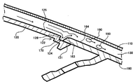
図4、図5に示すように、助手席用のエアバッグ装置140は、インストルメントパネル100に設けられるエアバッグリッド部150と、このエアバッグリッド部150の下方にエアバッグモジュール180が配置されている。   As shown in FIGS. 4 and 5, in the airbag device 140 for the passenger seat, an airbag grid portion 150 provided in the instrument panel 100 and an airbag module 180 are disposed below the airbag grid portion 150. .

インストルメントパネル100は、表皮110と芯材120との間に発泡層130が設けられた3層構造となっている。   The instrument panel 100 has a three-layer structure in which a foam layer 130 is provided between the skin 110 and the core material 120.

エアバッグモジュール180は、上部が開口された金属製のモジュール容器181に図示しないエアバッグ本体と、エアバッグ本体を膨らませるための圧力気体を発生させるインフレータとが収納されている。   The airbag module 180 contains an airbag main body (not shown) and an inflator that generates pressure gas for inflating the airbag main body in a metal module container 181 having an upper opening.

エアバッグリッド部150は、芯材120に形成された開口部121と、開口部121に対して上方から閉鎖可能に取付けられるドア部材160を有している。   The air grid portion 150 includes an opening 121 formed in the core member 120 and a door member 160 attached to the opening 121 so as to be closed from above.

さらに詳細には、芯材120における開口部121の周縁部全周に対し、ドア部材160の厚み分だけ一段低くなった段差部122が設けられ、この段差部122の下段123に対して、ドア部材160が係止固定されている。   More specifically, a step 122 that is one step lower than the entire circumference of the periphery of the opening 121 in the core member 120 is provided by the thickness of the door member 160. The member 160 is locked and fixed.

即ち、段差部122の下段上面124と、これに対応するドア部材160の縁部下面161とがそれぞれ全周に亘って当接し、段差部122に係止されることにより、ドア部材160は、芯材120の一般面125とほぼ面一の状態に配置されている。尚、ドア部材160の内面側(下面)には、エアバッグモジュール180内に配置されているインフレータが動作し、エアバッグ本体が膨張した際に、膨張したエアバッグ本体の押圧力によって、エアバッグ本体膨出用開口を形成可能な開裂溝151が形成されている。   That is, the lower upper surface 124 of the stepped portion 122 and the corresponding edge lower surface 161 of the door member 160 abut each other over the entire circumference and are locked to the stepped portion 122, whereby the door member 160 is The core member 120 is disposed so as to be substantially flush with the general surface 125 of the core member 120. Note that an inflator disposed in the airbag module 180 operates on the inner surface side (lower surface) of the door member 160, and when the airbag body is inflated, the airbag body is compressed by the pressing force of the inflated airbag body. A cleavage groove 151 capable of forming a main body bulge opening is formed.

さらに、図6に示すように、ドア部材160の縁部下面側161から、全周に亘って庇状に外方、かつ下り傾斜しながら延びるシール片162を設け、ドア部材160を芯材120に形成された開口部121に配設する際に、シール片162を芯材120における段差部122の下段上面124に密着させている。   Further, as shown in FIG. 6, a seal piece 162 is provided extending from the edge lower surface side 161 of the door member 160 outwardly like a bowl over the entire circumference while being inclined downward, so that the door member 160 is made of the core material 120. The seal piece 162 is brought into close contact with the lower upper surface 124 of the stepped portion 122 of the core member 120 when being disposed in the opening 121 formed in FIG.

このようなエアバッグリッド部150はインストルメントパネル100と一体に形成される。例えば、予めドア部材160が取付けられた芯材120を発泡型の上型にセットし、下型に予備賦形された表皮110をセットし、その間にウレタンフォーム原料等の液状発泡原料(発泡剤)を注入し、その後、型締めを行い、発泡原料を発泡させることによってエアバッグリッド部150(インストルメントパネル100)が製造されている。   Such an air grid portion 150 is formed integrally with the instrument panel 100. For example, the core material 120 to which the door member 160 is previously attached is set in the upper mold of the foam type, and the skin 110 preliminarily shaped is set in the lower mold, and the liquid foam raw material (foaming agent) such as urethane foam raw material is set between them. ), And then the mold is clamped to foam the foaming raw material, whereby the air bag grid portion 150 (instrument panel 100) is manufactured.

この発泡成形時は、ドア部材160の縁部下面161から庇状に外方へ延びるシール片162を芯材120の開口部121の周縁部の段差部122の下段上面124に密着させることにより、芯材120における開口部121の周縁部の段差部122の下段上面124とドア部材160の縁部下面161との当接部から発泡剤の漏れを防止している。   At the time of foam molding, the seal piece 162 extending outwardly in a bowl shape from the edge lower surface 161 of the door member 160 is brought into close contact with the lower upper surface 124 of the stepped portion 122 at the peripheral edge of the opening 121 of the core member 120. Leakage of the foaming agent is prevented from a contact portion between the lower upper surface 124 of the step 122 at the peripheral edge of the opening 121 in the core member 120 and the edge lower surface 161 of the door member 160.

特開2004−243594号公報JP 2004-243594 A

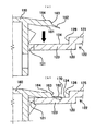
しかしながら、上記エアバッグリッド部構造では、芯材120における開口部121の周縁部全周に対し、ドア部材160の厚み分だけ一段低くなった段差部122を設け、この段差部122の下段上面124に対して、ドア部材160の縁部下面161から、全周に亘って延びるシール片162を設け、ドア部材160を芯材120に形成された開口部121の段差部122に配設する際に、シール片162を芯材120における段差部122の下段上面124に密着させるというシール構造を採用していることから、芯材120における開口部121の段差部122の一般面125(上段)と、ドア部材160の周縁部の上面との間を滑らかな面で形成することができず、溝等の隙間170が形成されてしまう。   However, in the air bag grid part structure, the step part 122 that is one step lower by the thickness of the door member 160 is provided on the entire periphery of the peripheral part of the opening part 121 in the core member 120, and the lower upper surface 124 of the step part 122 is provided. On the other hand, when the seal piece 162 extending over the entire circumference is provided from the edge lower surface 161 of the door member 160 and the door member 160 is disposed in the stepped portion 122 of the opening 121 formed in the core member 120, Since the seal structure in which the seal piece 162 is closely attached to the lower upper surface 124 of the stepped portion 122 in the core member 120 is adopted, the general surface 125 (upper step) of the stepped portion 122 of the opening 121 in the core member 120 and the door A gap between the upper surface of the peripheral portion of the member 160 cannot be formed with a smooth surface, and a gap 170 such as a groove is formed.

このため、図7に示すように、発泡成形時に芯材120の段差部122の縦壁126と、段差部122の下段上面124と、ドア部材160の外周壁163から形成される溝等の隙間170に発泡原料(発泡剤)が流れ込む事により、流れに急激な変化が起こり、乱流が発生し、発泡原料(発泡剤)中に想定外の空気を巻き込むことになり、ボイド190が発生し、そのボイド190を起因とする外観品質不良や触感品質不良が発生するという問題があった。   Therefore, as shown in FIG. 7, a gap such as a groove formed from the vertical wall 126 of the stepped portion 122 of the core member 120, the lower upper surface 124 of the stepped portion 122, and the outer peripheral wall 163 of the door member 160 during foam molding. When the foaming raw material (foaming agent) flows into 170, a rapid change occurs in the flow, turbulence occurs, and unexpected air is entrained in the foaming raw material (foaming agent), and void 190 is generated. There has been a problem that appearance quality defects and tactile quality defects due to the void 190 occur.

本発明は、このような従来技術の技術課題に鑑みてなされたもので、芯材120における開口部121の内周縁部とドア部材160の周縁部との当接部から発泡成形時の発泡原料(発泡剤)の漏れを防止しつつ、かつ芯材120における開口部121の内周縁部の段差部122と、ドア部材160の周縁部との間の溝等の隙間170を起因とするボイド190の発生を抑制することを目的とする。   The present invention has been made in view of such technical problems of the prior art. From the contact portion between the inner peripheral edge portion of the opening 121 and the peripheral edge portion of the door member 160 in the core member 120, the foam raw material at the time of foam molding is provided. A void 190 caused by a gap 170 such as a groove between the step 122 on the inner peripheral edge of the opening 121 and the peripheral edge of the door member 160 while preventing leakage of the foaming agent. It aims at suppressing generation | occurrence | production of this.

上記目的を達成するために、本発明のある態様では、表皮と芯材の間に発泡層が設けられ、前記芯材に内周縁部に段差部を有する開口部を形成し、前記段差部の周壁に対して隙間を有し内側に配設可能な外周壁部を有するドア部材を、前記段差部に上方から前記開口部を閉鎖可能に、かつ段差部の下段上面とドア部材の縁部下面を当接させて取付けられるエアバッグリッド部構造において、前記ドア部材に外周壁部の上面側から外方へ庇状に延びるシール片を形成し、該シール片は、前記ドア部材を前記芯材の開口部の段差部に組付けた際に、前記段差部の周壁と前記ドア部材の外周壁部との間の隙間を覆うと共に、前記シール片の先端側が、前記芯材の一般面に密着していることを特徴としている。   In order to achieve the above object, in one aspect of the present invention, a foamed layer is provided between the skin and the core material, and an opening having a stepped portion is formed in the inner peripheral edge portion of the core material. A door member having an outer peripheral wall portion that has a gap with respect to the peripheral wall and can be disposed on the inside, the opening portion can be closed to the step portion from above, and the lower upper surface of the step portion and the lower surface of the edge of the door member In the air bag grid portion structure that is attached in contact with each other, a seal piece extending outwardly from the upper surface side of the outer peripheral wall portion is formed on the door member, and the seal piece attaches the door member to the core member. When assembled to the stepped portion of the opening, the gap between the peripheral wall of the stepped portion and the outer peripheral wall portion of the door member is covered, and the tip side of the seal piece is in close contact with the general surface of the core member. It is characterized by having.

この態様によれば、芯材における開口部の内周縁部とドア部材の周縁部との当接部から発泡成形時の発泡原料(発泡剤)の漏れを防止しつつ、かつ芯材における開口部の内周縁部の段差部と、ドア部材の周縁部との間の溝の隙間を起因とするボイドの発生を抑制することができる。   According to this aspect, while preventing leakage of the foaming raw material (foaming agent) at the time of foam molding from the contact portion between the inner peripheral edge of the opening in the core and the peripheral edge of the door member, the opening in the core Generation | occurrence | production of the void resulting from the clearance gap of the groove | channel between the level | step-difference part of an inner peripheral part and the peripheral part of a door member can be suppressed.

本発明に係る実施形態のエアバッグリッド部構造の断面図である。It is sectional drawing of the airbag grid part structure of embodiment which concerns on this invention. 図1のドア部材が芯材の開口部の段差部に取付けられる個所の部分拡大図である。It is the elements on larger scale of the location where the door member of FIG. 1 is attached to the level | step-difference part of the opening part of a core material. ドア部材の平面図である。It is a top view of a door member. 従来のインストルメントパネルの正面図である。It is a front view of the conventional instrument panel. 図4のエアバッグリッド部構造の断面図である。It is sectional drawing of the airbag grid part structure of FIG. 従来のドア部材を芯材の段差部に組付ける説明断面図である。It is explanatory sectional drawing which assembles the conventional door member to the level difference part of a core material. 従来のドア部材が芯材の開口部の段差部に取付けられる個所における発泡成形時の部分拡大図である。It is the elements on larger scale at the time of the foam molding in the location where the conventional door member is attached to the level | step-difference part of the opening part of a core material.

(全体)
自動車などの車両における車室内の前部には、インスルメントパネルが設けられている。このインストルメントパネルの助手席側の部分には、助手席用のエアバッグ装置が設けられている。
(The entire)
An instrument panel is provided in the front part of the passenger compartment of a vehicle such as an automobile. A passenger seat airbag device is provided on the passenger seat side of the instrument panel.

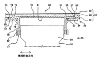
図1に示すように、助手席用のエアバッグ装置50は、インスルメントパネル10に設けられるエアバッグリッド部60と、このエアバッグリッド部60の下方に配置されるエアバッグモジュール90とから構成されている。   As shown in FIG. 1, the airbag device 50 for the passenger seat is composed of an airbag grid part 60 provided in the instrument panel 10 and an airbag module 90 disposed below the airbag grid part 60. Yes.

(インストルメントパネル)
インストルメントパネル10は、表皮20と芯材30との間に発泡層40が設けられた3層構造を有している。
(instrument panel)
The instrument panel 10 has a three-layer structure in which a foam layer 40 is provided between the skin 20 and the core material 30.

(エアバッグモジュール)
また、エアバッグモジュール90は図示しない袋状のエアバッグ本体と、このエアバッグ本体を膨張させるための圧力気体を発生可能なインフレータとを、上端面が開口した金属製のモジュール容器91に収納した構造を有している。このエアバッグモジュール90はその下部をインストルメントパネル10の内部に配設され、図示しない車体側のステアリングメンバに固定されている。
(Airbag module)
The airbag module 90 accommodates a bag-shaped airbag body (not shown) and an inflator capable of generating pressure gas for inflating the airbag body in a metal module container 91 having an open upper end surface. It has a structure. The lower part of the airbag module 90 is disposed inside the instrument panel 10 and is fixed to a steering member on the vehicle body side (not shown).

(エアバッグリッド部)
エアバッグリッド部60は、膨張したエアバッグ本体の押圧力によってエアバッグ本体が膨出する開口を形成可能な開裂溝61が下面側に有している。この開裂溝61は、例えば「H」「U」字状など形状を有している。
(Airbag grid part)
The airbag grid part 60 has a cleavage groove 61 on the lower surface side that can form an opening through which the airbag body bulges due to the pressing force of the inflated airbag body. The cleavage groove 61 has a shape such as “H” or “U” shape.

また、エアバッグリッド部60は、表皮20と芯材30との間に発泡層40が設けられた3層構造となっており、インストルメントパネル10と一体に形成されている。   The airbag grid portion 60 has a three-layer structure in which a foam layer 40 is provided between the skin 20 and the core member 30 and is formed integrally with the instrument panel 10.

そして、エアバッグリッド部60は、芯材30に形成された開口部31に対して上方から閉鎖可能にドア部材70が取付けられた構造となっている。この開口部31およびドア部材70は、平面視した場合に車幅方向に長い矩形状を呈している。開口部31は、エアバッグモジュール90の取付け部に対応する位置に、モジュール容器91の外形形状より多少、大きく形成されている。   The airbag grid part 60 has a structure in which a door member 70 is attached to the opening 31 formed in the core member 30 so as to be closed from above. The opening 31 and the door member 70 have a rectangular shape that is long in the vehicle width direction when seen in a plan view. The opening 31 is formed slightly larger than the outer shape of the module container 91 at a position corresponding to the mounting portion of the airbag module 90.

さらに、開口部31の内周縁部32とドア部材70の縁部下面72との間には、互いに全周に亘って当接可能な当接面が形成されている。   Further, an abutting surface that can abut against each other over the entire circumference is formed between the inner peripheral edge portion 32 of the opening 31 and the edge lower surface 72 of the door member 70.

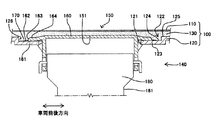
さらに詳細には、芯材30の開口部31の内周縁部32の全周に、芯材30の一般面36に対しドア部材70の厚み分だけ下方へ一段低くなった段差部33を設け、この段差部33の下段34に対してドア部材70が上方から載置され係止固定される。そして、この段差部33の下段上面35と、これに対応するドア部材70の縁部下面72とが全周に亘って当接する当接面とされている。尚、段差部33は、芯材30の一般面36と下段34との間には、縦壁状の周壁37を有している。   More specifically, a step portion 33 is provided on the entire circumference of the inner peripheral edge portion 32 of the opening portion 31 of the core member 30 so as to be one step lower than the general surface 36 of the core member 30 by the thickness of the door member 70, The door member 70 is placed from above and locked to the lower step 34 of the stepped portion 33. The lower upper surface 35 of the stepped portion 33 and the edge lower surface 72 of the door member 70 corresponding to the stepped portion 33 are contact surfaces that contact the entire circumference. The step portion 33 has a vertical wall-shaped peripheral wall 37 between the general surface 36 of the core member 30 and the lower step 34.

(芯材・ドア部材)
芯材30は、ドア部材70に対し相対的に硬質の樹脂、例えば、PP材(ポリプロピレン)等で形成されており、ドア部材70は芯材30に対し相対的に軟質の樹脂、例えば、ゴム系の材料を含んで弾性力のあるTPE材(熱可塑性エラストマー)等で形成されている。これは、PP材は、剛性が高くインストルメントパネル10の芯材30等に一般的によく使用されるが、低温時に衝撃を受けた際に脆性破壊することが知られており、このため、エアバッグリッド部60のドア部材70等には低温時における耐脆性を有する材料、例えばTPE材等が使用されている。
(Core material / door material)
The core member 30 is made of a resin that is relatively hard with respect to the door member 70, such as PP material (polypropylene). The door member 70 is a resin that is relatively soft with respect to the core member 30, such as rubber. It is made of an elastic TPE material (thermoplastic elastomer) or the like including a material of the system. This is because PP material has high rigidity and is generally used for the core material 30 of the instrument panel 10 and the like, but it is known that the material is brittle when subjected to an impact at a low temperature. A material having resistance to brittleness at a low temperature, such as a TPE material, is used for the door member 70 of the airbag grid portion 60 and the like.

ドア部材70の輪郭を形成する外周壁部73は、芯材30の開口部31の段差部33に配置した際に、段差部33を形成する縦壁状の周壁37に対して内側へ若干の隙間80を有して配設可能な大きさに形成されている。これは、芯材30とドア部材70を形成する樹脂材料が異なり、それに伴い夫々の材料の線膨張係数も異なるためであり、温度変化による互いの干渉を回避するためである。   When the outer peripheral wall 73 that forms the contour of the door member 70 is disposed on the stepped portion 33 of the opening 31 of the core member 30, the outer peripheral wall 73 is slightly inward from the vertical wall-shaped peripheral wall 37 that forms the stepped portion 33. It is formed in a size that can be disposed with a gap 80. This is because the resin materials forming the core member 30 and the door member 70 are different, and the linear expansion coefficients of the respective materials are also different accordingly, so as to avoid mutual interference due to temperature changes.

また、上記に、芯材30の開口部31の内周縁部32に、芯材30の一般面36に対しドア部材70の厚み分だけ一段低くなった段差部33が設けられている旨を記載したが、さらに詳細に説明する。本実施形態では、ドア部材70を、芯材30における開口部31の段差部33の下段上面35に載置した際に、ドア部材70の上面74は、芯材30の一般面36より多少高くなるように形成されている。   Further, it is described above that the stepped portion 33 is provided on the inner peripheral edge portion 32 of the opening portion 31 of the core member 30 so as to be one step lower than the general surface 36 of the core member 30 by the thickness of the door member 70. However, this will be described in more detail. In this embodiment, when the door member 70 is placed on the lower upper surface 35 of the stepped portion 33 of the opening 31 in the core member 30, the upper surface 74 of the door member 70 is slightly higher than the general surface 36 of the core member 30. It is formed to become.

そして、ドア部材70の外周壁部73の上面74側から、全周に亘って外方へ庇状に、かつ下り傾斜しながら延びる薄肉のシール片75が形成されている。シール片75の外周壁部73からの外方への長さは、ドア部材70を芯材30に形成された開口部31における段差部33に配設した際に、シール片75の先端が芯材30の一般面36に載置される以上の長さとなっている。また、下り傾斜の度合は、ドア部材70を芯材30に形成された開口部31における段差部33に配設した際に、シール片75が芯材30の一般面36に密着して押圧するような傾斜角度及び肉厚に形成されている。このようにシール片75は芯材30の一般面36に密着させうるのに十分な可撓性を有するように形成されている。   A thin seal piece 75 is formed extending from the upper surface 74 side of the outer peripheral wall portion 73 of the door member 70 outwardly in a bowl shape and while being inclined downward. The outward length of the seal piece 75 from the outer peripheral wall portion 73 is such that when the door member 70 is disposed at the stepped portion 33 in the opening portion 31 formed in the core member 30, the tip of the seal piece 75 is the core. The length is longer than that placed on the general surface 36 of the material 30. In addition, when the door member 70 is disposed at the stepped portion 33 in the opening 31 formed in the core member 30, the degree of the downward inclination is tightly pressed by the seal piece 75 against the general surface 36 of the core member 30. It is formed in such an inclination angle and thickness. As described above, the seal piece 75 is formed so as to have sufficient flexibility to be brought into close contact with the general surface 36 of the core member 30.

また、ドア部材70を、芯材30の開口部31の段差部33に配置した際には、ドア部材70のシール片75が、芯材30における開口部31の内周縁部32の段差部33の周壁37と、ドア部材70の外周壁部73との間に形成される溝等の隙間80を覆うように形成されている。尚、シール片75は、シール片75の基部側から先端側に向かい先細り状に形成したり、シール片75の基部側に可撓性を向上させるために、図示しない溝、スリット等の連続する切欠きを設けてもよい。   Further, when the door member 70 is disposed at the stepped portion 33 of the opening 31 of the core member 30, the seal piece 75 of the door member 70 is stepped 33 at the inner peripheral edge 32 of the opening 31 of the core member 30. Is formed so as to cover a gap 80 such as a groove formed between the peripheral wall 37 and the outer peripheral wall 73 of the door member 70. Note that the seal piece 75 is formed in a tapered shape from the base side to the tip side of the seal piece 75, or a groove, a slit or the like (not shown) is continuous to improve flexibility on the base side of the seal piece 75. A notch may be provided.

また、ドア部材70の下面には、前記した開裂溝61が形成されていると共に、開裂溝61の外側となる位置に角筒状の支持枠77が一体的に形成されている。この支持枠77は、芯材30に組付けられたドア部材70をエアバッグモジュール90のモジュール容器91に連結して、ドア部材70をエアバッグモジュール90に支持させるものである。そのため、支持枠77には、エアバッグモジュール90の前後側面に形成されているフック部92が、係止可能なフック窓部78が設けられ、エアバッグモジュール90のフックが支持枠77の内側からフック窓部78に挿入係止される。   In addition, the cleavage groove 61 described above is formed on the lower surface of the door member 70, and a square cylindrical support frame 77 is integrally formed at a position outside the cleavage groove 61. The support frame 77 connects the door member 70 assembled to the core member 30 to the module container 91 of the airbag module 90 so that the door module 70 is supported by the airbag module 90. Therefore, the support frame 77 is provided with a hook window portion 78 on which the hook portions 92 formed on the front and rear side surfaces of the airbag module 90 can be locked, and the hook of the airbag module 90 is attached from the inside of the support frame 77. The hook window 78 is inserted and locked.

また、支持枠77には、芯材30における開口部31の内周縁部32の段差部33の下段34の裏面に係止される複数個の爪部79を有している。この爪部79の係合により、ドア部材70は芯材30の開口部31に係合固定されている。尚、支持枠77は、芯材30の開口部31を貫挿できる大きさに形成されている。   Further, the support frame 77 has a plurality of claw portions 79 that are engaged with the back surface of the lower step 34 of the step portion 33 of the inner peripheral edge portion 32 of the opening portion 31 in the core member 30. The door member 70 is engaged and fixed to the opening 31 of the core member 30 by the engagement of the claw portion 79. The support frame 77 is formed in a size that allows the opening 31 of the core member 30 to be inserted therethrough.

このようなエアバッグ装置50は、車両が衝突した等の緊急時に、インフレータからの圧力気体によってエアバッグ本体が膨張されると、膨張されたエアバッグ本体は、ドア部材70の裏面側を押圧して開裂溝61を破断してドア部材70およびエアバッグリッド部60を開口させる。さらに、エアバッグ本体は、この開口から車室内乗員側へと膨出して、乗員の頭部がインストルメントパネル10に2次的に当接しないように、乗員の体を保護・拘束する。   In such an airbag device 50, when the airbag body is inflated by the pressure gas from the inflator in an emergency such as a vehicle collision, the inflated airbag body presses the back side of the door member 70. Thus, the cleavage groove 61 is broken to open the door member 70 and the airbag grid portion 60. Further, the airbag main body bulges from the opening toward the passenger in the passenger compartment, and protects and restrains the occupant's body so that the occupant's head does not secondarily contact the instrument panel 10.

次に、この実施形態のエアバッグリッド部構造の作用について説明する。   Next, the operation of the airbag grid part structure of this embodiment will be described.

上記した、このようなエアバッグリッド部60は、インストルメントパネル10と一体に形成され、具体的には、次のように形成される。   The airbag grid portion 60 described above is formed integrally with the instrument panel 10, and specifically, is formed as follows.

まず、芯材30における開口部31の内周縁部32の段差部33の下段上面35に、ドア部材70を上方から載置すると共に、ドア部材70の支持枠77に形成された複数個の爪部79とドア部材70の外周縁71の縁部下面72とにより、芯材30における開口部31の内周縁部32の段差部33の下段34を上下から挟持することにより、ドア部材70を芯材30に固定する。   First, the door member 70 is placed on the lower upper surface 35 of the stepped portion 33 of the inner peripheral edge 32 of the opening 31 in the core member 30, and a plurality of claws formed on the support frame 77 of the door member 70. The lower part 34 of the step part 33 of the inner peripheral edge part 32 of the opening 31 in the core member 30 is sandwiched from above and below by the edge 79 and the edge lower surface 72 of the outer peripheral edge 71 of the door member 70, thereby Fix to the material 30.

この時、ドア部材70のシール片75は、芯材30における開口部31の内周縁部32の段差部33の周壁37と、ドア部材70の外周壁部73との間に形成される溝等の隙間80を覆い、かつシール片75の先端側は、芯材30の一般面36に密着している状態となっている。   At this time, the seal piece 75 of the door member 70 is a groove formed between the peripheral wall 37 of the stepped portion 33 of the inner peripheral edge portion 32 of the opening 31 in the core member 30 and the outer peripheral wall portion 73 of the door member 70. The front end side of the seal piece 75 is in close contact with the general surface 36 of the core member 30.

次ぎに、ドア部材70が固定された芯材30を、図示しない発泡型の、例えば上型にセットし、また、下型に予備賦形された表皮20をセットし、その間にウレタンフォーム原料等の液状発泡原料(発泡剤)を注入し、その後、型締めを行い、発泡原料を発泡させることによってエアバッグリッド部60(インストルメントパネル10)を成形している。   Next, the core member 30 to which the door member 70 is fixed is set in a foaming type (not shown), for example, an upper die, and a skin 20 preliminarily shaped is set in a lower die, and a urethane foam raw material or the like is set therebetween. The air foam grid part 60 (instrument panel 10) is formed by injecting a liquid foam raw material (foaming agent), then performing mold clamping and foaming the foam raw material.

この発泡成形時には、図2に示すように、発泡型内で発泡原料(発泡剤)がドア部材70の外側より流動してくる。しかし、ドア部材70の外周壁部73の上面74側から全周に亘って外方へ庇状に、かつ下り傾斜しながら延びる薄肉のシール片75が、芯材30における開口部31の内周縁部32の段差部33の周壁37と、ドア部材70の外周壁部73との間に形成される溝等の隙間80を覆い、かつシール片75の先端側は芯材30の一般面36と密着状態となっていることから、発泡原料(発泡剤)が、シール片75の先端部の下面と、シール片75の先端部が当接する芯材30の一般面36の間から芯材30開口部31側へ流動することができず、発泡原料(発泡剤)の漏れを防止できる。   At the time of foam molding, as shown in FIG. 2, the foaming material (foaming agent) flows from the outside of the door member 70 in the foaming mold. However, a thin seal piece 75 extending outwardly from the upper surface 74 side of the outer peripheral wall portion 73 of the door member 70 in a bowl shape and while being inclined downward is the inner peripheral edge of the opening 31 in the core member 30. Covering a gap 80 such as a groove formed between the peripheral wall 37 of the stepped portion 33 of the portion 32 and the outer peripheral wall portion 73 of the door member 70, and the front end side of the seal piece 75 is connected to the general surface 36 of the core member 30. Since the foaming raw material (foaming agent) is in the close contact state, the opening of the core member 30 is formed between the lower surface of the tip portion of the seal piece 75 and the general surface 36 of the core member 30 with which the tip portion of the seal piece 75 abuts. It cannot flow to the part 31 side, and leakage of the foaming raw material (foaming agent) can be prevented.

また、シール片75により、芯材30における開口部31の内周縁部32の段差部33の周壁37と、ドア部材70の外周壁部73との間に形成される溝等の隙間80を覆っていることから、発泡原料(発泡剤)が、溝等の隙間80内に流れ込むことがなく、それにより急激な流れの変化が起こらず、乱流も発生しないことから、ボイドの発生を抑制することができる。   Further, the seal piece 75 covers a gap 80 such as a groove formed between the peripheral wall 37 of the stepped portion 33 of the inner peripheral edge 32 of the opening 31 in the core member 30 and the outer peripheral wall 73 of the door member 70. Therefore, the foaming raw material (foaming agent) does not flow into the gap 80 such as a groove, so that a rapid flow change does not occur and turbulence does not occur, thereby suppressing the generation of voids. be able to.

(変形例)
なお、上記した本実施形態では、ドア部材70のシール片75をドア部材70の外周壁部73の全周に設けたが、シール片75を全周に設けると、シール片75の板厚とドア部材70の周縁部との板厚の違いにより、成形収縮率が異なり、シール片75が波打ち変形を起こすことが予測される。詳細には、ドア部材70の周縁部は、板厚が厚く、樹脂が固化するまでに時間がかかり、収縮率が大きく、また、シール片75は、板厚が薄く、冷却による固化も早く、収縮率が小さいためである。シール片75が波打ち変形すると、シール片75の先端部が当接する芯材30の一般面36との間に隙間80が発生し、発泡成形時に発泡原料(発泡剤)の漏れが発生してしまう。
(Modification)
In the above-described embodiment, the seal piece 75 of the door member 70 is provided on the entire circumference of the outer peripheral wall portion 73 of the door member 70. However, when the seal piece 75 is provided on the entire circumference, Depending on the difference in plate thickness with the peripheral edge of the door member 70, the molding shrinkage rate is different, and it is predicted that the seal piece 75 will be wavy. Specifically, the peripheral portion of the door member 70 has a large plate thickness, it takes time until the resin is solidified, the shrinkage rate is large, and the seal piece 75 has a thin plate thickness and is quickly solidified by cooling. This is because the shrinkage rate is small. When the seal piece 75 is wave-deformed, a gap 80 is generated between the seal piece 75 and the general surface 36 of the core member 30 with which the tip of the seal piece 75 comes into contact, and leakage of the foaming material (foaming agent) occurs during foam molding. .

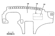
そこで、シール片75の波打ち変形を防止するために、図3に示すように、シール片75にシール片75の先端側からシール片75の基部となるドア部材70の外周縁71部側へ向かうスリット、溝等の切欠き76を形成し、収縮率の影響を緩和させてもよい。尚、図3に示した切欠き76部は、理解を容易にするために、過度に大きく記載したものであり、実際のドア部材70の大きさに対する切欠き76の大きさとは異なっている。   Therefore, in order to prevent the wavy deformation of the seal piece 75, as shown in FIG. 3, the seal piece 75 moves from the distal end side of the seal piece 75 toward the outer peripheral edge 71 portion side of the door member 70 that becomes the base portion of the seal piece 75. A notch 76 such as a slit or groove may be formed to reduce the influence of the shrinkage rate. The notch 76 shown in FIG. 3 is described excessively large for easy understanding, and is different from the size of the notch 76 with respect to the actual size of the door member 70.

尚、シール片75に切欠き76を設けた事により発泡成形時に発泡原料(発泡剤)の漏れが懸念される。そこで、シール片75に形成する切欠き76位置は、次のような個所に設ける。   In addition, since the notch 76 is provided in the seal piece 75, there is a concern that the foaming material (foaming agent) may leak during foam molding. Therefore, the position of the notch 76 formed in the seal piece 75 is provided at the following location.

例えば、車幅方向に長い矩形状のドア部材70の長辺側と短片側のどちらか一方の外周縁71を他方側の外周縁71に対し、芯材30側の段差部33の下段面に強く密着させるようにする。そして、強く密着させた辺側、即ち一方側に形成されるシール片75の辺中央部に切り欠きを設ける。   For example, the outer peripheral edge 71 on either the long side or the short side of the rectangular door member 70 that is long in the vehicle width direction is set on the lower step surface of the step portion 33 on the core member 30 side with respect to the outer peripheral edge 71 on the other side. Try to make it tight. Then, a notch is provided in the side central portion of the seal piece 75 formed on the side that is firmly adhered, that is, one side.

その強く密着させる構造としては、例えば、次のような構造とする。ドア部材70の支持枠77には、複数個の爪部79を有しており、この爪部79とドア部材70の外周縁71の縁部下面72とにより芯材30における開口部31の内周縁部32の段差部33の下段34を上下から挟持することにより、ドア部材70を芯材30に保持している。そこで、ドア部材70の長辺側または、短辺側のどちらか一方の側の爪部79の形成するピッチを短くする。それにより、爪部79のピッチを短くした側のドア部材70の外周縁71の縁部下面72と芯材30の段差部33の下段上面35との間の密着力が向上する。そこで爪部79のピッチを短くした側の対向する辺縁のシール片75の略中央部に切欠き76を設ける。本実施形態では、長辺側のシール片75に切欠き76を設けている。   For example, the following structure is used as the structure to be strongly adhered. The support frame 77 of the door member 70 has a plurality of claw portions 79, and the claw portions 79 and the edge lower surface 72 of the outer peripheral edge 71 of the door member 70, the inside of the opening 31 in the core member 30. The door member 70 is held on the core member 30 by sandwiching the lower step 34 of the stepped portion 33 of the peripheral edge portion 32 from above and below. Therefore, the pitch formed by the claw portions 79 on either the long side or the short side of the door member 70 is shortened. Thereby, the adhesive force between the edge lower surface 72 of the outer peripheral edge 71 of the door member 70 on the side where the pitch of the claw portions 79 is shortened and the lower upper surface 35 of the stepped portion 33 of the core member 30 is improved. Therefore, a notch 76 is provided in a substantially central portion of the seal piece 75 on the opposite edge on the side where the pitch of the claw portions 79 is shortened. In this embodiment, a notch 76 is provided in the long side seal piece 75.

また、ドア部材70の長辺側と短片側のどちらか一方の外周縁71を、芯材30側の段差部33の下段面に強く密着させる他の方法として、ドア部材70を成形する時に、ドア部材70の長辺側または短辺側の外周縁71の一方を、若干、芯材30側へ強干渉するように撓ませて、撓ませた側のシール片75に切欠き76を設けてもよい。ドア部材70の長辺側または短辺側の外周縁71の一方を芯材30側へ強干渉するように撓ませることにより、撓ませた側のドア部材70の外周縁71の下面を芯材30側の段差部33の下段面に強く密着させることができ、ドア部材70の外周縁71の下面と芯材30の段差部33の下段上面35との間で十分なシール性を得るができる。   Further, as another method for strongly adhering the outer peripheral edge 71 of either the long side or the short piece side of the door member 70 to the lower step surface of the step portion 33 on the core member 30 side, when molding the door member 70, One of the outer peripheral edges 71 on the long side or the short side of the door member 70 is slightly bent so as to strongly interfere with the core member 30 side, and a notch 76 is provided in the bent seal piece 75. Also good. The bottom surface of the outer peripheral edge 71 of the door member 70 on the bent side is made to be a core material by bending one of the outer peripheral edges 71 on the long side or the short side of the door member 70 so as to strongly interfere with the core material 30 side. The lower step surface 33 of the step portion 33 on the 30 side can be strongly adhered, and a sufficient sealing property can be obtained between the lower surface of the outer peripheral edge 71 of the door member 70 and the lower upper surface 35 of the step portion 33 of the core member 30. .

尚、シール片75に切欠き76を設けることにより、発泡成形時にシール片75の切欠き76から発泡原料(発泡剤)が多少漏れたとしても、芯材30の段差部33の下段上面35にドア部材70の縁部下面72が十分なシール性を有して密着しているため、芯材30の開口部31内まで発泡原料(発泡剤)が漏れることはない。また、発泡原料(発泡剤)がシール片75の切欠き76を介して溝等の隙間80内に流れ込み、急激な流れの変化を起こすことが考えられるが、切欠き76が形成される個所は、矩形状のドア部材70の長辺側と短片側のどちらか一方の対向する片側に各1つ程度設けるに留まるため、多少ボイドが発生したとしても外観品質不良や触感品質不良に至るほどのものでなく、従来のエアバッグリッド部構造に対しボイドの発生を大きく抑制することができる。   In addition, by providing the notch 76 in the seal piece 75, even if the foaming material (foaming agent) leaks from the notch 76 of the seal piece 75 during foam molding, the lower upper surface 35 of the step portion 33 of the core member 30 is provided. Since the edge lower surface 72 of the door member 70 is in close contact with a sufficient sealing property, the foaming material (foaming agent) does not leak into the opening 31 of the core member 30. Further, it is conceivable that the foaming raw material (foaming agent) flows into the gap 80 such as a groove through the notch 76 of the seal piece 75 and causes a sudden flow change. In addition, since only one of each of the long side and the short side of the rectangular door member 70 is provided to face each other, even if some voids are generated, the appearance quality and the tactile quality are poor. However, the generation of voids can be greatly suppressed compared to the conventional air bag grid part structure.

尚、スリット・溝等の切欠き76付きシール片75を有するドア部材70を成形する際に、成形品状態では、スリット・溝等の切欠き76をゼロタッチ(切欠き76の隙間がゼロ)となるように、収縮率の差異分を金型に折込んで成形してもよい。本構造によれば、成形後の状態では切欠き76がゼロタッチ(切欠き76の隙間がゼロ)となっているため、発泡成形時にシール片75の切欠き76から発泡原料(発泡剤)が漏れることがない。   When molding the door member 70 having the seal piece 75 with the notch 76 such as a slit / groove, in the molded product state, the notch 76 such as the slit / groove is zero-touched (the gap between the notches 76 is zero). As described above, the difference in shrinkage rate may be folded into a mold. According to this structure, since the notch 76 is zero-touched (the gap between the notches 76 is zero) after molding, the foaming material (foaming agent) leaks from the notch 76 of the seal piece 75 during foam molding. There is nothing.

20 表皮
30 芯材
31 開口部
32 内周縁部
33 段差部
35 下段上面
36 一般面
37 周壁
40 発泡層
70 ドア部材
72 縁部下面
73 外周壁部
74 上面
75 シール片
80 隙間
20 Skin 30 Core 31 Opening 32 Inner peripheral edge 33 Stepped portion 35 Lower upper surface 36 General surface 37 Peripheral wall 40 Foamed layer 70 Door member 72 Edge lower surface 73 Outer peripheral wall 74 Upper surface 75 Sealing piece 80 Gap

Claims (1)

表皮と芯材の間に発泡層が設けられ、
前記芯材に内周縁部に段差部を有する開口部を形成し、
前記段差部の周壁に対して隙間を有し内側に配設可能な外周壁部を有するドア部材を、
前記段差部に上方から前記開口部を閉鎖可能に、
かつ段差部の下段上面とドア部材の縁部下面を当接させて取付けられる
エアバッグリッド部構造において、
前記ドア部材に外周壁部の上面側から外方へ庇状に延びるシール片を形成し、
該シール片は、前記ドア部材を前記芯材の開口部の段差部に組付けた際に、
前記段差部の周壁と前記ドア部材の外周壁部との間の隙間を覆うと共に、
前記シール片の先端側が、前記芯材の一般面に密着していることを特徴とするエアバッグリッド部構造。
A foam layer is provided between the skin and the core material,
Forming an opening having a stepped portion on the inner peripheral edge of the core;
A door member having an outer peripheral wall portion that can be disposed on the inner side with a gap with respect to the peripheral wall of the stepped portion;
The opening can be closed to the stepped portion from above.
And in the air bag grid structure that is mounted by contacting the lower upper surface of the stepped portion and the lower surface of the edge of the door member,
Forming a seal piece extending outwardly from the upper surface side of the outer peripheral wall portion in the door member,
When the seal piece is assembled to the stepped portion of the opening of the core member,
Covering the gap between the peripheral wall of the stepped portion and the outer peripheral wall portion of the door member,
The airbag grid part structure, wherein a tip end side of the seal piece is in close contact with the general surface of the core member.
JP2011112934A 2011-05-20 2011-05-20 Airbag lid part structure Withdrawn JP2012240560A (en)

Priority Applications (1)

Application Number Priority Date Filing Date Title
JP2011112934A JP2012240560A (en) 2011-05-20 2011-05-20 Airbag lid part structure

Applications Claiming Priority (1)

Application Number Priority Date Filing Date Title
JP2011112934A JP2012240560A (en) 2011-05-20 2011-05-20 Airbag lid part structure

Publications (1)

Publication Number Publication Date
JP2012240560A true JP2012240560A (en) 2012-12-10

Family

ID=47462703

Family Applications (1)

Application Number Title Priority Date Filing Date
JP2011112934A Withdrawn JP2012240560A (en) 2011-05-20 2011-05-20 Airbag lid part structure

Country Status (1)

Country Link
JP (1) JP2012240560A (en)

Cited By (1)

* Cited by examiner, † Cited by third party
Publication number Priority date Publication date Assignee Title
US9409541B2 (en) 2013-12-04 2016-08-09 Faurecia Interieur Industrie Interior trim part for a motor vehicle comprising an airbag door

Cited By (1)

* Cited by examiner, † Cited by third party
Publication number Priority date Publication date Assignee Title
US9409541B2 (en) 2013-12-04 2016-08-09 Faurecia Interieur Industrie Interior trim part for a motor vehicle comprising an airbag door

Similar Documents

Publication Publication Date Title
JP6073610B2 (en) Engine cover
JP5171032B2 (en) instrument panel
JP2007168729A (en) Resin panel and vehicle door
WO2008018614A1 (en) Interior finish panel and injection molding method
JP2010069854A (en) Molded member with foam
JP4790332B2 (en) Resin molded body
US20090313929A1 (en) Extrusion-molded product having a core material
JP2013256176A (en) Door hole seal structure
JP6674928B2 (en) Foam molding method and foam molded article
JP2012240560A (en) Airbag lid part structure
JP4281046B2 (en) Molded part with foam
JP5808942B2 (en) Method for manufacturing shock absorbing pad and shock absorbing pad
JP4482439B2 (en) Plastic molded product
JP2002052548A (en) Skin seal structure of foamed molded product with skin
JP4337030B2 (en) Seal structure of foamed molded part with skin
JP2004175221A (en) Door weather strip for automobile
JP2015205446A (en) Foamed molding
JP2014128890A (en) Seal structure
JP5953604B2 (en) Foam molded product and method for producing the same
CN111252026B (en) Airbag chute with integral seal
JP2006008084A (en) Vehicle interior member
JP4051679B2 (en) Seal structure for vehicle interior parts
JP4850555B2 (en) Molding method of resin molding
JP4651354B2 (en) Method for producing foamed molded member with skin
JP4399664B2 (en) Manufacturing method of epidermis

Legal Events

Date Code Title Description
A300 Withdrawal of application because of no request for examination

Free format text: JAPANESE INTERMEDIATE CODE: A300

Effective date: 20140805