JP2012236246A - Robot hand, and robot - Google Patents
Robot hand, and robot Download PDFInfo
- Publication number
- JP2012236246A JP2012236246A JP2011105925A JP2011105925A JP2012236246A JP 2012236246 A JP2012236246 A JP 2012236246A JP 2011105925 A JP2011105925 A JP 2011105925A JP 2011105925 A JP2011105925 A JP 2011105925A JP 2012236246 A JP2012236246 A JP 2012236246A
- Authority
- JP
- Japan
- Prior art keywords
- screw
- robot hand
- bit tool
- robot
- finger
- Prior art date
- Legal status (The legal status is an assumption and is not a legal conclusion. Google has not performed a legal analysis and makes no representation as to the accuracy of the status listed.)
- Withdrawn
Links
Images


Abstract
Description
本発明は、対象物を掴むことが可能なロボットハンドに関する。 The present invention relates to a robot hand capable of grasping an object.
従来から工業製品の製造現場では、溶接や塗装などの作業を行うロボットが広く使用さ
れている。また、今日では、大きさや形状の異なる種々の対象物を把持可能なロボットハ
ンドを搭載し、製品の組立作業を行うロボットも提案されている(特許文献1)。
Conventionally, robots that perform operations such as welding and painting have been widely used in industrial product manufacturing sites. In addition, a robot that carries a product assembling work by mounting a robot hand capable of gripping various objects of different sizes and shapes has been proposed today (Patent Document 1).
組立作業で組み立てられた部品は、ネジ締めによって固定されることが一般的である。
従って、組立作業を行うロボットに搭載されるロボットハンドは、種々の対象物を把持し
て部品の組み立てを行うだけでなく、組み立てた部品のネジ締めを実行可能であることが
、作業効率を向上させる点から望ましい。
In general, parts assembled in an assembly operation are fixed by screw tightening.
Therefore, the robot hand mounted on the robot that performs the assembly work not only grips various objects and assembles parts, but also can execute screw tightening of the assembled parts, improving work efficiency. It is desirable from the point of making it.
しかし、部品をネジ締めする作業は、ネジ穴に対してネジが正しい姿勢に保たれるよう
にネジを把持しつつ、適度な力でネジをネジ穴に押し付けながら回転させなければならな
い複雑な作業である。このため、組立作業を行うロボットハンドがネジ締めを行うことは
困難であるという問題があった。また、ネジ締め作業に限らず、対象物を把持した状態で
、対象物を把持する作業とは異なる作業を行う場合にも同様な問題が生じ得る。
However, the work of tightening the parts is a complicated work that requires rotating the screw while pressing the screw against the screw hole with an appropriate force while holding the screw so that the screw is kept in the correct posture with respect to the screw hole. It is. For this reason, there is a problem that it is difficult for the robot hand performing the assembly work to perform the screw tightening. In addition to the screw tightening operation, the same problem may occur when an operation different from the operation of gripping the object is performed while the object is gripped.
この発明は、従来の技術が有する上述した課題の少なくとも一部を解決するためになさ
れたものであり、対象物を把持しながら、対象物を把持する作業とは異なる作業を実行可
能なロボットハンドを提供することを目的とする。
The present invention has been made to solve at least a part of the above-described problems of the prior art, and is a robot hand capable of performing a task different from a task of gripping an object while gripping the object. The purpose is to provide.
上述した課題の少なくとも一部を解決するために、本発明のロボットハンドは次の構成
を採用した。すなわち、対象物を把持する複数の指部と、前記複数の指部が取り付けられ
た掌部と、前記掌部から立設されたビット工具とを備え、前記複数の指部は、前記対象物
を前記ビット工具の軸線上で把持し、前記ビット工具は、前記軸線の方向に摺動可能に設
けられていることを特徴とする。
In order to solve at least a part of the problems described above, the robot hand of the present invention employs the following configuration. That is, a plurality of finger parts for gripping an object, a palm part to which the plurality of finger parts are attached, and a bit tool erected from the palm part, wherein the plurality of finger parts are the object Is held on the axis of the bit tool, and the bit tool is slidable in the direction of the axis.
このような構成を有する本発明のロボットハンドにおいては、複数の指部によって対象
物を把持して組立作業を行う。また、対象物は、掌部から立設されたビット工具の軸線上
に把持されるようになっており、ビット工具は軸線の方向に摺動可能に設けられている。
ここで、「ビット工具」とは、ロボットハンドが対象物を把持する機能とは異なる単一の
機能を実現するための工具である。ビット工具の大きさは、指部材の長さよりも短く、且
つロボットハンドが対象物を把持する動作を妨げない大きさに設定されており、各種のネ
ジのネジ締めや、溶接などの機能を実現することができる。この様なビット工具の具体例
としては、プラスネジやマイナスネジ用のドライバーの先端形状や六角レンチ、ソケット
、あるいは溶接用トーチなどが挙げられる。
In the robot hand of the present invention having such a configuration, an assembly work is performed by gripping an object with a plurality of fingers. The object is gripped on the axis of the bit tool standing from the palm, and the bit tool is slidable in the direction of the axis.
Here, the “bit tool” is a tool for realizing a single function different from the function of the robot hand holding the object. The size of the bit tool is shorter than the length of the finger member and is set to a size that does not hinder the robot hand from gripping the object, realizing various screw tightening and welding functions. can do. Specific examples of such a bit tool include a tip shape of a screwdriver for a plus screw or a minus screw, a hexagon wrench, a socket, or a welding torch.
このようなロボットハンドによれば、複数の指部によって対象物を把持した状態で、把
持した対象物の位置までビット工具を摺動させることができる。従って、ビット工具を動
作させることにより、ロボットハンドで対象物を把持しながら、対象物を把持する作業と
は異なる作業を行うことが可能となる。
According to such a robot hand, the bit tool can be slid to the position of the grasped object while the object is grasped by the plurality of finger portions. Therefore, by operating the bit tool, it is possible to perform an operation different from the operation of grasping the object while grasping the object with the robot hand.
また、上述した本発明のロボットハンドにおいては、掌部をビット工具の軸線回りに回
転可能に設けることとしてもよい。
In the robot hand of the present invention described above, the palm portion may be provided so as to be rotatable around the axis of the bit tool.
このようなロボットハンドによれば、ロボットハンドの指部でネジなどの対象物を把持
したまま、ビット工具を軸線の方向に摺動させて対象物に嵌合させ、この状態で掌部とと
もにビット工具を回転させることができる。こうすれば、指部によってネジをネジ穴に対
して正しい姿勢に保ちながらネジを回転させることができるので、複雑なネジ締めの作業
をロボットハンドによって簡単に行うことが可能となる。さらに、ビット工具をネジと当
接した状態で回転させることで、ビット工具がネジの頭と嵌合し、その結果十分なトルク
でネジを回転させることができ、ネジを最後まで締め付けることができる。
According to such a robot hand, while holding the object such as a screw with the finger part of the robot hand, the bit tool is slid in the direction of the axis to be fitted to the object, and in this state, the bit is moved together with the palm part. The tool can be rotated. In this way, the screw can be rotated while keeping the screw in the correct posture with respect to the screw hole by the finger portion, and therefore it is possible to easily perform a complicated screw tightening operation with the robot hand. Furthermore, by rotating the bit tool in contact with the screw, the bit tool can be fitted with the head of the screw, so that the screw can be rotated with sufficient torque, and the screw can be tightened to the end. .
また、上述した本発明のロボットハンドにおいては、ビット工具を軸線回りに回転させ
る回転部を掌部に設けておき、回転部を介してビット工具を掌部に設けることとしてもよ
い。
Further, in the robot hand of the present invention described above, a rotating part that rotates the bit tool about the axis may be provided in the palm part, and the bit tool may be provided in the palm part via the rotating part.
回転部によってビット工具を回転させることとすれば、ネジ締めを行う際に、掌部や掌
部に取り付けられた複数の指部は回転させずにビット工具を回転させることができる。こ
うすれば、指部や掌部が回転するスペースが確保できないような狭い作業空間でネジ締め
を行う場合でも、ロボットハンドでネジ締めを行うことが可能となる。
If the bit tool is rotated by the rotating portion, the bit tool can be rotated without rotating the palm portion or the plurality of finger portions attached to the palm portion when performing screw tightening. In this way, even when screw tightening is performed in a narrow work space where a space for rotating the finger part and palm part cannot be secured, it is possible to perform screw tightening with the robot hand.
また、上述した本発明のロボットハンドは、様々な大きさや形状の対象物を把持して組
立作業に適用可能であるのみならず、組み立てた対象物のネジ締めを行うことができる。
従って、これら本発明のロボットハンドを用いてロボットを構成すれば、組立作業を効率
よく実行可能なロボットを構成することが可能となる。
In addition, the robot hand of the present invention described above can be applied to assembly work by grasping objects of various sizes and shapes, and can also screw the assembled object.
Therefore, if a robot is configured using these robot hands of the present invention, it is possible to configure a robot that can perform assembly work efficiently.
以下では、上述した本願発明の内容を明確にするために、次のような順序に従って実施
例を説明する。
A.本実施例のロボットハンドの構造:
B.本実施例のロボットハンドのネジ締め動作:
C.変形例:
C−1.第1変形例:
C−2.第2変形例:
C−3.第3変形例:
C−4.第4変形例:
Hereinafter, in order to clarify the contents of the present invention described above, examples will be described in the following order.
A. The structure of the robot hand of this embodiment:
B. Screw tightening operation of the robot hand of this embodiment:
C. Variations:
C-1. First modification:
C-2. Second modification:
C-3. Third modification:
C-4. Fourth modification:
A.本実施例のロボットハンドの構造 :
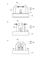
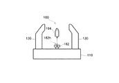
図1は、本実施例のロボットハンド100の構造を示した説明図である。図示されるよ
うに本実施例のロボットハンド100は、ロボットハンド100の土台部分を構成する掌
部材110(掌部)や、掌部材110に取り付けられた2つの指部材120,130(指
部)や、掌部材110の中央の位置に設けられたネジ締め機構160などから構成されて
いる。
A. The structure of the robot hand of this embodiment:
FIG. 1 is an explanatory diagram showing the structure of the
指部材120,130は、紙面上で掌部材110の左右の端付近からそれぞれ立設され
ている。これら指部材120,130は、掌部材110の内部の機構によって、指部材1
20,130の付け根の位置が互いに接近あるいは離間する方向に移動可能となっている
。このため、指部材の付け根の位置を離間させることで、図1(a)に示されるように、
指部材120と指部材130との間の距離が大きくなり、指部材の付け根の位置を接近さ
せることで、図1(b)に示されるように、指部材120と指部材130との間の距離が
小さくなるようになっている。
The
The
As the distance between the
また、掌部材110の中央に設けられたネジ締め機構160は、掌部材110の中心位
置から立設されて、先端に台座が設けられた略円柱形状の支持部材162や、支持部材1
62の台座に固定されるビット工具164などから構成される。尚、ビット工具164と
は、ロボットハンド100が対象物を把持する機能とは別の単機能を実現する専用工具で
あり、長さが指部材120,130の長さよりも短く、且つロボットハンド100が対象
物を把持する動作を妨げない大きさの工具である。ビット工具164が実現する機能には
、各種のネジのネジ締めを行う機能や、溶接作業を行う機能などとすることができる。従
って、ビット工具164の具体例としては、プラスネジやマイナスネジ用のドライバーの
先端形状や六角レンチ、ソケット、あるいは溶接用トーチなどが挙げられる。本実施例で
は、図1に示されているように、ビット工具164にプラスネジ用のドライバーの先端形
状が用いられている。
The
It consists of a
支持部材162は、掌部材110の内部の移動機構(図示せず)によって紙面上で上下
の方向に移動可能となっており、これによりビット工具164を指部材120,130の
根元側と先端側との間で上下に移動させることが可能となっている。図1(c)には、支
持部材162によってビット工具164が指部材120,130の先端付近まで移動させ
たときの様子が示されている。
The
このような本実施例のロボットハンド100では、掌部材110に設けられた左右の指
部材120,130の間隔を大きくしたり小さくしたりすることで、把持しようとする対
象物の大きさや形状に合わせて指部材の間の距離を変更することができる。従って、ロボ
ットハンド100をロボットに搭載すれば、様々な部品を把持して工業製品の組立作業を
行うことが可能である。また、本実施例のロボットハンド100は、部品の組立作業を行
うだけでなく、上述したネジ締め機構160を用いて部品のネジ締めを行うことが可能と
なっている。
In the
B.本実施例のロボットハンドのネジ締め動作 :
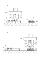
図2は、本実施例のロボットハンド100がネジ締めを行う様子を示した説明図である
。尚、図2には、ロボットハンド100が行うネジ締め作業の前半部分が示されている。
ロボットハンド100がネジ締めを行う場合には、先ず、図2(a)に示されるように、
ロボットハンド100の指部材120,130の先端をホルダーHに保持されたネジSの
頭の位置まで移動させ、この状態で指部材120,130の間隔を狭めてネジSの頭を把
持する。こうすると、ネジSはロボットハンド100の中心軸上(すなわちビット工具1
64の軸線上)に把持される。このようにネジSを把持したら、図2(b)に示されるよ
うに、ロボットハンド100をネジ締めを行う対象物W1,W2の位置まで移動させて、
ネジSの先端をネジ穴Shに取り付ける。
B. Screw tightening operation of the robot hand of this embodiment:
FIG. 2 is an explanatory diagram showing a state in which the
When the
The tips of the
(On 64 axes). When the screw S is gripped in this way, as shown in FIG. 2B, the
The tip of the screw S is attached to the screw hole Sh.
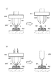
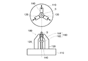
図3は、ロボットハンド100が行うネジ締め作業の後半を示した説明図である。ロボ
ットハンド100で把持したネジSの先端を対象物のネジ穴Shに取り付けたら、図3(
a)に示されるように、掌部材110内の移動機構(図示せず)を駆動して、ビット工具
164を指部材120,130の先端の方向に移動させる。前述したように、ネジSはビ
ット工具164の軸線上に把持されている。また、指部材120,130はネジSの頭の
所定の位置を掴むようになっており、これにより、ビット工具164の先端形状を指先側
に延長した先に、ちょうど把持したネジSの頭の溝がくるようになっている。従って、ビ
ット工具164を移動させると、ビット工具164の先端形状とネジSの頭の溝とが嵌合
した状態となる。
FIG. 3 is an explanatory diagram showing the second half of the screw tightening operation performed by the
As shown in a), a moving mechanism (not shown) in the
このようにビット工具164とネジSの頭の溝とを嵌合させたら、図3(b)に示され
るように、掌部材110内のモーター(図示せず)を回転させることにより、ロボットハ
ンド100の全体を回転させる。こうすると、ネジSが回転してネジ穴Shに挿入されて
いくので、挿入された距離の分ずつロボットハンド100をネジ穴Shの方向に移動させ
ながら回転させることで、ネジ締めを行う。
When the
以上のような本実施例のロボットハンド100によれば、組立作業を行うだけでなく、
組み立てた部品のネジ締め作業を行うことができる。ここで、ネジ締めは工業製品の組立
時には一般的に行われる作業であるが、ロボットハンドがネジ締めを行うことは必ずしも
容易なことではない。
According to the
The assembled parts can be screwed. Here, screw tightening is a work generally performed when assembling industrial products, but it is not always easy for a robot hand to perform screw tightening.
図4は、参考として、従来のロボットハンドを用いてネジ締め作業を行う様子を示した
説明図である。図示した従来のロボットハンド200では、掌部材210に2つの指部材
220,230が取り付けられており、指部材220と指部材230とが互いに接近ある
いは離間可能に設けられている。このようなロボットハンド200を用いてネジ締めを行
う場合、図4(a)に示されるように、指部材220,230によってネジSを把持し、
ネジSを対象物W1,W2のネジ穴Shの位置まで移動させる。その後はドライバーを用
いてネジ締めを行うのであるが、その為にはロボットハンド200を別の位置に移動させ
る必要があるので、ネジSが倒れてしまってネジ締めを行うことはできなくなる。
FIG. 4 is an explanatory view showing a state in which a screw tightening operation is performed using a conventional robot hand as a reference. In the illustrated
The screw S is moved to the position of the screw hole Sh of the objects W1 and W2. After that, the screw is tightened by using a screwdriver. For that purpose, the
また、図4(b)に示されるように、ロボットハンド200で把持したネジSをネジ穴
Shの位置に移動させた状態で、ロボットハンド200の全体を回転させてネジ締めを行
うことも考えられる。しかし、ネジ締めの最後にネジSを部品に締め付ける場合には比較
的大きなトルクが必要となるので、単にネジを指部材220,230によって把持してい
る状態では十分にネジを締め付けることができない。従って、結局は図4(b)に示すよ
うにドライバー300などを用いて仕上げのネジ締めを行うことが必要となってしまう。
Further, as shown in FIG. 4B, it is also possible to perform screw tightening by rotating the
これに対して、本実施例のロボットハンド100では、図3に示したように、ネジ締め
を行っている間は指部材120,130によってネジSを正しい姿勢に保つことができ、
且つビット工具164によってネジSをネジ穴Shに押しつけながら回転させることで十
分なトルク得ることができる。その結果、複雑なネジ締めの作業を、ロボットハンド10
0によって簡単に実行することが可能である。
On the other hand, in the
A sufficient torque can be obtained by rotating the screw S while pressing it against the screw hole Sh by the
It can be easily executed by 0.
また、ロボットハンド100によって把持したネジSの先端をネジ穴Shの位置まで移
動させたら、ロボットハンド100を回転させることで直ちにネジ締めの作業を開始する
ことができる。従って、ネジ締めにかかる時間を短縮することができ、その結果、製品の
組立時間を短縮することが可能である。さらに、本実施例のロボットハンド100では、
ネジ締めを行うにあたり、ビット工具164を指部材120,130の根元から先端の方
向に移動させる動作や、掌部材110を回転させる動作など、簡単な動作を行っているに
過ぎない。従って、ロボットハンド100でネジ締めを行うこととしても、ロボットハン
ド100の制御が複雑となることもない。加えて、対象物を把持する指部材120,13
0を2本とすることで、ロボットハンド100の構造を簡単にすることができる。
When the tip of the screw S gripped by the
In performing the screw tightening, simple operations such as an operation of moving the
By setting 2 to 0, the structure of the
C.変形例 :
上述した実施例には、いくつかの変形例が考えられる。以下では、これらの変形例につ
いて簡単に説明する。尚、以下に説明する変形例において、上述した実施例と同様の構成
部分については、実施例と同様の符号を付し、その詳細な説明を省略する。
C. Modified example:
Several modifications can be considered in the embodiment described above. Hereinafter, these modified examples will be briefly described. Note that, in the modification described below, the same components as those in the above-described embodiment are denoted by the same reference numerals as those in the embodiment, and detailed description thereof is omitted.
C−1.第1変形例 :
上述した実施例のロボットハンド100では、指部材120,130でネジSを把持し
た状態で、ロボットハンド100の全体を回転することによってネジ締めを行うものと説
明した。しかし、ネジ締めを行う場合には、指部材120,130は回転させずに、ビッ
ト工具164を回転させることとしてもよい。
C-1. First modification:
In the
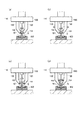
図5は、第1変形例のロボットハンド100によってネジ締めを行う様子を示した説明
図である。図示した第1変形例のロボットハンド100においても、ロボットハンド10
0によって把持したネジSをネジ穴Shに挿入し、ビット工具164の先端をネジSの頭
に嵌合させるまでの動作は、前述した実施例のロボットハンド100が行う動作と同様で
ある(図3を参照)。一方、ビット工具164の先端をネジSの頭に嵌合させた後は、図
5(b)に示されるように、ビット工具164でネジSをネジ穴Shの方向に軽く押し付
けた状態で、指部材120,130を少し離間させる。これにより、ビット工具164で
ネジSを回転させたときにネジSと指部材120,130の間に摩擦が生ずることを抑制
する。また、ネジSはビット工具164によってネジ穴Shに軽く押し付けられているの
で、指部材120,130を少し離間させたとしても、これによってネジSの姿勢が傾い
てしまうこともない。
FIG. 5 is an explanatory view showing a state where screws are tightened by the
The operation until the screw S gripped by 0 is inserted into the screw hole Sh and the tip of the
こうして指部材120,130を少し離間させたら、図5(c)に示されるように、指
部材120,130を少しネジ穴Shの方向に移動させる。これは、ビット工具164を
回転させてネジ締めを行った場合に、指部材120,130の指先から直ぐにネジSの頭
が抜け出てしまい、結果としてネジSを正しい姿勢に保っておくことができなくなること
を防ぐためである。
When the
尚、指部材120,130が対象物を把持する力がそれほど大きく設定されていない場
合には、ネジSを回転させたときの指部材120,130とネジSとの間の摩擦も小さく
なるものと考えられる。従って、図5(b)を用いて上述したように、指部材120,1
30を少し離間させる動作は省略することも可能である。
In addition, when the force with which the
The operation of slightly separating 30 can be omitted.
以上のように指部材120,130を少し離間させるとともに、指部材120,130
を少しネジ穴Shの方向に移動させたら(図5(b),図5(c)を参照)、図5(d)
に示されるように、掌部材110内の移動機構(図示せず)によって、ビット工具164
を指部材120,130の先端の方向に少しずつ移動させながら、掌部材110上で支持
部材162の付け根の位置に設けられた回転機構166(回転部)によってビット工具1
64を回転させてネジ締めを行う。
As described above, the
Is slightly moved in the direction of the screw hole Sh (see FIGS. 5B and 5C), FIG. 5D
The
The bit tool 1 is rotated by a rotating mechanism 166 (rotating portion) provided at the base of the
Rotate 64 to tighten the screws.
こうすれば、ネジ締めを行う際に指部材120,130を回転させずにネジ締めを行う
ことができるので、指部材120,130が回転してネジ締めを行う部位の周囲に当たる
ことを防ぐことができる。従って、周囲が狭くなっているような場所でも、周囲を傷つけ
ることなくネジ締めを行うことが可能である。また、ビット工具164がネジ穴Shの方
向に移動しながら回転してネジ締めを行うので、ネジSを最後まで締めたときに指部材1
20,130の先端が対象物に当たることがない。このため、指部材120,130によ
って対象物を傷付けてしまうことを回避することが可能である。
By doing so, the
The tip of 20, 130 does not hit the object. For this reason, it is possible to avoid damaging the object by the
C−2.第2変形例 :
上述した実施例および第1変形例のロボットハンド100では、支持部材162の先端
部にプラスネジ用のビット工具164を固定しておくものと説明した。しかし、プラスネ
ジ用のビット工具164の他にも各種のビット工具を用意しておき、これらのビット工具
164を支持部材162の先端に付け替え可能としてもよい。
C-2. Second modification:
In the
図6は、第2変形例のネジ締め機構の構造を示した説明図である。図示したロボットハ
ンド100のネジ締め機構160では、支持部材162の先端の中央部にビット孔162
hが設けられており、ビット孔162hにビット工具164の根元側に設けられた凸部を
挿入することでビット工具164が取り付けられるようになっている。このようなロボッ
トハンド100では、プラスネジ用のビット工具164の他にも、マイナスネジ用のビッ
ト工具164や六角ネジ用のビット工具164、あるいはソケットのビット工具164な
どを用意しておくことで、用途に応じてビット工具164を選択することができる。その
結果、締められるネジの種類が増えることで、ロボットハンド100の汎用性を高めるこ
とが可能となる。
FIG. 6 is an explanatory view showing the structure of the screw tightening mechanism of the second modified example. In the
h is provided, and the
C−3.第3変形例 :
上述した実施例、第1変形例および第2変形例のロボットハンド100では、2本の指
部材120,130によってネジSなどの対象物を把持するものと説明した。ここで、対
象物を把持する指部材の本数は、3本であってもよい。
C-3. Third modification:
In the
図6は、第3変形例のロボットハンド100がネジSを把持する様子を示した説明図で
ある。尚、図6(a)にはロボットハンド100がネジSを把持した状態をロボットハン
ド100の上方から見た様子が示されており、図6(b)には、ロボットハンド100が
ネジSを把持した状態をロボットハンド100の側方から見た様子が示されている。図示
した第3変形例のロボットハンド100では、掌部材110の中心位置から見て同心円上
の3カ所から3本の指部材(指部材120,130,140)が立設されており、これら
指部材120,130,140は、掌部材110の内部の機構によって、指部材120,
130,140の付け根の位置が掌部材110の中心に向かって接近あるいは離間する方
向に移動可能となっている。
FIG. 6 is an explanatory view showing a state in which the
The base positions of 130 and 140 are movable toward or away from the center of the
このような第3変形例のロボットハンド100によれば、ネジSに対して3方向から指
部材120,130,140を当接させることで、ビット工具164の軸線上にネジSの
中心軸を正確に位置決めすることができる。このため、ビット工具164の先端形状とネ
ジSの頭の溝とを確実に嵌合させることが可能となる。
According to the
C−4.第4変形例 :
上述した第3変形例のロボットハンド100では、3本の指部材120,130,14
0によってネジSなどの対象物を把持するものと説明したが、対象物を把持する指部材の
本数は4本であってもよい。
C-4. Fourth modification:
In the
Although it has been described that the object such as the screw S is gripped by 0, the number of finger members that grip the object may be four.
図7は、第4変形例のロボットハンド100がネジSを把持する様子を示した説明図で
ある。尚、図7(a)にはロボットハンド100がネジSを把持した状態をロボットハン
ド100の上方から見た様子が示されており、図7(b)には、ロボットハンド100が
ネジSを把持した状態をロボットハンド100の側方から見た様子が示されている。図示
した第4変形例のロボットハンド100では、掌部材110の中心位置から見て同心円上
の4カ所から4本の指部材(指部材120,130,140,150)が立設されており
、これら指部材120,130,140,150は、掌部材110の内部の機構によって
、指部材120,130,140の付け根の位置が掌部材110の中心に向かって接近あ
るいは離間する方向に移動可能となっている。
FIG. 7 is an explanatory view showing a state in which the
このような第4変形例のロボットハンド100によれば、ネジSに対して4方向から指
部材120,130,140,150を当接させることができる。このため、例えば図7
に示したように、ネジの中心軸がネジの頭の中心位置とは異なる位置に設けられているよ
うなネジSを把持してネジ締めを行う場合に、4本の指部材(指部材120,130,1
40,150)によってネジSの頭を把持する位置を調節することにより、ビット工具1
64の軸線上にネジの中心軸を正確に位置決めすることができる。このため、ネジの頭の
中心とは異なる位置に設けられた溝に対しても、ビット工具164の先端形状を確実に嵌
合させることが可能となる。
According to the
As shown in FIG. 4, when the screw S having a central axis of the screw different from the central position of the screw head is gripped and tightened, four finger members (
40, 150) by adjusting the position of gripping the head of the screw S, the bit tool 1
The center axis of the screw can be accurately positioned on the 64 axes. For this reason, the tip shape of the
以上、各種実施例のロボットハンドについて説明したが、本発明は上記の実施例および
変形例に限られるものではなく、その要旨を逸脱しない範囲において種々の態様で実施す
ることが可能である。例えば、上述した実施例および変形例では、指部材の付け根を平行
移動させて指部材と指部材との間隔を狭めることによって対象物を把持する方式のロボッ
トハンドにネジ締め機構を適用するものと説明したが、この他のも、掌部材から複数本の
指部材を突設させ、指部材の付け根の部分を支点として指部材を回転させて対象物を把持
する方式のロボットハンドに本発明のネジ締め機構を適用することとしてもよい。
Although the robot hands of various embodiments have been described above, the present invention is not limited to the above embodiments and modifications, and can be implemented in various modes without departing from the scope of the invention. For example, in the above-described embodiments and modifications, the screw tightening mechanism is applied to a robot hand that grips an object by moving the base of the finger member in parallel to narrow the interval between the finger member and the finger member. As described above, a robot hand of a type in which a plurality of finger members project from the palm member, and the finger member is rotated with the base portion of the finger member as a fulcrum to grip the target object of the present invention. A screw tightening mechanism may be applied.
また、上述した各種実施例および変形例のロボットハンドは、構造がたいへん単純であ
るため、小型化および軽量化が容易である。従って、図9に示したように、ロボットアー
ム400の先端に、これらのロボットハンドを装着してロボット500を構成すれば、様
々な対象物に対して対応可能であるとともにネジ締めを実行可能でありながら、小型で軽
量で、尚且つサイクルタイムを短くしてもエネルギー効率が低下し難い高性能のロボット
500を得ることが可能となる。
Further, the robot hands of the various embodiments and modifications described above are very simple in structure, and thus can be easily reduced in size and weight. Therefore, as shown in FIG. 9, if these robot hands are attached to the tip of the
100…ロボットハンド、 110…掌部材、 120…指部材、
130…指部材、 140…指部材、 150…指部材、
160…ネジ締め機構、 162…支持部材、 162h…ビット孔、
164…ビット工具、 166…回転機構、 200…ロボットハンド、
210…掌部材、 220…指部材、 230…指部材、
300…ドライバー、 400…ロボットアーム、 500…ロボット、
100 ...
130 ... finger member, 140 ... finger member, 150 ... finger member,
160 ... screw tightening mechanism, 162 ... support member, 162 h ... bit hole,
164 ... bit tool, 166 ... rotation mechanism, 200 ... robot hand,
210 ... Palm member, 220 ... Finger member, 230 ... Finger member,
300 ... Driver, 400 ... Robot arm, 500 ... Robot,
Claims (4)
前記複数の指部が取り付けられた掌部と、
前記掌部から立設されたビット工具と
を備え、
前記複数の指部は、前記対象物を前記ビット工具の軸線上で把持し、
前記ビット工具は、前記軸線の方向に摺動可能に設けられていることを特徴とするロボ
ットハンド。 A plurality of fingers to grip the object;
A palm portion to which the plurality of fingers are attached;
A bit tool erected from the palm part,
The plurality of fingers grip the object on the axis of the bit tool,
The robot tool according to claim 1, wherein the bit tool is slidable in the direction of the axis.
トハンド。 The robot hand according to claim 1, wherein the palm portion is rotatable around the axis.
いることを特徴とする請求項1に記載のロボットハンド。 The robot hand according to claim 1, wherein the bit tool is provided on the palm portion via a rotating portion that is rotatable about the axis.
るロボット。 A robot comprising the robot hand according to any one of claims 1 to 3.
Priority Applications (1)
| Application Number | Priority Date | Filing Date | Title |
|---|---|---|---|
| JP2011105925A JP2012236246A (en) | 2011-05-11 | 2011-05-11 | Robot hand, and robot |
Applications Claiming Priority (1)
| Application Number | Priority Date | Filing Date | Title |
|---|---|---|---|
| JP2011105925A JP2012236246A (en) | 2011-05-11 | 2011-05-11 | Robot hand, and robot |
Publications (2)
| Publication Number | Publication Date |
|---|---|
| JP2012236246A true JP2012236246A (en) | 2012-12-06 |
| JP2012236246A5 JP2012236246A5 (en) | 2014-05-29 |
Family
ID=47459631
Family Applications (1)
| Application Number | Title | Priority Date | Filing Date |
|---|---|---|---|
| JP2011105925A Withdrawn JP2012236246A (en) | 2011-05-11 | 2011-05-11 | Robot hand, and robot |
Country Status (1)
| Country | Link |
|---|---|
| JP (1) | JP2012236246A (en) |
Cited By (1)
| Publication number | Priority date | Publication date | Assignee | Title |
|---|---|---|---|---|
| JP7461809B2 (en) | 2020-06-26 | 2024-04-04 | 株式会社日立製作所 | Robot hand and assembly robot system |
-
2011
- 2011-05-11 JP JP2011105925A patent/JP2012236246A/en not_active Withdrawn
Cited By (1)
| Publication number | Priority date | Publication date | Assignee | Title |
|---|---|---|---|---|
| JP7461809B2 (en) | 2020-06-26 | 2024-04-04 | 株式会社日立製作所 | Robot hand and assembly robot system |
Similar Documents
| Publication | Publication Date | Title |
|---|---|---|
| JP5408186B2 (en) | Hand and robot | |
| US20120007374A1 (en) | Gripping apparatus, robot system and gripping method | |
| JP5834480B2 (en) | Robot hand and robot | |
| JP2012139808A (en) | Robot hand | |
| JP2012143835A (en) | Robot hand | |
| JP6247200B2 (en) | Tool adapter for robot wrist and robot with tool adapter attached | |
| CN103465200B (en) | A kind of clamping device | |
| JP2012236246A (en) | Robot hand, and robot | |
| US8317175B2 (en) | Manipulator | |
| US20110162150A1 (en) | Hand tool | |
| US20210071701A1 (en) | Fastener and interface card | |
| JP6378580B2 (en) | Torque spanner | |
| CN210704906U (en) | Multifunctional end manipulator of industrial robot | |
| JP2020028945A (en) | driver | |
| JP5130573B2 (en) | Robot hand device | |
| JP7034865B2 (en) | Precision work equipment | |
| TW201338927A (en) | Ratchet wrench capable of adjusting the angle of drive head | |
| JP2015037826A (en) | Robot hand | |
| JP3195216U (en) | Torque Wrench | |
| JP5994378B2 (en) | Robot hand, robot hand assembling method, and robot | |
| WO2017090376A1 (en) | Electrical device | |
| TWI529040B (en) | Quickly adjust and fix the head angle of the pneumatic tool | |
| US3812894A (en) | Screw-driver | |
| TWI696525B (en) | Band clamp pliers | |
| US20180147702A1 (en) | Movable wrenching tool |
Legal Events
| Date | Code | Title | Description |
|---|---|---|---|
| A521 | Written amendment |
Free format text: JAPANESE INTERMEDIATE CODE: A523 Effective date: 20140415 |
|
| A621 | Written request for application examination |
Free format text: JAPANESE INTERMEDIATE CODE: A621 Effective date: 20140415 |
|
| A761 | Written withdrawal of application |
Free format text: JAPANESE INTERMEDIATE CODE: A761 Effective date: 20141117 |