JP2012224458A - Moving handrail for man conveyor, handrail for the man conveyor, and method for manufacturing the same - Google Patents
Moving handrail for man conveyor, handrail for the man conveyor, and method for manufacturing the same Download PDFInfo
- Publication number
- JP2012224458A JP2012224458A JP2011095271A JP2011095271A JP2012224458A JP 2012224458 A JP2012224458 A JP 2012224458A JP 2011095271 A JP2011095271 A JP 2011095271A JP 2011095271 A JP2011095271 A JP 2011095271A JP 2012224458 A JP2012224458 A JP 2012224458A
- Authority
- JP
- Japan
- Prior art keywords
- canvas
- main body
- body resin
- resin portion
- handrail
- Prior art date
- Legal status (The legal status is an assumption and is not a legal conclusion. Google has not performed a legal analysis and makes no representation as to the accuracy of the status listed.)
- Pending
Links
- 238000004519 manufacturing process Methods 0.000 title claims description 9
- 238000000034 method Methods 0.000 title description 2
- 239000011347 resin Substances 0.000 claims abstract description 111
- 229920005989 resin Polymers 0.000 claims abstract description 111
- 239000000835 fiber Substances 0.000 claims abstract description 24
- 239000004744 fabric Substances 0.000 claims description 34
- 208000018747 cerebellar ataxia with neuropathy and bilateral vestibular areflexia syndrome Diseases 0.000 claims description 27
- 238000000465 moulding Methods 0.000 claims description 14
- 238000001125 extrusion Methods 0.000 claims description 9
- 239000012779 reinforcing material Substances 0.000 claims description 9
- 239000002759 woven fabric Substances 0.000 claims description 6
- 230000003014 reinforcing effect Effects 0.000 claims description 5
- 239000004745 nonwoven fabric Substances 0.000 claims description 4
- 239000010410 layer Substances 0.000 description 4
- 239000000463 material Substances 0.000 description 3
- JOYRKODLDBILNP-UHFFFAOYSA-N Ethyl urethane Chemical compound CCOC(N)=O JOYRKODLDBILNP-UHFFFAOYSA-N 0.000 description 2
- 239000004677 Nylon Substances 0.000 description 2
- 229910000831 Steel Inorganic materials 0.000 description 2
- 239000003638 chemical reducing agent Substances 0.000 description 2
- 229920001778 nylon Polymers 0.000 description 2
- 229920000728 polyester Polymers 0.000 description 2
- 239000010959 steel Substances 0.000 description 2
- 239000010409 thin film Substances 0.000 description 2
- 238000005452 bending Methods 0.000 description 1
- 230000008602 contraction Effects 0.000 description 1
- 229920001971 elastomer Polymers 0.000 description 1
- 230000001771 impaired effect Effects 0.000 description 1
- 230000008595 infiltration Effects 0.000 description 1
- 238000001764 infiltration Methods 0.000 description 1
- 229920002635 polyurethane Polymers 0.000 description 1
- 239000004814 polyurethane Substances 0.000 description 1
- 238000003825 pressing Methods 0.000 description 1
- 230000002787 reinforcement Effects 0.000 description 1
- 239000012791 sliding layer Substances 0.000 description 1
- 238000013519 translation Methods 0.000 description 1
- 230000014616 translation Effects 0.000 description 1
Images


Abstract
Description
この発明は、エスカレーターや動く歩道等のマンコンベアで使用される移動手摺と、マンコンベアでの使用を目的としたマンコンベア用手摺及びその製造方法とに関するものである。 The present invention relates to a moving handrail used on a man conveyor such as an escalator or a moving sidewalk, a man conveyor handrail intended for use on a man conveyor, and a manufacturing method thereof.
エスカレーターや動く歩道といったマンコンベアでは、一般に、横断面C字状を呈する無端状の移動手摺が使用される。移動手摺は、踏段上の乗客が安全のために掴むものである。移動手摺は、踏段と同期するように駆動され、案内レールによってその走行方向が案内される。 In a man conveyor such as an escalator or a moving sidewalk, an endless moving handrail having a C-shaped cross section is generally used. The moving handrail is gripped for safety by passengers on the step. The moving handrail is driven to synchronize with the steps, and its traveling direction is guided by the guide rail.
マンコンベアでは、一般に、移動手摺の駆動と走行の案内とが、その内側表面(以下、単に「内面」ともいう)を介して行われる。このため、移動手摺には、その内面に、十分な駆動力を発生させるための高い摩擦特性(摩擦係数)と、走行時の摺動抵抗を低減させるための低い摩擦特性(摩擦係数)との双方の機能を備えることが要求される。 In a man conveyor, in general, driving of a moving handrail and traveling guidance are performed via its inner surface (hereinafter also simply referred to as “inner surface”). For this reason, the moving handrail has a high friction characteristic (friction coefficient) for generating sufficient driving force on its inner surface and a low friction characteristic (friction coefficient) for reducing sliding resistance during travel. It is required to have both functions.
このような事情に鑑み、従来技術として、移動手摺の内面を形成する帆布にフッ素樹脂繊維を使用し、移動手摺の走行抵抗(走行時の摺動抵抗)を大幅に低減させたものも提案されている(例えば、特許文献1及び2参照)。 In view of such circumstances, as a prior art, a material that uses fluororesin fiber for the canvas forming the inner surface of the moving handrail and greatly reduces the traveling resistance (sliding resistance during traveling) of the moving handrail has been proposed. (For example, see Patent Documents 1 and 2).
フッ素樹脂繊維は摩擦係数が極めて小さいため、移動手摺の走行抵抗を低減させる有効な手段となり得るが、移動手摺の本体樹脂への接着が極めて難しいといった問題があった。 Since the fluororesin fiber has an extremely small friction coefficient, it can be an effective means for reducing the running resistance of the moving handrail, but there is a problem that it is extremely difficult to bond the moving handrail to the main body resin.
このため、特許文献1に記載のものでは、帆布に形成された多数の貫通孔を介して本体樹脂の一部を帆布の内面から浸み出させることにより、この樹脂によって帆布の固定(及び、高摩擦部の形成)を行っている。
また、特許文献2に記載のものでは、フッ素樹脂繊維からなる摺動布を基布に織り込んで摺動布の固定を行い、摺動布よりも粗く織った基布の繊維間に本体樹脂を浸透させて、基布を本体樹脂に固定している。
For this reason, in what is described in Patent Document 1, by fixing a portion of the main body resin from the inner surface of the canvas through a large number of through holes formed in the canvas, the canvas can be fixed (and High friction part).
Moreover, in the thing of
特許文献1及び2に記載のものでは、帆布の中央部に孔が形成されていたり、中央部の繊維が粗く織られていたりしたため、移動手摺の成形時に帆布が中央部から折れ曲がり(捩れてしまい)、移動手摺を正常な形状に維持できなくなるといった問題があった。
In the thing of
なお、特表2009−538804号公報には、移動手摺の両側部の内面に、薄いフィルムを貼り付けて滑り層を形成するものが記載されている(図2参照)。しかし、フッ素樹脂繊維といった摩擦係数の極めて小さい繊維を使用して帆布を形成した場合は、帆布を移動手摺の本体樹脂に後から貼り付けることができない。このため、特表2009−538804号公報に記載のものでは、フッ素樹脂繊維等を使用して移動手摺の内面(の一部)を形成することができなかった。
なお、特表2009−538804号公報に記載のものでは、薄いフィルムを移動手摺の湾曲する内面に貼り付けるため、作業性が著しく悪く、走行時の摺動抵抗を増加させないようにきれいに貼り付けることも困難であった。
Note that Japanese Patent Publication No. 2009-538804 discloses that a sliding layer is formed by attaching a thin film to the inner surfaces of both sides of a moving handrail (see FIG. 2). However, when a canvas is formed using a fiber having a very small friction coefficient such as a fluororesin fiber, the canvas cannot be pasted on the main body resin of the moving handrail later. For this reason, in the thing of Japanese translations of PCT publication No. 2009-535804 gazette, the inner surface (part of) of a moving handrail was not able to be formed using a fluororesin fiber etc.
In the case of the one described in JP-T-2009-538804, since a thin film is attached to the curved inner surface of the moving handrail, the workability is remarkably deteriorated and the attachment is neatly performed so as not to increase the sliding resistance during traveling. It was also difficult.
この発明は、上述のような課題を解決するためになされたもので、その目的は、摩擦係数の極めて小さい繊維を用いて移動手摺の内面の一部を形成するとともに、成形時の型崩れを防止して、製造性を大幅に向上させることができるマンコンベアの移動手摺と、そのような機能を備えたマンコンベア用手摺及びその製造方法とを提供することである。 The present invention has been made to solve the above-described problems. The object of the present invention is to form a part of the inner surface of the moving handrail using a fiber having a very small friction coefficient, and to prevent the deformation of the molding at the time of molding. It is to provide a moving handrail for a man conveyor that can prevent and greatly improve manufacturability, and a man hand conveyor handrail having such a function and a manufacturing method thereof.
この発明に係るマンコンベアの移動手摺は、横断面C字状を呈し、無端状に形成された本体樹脂部と、本体樹脂部に設けられ、本体樹脂部の一側部の内面に、本体樹脂部の長手に沿って配置された第1帆布と、本体樹脂部に設けられ、本体樹脂部の他側部の内面に、第1帆布との間に所定の間隔を有して本体樹脂部の長手に沿って配置された第2帆布と、を備え、第1帆布及び第2帆布は、本体樹脂部を構成する樹脂と一体成形されたものである。 The moving handrail of the man conveyor according to the present invention has a C-shaped cross section and is provided with an endless main body resin portion and a main body resin portion. The first canvas arranged along the length of the portion and the main body resin portion, the inner surface of the other side portion of the main body resin portion has a predetermined interval between the first canvas and the main body resin portion. A second canvas disposed along the longitudinal direction, and the first canvas and the second canvas are integrally formed with a resin constituting the main body resin portion.
この発明に係るマンコンベア用手摺は、横断面C字状を呈する長尺の本体樹脂部と、本体樹脂部に設けられ、本体樹脂部の一側部の内面に、本体樹脂部の長手に沿って配置された第1帆布と、本体樹脂部に設けられ、本体樹脂部の他側部の内面に、第1帆布との間に所定の間隔を有して本体樹脂部の長手に沿って配置された第2帆布と、を備え、第1帆布及び第2帆布は、本体樹脂部を構成する樹脂と一体成形されたものである。 A handrail for a man conveyor according to the present invention is provided in a long main body resin portion having a C-shaped cross section and a main body resin portion, and on the inner surface of one side portion of the main body resin portion, along the length of the main body resin portion. The first canvas disposed in the main body resin portion, and disposed on the inner surface of the other side portion of the main body resin portion along the length of the main body resin portion with a predetermined distance from the first canvas. The first canvas and the second canvas are integrally formed with the resin constituting the main body resin portion.
この発明に係るマンコンベア用手摺の製造方法は、長尺の2つの帆布を準備するステップと、2つの帆布と所定の樹脂との押し出し一体成形を行い、一方の帆布が一側部の内面に、他方の帆布が他側部の内面に配置された横断面C字状を呈する手摺本体を成形するステップと、を備えたものである。 The method for manufacturing a handrail for a man conveyor according to the present invention includes a step of preparing two long canvases, an extrusion integral molding of the two canvases and a predetermined resin, and one canvas on the inner surface of one side. The other canvas is formed on the inner surface of the other side portion, and a handrail main body having a C-shaped cross section is formed.
この発明によれば、摩擦係数の極めて小さい繊維を用いて移動手摺の内面の一部を形成することができ、更に、成形時の型崩れを防止して、製造性を大幅に向上させることができるようになる。 According to the present invention, a part of the inner surface of the moving handrail can be formed using fibers having a very small coefficient of friction, and further, the shape can be prevented from being lost during molding, thereby greatly improving the productivity. become able to.
この発明をより詳細に説明するため、添付の図面に従ってこれを説明する。なお、各図中、同一又は相当する部分には同一の符号を付しており、その重複説明は適宜に簡略化ないし省略する。 In order to explain the present invention in more detail, it will be described with reference to the accompanying drawings. In addition, in each figure, the same code | symbol is attached | subjected to the part which is the same or it corresponds, The duplication description is simplified or abbreviate | omitted suitably.
実施の形態1.
図1はマンコンベアの全体構成を示す側面図である。以下においては、上下階床間の移動の際に利用されるエスカレーターの構成について、具体的に説明する。マンコンベアの他の例、例えば、動く歩道については、その説明を省略する。
Embodiment 1 FIG.
FIG. 1 is a side view showing the overall configuration of the man conveyor. Below, the structure of the escalator utilized in the case of the movement between an upper and lower floor is demonstrated concretely. Description of other examples of man conveyors, such as moving walkways, is omitted.
図1において、1は上下階床間に掛け渡されたエスカレーターのトラスである。トラス1は、エスカレーターの自重・積載荷重を支持する。2は乗客が上下階床間を移動する際に乗る踏段である。踏段2は、無端状の踏段チェーン3に連結されている。4は踏段チェーン3が巻き掛けられた踏段駆動用スプロケット、5は踏段駆動用スプロケット4等を駆動するための駆動電動機、6は駆動電動機5の出力を減速し、チェーンを介して踏段駆動用スプロケット4を回転させる減速機、7は駆動電動機5の制御等、エスカレーターの運転制御を司る制御盤である。
In FIG. 1, reference numeral 1 denotes an escalator truss spanned between upper and lower floors. The truss 1 supports the escalator's own weight and load capacity. 2 is a step on which the passenger rides when moving between the upper and lower floors. The
8は踏段2に乗降する乗客や踏段2上の乗客が掴むための移動手摺である。移動手摺8は、無端状を呈しており、上記踏段2と同期するように駆動される。移動手摺8の上部側は、踏段2の両側に立設された欄干9の上端部に沿って移動する。また、移動手摺8は、エスカレーターの各乗降口において上下に反転され、下部側は、踏段2の両側に設けられたスカートガード内等に配置される。
10は移動手摺8を駆動するための手摺駆動装置である。手摺駆動装置10は、駆動ローラ11及び加圧ローラ12(図1においては、共に図示せず)を備えた摩擦駆動方式によって移動手摺8を駆動する。即ち、手摺駆動装置10は、駆動ローラ11と加圧ローラ12とによって移動手摺8を上下(表裏)から挟み込むことにより、この挟み込んだ状態で駆動ローラ11を回転させ、移動手摺8との間の摩擦力を利用して移動手摺8を駆動する。なお、駆動の際、駆動ローラ11は移動手摺8の内側表面に、加圧ローラ12は移動手摺8の外側表面(乗客が把持する把持面)に接触する。
13は踏段駆動用スプロケット4と同軸に設けられた手摺駆動用スプロケット、14は手摺駆動用スプロケット13の回転力を手摺駆動装置10に伝達するための手摺チェーンである。駆動電動機5の駆動力によって手摺駆動用スプロケット13が踏段駆動用スプロケット4とともに回転することにより、手摺チェーン14を介してその駆動力が手摺駆動装置10に伝達される。そして、移動手摺8は、手摺駆動装置10によって駆動され、踏段2に同期して上下乗降口間を循環移動する。
13 is a handrail driving sprocket provided coaxially with the
次に、移動手摺8について具体的に説明する。
図2及び図3はこの発明の実施の形態1におけるマンコンベアの移動手摺を示す断面図である。図2は図1のA−A矢視を、図3は図1のB−B矢視を示している。図4はこの発明の実施の形態1におけるマンコンベアの移動手摺の要部を示す断面図である。
Next, the moving
2 and 3 are sectional views showing the moving handrail of the man conveyor in the first embodiment of the present invention. 2 shows an AA arrow view of FIG. 1, and FIG. 3 shows a BB arrow view of FIG. FIG. 4 is a cross-sectional view showing a main part of the moving handrail of the man conveyor according to the first embodiment of the present invention.
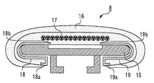
移動手摺8は、横(短手方向)断面が略C字状を呈しており、上記手摺駆動装置10による駆動と案内レール15による走行の案内とが、内側表面を介して行われる。即ち、移動手摺8には、その内面に、十分な駆動力を発生させるための高い摩擦特性(摩擦係数)と、走行時の走行抵抗(案内レール15との摺動抵抗)を低減させるための低い摩擦特性(摩擦係数)との双方の機能が要求される。
The moving
本実施の形態における移動手摺8は、本体樹脂部16、抗張体17、帆布18及び19により、その要部が構成される。
本体樹脂部16は、移動手摺8の要部を構成するものであり、横断面が略C字状を呈し、全体として無端状に形成されている。本体樹脂部16は、例えば、ゴムやポリウレタン等の樹脂部材によって構成される。なお、図2等では、本体樹脂部16が一種類の弾性体からなる場合を一例として示している。しかし、本体樹脂部16の構成はこのようなものに限られる訳ではなく、移動手摺8に付与する機能等に合わせて、本体樹脂部16を複数の樹脂層によって構成しても構わない。
The main part of the moving
The main
抗張体17は、移動手摺8に所定の引張強度を付与し、その伸びを防止するためのものである。抗張体17は、例えば、鋼製のワイヤを縒り合わせたものからなり、本体樹脂部16の内部に、その長手に沿って設けられている。なお、抗張体17は、スチールテープ等で構成しても良い。
The
帆布18及び19は、全体(或いは、少なくともその表面)が、フッ素樹脂繊維等の極めて低い摩擦特性を有する繊維によって織られたもの(織布)、或いは不織布からなる。帆布18及び19は、本体樹脂部16を構成する樹脂と同時に成形(一体成形)されることにより、本体樹脂部16の内面に強固に固定されている。
The
具体的に、一方の帆布18は、本体樹脂部16の一側部に設けられており、本体樹脂部16の一側部の内面に、その長手に沿って配置されている。帆布18の一側縁部18aは、例えば、コ字状(或いは、U字状)に湾曲されており、その端が本体樹脂部16の内部(樹脂内)にその長手に沿って埋め込まれている。
Specifically, one
他方の帆布19は、帆布18と対称の構成を有している。即ち、帆布19は、本体樹脂部16の他側部に設けられており、本体樹脂部16の他側部の内面に、その長手に沿って配置されている。帆布19の一側縁部19aは、例えば、コ字状(或いは、U字状)に湾曲されており、その端が本体樹脂部16の内部(樹脂内)にその長手に沿って埋め込まれている。
The
帆布18と帆布19との間には、本体樹脂部16の長手に沿って所定の間隔が形成されている。このため、帆布18の他側縁部18bと帆布19の他側縁部19bとの間には、本体樹脂部16の一部(本体樹脂部16を構成する樹脂)が露出する。手摺駆動装置10の駆動ローラ11は、帆布18及び19の各表面に接触することなく、且つ、本体樹脂部16の上記露出部分(露出内面)に接触して、移動手摺8を駆動する。
A predetermined interval is formed between the
移動手摺8の製造に際しては、先ず、図2に示す移動手摺8と同じ構成を有する長尺の手摺本体を製作した後、この手摺本体を所定の長さに切断してその両端部を接続することにより、無端状(環状)の移動手摺8を完成させる。
In manufacturing the
例えば、上記手摺本体を押し出し成形によって製造する場合、先ず、上記構成の抗張体17と帆布18及び19とを準備しておく。そして、帆布18が一側部の内面に、帆布19が他側部の内面に配置されるようにして、所定の樹脂との押し出し一体成形を行い、図4に示す断面の長尺の部材を形成する。その後、必要に応じて一回或いは複数回の成形を行い、図4に示す部材の外側表面を樹脂で覆って、図2に示す横断面C字状の本体樹脂部16(手摺本体)を完成させる。
For example, when manufacturing the handrail main body by extrusion molding, first, the
帆布18及び19は、所定繊維の織布或いは不織布によって構成されるため、成形時の張力や熱によってその寸法が多少変化する。このため、上記押し出しによる一体成形時、帆布18及び19は、それぞれの一側縁部18a及び19aを基準に位置決めが行われる。かかる構成であれば、手摺本体(移動手摺8)の形状を損なうことなく、帆布18及び19を本体樹脂部16の一側部内面及び他側部内面にその長手に渡って適切に配置することができる。
Since the
成形時の寸法変化により、帆布18及び19は、各他側縁部18b及び19bが手摺本体の反中央部側に移動する。しかし、帆布18及び19は一体化されていないため、成形時に折れ曲がるようなことなく、手摺本体の形状が損なわれることはない。なお、帆布18及び19については、予め収縮量等を見込んでその寸法設定を行うことも有効である。また、熱収縮が小さいフッ素樹脂繊維は、帆布18及び19を構成する繊維として特に有効な手段となり得る。
Due to the dimensional change at the time of molding, the
上記構成の移動手摺8(手摺本体)であれば、本体樹脂部16を構成する樹脂が、帆布18及び帆布19を構成する樹脂間に入り込み、帆布18と帆布19とを本体樹脂部16に強固に固定することができる。図2乃至図4に示すように、帆布18及び19間に配置された本体樹脂部16の内面を、帆布18及び19の各表面と面一に配置すれば、帆布18及び19の他側縁部18b及び19bを本体樹脂部16に更に強固に固定することができる。
In the case of the moving handrail 8 (handrail main body) having the above configuration, the resin constituting the main
図5はこの発明の実施の形態1におけるマンコンベアの移動手摺の他の構成を示す図4相当図である。図5に示すものでは、帆布18及び19の他側縁部18b及び19bも、一側縁部18a及び19aと同様に、その端を本体樹脂部16の内部(樹脂内)にその長手に沿って埋め込んでいる。かかる構成であれば、帆布18及び19がその他側縁部18b及び19b側から剥がれてしまうことを確実に防止できる。
FIG. 5 is a view corresponding to FIG. 4 showing another configuration of the moving handrail of the man conveyor according to the first embodiment of the present invention. In the case shown in FIG. 5, the other side edges 18 b and 19 b of the
実施の形態2.
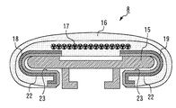
図6はこの発明の実施の形態2におけるマンコンベアの移動手摺を示す断面図である。図6は、本実施の形態における図1のA−A矢視に相当する。
FIG. 6 is a cross-sectional view showing a moving handrail of a man conveyor in
図6において、20は本体樹脂部16の一側部に設けられた棒状の補強材、21は本体樹脂部16の他側部に設けられた棒状の補強材である。補強材20及び21は、例えば、手摺本体を成形する時の温度で軟化・溶融されて、本体樹脂部16を構成する樹脂や帆布18及び19と一体化される材質(ナイロン、ポリエステル、ウレタン)で構成される。補強材20及び21は、ワイヤ等であっても構わない。
In FIG. 6, 20 is a rod-shaped reinforcing material provided on one side of the main
帆布18の一側縁部18aは、本体樹脂部16の長手に渡って補強材20(の一部)を囲むように、コ字状(或いは、U字状)に湾曲されている。帆布19の一側縁部19aも同様に、本体樹脂部16の長手に渡って補強材21(の一部)を囲むように、コ字状(或いは、U字状)に湾曲されている。
One
上述したように、帆布18及び19は、所定繊維の織布或いは不織布によって構成されるため、成形時の張力や熱によってその寸法が多少変化する。このため、本実施の形態では、押し出しによる一体成形時、帆布18については、その一側縁部18aを補強材20に押し付けて位置決めを行い、帆布19については、一側縁部19aを補強材21に押し付けて位置決めを行う。そして、かかる状態で、補強材20及び21とともに押し出しによる一体成形を行い、図4相当の断面を有する長尺の部材を形成する。かかる構成であれば、押し出しによる成形時に、帆布18及び19の各一側縁部18a及び19aの形状を常に安定させることができ、手摺本体(移動手摺8)の形状が損なわれることを確実に防止することができる。
As described above, since the
その他は、実施の形態1と同様の構成を有している。 The rest of the configuration is the same as that of the first embodiment.
実施の形態3.
図7はこの発明の実施の形態3におけるマンコンベアの移動手摺を示す断面図である。図7は本実施の形態における図1のA−A矢視に相当する。図8はこの発明の実施の形態3における帆布の構成を示す断面図である。
FIG. 7 is a cross-sectional view showing a moving handrail of a man conveyor in
本実施の形態では、帆布18及び19は、それぞれ、基布22と摺動布23との二層構造を有している。
基布22は、帆布18及び19の各下層部分を構成する。即ち、基布22は、本体樹脂部16の内面に設けられ、本体樹脂部16の長手に沿って配置されている。基布22は、例えば、剛性の増加や収縮性の低減といった種々の性能を帆布18及び19に付与するためのものである。基布22は、本体樹脂部16に直接固定されるため、本体樹脂部16を構成する樹脂との接着性に優れた繊維で構成しても良い。基布22は、例えば、ナイロン、ポリエステル、ウレタン等の繊維が用いられた織布からなる。
In the present embodiment, the
The
摺動布23は、帆布18及び19の各上層部分を構成する。摺動布23は、案内レール15との摺動抵抗を低減させるためのものである。このため、摺動布23は、基布22よりも低い摩擦特性を有しており、例えば、フッ素樹脂繊維等の極めて低い摩擦係数を有する繊維が用いられた織布から構成される。摺動布23は、基布22の表面を覆うように基布22に設けられており、帆布18及び19の各表面を形成する。摺動布23は、例えば、その繊維が、基布22の繊維に織り込まれることにより、基布22に強固に固定される。
The sliding
かかる構成であれば、帆布18及び19に、要求される種々の機能、例えば、本体樹脂部16を構成する樹脂との接着性や表面の低摩擦特性、全体の高剛性や低収縮性といった機能を、基布22と摺動布23とに分けて適切に付与することができる。
その他は、実施の形態1又は2と同様の構成を有している。
With such a configuration, various functions required for the
Others have the same configuration as in the first or second embodiment.
1 トラス
2 踏段
3 踏段チェーン
4 踏段駆動用スプロケット
5 駆動電動機
6 減速機
7 制御盤
8 移動手摺
9 欄干
10 手摺駆動装置
11 駆動ローラ
12 加圧ローラ
13 手摺駆動用スプロケット
14 手摺チェーン
15 案内レール
16 本体樹脂部
17 抗張体
18、19 帆布
18a、19a 一側縁部
18b、19b 他側縁部
20、21 補強材
22 基布
23 摺動布
DESCRIPTION OF SYMBOLS 1
Claims (10)
前記本体樹脂部に設けられ、前記本体樹脂部の一側部の内面に、前記本体樹脂部の長手に沿って配置された第1帆布と、
前記本体樹脂部に設けられ、前記本体樹脂部の他側部の内面に、前記第1帆布との間に所定の間隔を有して前記本体樹脂部の長手に沿って配置された第2帆布と、
を備え、
前記第1帆布及び前記第2帆布は、前記本体樹脂部を構成する樹脂と一体成形されたマンコンベアの移動手摺。 A main body resin portion having a C-shaped cross section and formed in an endless shape,
A first canvas provided in the main body resin portion, and disposed on an inner surface of one side portion of the main body resin portion along a length of the main body resin portion;
A second canvas provided in the main body resin portion and arranged along the length of the main body resin portion with a predetermined interval between the inner surface of the other side portion of the main body resin portion and the first canvas When,
With
The first canvas and the second canvas are moving handrails of a man conveyor formed integrally with a resin constituting the main body resin portion.
を備え、
前記第1帆布は、一側縁部が、前記本体樹脂部の長手に沿って一方の前記補強材を囲むように湾曲され、
前記第2帆布は、一側縁部が、前記本体樹脂部の長手に沿って他方の前記補強材を囲むように湾曲された
請求項1から請求項3の何れかに記載のマンコンベアの移動手摺。 A bar-shaped reinforcing material provided on one side and the other side of the main body resin portion, respectively, and disposed along the length of the main body resin portion;
With
The first canvas is curved so that one side edge portion surrounds one of the reinforcing members along the length of the main body resin portion,
The movement of the man conveyor according to any one of claims 1 to 3, wherein the second canvas is curved so that one side edge portion surrounds the other reinforcing member along a length of the main body resin portion. handrail.
前記本体樹脂部の内面に、その長手に沿って設けられた基布と、
前記基布の表面を覆うように前記基布に設けられ、前記基布よりも低い摩擦特性を有する摺動布と、
をそれぞれ備えた請求項1から請求項4の何れかに記載のマンコンベアの移動手摺。 The first canvas and the second canvas are:
A base cloth provided along the length of the inner surface of the main body resin portion;
A sliding cloth provided on the base cloth so as to cover the surface of the base cloth, and having a friction characteristic lower than that of the base cloth;
The moving handrail of the man conveyor according to any one of claims 1 to 4, comprising:
前記本体樹脂部に設けられ、前記本体樹脂部の一側部の内面に、前記本体樹脂部の長手に沿って配置された第1帆布と、
前記本体樹脂部に設けられ、前記本体樹脂部の他側部の内面に、前記第1帆布との間に所定の間隔を有して前記本体樹脂部の長手に沿って配置された第2帆布と、
を備え、
前記第1帆布及び前記第2帆布は、前記本体樹脂部を構成する樹脂と一体成形されたマンコンベア用手摺。 A long main body resin portion having a C-shaped cross section;
A first canvas provided in the main body resin portion, and disposed on an inner surface of one side portion of the main body resin portion along a length of the main body resin portion;
A second canvas provided in the main body resin portion and arranged along the length of the main body resin portion with a predetermined interval between the inner surface of the other side portion of the main body resin portion and the first canvas When,
With
The first canvas and the second canvas are handrails for a man conveyor which are integrally formed with a resin constituting the main body resin portion.
前記2つの帆布と所定の樹脂との押し出し一体成形を行い、一方の前記帆布が一側部の内面に、他方の前記帆布が他側部の内面に配置された横断面C字状を呈する手摺本体を成形するステップと、
を備えたマンコンベア用手摺の製造方法。 Preparing two long canvases,
A handrail having a C-shaped cross section in which the two canvases and a predetermined resin are integrally formed by extrusion and one canvas is disposed on the inner surface of one side and the other canvas is disposed on the inner surface of the other side. Molding the body;
Manufacturing method of handrail for man conveyor provided with
Priority Applications (1)
| Application Number | Priority Date | Filing Date | Title |
|---|---|---|---|
| JP2011095271A JP2012224458A (en) | 2011-04-21 | 2011-04-21 | Moving handrail for man conveyor, handrail for the man conveyor, and method for manufacturing the same |
Applications Claiming Priority (1)
| Application Number | Priority Date | Filing Date | Title |
|---|---|---|---|
| JP2011095271A JP2012224458A (en) | 2011-04-21 | 2011-04-21 | Moving handrail for man conveyor, handrail for the man conveyor, and method for manufacturing the same |
Publications (2)
| Publication Number | Publication Date |
|---|---|
| JP2012224458A true JP2012224458A (en) | 2012-11-15 |
| JP2012224458A5 JP2012224458A5 (en) | 2013-12-05 |
Family
ID=47275082
Family Applications (1)
| Application Number | Title | Priority Date | Filing Date |
|---|---|---|---|
| JP2011095271A Pending JP2012224458A (en) | 2011-04-21 | 2011-04-21 | Moving handrail for man conveyor, handrail for the man conveyor, and method for manufacturing the same |
Country Status (1)
| Country | Link |
|---|---|
| JP (1) | JP2012224458A (en) |
Cited By (3)
| Publication number | Priority date | Publication date | Assignee | Title |
|---|---|---|---|---|
| CN103991205A (en) * | 2013-02-18 | 2014-08-20 | 三菱电机大楼技术服务株式会社 | Making device of passenger conveyor mobile armrest |
| CN104003282A (en) * | 2013-02-25 | 2014-08-27 | 三菱电机大楼技术服务株式会社 | Passenger conveyor moving handrail and passenger conveyor handrail |
| CN105084190A (en) * | 2014-05-13 | 2015-11-25 | 三菱电机大楼技术服务株式会社 | Mobile handrail for passenger conveyor and manufacturing method for mobile handrail |
Citations (5)
| Publication number | Priority date | Publication date | Assignee | Title |
|---|---|---|---|---|
| JPS6082588A (en) * | 1983-10-11 | 1985-05-10 | 日立電線株式会社 | Manufacture of handrail |
| US4776446A (en) * | 1987-12-18 | 1988-10-11 | Westinghouse Electric Corp. | Handrail for transportation appartus |
| JP2008201496A (en) * | 2007-02-16 | 2008-09-04 | Tohoku Rubber Kk | Connecting structure of handrail and its manufacturing method |
| JP2010105801A (en) * | 2008-10-31 | 2010-05-13 | Mitsubishi Electric Building Techno Service Co Ltd | Movable handrail device of man conveyor, handrail for man conveyor, and manufacturing method thereof |
| JP2011042413A (en) * | 2009-08-19 | 2011-03-03 | Mitsubishi Electric Building Techno Service Co Ltd | Moving handrail of man conveyor and handrail for man conveyor |
-
2011
- 2011-04-21 JP JP2011095271A patent/JP2012224458A/en active Pending
Patent Citations (5)
| Publication number | Priority date | Publication date | Assignee | Title |
|---|---|---|---|---|
| JPS6082588A (en) * | 1983-10-11 | 1985-05-10 | 日立電線株式会社 | Manufacture of handrail |
| US4776446A (en) * | 1987-12-18 | 1988-10-11 | Westinghouse Electric Corp. | Handrail for transportation appartus |
| JP2008201496A (en) * | 2007-02-16 | 2008-09-04 | Tohoku Rubber Kk | Connecting structure of handrail and its manufacturing method |
| JP2010105801A (en) * | 2008-10-31 | 2010-05-13 | Mitsubishi Electric Building Techno Service Co Ltd | Movable handrail device of man conveyor, handrail for man conveyor, and manufacturing method thereof |
| JP2011042413A (en) * | 2009-08-19 | 2011-03-03 | Mitsubishi Electric Building Techno Service Co Ltd | Moving handrail of man conveyor and handrail for man conveyor |
Cited By (5)
| Publication number | Priority date | Publication date | Assignee | Title |
|---|---|---|---|---|
| CN103991205A (en) * | 2013-02-18 | 2014-08-20 | 三菱电机大楼技术服务株式会社 | Making device of passenger conveyor mobile armrest |
| CN103991205B (en) * | 2013-02-18 | 2017-04-12 | 三菱电机大楼技术服务株式会社 | Making device of passenger conveyor mobile armrest |
| CN104003282A (en) * | 2013-02-25 | 2014-08-27 | 三菱电机大楼技术服务株式会社 | Passenger conveyor moving handrail and passenger conveyor handrail |
| CN104003282B (en) * | 2013-02-25 | 2017-04-12 | 三菱电机大楼技术服务株式会社 | Passenger conveyor moving handrail and passenger conveyor handrail |
| CN105084190A (en) * | 2014-05-13 | 2015-11-25 | 三菱电机大楼技术服务株式会社 | Mobile handrail for passenger conveyor and manufacturing method for mobile handrail |
Similar Documents
| Publication | Publication Date | Title |
|---|---|---|
| JP5400765B2 (en) | Modular handrail structure for passenger conveyor handrails | |
| JP5098958B2 (en) | Man conveyor moving handrail device, man conveyor handrail and manufacturing method thereof | |
| EP3388381B1 (en) | Elevator belt with additive layer | |
| JP5682640B2 (en) | Manufacturing equipment for moving handrails for man conveyors | |
| JP5353552B2 (en) | Handrail for man conveyor and handrail for man conveyor | |
| AU2017268631B2 (en) | Overbraided non-metallic tension members | |
| JP5083316B2 (en) | Moving handrail for man conveyor | |
| JP5772744B2 (en) | Handrail for man conveyor and handrail for man conveyor | |
| JP5664160B2 (en) | Handrails for man conveyors, handrails for man conveyors, and canvas for moving handrails | |
| JP2012224458A (en) | Moving handrail for man conveyor, handrail for the man conveyor, and method for manufacturing the same | |
| KR102401760B1 (en) | Method for manufacturing moving handrail | |
| JP2010265086A (en) | Handrail for man conveyor | |
| EP2909372B1 (en) | Method of elevator cord cleaning and heating | |
| JP5446562B2 (en) | Processing method of moving handrail for man conveyor | |
| CN104003282B (en) | Passenger conveyor moving handrail and passenger conveyor handrail | |
| JP5493600B2 (en) | Handrail for man conveyor and handrail for man conveyor | |
| JP6015790B2 (en) | Canvas for handrails, handrails for man conveyors, handrails for man conveyors, and methods of manufacturing handrails for man conveyors | |
| JP2017001795A (en) | Passenger conveyor handrail belt and passenger conveyor | |
| JPH0859165A (en) | Handrail device of passenger conveyor | |
| JP2017014000A (en) | Moving handrail for passenger conveyor | |
| JP2015110453A (en) | Moving handrail of passenger conveyor | |
| JP2019112171A (en) | Passenger conveyor and passenger conveyor moving handrail | |
| JP2018150121A (en) | Handrail | |
| JP2002012383A (en) | Handrail of passenger conveyor | |
| JP2008001504A (en) | Movable handrail for passenger conveyor |
Legal Events
| Date | Code | Title | Description |
|---|---|---|---|
| A521 | Written amendment |
Free format text: JAPANESE INTERMEDIATE CODE: A523 Effective date: 20131022 |
|
| A621 | Written request for application examination |
Free format text: JAPANESE INTERMEDIATE CODE: A621 Effective date: 20131022 |
|
| A131 | Notification of reasons for refusal |
Free format text: JAPANESE INTERMEDIATE CODE: A131 Effective date: 20141104 |
|
| A521 | Written amendment |
Free format text: JAPANESE INTERMEDIATE CODE: A523 Effective date: 20141204 |
|
| A02 | Decision of refusal |
Free format text: JAPANESE INTERMEDIATE CODE: A02 Effective date: 20150602 |