JP2012206603A - Cabin light - Google Patents
Cabin light Download PDFInfo
- Publication number
- JP2012206603A JP2012206603A JP2011073635A JP2011073635A JP2012206603A JP 2012206603 A JP2012206603 A JP 2012206603A JP 2011073635 A JP2011073635 A JP 2011073635A JP 2011073635 A JP2011073635 A JP 2011073635A JP 2012206603 A JP2012206603 A JP 2012206603A
- Authority
- JP
- Japan
- Prior art keywords
- housing
- substrate
- light
- lens
- emitting diode
- Prior art date
- Legal status (The legal status is an assumption and is not a legal conclusion. Google has not performed a legal analysis and makes no representation as to the accuracy of the status listed.)
- Pending
Links
Images


Abstract
Description
本発明は、自動車の客室や荷室等の室内に備えられる車両用灯具である車内灯に関する。 The present invention relates to an interior lamp that is a vehicular lamp provided in a room such as a passenger compartment or a luggage compartment of an automobile.
従来、自動車の車内を照明するために、種々の車内灯が用いられている。車内灯においては、白熱電球や蛍光灯に加えて、近年は発光ダイオードが光源として用いられるようになっている。発光ダイオードを搭載した基板を灯具本体の内部に備えることで、電球や蛍光灯を用いた場合よりも消費電力を低減したり灯具を薄型に構成したりすることができる(例えば、特許文献1を参照)。 Conventionally, various interior lights are used to illuminate the interior of an automobile. In the interior lamps, in addition to incandescent bulbs and fluorescent lamps, light emitting diodes have recently been used as light sources. By providing a substrate mounted with a light emitting diode inside the lamp body, it is possible to reduce power consumption and to make the lamp thinner than when a light bulb or a fluorescent lamp is used (for example, see Patent Document 1). reference).
しかし、灯具を薄型にすると、灯具のハウジングが薄い箱状となるために強度が低下し、取り付け時に締結具を締めこむとハウジングが歪む虞があった。また、強度を高めるために立体的なリブ等の補強部を設けると、灯具が大型化したり、基板の収まりが悪くなったりする虞があった。 However, if the lamp is made thin, the housing of the lamp becomes a thin box shape, so that the strength is lowered. If the fastener is tightened during installation, the housing may be distorted. In addition, if a reinforcing portion such as a three-dimensional rib is provided in order to increase the strength, the lamp may be increased in size or the accommodation of the substrate may be deteriorated.
上記の実情を鑑み、本発明は、本体の大型化を防ぎつつ強度の低下を抑制した車内灯を提供することを目的とする。 In view of the above circumstances, an object of the present invention is to provide an interior lamp that suppresses a decrease in strength while preventing an increase in size of a main body.
本発明の車内灯は、「発光ダイオードを搭載した基板と、該基板が取り付けられる基板取付面を有するハウジングと、透光性を有する素材で形成されており、前記ハウジングに装着され、前記基板を覆うレンズと、を備える車内灯において、前記基板取付面には、前記基板の外形に対応した形状で突設された位置決めリブが設けられており、前記ハウジングを自動車の車内に固定するための締結具を受容する締結具受容孔が前記位置決めリブに穿設されている」ことを特徴とする。 The interior lamp of the present invention is formed of “a substrate on which a light-emitting diode is mounted, a housing having a substrate mounting surface to which the substrate is mounted, and a light-transmitting material. In the interior lamp comprising a covering lens, the board mounting surface is provided with positioning ribs protruding in a shape corresponding to the outer shape of the board, and fastening for fixing the housing in the car interior A fastener receiving hole for receiving a tool is formed in the positioning rib.
本発明の車内灯によれば、ハウジングの内側である基板取付面に、基板の位置決め構造であるとともにハウジングの強度を高める位置決めリブが突設されているので、本体の厚みを増すことなく強度を高めることができる。また、位置決めリブに締結具受容孔が穿設されているので、締結具を締める際に位置決めリブに力が加わるためにハウジングが変形しづらくなる。 According to the interior lamp of the present invention, since the positioning ribs that are the positioning structure of the board and increase the strength of the housing are projected on the board mounting surface inside the housing, the strength is increased without increasing the thickness of the main body. Can be increased. Further, since the fastener receiving hole is formed in the positioning rib, a force is applied to the positioning rib when the fastener is tightened, so that the housing is not easily deformed.
以上のように、本発明の車内灯によれば、灯具の内側に設けた基板の位置決め構造がハウジングの強度を高める構造を兼ねることで、本体の大型化を防ぎつつ強度の低下を抑制することができる。 As described above, according to the interior lamp of the present invention, the substrate positioning structure provided inside the lamp also serves as a structure that increases the strength of the housing, thereby preventing a decrease in strength while preventing an increase in the size of the main body. Can do.
以下、本発明の一実施形態である車内灯10について、図1〜図11に基き説明する。図1(a)は、車内灯をレンズ側から示す斜視図であり、図1(b)は、車内灯を車体取付面側から示す斜視図であり、図2は、車内灯の六面図であり、図3は、レンズを取り除いた状態を示す車内灯の正面図であり、図4は、図3におけるA−A’における断面図である。図5は、ハウジングを基板取付面側から示す斜視図であり、図6は、ハウジングを車体取付面側から示す斜視図であり、図7は、ハウジングの六面図である。図8(a)は、レンズの外面側を示す斜視図であり、図8(b)は、レンズの内面側を示す斜視図であり、図9は、レンズの六面図である。
Hereinafter, the
図1〜図4に示すように、車内灯10は、主としてハウジング20、レンズ30及び発光ダイオード基板40から構成される。ハウジング20はABS等の樹脂製であり、レンズ30はポリカーボネイト等の透光性を有する樹脂製である。車内灯10は、車体取付面22を自動車の室内の取付面(図示しない)に当接させて、締結具受容孔24に通されたネジ等の締結具(図示しない)によって室内の取付面に固定される。車内灯10の取り付け箇所は、客室天井、荷室天井、トランクの蓋内面、トランク内側面、ドア内側面など、必要に応じて車内の種々の箇所が適宜選択され得る。ここで、発光ダイオード基板40が、本発明の「基板」に相当する。
As shown in FIGS. 1 to 4, the
なお、車内灯10の向きについては、取付箇所に応じて取付向きが変わるため、あくまでも相対的なものであるが、以下の文中においては、車内灯10の上下左右は参照する図面の図示する方向に従うものとする。但し、六面図については、便宜上、光を放射するレンズ30の側を正面として記す。
In addition, about the direction of the
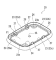
図5〜図7に示すように、ハウジング20は、額縁状の縁部26が底板部20aを囲むように設けられた皿状を呈している。底板部20aの基板取付面21には、縁部26の内側に位置決めリブ23が、発光ダイオード基板40(図3参照)の外周形状に沿った長方形枠状に突設されており、発光ダイオード基板40を内側に受容可能となっている。位置決めリブ23の延長上には、発光ダイオード基板40を係止するための爪部27が4箇所に設けられており、位置決めリブ23は、爪部27の設けられた所で、23a〜23dの4区間に分断されている。また、位置決めリブ23には、2箇所のボス部23eが対角線上に相当する位置に設けられており、ボス部23eには締結部受容孔24が各々穿設されている。基板取付面21の中央部には、配線を挿通可能な孔25が穿設されている。また、レンズ30を装着する際にレンズ30の係止爪31と係合してレンズ30を固定するための爪受容部28が、底板部20a及び縁部26の境界の隅に4箇所設けられている。底板部20ano基板取付面21の裏側には、平坦な車体取付面22が設けられている。
As shown in FIGS. 5-7, the
図8〜図9に示すように、レンズ30は、外面側は滑らかな曲面のドーム状を呈し、内面側に光を拡散させるためのレンズ形状が形成されている。すなわち、レンズ30の上部裏側には凸レンズ状に内面側に膨らんだ膨出部33が多数形成されており、レンズ30の側面から肩部にかけての内面側には、細かなピッチで山と谷が交互に形成された帯状カット部32が形成されている。レンズ30の下端には、ハウジング20の縁部26の内側に嵌め込むために外形が小さくなった挿入部34が設けられており、挿入部34には先述の係止爪31が、爪受容部28に各々対応する位置で4箇所設けられている。
As shown in FIGS. 8 to 9, the
図3〜図4に示すように、発光ダイオード基板40には、4個の発光ダイオード41と、車体側から供給される電力によって発光ダイオード41を点灯させるために必要な抵抗等の素子類が搭載されている。発光ダイオード基板40は、ハウジング20の位置決めリブ23によって位置決めされ、基板取付面21に当接し、4箇所の爪部27で係止されてハウジング20上に保持される。図示は省略するが、発光ダイオード基板40へ電力供給を行う配線は、孔25を通して車体取付面22側に引き出されて車体側の電源に接続される。
As shown in FIGS. 3 to 4, the light
以上のように、本発明の実施形態である車内灯1によれば、基板取付面21に位置決めリブ23が突設されており、発光ダイオード基板40の位置決め構造をなすとともにハウジングの強度を高める。基板取付面21は車内灯1の内部側であり、位置決めリブ23もまた内部側に設けられており外部に突出することがないため、車内灯1の厚みを増すことなく強度を高めることができる。また、位置決めリブ23のボス部23eに締結具受容孔21が穿設されているので、車体に取り付けるために締結具を締める際にも、ボス部23eに力が加わるため、ハウジング20が変形しづらくなる。
As described above, according to the interior lamp 1 according to the embodiment of the present invention, the positioning ribs 23 project from the
また、車内灯1は、縁部26と位置決めリブ23とが別個に設けられているため、組み付けやメンテナンスの際に特定箇所に応力が集中する虞を低減させることができる。すなわち、レンズ30の着脱時には縁部26が外側にたわみ、発光ダイオード基板40の着脱時には位置決めリブ23が外側にたわむ。縁部26と位置決めリブ23とが接合され一体的に形成されていた場合と比較すると、応力集中によって係止のための爪部等が破損する虞が低減される。
Moreover, since the
なお、本発明の実施形態は上記の構成に限定されるものではなく、以下に示すように種々に変更することができる。 In addition, embodiment of this invention is not limited to said structure, As shown below, it can change variously.
すなわち、上記の実施形態では、レンズ30がドーム状を呈するものを示したが、これに限定されるものではなく、レンズ30は平板状であってもよいし、より複雑な形状を呈するものであってもよい。これにより、種々の取り付け箇所や用途に対応した灯具において、本発明を適用することができる。
That is, in the above embodiment, the
また、上記の実施形態では、ボス部23e及び締結具受容孔24が2箇所設けられているものを示したが、3箇所以上に設けられていてもよい。ボス部23e及び締結具受容孔24が多く設けられているほど、ハウジング20の剛性が高まるため強度を向上させることができる。
Moreover, in said embodiment, although the boss |
10…車内灯、20…ハウジング、21…基板取付面、23…位置決めリブ、24…締結具受容孔、30…レンズ、40…発光ダイオード基板(基板)
DESCRIPTION OF
Claims (1)
該基板が取り付けられる基板取付面を有するハウジングと、
透光性を有する素材で形成されており、前記ハウジングに装着され、前記基板を覆うレンズと、
を備える車内灯において、
前記基板取付面には、前記基板の外形に対応した形状で突設された位置決めリブが設けられており、
前記ハウジングを自動車の車内に固定するための締結具を受容する締結具受容孔が前記位置決めリブに穿設されている
ことを特徴とする車内灯。 A substrate mounted with a light emitting diode;
A housing having a substrate mounting surface to which the substrate is mounted;
A lens that is formed of a light-transmitting material, is mounted on the housing, and covers the substrate;
Interior lights with
The board mounting surface is provided with positioning ribs protruding in a shape corresponding to the outer shape of the board,
A vehicle interior light characterized in that a fastener receiving hole for receiving a fastener for fixing the housing in a vehicle is formed in the positioning rib.
Priority Applications (1)
| Application Number | Priority Date | Filing Date | Title |
|---|---|---|---|
| JP2011073635A JP2012206603A (en) | 2011-03-29 | 2011-03-29 | Cabin light |
Applications Claiming Priority (1)
| Application Number | Priority Date | Filing Date | Title |
|---|---|---|---|
| JP2011073635A JP2012206603A (en) | 2011-03-29 | 2011-03-29 | Cabin light |
Publications (1)
| Publication Number | Publication Date |
|---|---|
| JP2012206603A true JP2012206603A (en) | 2012-10-25 |
Family
ID=47186745
Family Applications (1)
| Application Number | Title | Priority Date | Filing Date |
|---|---|---|---|
| JP2011073635A Pending JP2012206603A (en) | 2011-03-29 | 2011-03-29 | Cabin light |
Country Status (1)
| Country | Link |
|---|---|
| JP (1) | JP2012206603A (en) |
Cited By (3)
| Publication number | Priority date | Publication date | Assignee | Title |
|---|---|---|---|---|
| US9512981B2 (en) | 2013-06-17 | 2016-12-06 | Toshiba Lighting & Technology Corporation | Luminaire for interior lamp provided in automobile |
| JP2019034687A (en) * | 2017-08-21 | 2019-03-07 | 株式会社ミツバ | Lighting device |
| JP2021024427A (en) * | 2019-08-05 | 2021-02-22 | 豊田合成株式会社 | Indoor illumination device |
-
2011
- 2011-03-29 JP JP2011073635A patent/JP2012206603A/en active Pending
Cited By (3)
| Publication number | Priority date | Publication date | Assignee | Title |
|---|---|---|---|---|
| US9512981B2 (en) | 2013-06-17 | 2016-12-06 | Toshiba Lighting & Technology Corporation | Luminaire for interior lamp provided in automobile |
| JP2019034687A (en) * | 2017-08-21 | 2019-03-07 | 株式会社ミツバ | Lighting device |
| JP2021024427A (en) * | 2019-08-05 | 2021-02-22 | 豊田合成株式会社 | Indoor illumination device |
Similar Documents
| Publication | Publication Date | Title |
|---|---|---|
| US9016918B2 (en) | Lighting device | |
| KR101413691B1 (en) | Fitting part for a vehicle interior, comprising a lighting surface | |
| US20170210275A1 (en) | Passenger compartment illumination device | |
| KR20130024747A (en) | Door mirror for vehicle | |
| CN102959319A (en) | Light source turn-on device for headlamp | |
| WO2015076114A1 (en) | Vehicle lamp | |
| JP4700081B2 (en) | Vehicle lighting device | |
| JP2012206603A (en) | Cabin light | |
| JP2008195284A (en) | Vehicular lighting fixture | |
| CN210179516U (en) | Vehicle lamp | |
| JP6149559B2 (en) | LED lights | |
| JP6833441B2 (en) | Vehicle lighting | |
| JP2005216831A (en) | Vehicular outside mirror device | |
| JP5546010B2 (en) | emblem | |
| JP7079072B2 (en) | Display sign light | |
| JP6931553B2 (en) | Vehicle lighting | |
| KR200466434Y1 (en) | Case for filling type lighting | |
| WO2021060291A1 (en) | Vehicular lighting device | |
| JP6053600B2 (en) | Light emitting device for vehicle | |
| CN209977850U (en) | Reading lamp and car in car | |
| JP2020093603A (en) | Vehicle lamp fitting | |
| KR100188152B1 (en) | Aux stop lamp | |
| JP3197718U (en) | Lighting device for vehicle | |
| JP6164493B2 (en) | Car interior lighting system | |
| JP5668598B2 (en) | Vehicle lighting |