JP2012206069A - Device for dissolving and supplying chemical agent - Google Patents
Device for dissolving and supplying chemical agent Download PDFInfo
- Publication number
- JP2012206069A JP2012206069A JP2011075502A JP2011075502A JP2012206069A JP 2012206069 A JP2012206069 A JP 2012206069A JP 2011075502 A JP2011075502 A JP 2011075502A JP 2011075502 A JP2011075502 A JP 2011075502A JP 2012206069 A JP2012206069 A JP 2012206069A
- Authority
- JP
- Japan
- Prior art keywords
- water
- tank
- drug
- chemical
- dissolving
- Prior art date
- Legal status (The legal status is an assumption and is not a legal conclusion. Google has not performed a legal analysis and makes no representation as to the accuracy of the status listed.)
- Withdrawn
Links
- 239000013043 chemical agent Substances 0.000 title abstract 3
- XLYOFNOQVPJJNP-UHFFFAOYSA-N water Substances O XLYOFNOQVPJJNP-UHFFFAOYSA-N 0.000 claims abstract description 42
- 239000007787 solid Substances 0.000 claims abstract description 13
- 239000007864 aqueous solution Substances 0.000 claims abstract description 9
- 239000003814 drug Substances 0.000 claims description 43
- 229940079593 drug Drugs 0.000 claims description 32
- 238000004090 dissolution Methods 0.000 claims description 25
- 239000000126 substance Substances 0.000 abstract description 27
- 230000007797 corrosion Effects 0.000 abstract description 2
- 238000005260 corrosion Methods 0.000 abstract description 2
- 239000000243 solution Substances 0.000 abstract description 2
- 239000003795 chemical substances by application Substances 0.000 description 15
- 238000001816 cooling Methods 0.000 description 11
- 229940126589 solid medicine Drugs 0.000 description 10
- 238000002347 injection Methods 0.000 description 6
- 239000007924 injection Substances 0.000 description 6
- 239000000460 chlorine Substances 0.000 description 5
- 229910052801 chlorine Inorganic materials 0.000 description 5
- ZAMOUSCENKQFHK-UHFFFAOYSA-N Chlorine atom Chemical compound [Cl] ZAMOUSCENKQFHK-UHFFFAOYSA-N 0.000 description 4
- 239000000498 cooling water Substances 0.000 description 4
- 239000004480 active ingredient Substances 0.000 description 3
- 238000005192 partition Methods 0.000 description 3
- 239000000945 filler Substances 0.000 description 2
- YRIZYWQGELRKNT-UHFFFAOYSA-N 1,3,5-trichloro-1,3,5-triazinane-2,4,6-trione Chemical compound ClN1C(=O)N(Cl)C(=O)N(Cl)C1=O YRIZYWQGELRKNT-UHFFFAOYSA-N 0.000 description 1
- ZKQDCIXGCQPQNV-UHFFFAOYSA-N Calcium hypochlorite Chemical compound [Ca+2].Cl[O-].Cl[O-] ZKQDCIXGCQPQNV-UHFFFAOYSA-N 0.000 description 1
- KZBUYRJDOAKODT-UHFFFAOYSA-N Chlorine Chemical compound ClCl KZBUYRJDOAKODT-UHFFFAOYSA-N 0.000 description 1
- 241000195493 Cryptophyta Species 0.000 description 1
- 241000233866 Fungi Species 0.000 description 1
- 229920001131 Pulp (paper) Polymers 0.000 description 1
- 239000008186 active pharmaceutical agent Substances 0.000 description 1
- 150000001804 chlorine Chemical class 0.000 description 1
- -1 chloro-isocyanuric acid compound Chemical class 0.000 description 1
- CEJLBZWIKQJOAT-UHFFFAOYSA-N dichloroisocyanuric acid Chemical compound ClN1C(=O)NC(=O)N(Cl)C1=O CEJLBZWIKQJOAT-UHFFFAOYSA-N 0.000 description 1
- 239000000428 dust Substances 0.000 description 1
- 239000007788 liquid Substances 0.000 description 1
- 238000000034 method Methods 0.000 description 1
- 239000007921 spray Substances 0.000 description 1
- 229950009390 symclosene Drugs 0.000 description 1
Images


Abstract
Description
本発明は、固形薬剤を水に溶解させて薬剤の水溶液を供給するための薬剤溶解供給装置に係り、特に塩素系薬剤の溶解及び供給に好適な薬剤溶解供給装置に関する。 The present invention relates to a drug dissolution supply apparatus for supplying a drug aqueous solution by dissolving a solid drug in water, and more particularly to a drug dissolution supply apparatus suitable for dissolution and supply of a chlorine-based drug.
冷却水系、紙パルププロセス水系、集塵水系、スクラバー水系、プールなどの水系に塩素系薬剤を添加して菌類や藻類による障害を防止することが広く行われている(例えば特許文献1)。 It has been widely practiced to add a chlorine-based chemical to a water system such as a cooling water system, a paper pulp process water system, a dust collection water system, a scrubber water system, and a pool to prevent damage caused by fungi and algae (for example, Patent Document 1).
従来、固形薬剤を水に溶解させて薬剤水溶液として供給するための薬剤溶解供給装置として、図2に概略的に示す上向流方式のものが用いられている。図2において、固形薬剤Aを収容した槽1の底部の流入口1aにポンプ2から流量計5を介して水を供給し、この水を固形薬剤Aと接触させる。固形薬剤が溶け込んだ水溶液は、槽1上部の流出口1bから流出し、水系に添加される。槽1の上部には、薬剤補充口1cが設けられ、蓋1dが水密的に装着されている。
2. Description of the Related Art Conventionally, an upward flow type apparatus schematically shown in FIG. 2 is used as a drug dissolution supply apparatus for dissolving a solid drug in water and supplying it as a drug aqueous solution. In FIG. 2, water is supplied from the
上記従来の薬剤溶解供給装置では、蓋1dが補充口1cに水密的に装着されており、開閉しにくい。
In the conventional drug dissolution and supply apparatus, the
また、上記従来の薬剤溶解供給装置において、固形薬剤Aが塩素系薬剤である場合、槽1内に水を供給して、固形薬剤Aが水に濡れた場合、通水停止後、固形薬剤Aの表面から塩素系薬剤と残留水分との反応により塩素系ガスが発生し、この塩素系ガスが流量計5と接触して流量計5を腐食させるおそれがある。
Moreover, in the said conventional chemical | medical agent melt | dissolution supply apparatus, when the solid chemical | medical agent A is a chlorinated chemical | medical agent, when water is supplied in the tank 1 and the solid chemical | medical agent A gets wet with water, after passing water stop, solid chemical | medical agent A There is a possibility that chlorine gas is generated from the surface of the liquid due to the reaction between the chlorine-based chemical and residual moisture, and this chlorine-based gas comes into contact with the
本発明は、上記従来の問題点を解決し、薬剤補充口の開閉が容易な薬剤溶解供給装置を提供することを目的とする。 An object of the present invention is to solve the above-mentioned conventional problems and to provide a drug dissolution supply device in which a drug replenishing port can be easily opened and closed.
また、本発明は、その一態様において、流量計等の機器の腐食が防止される薬剤溶解供給装置を提供することを目的とする。 Moreover, this invention aims at providing the chemical | medical agent melt | dissolution supply apparatus in which the corrosion of apparatuses, such as a flowmeter, is prevented in the one aspect | mode.
本発明(請求項1)の薬剤溶解供給装置は、固形薬剤を収容する槽と、該槽内に水を供給するポンプとを有する薬剤溶解供給装置において、該槽の上部に蓋付きの薬剤補充口が設けられており、該槽の上部に該水の散水器が設けられ、該槽の下部に薬剤水溶液の流出口が設けられていることを特徴とするものである。 The drug dissolution supply apparatus according to the present invention (Claim 1) is a drug dissolution supply apparatus having a tank for storing a solid drug and a pump for supplying water into the tank, and replenishing the drug with a lid on the upper part of the tank. A mouth is provided, the water sprinkler is provided in the upper part of the tank, and the outlet of the aqueous chemical solution is provided in the lower part of the tank.
請求項2の薬剤溶解供給装置は、請求項1において、前記散水器に連なる給水管に上向流部を設け、該上向流部に流量計及び逆止弁を、該流量計が逆止弁の上位となるように設けたことを特徴とするものである。 According to a second aspect of the present invention, there is provided the chemical dissolution and supply apparatus according to the first aspect, wherein an upward flow portion is provided in a water supply pipe connected to the water sprinkler, and a flow meter and a check valve are provided in the upward flow portion. It is provided so that it may become the upper rank of a valve.
請求項3の薬剤溶解供給装置は、請求項1又は2において、固形薬剤が塩素系薬剤であることを特徴とするものである。 A drug dissolution supply apparatus according to a third aspect is characterized in that, in the first or second aspect, the solid drug is a chlorinated drug.
本発明の薬剤溶解供給装置では、固形薬剤を溶解するための水を槽の上部から散水して固形薬剤と接触させるようにしており、槽内が満水とならない。そのため、補充口の蓋を水密的にする必要がなく、補充口の蓋の開閉が容易となる。 In the medicine dissolution and supply apparatus of the present invention, water for dissolving the solid medicine is sprayed from the upper part of the tank so as to come into contact with the solid medicine, and the inside of the tank does not become full. Therefore, it is not necessary to make the cover of the replenishing port watertight, and it is easy to open and close the cover of the replenishing port.
また、本発明の一態様においては、散水器への給水系統の途中に上向流部を設け、この上向流部に流量計と逆止弁を流量計が上位となるように設置している。この場合、ポンプを停止すると、上向流部の逆止弁よりも上側に水が残り、流量計が水封状態となる。このため、固形薬剤が塩素系薬剤の場合、槽内で発生した塩素系ガスが流量計に接触することが防止され、流量計の耐久性が向上する。 Moreover, in one aspect of the present invention, an upward flow part is provided in the middle of the water supply system to the sprinkler, and a flow meter and a check valve are installed in the upward flow part so that the flow meter is at the upper level. Yes. In this case, when the pump is stopped, water remains above the check valve in the upward flow portion, and the flow meter is in a water-sealed state. For this reason, when a solid chemical | medical agent is a chlorinated chemical | medical agent, it is prevented that the chlorinated gas generated in the tank contacts a flowmeter, and durability of a flowmeter improves.
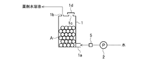
以下、図1を参照して実施の形態について説明する。 Hereinafter, an embodiment will be described with reference to FIG.
槽3は、上部にシャワーヘッド状の散水器3aが設置され、下部の一方の側面部に流出口3bが設けられている。この流出口3bには、固形薬剤Aの流出防止用のメッシュ4が設けられている。散水器3aには、ポンプ2からの水が逆止弁6及び流量計5を有する給水管7を介して導入可能とされている。
The tank 3 is provided with a shower head-
槽3の上部には固形薬剤Aの補充口3cが設けられ、蓋3dが着脱自在に装着されている。なお、給水管7の途中は上下方向に延在した上向流部7aとなっており、流量計5及び逆止弁7は、この上向流部7aに、流量計5が逆止弁6の上側となるように設置されている。
In the upper part of the tank 3, a replenishing
このように構成された薬剤溶解供給装置において、薬剤水溶液を供給するときには、ポンプ2を作動させ、水を散水器3aから散水する。散水された水は槽3内の固形薬剤Aと接触し、薬剤成分が溶け込んだ水溶液となって流出口3bから流出する。
In the drug dissolution and supply apparatus configured as described above, when supplying the drug aqueous solution, the
このように、この薬剤溶解供給装置では、固形薬剤を溶解するための水を槽3内に上方から散水するので、槽3内が満水となることはない。従って、補充口3cの蓋3dは厳重な水密性を必要とせず、蓋3dの開閉が容易である。
Thus, in this chemical | medical agent melt | dissolution supply apparatus, since the water for melt | dissolving a solid chemical | medical agent is sprinkled from the upper direction in the tank 3, the inside of the tank 3 does not become full. Therefore, the
また、この実施の形態では、給水管7に上向流部7aを設け、流量計5を逆止弁6よりも上位に設置している。そのため、ポンプ2を停止したときには、上向流部7aの逆止弁6よりも上側に水が残り、流量計5が水封状態となっている。このため固形薬剤Aが塩素系薬剤であり、通水停止時に該塩素系薬剤から塩素系ガスが発生しても、このガスが流量計5に到達しない。このため、流量計5が腐食することが防止され、流量計5の耐久性が向上する。
In this embodiment, the
固形薬剤Aとしては、トリクロロイソシアヌル酸、ジクロロイソシアヌル酸ナトリウムなどのクロルイソシアヌル酸化合物、次亜塩素酸カルシウムなどの塩素系薬剤が好適であるが、これに限定されない。 The solid drug A is preferably a chloro-isocyanuric acid compound such as trichloroisocyanuric acid or sodium dichloroisocyanurate, or a chlorine-based drug such as calcium hypochlorite, but is not limited thereto.
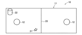
ところで、本発明のような薬剤溶解供給装置を開放式循環冷却水系の冷却塔に設置する場合の好適な位置又は薬注位置について図3,4を参照して説明する。 By the way, the suitable position or chemical injection position in the case of installing the chemical | medical agent melt | dissolution supply apparatus like this invention in the cooling tower of an open type circulating cooling water system is demonstrated with reference to FIG.
図3の通り、冷却塔10内の水がピット11の吸い込み部12から配管13、ポンプ14、配管15、熱交換器(図示略)及び配管16を通って冷却塔10に戻り、散水管17から冷却塔10内の充填材18に注ぎかけられる。冷却水は充填材18に沿って伝わり落ち、この間に水の一部が蒸発し、冷却水が冷却される。補給水は配管19からピット11内に供給される。冷却塔10が大形の場合、ピット11内に仕切り板20が設けられる。なお、仕切り板20を挟んで隣接する室(セル)は、仕切り板20に設けられた連結部20aによって連通している。
As shown in FIG. 3, the water in the
このような冷却塔10にスライムコントロール剤を薬注する場合、図4の通り、薬注装置22と、スライムコントロール剤の有効成分濃度を測定するためのセンサ21とを吸い込み部12を挟んで対称となるように配置するのが好ましい。室(セル)が複数ある場合には、薬注装置22とセンサ21とを同一セルに配置する。
When the slime control agent is poured into such a
この冷却塔10においては、溶解した薬剤が循環水と混合された後、センサ21と接触するようになるので平均的な濃度が測定できるようになる。
In the
また、セルが複数ある系において、設備の稼動有無がインターロック信号として取れないような場合に設備が休止中に薬剤水溶液がピット内に添加されても早く感知できるために薬剤を過剰供給することが防止される。 Also, in a system with multiple cells, when the equipment operation is not available as an interlock signal, even if the aqueous solution is added to the pit while the equipment is out of service, it can be quickly detected so that the drug can be supplied in excess. Is prevented.
薬注装置を冷却塔外に配置し、薬剤水溶液をピットに添加する場合には、この添加位置が上記薬注装置22の位置となるようにすればよい。
When the chemical injection device is disposed outside the cooling tower and the chemical aqueous solution is added to the pit, the addition position may be the position of the
なお、仮に薬注装置22とセンサ21とが近接配置されていると、次のような不具合がある。
If the
即ち、溶解槽と濃度センサの位置が近い場合、高濃度の薬剤が濃度センサに接して、系内の有効成分を高く見積もってしまう場合や、センサ自体が高濃度の薬剤により劣化してしまうことがあった。 In other words, when the dissolution tank and the concentration sensor are close to each other, a high concentration medicine comes into contact with the concentration sensor and the active ingredient in the system is estimated to be high, or the sensor itself is deteriorated by the high concentration medicine. was there.
一方で、溶解槽と濃度センサの位置が遠い場合、濃度を低く感知してしまうため、実際の有効成分濃度が高くなりすぎることがあった。 On the other hand, when the positions of the dissolution tank and the concentration sensor are far from each other, the concentration is sensed low, and the actual active ingredient concentration sometimes becomes too high.
また、設備の稼動有無がインターロック信号として取れない系である場合に設備が休止中であるにも関わらず、時間の経過による薬品有効成分低下に伴い、薬剤が供給されることがある。その場合、冷却塔のセルが複数あって溶解槽と濃度センサが異なるセル(遠い位置)にある場合に過剰に供給させることがあった。 Further, when the system is incapable of taking an operation signal as an interlock signal, the medicine may be supplied along with a decrease in active pharmaceutical ingredients over time, even though the equipment is at rest. In that case, when there are a plurality of cells of the cooling tower and the dissolution tank and the concentration sensor are in different cells (distant positions), excessive supply may occur.
これに対し、上記図4のような位置関係とすることにより、溶解槽から供給される薬剤が冷却塔を循環する際に十分に混合され、平均的な濃度を示すようになった。また、水が循環していない場合(設備休止中の時)に万が一、薬剤が供給されても位置関係として遠くはないため、過剰に供給される前に感知される。 On the other hand, by setting the positional relationship as shown in FIG. 4 above, the chemical supplied from the dissolution tank is sufficiently mixed when circulating through the cooling tower, and shows an average concentration. Also, when water is not circulating (when the equipment is not in operation), even if the medicine is supplied, it is not far from the positional relationship, so it is detected before being supplied excessively.
1,3 槽
2 ポンプ
3a 散水器
3b 流出口
3c 補充口
3d 蓋
4 メッシュ
5 流量計
6 逆止弁
A 固形薬剤
1,3
Claims (3)
該槽の上部に蓋付きの薬剤補充口が設けられており、
該槽の上部に該水の散水器が設けられ、該槽の下部に薬剤水溶液の流出口が設けられていることを特徴とする薬剤溶解供給装置。 In a drug dissolution and supply apparatus having a tank for storing a solid drug and a pump for supplying water into the tank,
A medicine replenishing port with a lid is provided at the top of the tank,
An apparatus for dissolving and supplying a drug, wherein the water sprinkler is provided in an upper part of the tank, and an outlet of the aqueous solution of the drug is provided in a lower part of the tank.
Priority Applications (1)
| Application Number | Priority Date | Filing Date | Title |
|---|---|---|---|
| JP2011075502A JP2012206069A (en) | 2011-03-30 | 2011-03-30 | Device for dissolving and supplying chemical agent |
Applications Claiming Priority (1)
| Application Number | Priority Date | Filing Date | Title |
|---|---|---|---|
| JP2011075502A JP2012206069A (en) | 2011-03-30 | 2011-03-30 | Device for dissolving and supplying chemical agent |
Publications (1)
| Publication Number | Publication Date |
|---|---|
| JP2012206069A true JP2012206069A (en) | 2012-10-25 |
Family
ID=47186337
Family Applications (1)
| Application Number | Title | Priority Date | Filing Date |
|---|---|---|---|
| JP2011075502A Withdrawn JP2012206069A (en) | 2011-03-30 | 2011-03-30 | Device for dissolving and supplying chemical agent |
Country Status (1)
| Country | Link |
|---|---|
| JP (1) | JP2012206069A (en) |
Cited By (2)
| Publication number | Priority date | Publication date | Assignee | Title |
|---|---|---|---|---|
| CN103148838A (en) * | 2013-02-06 | 2013-06-12 | 清华大学 | Groundwater aeration repair process simulation test system and method |
| CN106745561A (en) * | 2015-11-25 | 2017-05-31 | 深圳市科瑞德消毒用品科技开发有限公司 | A kind of automatic chemical dosing bucket |
-
2011
- 2011-03-30 JP JP2011075502A patent/JP2012206069A/en not_active Withdrawn
Cited By (2)
| Publication number | Priority date | Publication date | Assignee | Title |
|---|---|---|---|---|
| CN103148838A (en) * | 2013-02-06 | 2013-06-12 | 清华大学 | Groundwater aeration repair process simulation test system and method |
| CN106745561A (en) * | 2015-11-25 | 2017-05-31 | 深圳市科瑞德消毒用品科技开发有限公司 | A kind of automatic chemical dosing bucket |
Similar Documents
| Publication | Publication Date | Title |
|---|---|---|
| US6627073B2 (en) | Water treatment device | |
| JP4130588B2 (en) | Duplex solid chemical supply system | |
| CN107201631B (en) | Automatic washing machine putting device with water quality treatment function and roller washing machine | |
| US20110180395A1 (en) | Advanced Chlorine Generating System | |
| CA2593660A1 (en) | Chemical solution distributing apparatus and chemicals | |
| CN107445261B (en) | A kind of sodium hypochlorite dosing system | |
| JP5295753B2 (en) | Ozone water generator | |
| JP2012206069A (en) | Device for dissolving and supplying chemical agent | |
| JP2011177321A (en) | Finger sterilizing apparatus | |
| JP7180008B2 (en) | Chlorinated water generator | |
| CN108137356A (en) | Ballast water treatment plant and ballast water processing | |
| JP6291974B2 (en) | Sanitized water generator | |
| KR101941375B1 (en) | Generation-system for antiseptic solution including chlorine | |
| JP3147150U (en) | cooling tower | |
| JP5870501B2 (en) | Drug dissolution supply device | |
| JP5877031B2 (en) | Hypochlorous acid water production equipment | |
| JP5208907B2 (en) | Artificial hot spring equipment | |
| JP6331006B2 (en) | Sanitized water generator | |
| JPS6143116B2 (en) | ||
| KR100841554B1 (en) | Apparatus for shower | |
| JP3256693B2 (en) | Apparatus for producing high-concentration saline and apparatus for producing sterilized water containing hypochlorous acid using the same | |
| JP6660017B2 (en) | Regeneration liquid supply unit | |
| JP2015119883A (en) | Air purifying machine | |
| JP6292393B2 (en) | Sanitized water generator | |
| JP2017018897A (en) | Electrolytic water generator and washing machine |
Legal Events
| Date | Code | Title | Description |
|---|---|---|---|
| A300 | Application deemed to be withdrawn because no request for examination was validly filed |
Free format text: JAPANESE INTERMEDIATE CODE: A300 Effective date: 20140603 |