JP2012205497A - Power storage device that can generate power with vibrations - Google Patents
Power storage device that can generate power with vibrations Download PDFInfo
- Publication number
- JP2012205497A JP2012205497A JP2012063491A JP2012063491A JP2012205497A JP 2012205497 A JP2012205497 A JP 2012205497A JP 2012063491 A JP2012063491 A JP 2012063491A JP 2012063491 A JP2012063491 A JP 2012063491A JP 2012205497 A JP2012205497 A JP 2012205497A
- Authority
- JP
- Japan
- Prior art keywords
- annular
- power generation
- motion block
- magnet
- storage device
- Prior art date
- Legal status (The legal status is an assumption and is not a legal conclusion. Google has not performed a legal analysis and makes no representation as to the accuracy of the status listed.)
- Granted
Links
Images


Classifications
-
- H—ELECTRICITY
- H02—GENERATION; CONVERSION OR DISTRIBUTION OF ELECTRIC POWER
- H02K—DYNAMO-ELECTRIC MACHINES
- H02K35/00—Generators with reciprocating, oscillating or vibrating coil system, magnet, armature or other part of the magnetic circuit
- H02K35/02—Generators with reciprocating, oscillating or vibrating coil system, magnet, armature or other part of the magnetic circuit with moving magnets and stationary coil systems
Abstract
Description
本革新的発明は軸方向に往復振動して発電可能な蓄電装置の一種であって、柱形磁石が環状の発電コイルを通過する外側に外側導磁体を設置することにより、柱形磁石の磁極間が環状の発電コイルを通過する磁気抵抗を減らし、柱形磁石と外側導磁体を一緒にモーションブロックアセンブリ(106)に結合し、かつ同期に軸方向に移動することにより、環状の発電コイルを通過し、更にレンツの法則の効果により、環状の発電コイルにより電気エネルギーを作り、及び整流充電回路を経て、電気エネルギーを蓄電装置に貯蔵し、また電気エネルギーの入出力インタフェースとする蓄電装置の正極の入出力端及び負極の入出力端を設置する。 This innovative invention is a kind of power storage device that can generate power by reciprocating vibration in the axial direction, and the magnetic pole of the columnar magnet is provided by installing an outer magnetic conductor outside the columnar magnet that passes through the annular power generation coil. The annular generator coil is reduced by reducing the magnetic resistance passing through the annular generator coil, coupling the columnar magnet and the outer conductor together to the motion block assembly (106), and moving axially synchronously. The positive electrode of the power storage device that passes through and further generates electrical energy by the annular power generation coil, stores the electrical energy in the power storage device through the rectification and charging circuit, and also serves as an input / output interface for electrical energy. The input / output terminal and negative input / output terminal are installed.
従来の軸方向に往復振動する振動発電装置は、円柱形磁石が軸方向に環状の発電コイルとカップリングすることを通して、軸方向に振動変位させることにより、発電用コイルがレンツの法則の効果を通して、電気エネルギーを作る。 A conventional vibration power generator that reciprocally vibrates in an axial direction has a cylindrical magnet coupled with an annular power generation coil in the axial direction, and vibrates and displaces in the axial direction, whereby the power generation coil passes through the effect of Lenz's law. Make electrical energy.
しかし、その円柱形磁石と環状の発電コイルの結合磁力線は、空気によって伝導すると、磁気抵抗が大きいために、相対的に発電電気エネルギーの電圧が低くなり、貯蔵し難いことはその欠点である。 However, when the coupling magnetic field lines of the cylindrical magnet and the annular power generation coil are conducted by air, the magnetic resistance is large, so that the voltage of the generated electric energy is relatively low and is difficult to store.
本発明は円柱形かつ軸方向に異なる極性である磁極の柱形磁石を備え、及びその外部の外側導磁体に覆われ、両者をモーションブロックアセンブリ(106)に結合し、かつ同軸心に隣り合って配置し、磁路を構成することにより、同期に軸方向に変位させ、柱形磁石の外径は外側導磁体の内径より小さく、また一つの環状隙間を持ち、環状の発電コイルを通過させ、二者が軸方向に往復する相対的に軸方向に変位振動するとき、レンツの法則の効果により、環状の発電コイルが電気エネルギーを作り、更に整流充電回路を経て電気エネルギーを蓄電装置に貯蔵し、また電気エネルギーの入出力インタフェースとする蓄電装置の正極の入出力端及び負極の入出力端を設置する。 The present invention includes a columnar magnet having a cylindrical shape and poles having different polarities in the axial direction, and is covered with an outer magnetic conductor outside thereof, and both are coupled to the motion block assembly (106) and are adjacent to each other coaxially. The magnetic poles are arranged in the same direction and are displaced in the axial direction synchronously. The outer diameter of the columnar magnet is smaller than the inner diameter of the outer magnetic conductor, and has one annular gap so that it passes through the annular power generation coil. When the two of them reciprocate in the axial direction and relatively oscillate in the axial direction, due to the effect of Lenz's law, the annular power generation coil creates electrical energy, and further stores the electrical energy in the power storage device via the rectification charging circuit In addition, a positive input / output terminal and a negative input / output terminal of the power storage device that serve as an input / output interface for electrical energy are installed.
以下、本発明の実施形態を図面に基づいて説明する。
(第1実施形態)
本発明の第1実施形態は、円柱形かつ軸方向に異なる極性である磁極の柱形磁石を備え、及びその外部の外側導磁体に覆われ、両者をモーションブロックアセンブリ(106)に結合し、かつ同軸心に隣り合って配置し、磁路を構成することにより、同期に軸方向に変位させ、柱形磁石の外径は外側導磁体の内径より小さく、また一つの環状隙間を持ち、環状の発電コイルを通過させ、二者が軸方向に往復する相対的に軸方向に変位振動するとき、レンツの法則の効果により、環状の発電コイルが電気エネルギーを作り、更に整流充電回路を経て電気エネルギーを蓄電装置に貯蔵し、また電気エネルギーの入出力インタフェースとする蓄電装置の正極の入出力端及び負極の入出力端を設置する。
本実施形態は軸方向に振動発電する蓄電装置の一種であって、柱形磁石が環状の発電コイルを通過する外側に外側導磁体を設置することにより、柱形磁石の磁極間が環状の発電コイルを通過する磁気抵抗を減らし、柱形磁石と外側導磁体を一緒にモーションブロックアセンブリ(106)に結合し、かつ同期に軸方向に移動することにより、環状の発電コイルを通過し、更にレンツの法則の効果により、環状の発電コイルにより電気エネルギーを作り、及び整流充電回路を経て、電気エネルギーを蓄電装置に貯蔵し、また電気エネルギーの入出力インタフェースとする蓄電装置の正極の入出力端及び負極の入出力端を設置する。
Hereinafter, embodiments of the present invention will be described with reference to the drawings.
(First embodiment)
The first embodiment of the present invention includes a columnar magnet having a cylindrical shape and poles having different polarities in an axial direction, and is covered with an outer magnetic conductor outside thereof, and couples them to a motion block assembly (106). In addition, it is arranged adjacent to the coaxial center and constitutes a magnetic path, so that it is displaced in the axial direction synchronously. The outer diameter of the columnar magnet is smaller than the inner diameter of the outer magnetic conductor, and has an annular gap. When the two of them pass through the generator coil, and the two of them reciprocate in the axial direction, the annular generator coil generates electric energy and further passes through the rectifying and charging circuit due to the effect of Lenz's law. Energy is stored in the power storage device, and an input / output terminal of the positive electrode and an input / output terminal of the negative electrode of the power storage device serving as an input / output interface for electrical energy are installed.
This embodiment is a type of power storage device that generates vibration in the axial direction, and an outer magnetic body is installed outside the columnar magnet that passes through the annular power generation coil. The magnetic resistance passing through the coil is reduced, the columnar magnet and the outer conductor are coupled together to the motion block assembly (106) and moved axially synchronously to pass through the annular generator coil and further into the lens. As a result of the above-mentioned law, electric energy is generated by the annular power generation coil, and the electric energy is stored in the power storage device through the rectification charging circuit, and the positive input / output terminal of the power storage device serving as the input / output interface of the electrical energy and Install the negative input / output terminal.
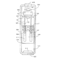
図1に本発明の環状の発電コイル(104)の内部で柱形磁石(107)とカップリングし、外部で外側導磁体(108)とカップリングする蓄電装置の実施例の構造模式図を示す。
図2に図1の断面図を示す。
図1、図2の主な構成は下記の通りである。
FIG. 1 shows a structural schematic diagram of an embodiment of a power storage device that is coupled to a columnar magnet (107) inside an annular power generation coil (104) of the present invention and is coupled to an outer magnetic conductor (108) outside. .
FIG. 2 shows a cross-sectional view of FIG.
The main configuration of FIGS. 1 and 2 is as follows.
ハウジング(100):弱導磁性および弱導電性材料により構成され、中空の円筒形を呈し、かつ内部の一端は内部に向かって一つの環状巻線コネクタ(101)を延伸し、その末端は延伸して環状の発電コイル(104)と連結し、その環状巻線コネクタ(101)とハウジング(100)の内孔との間に環状空間(103)を備え、環状巻線コネクタ(101)の中心に円孔状空間(102)を備え、環状の発電コイル(104)に出力導線(105)を設けることにより、環状の発電コイル(104)の発電電気エネルギーを整流充電回路(300)へ伝送し、更に整流充電回路(300)の出力端により蓄電装置(310)の陽極端へ伝送し、また蓄電装置(310)の正極端によりハウジング(100)に設置される正極の入出力端(410)と負極の入出力端(420)へ伝送する。 Housing (100): Constructed of weakly magnetic and weakly conductive material, has a hollow cylindrical shape, and one end of the inside extends one annular winding connector (101) toward the inside, the end of which extends The annular power generation coil (104) is connected, and an annular space (103) is provided between the annular winding connector (101) and the inner hole of the housing (100). Is provided with a circular space (102) and an output power wire (105) is provided in the annular power generation coil (104), thereby transmitting the generated electrical energy of the annular power generation coil (104) to the rectification charging circuit (300). In addition, the input and output of the positive electrode that is transmitted to the anode end of the power storage device (310) by the output end of the rectification charging circuit (300) and installed in the housing (100) by the positive end of the power storage device (310). (410) and transmitted to the input and output terminals of the negative electrode (420).
モーションブロックアセンブリ(106):弱導磁性および弱導電性材料により構成され、モーションブロックのカップ構造(110)を備え、外側導磁体(108)と結合し、モーションブロックのカップ構造(110)の中にモーションブロックの中柱(109)と結合する柱形磁石(107)を設け、かつモーションブロックの中柱(109)の周りはモーションブロックのカップ構造(110)とモーションブロック内部の環状空間(111)を形成することにより、環状の発電コイル(104)と環状巻線コネクタ(101)を相対的に軸方向に変位させ、かつ環状巻線コネクタ(101)の円孔状空間(102)と柱形磁石(107)、モーションブロックの中柱(109)を相対的に軸方向に変位させる。 Motion block assembly (106): composed of weakly conductive and weakly conductive material, comprising a motion block cup structure (110), coupled to an outer magnetic body (108), and in the motion block cup structure (110) Is provided with a columnar magnet (107) coupled to the middle pillar (109) of the motion block, and around the middle pillar (109) of the motion block is a cup structure (110) of the motion block and an annular space (111) inside the motion block. ), The annular power generation coil (104) and the annular winding connector (101) are relatively displaced in the axial direction, and the annular space (102) and the column of the annular winding connector (101) are formed. The shape magnet (107) and the middle pillar (109) of the motion block are relatively displaced in the axial direction.
環状巻線コネクタ(101)の円孔状空間(102)とハウジング(100)内壁との間に第一バッファー体(112)を設置し、モーションブロックアセンブリ(106)の中心柱体(109)と柱形磁石(107)と外側導磁体(108)が軸方向に変位するとき、緩衝する。 A first buffer body (112) is installed between the circular space (102) of the annular winding connector (101) and the inner wall of the housing (100), and the central column body (109) of the motion block assembly (106) When the columnar magnet (107) and the outer conductor (108) are displaced in the axial direction, they are buffered.
上述した柱形磁石(107)は外側導磁体(108)が軸方向に往復振動し、環状の発電コイル(104)を通過するとき、環状の発電コイル(104)が発電効果を発揮する。 In the columnar magnet (107) described above, when the outer magnetic conductor (108) reciprocally vibrates in the axial direction and passes through the annular power generation coil (104), the annular power generation coil (104) exhibits a power generation effect.
整流充電回路(300):環状の発電コイル(104)の発電電気エネルギーを整流し、蓄電装置(310)に対して電気エネルギーを注入する回路装置であり、電気機械や固体電子素子や整流装置により構成される。 Rectification and charging circuit (300): A circuit device that rectifies the generated electric energy of the annular power generation coil (104) and injects the electric energy into the power storage device (310). Composed.
蓄電装置(310):充放電可能な二次電池またはスパーキャパシタまたはコンデンサにより構成され、整流充電回路(300)から来る電気エネルギーを貯蔵し、または正極の入出力端(410)や負極の入出力端(420)により電気エネルギーを入力する。 Power storage device (310): constituted by a chargeable / dischargeable secondary battery, a super capacitor or a capacitor, stores electrical energy coming from the rectifying and charging circuit (300), or input / output terminal (410) of the positive electrode or input / output of the negative electrode Electrical energy is input through the end (420).
正極の入出力端(410):ターミナルヘッド、端子、プラグ、または、ソケットにより構成され、ハウジング(100)に設置され、整流充電回路(300)の正極端に接続され、外部に対して出力し、または電気エネルギーを入力する。 Positive input / output terminal (410): a terminal head, a terminal, a plug, or a socket, installed in the housing (100), connected to the positive terminal of the rectification charging circuit (300), and outputs to the outside Or enter electrical energy.
負極の入出力端(420):ターミナルヘッド、端子、プラグ、または、ソケットにより構成され、ハウジング(100)に設置され、整流充電回路(300)の負極端に接続され、外部に対して出力し、または電気エネルギーを入力する。 Negative input / output terminal (420): a terminal head, a terminal, a plug, or a socket, which is installed in the housing (100), connected to the negative terminal of the rectification charging circuit (300), and outputs to the outside. Or enter electrical energy.
ハウジング(100)のハウジング内部の円筒空間(114)とモーションブロックアセンブリ(106)の周辺を相対的に軸方向に変位させ、かつモーションブロックアセンブリ(106)とハウジング(100)の内部にある円筒空間(114)に内壁との間に第二バッファー体(113)を設置し、モーションブロックアセンブリ(106)が軸方向に変位するとき、緩衝する。 The cylindrical space (114) inside the housing of the housing (100) and the periphery of the motion block assembly (106) are relatively axially displaced, and the cylindrical space is inside the motion block assembly (106) and the housing (100). A second buffer body (113) is installed between the inner wall and the inner wall at (114), and cushions when the motion block assembly (106) is displaced in the axial direction.
(第2実施形態)
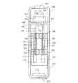
図3に本発明の環状の発電コイル(104)内部で柱形磁石(107)とカップリングし、外部で柱形磁石(107)と相対的に同じ極性である外側磁石(117)の蓄電装置とカップリングする実施例の構造模式図を示す。
図3の断面図は図2と同じである。
図3の主な構成は下記の通りである。
(Second Embodiment)
FIG. 3 shows a power storage device of an outer magnet (117) that is coupled to the columnar magnet (107) inside the annular power generation coil (104) of the present invention and that has the same polarity as the columnar magnet (107) outside. The structure schematic diagram of the Example which couples with is shown.
The sectional view of FIG. 3 is the same as FIG.
The main configuration of FIG. 3 is as follows.
ハウジング(100):弱導磁性および弱導電性材料により構成され、中空の円筒形を呈し、かつ内部の一端は内部に向かって一つの環状巻線コネクタ(101)を延伸し、その末端は延伸して環状の発電コイル(104)と連結し、その環状巻線コネクタ(101)とハウジング(100)の内孔との間に環状空間(103)を備え、環状巻線コネクタ(101)の中心に円孔状空間(102)を備え、環状の発電コイル(104)に出力導線(105)を設けることにより、環状の発電コイル(104)の発電電気エネルギーを整流充電回路(300)へ伝送し、更に整流充電回路(300)の出力端により蓄電装置(310)の陽極端へ伝送し、また蓄電装置(310)の正極端によりハウジング(100)に設置される正極の入出力端(410)と負極の入出力端(420)へ伝送する。 Housing (100): Constructed of weakly magnetic and weakly conductive material, has a hollow cylindrical shape, and one end of the inside extends one annular winding connector (101) toward the inside, the end of which extends The annular power generation coil (104) is connected, and an annular space (103) is provided between the annular winding connector (101) and the inner hole of the housing (100). Is provided with a circular space (102) and an output power wire (105) is provided in the annular power generation coil (104), thereby transmitting the generated electrical energy of the annular power generation coil (104) to the rectification charging circuit (300). In addition, the input and output of the positive electrode that is transmitted to the anode end of the power storage device (310) by the output end of the rectification charging circuit (300) and installed in the housing (100) by the positive end of the power storage device (310). (410) and transmitted to the input and output terminals of the negative electrode (420).
モーションブロックアセンブリ(106):弱導磁性および弱導電性材料により構成され、モーションブロックのカップ構造(110)を備え、外側磁石(117)と結合し、モーションブロックのカップ構造(110)の中にモーションブロックの中柱(109)と結合する柱形磁石(107)を設け、かつモーションブロックの中柱(109)の周りはモーションブロックのカップ構造(110)とモーションブロック内部の環状空間(111)を形成することにより、環状の発電コイル(104)と環状巻線コネクタ(101)を相対的に軸方向に変位させ、かつ環状巻線コネクタ(101)の円孔状空間(102)と柱形磁石(107)とモーションブロックの中柱(109)を相対的に軸方向に変位させる。 Motion block assembly (106): composed of weakly conductive and weakly conductive material, with motion block cup structure (110), coupled to outer magnet (117), into motion block cup structure (110) A columnar magnet (107) connected to the middle column (109) of the motion block is provided, and the motion block cup structure (110) and the annular space (111) inside the motion block are arranged around the middle column (109) of the motion block. The annular power generation coil (104) and the annular winding connector (101) are relatively displaced in the axial direction, and the annular space (102) and the columnar shape of the annular winding connector (101) are formed. The magnet (107) and the middle pillar (109) of the motion block are relatively displaced in the axial direction.
環状巻線コネクタ(101)の円孔状空間(102)とハウジング(100)内壁との間に第一バッファー体(112)を設置し、モーションブロックの中柱(109)と柱形磁石(107)と外側導磁体(108)が軸方向に変位するとき、緩衝する。 The first buffer body (112) is installed between the circular hole space (102) of the annular winding connector (101) and the inner wall of the housing (100), and the middle column (109) of the motion block and the columnar magnet (107). ) And the outer magnetic body (108) are buffered when displaced in the axial direction.
上述した柱形磁石(107)は外側磁石(117)が軸方向に往復振動し、環状の発電コイル(104)を通過するとき、環状の発電コイル(104)が発電効果を発揮する。 In the columnar magnet (107) described above, when the outer magnet (117) reciprocally vibrates in the axial direction and passes through the annular power generation coil (104), the annular power generation coil (104) exhibits a power generation effect.
整流充電回路(300):環状の発電コイル(104)の発電電気エネルギーを整流し、蓄電装置(310)に対して電気エネルギーを注入する回路装置であり、電気機械や固体電子素子や整流装置により構成される。 Rectification and charging circuit (300): A circuit device that rectifies the generated electric energy of the annular power generation coil (104) and injects the electric energy into the power storage device (310). Composed.
蓄電装置(310):充放電可能な二次電池またはスパーキャパシタまたはコンデンサにより構成され、整流充電回路(300)から来る電気エネルギーを貯蔵し、または正極の入出力端(410)や負極の入出力端(420)により電気エネルギーを入力する。 Power storage device (310): constituted by a chargeable / dischargeable secondary battery, a super capacitor or a capacitor, stores electrical energy coming from the rectifying and charging circuit (300), or input / output terminal (410) of the positive electrode or input / output of the negative electrode Electrical energy is input through the end (420).
正極の入出力端(410):ターミナルヘッド、端子、プラグ、または、ソケットにより構成され、ハウジング(100)に設置され、整流充電回路(300)の正極端に接続され、外部に対して出力し、または電気エネルギーを入力する。 Positive input / output terminal (410): a terminal head, a terminal, a plug, or a socket, installed in the housing (100), connected to the positive terminal of the rectification charging circuit (300), and outputs to the outside Or enter electrical energy.
負極の入出力端(420):ターミナルヘッド、端子、プラグ、または、ソケットにより構成され、ハウジング(100)に設置され、整流充電回路(300)の負極端に接続され、外部に対して出力し、または電気エネルギーを入力する。 Negative input / output terminal (420): a terminal head, a terminal, a plug, or a socket, which is installed in the housing (100), connected to the negative terminal of the rectification charging circuit (300), and outputs to the outside. Or enter electrical energy.
ハウジング(100)のハウジング内部の円筒空間(114)とモーションブロックアセンブリ(106)の周辺を相対的に軸方向に変位させ、かつモーションブロックアセンブリ(106)とハウジング(100)の内部にある円筒空間(114)に内壁との間に第二バッファー体(113)を設置し、モーションブロックアセンブリ(106)が軸方向に変位するとき、緩衝する。
柱形磁石(107)と柱形磁石(207)は、環状の発電コイル(104)の磁極面に相対して同極性であることを含む。または図4に示す通りである。
The cylindrical space (114) inside the housing of the housing (100) and the periphery of the motion block assembly (106) are relatively axially displaced, and the cylindrical space is inside the motion block assembly (106) and the housing (100). A second buffer body (113) is installed between the inner wall and the inner wall at (114), and cushions when the motion block assembly (106) is displaced in the axial direction.
It is included that the columnar magnet (107) and the columnar magnet (207) have the same polarity relative to the magnetic pole surface of the annular power generation coil (104). Or as shown in FIG.
柱形磁石(107)と柱形磁石(207)は、環状の発電コイル(104)の磁極面と相対的に異なる極性であることを含む。図4に本発明の環状の発電コイル(104)の内部で柱形磁石(107)とカップリングし、外部で柱形磁石(107)と相対的に異なる極性である外側磁石(117)の蓄電装置とカップリングする実施例の構造模式図を示す。図4の断面図は図2と同じである。 It is included that the columnar magnet (107) and the columnar magnet (207) have different polarities from the magnetic pole surface of the annular power generation coil (104). FIG. 4 shows the electrical storage of the outer magnet (117) which is coupled to the columnar magnet (107) inside the annular power generation coil (104) of the present invention and which has a polarity relatively different from that of the columnar magnet (107) outside. The structural schematic diagram of the Example coupled with an apparatus is shown. The cross-sectional view of FIG. 4 is the same as FIG.
(第3実施形態)
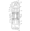
図5に本発明は複数段の環状の発電コイル(104)、(204)により構成され、環状の発電コイル(104)、(204)の内部で柱形磁石(107)、(207)とカップリングし、外部で外側導磁体(108)、(208)とカップリングする蓄電装置の実施例の構造模式図を示す。
図5の断面図は図2と同じである。
図5の主な構成は下記の通りである。
(Third embodiment)
In FIG. 5, the present invention is composed of a plurality of annular power generation coils (104) and (204). Columnar magnets (107) and (207) and cups are formed inside the annular power generation coils (104) and (204). The structure schematic diagram of the Example of the electrical storage apparatus which rings and couple | bonds with the outside magnetic conductors (108) and (208) outside is shown.
The cross-sectional view of FIG. 5 is the same as FIG.
The main configuration of FIG. 5 is as follows.
ハウジング(100):弱導磁性および弱導電性材料により構成され、中空の円筒形を呈し、かつ内部の一端は内部に向かって一つの環状巻線コネクタ(101)を延伸し、その末端は延伸して環状の発電コイル(104)と結合し、更に環状巻線コネクタ(201)と結合し、また延伸して環状の発電コイル(204)と結合し、その環状巻線コネクタ(101)とハウジング(100)の内孔との間に環状空間(103)を備え、環状の発電コイル(104)、(204)を同極になるように並列接続し、または直列接続することにより発電電圧を加え、出力導線(105)を設けることにより、環状の発電コイル(104)、(204)の発電電気エネルギーを整流充電回路(300)へ伝送し、更に整流充電回路(300)の出力端により蓄電装置(310)の陽極端へ伝送し、また蓄電装置(310)の正極端によりハウジング(100)に設置される正極の入出力端(410)と負極の入出力端(420)へ伝送する。 Housing (100): Constructed of weakly magnetic and weakly conductive material, has a hollow cylindrical shape, and one end of the inside extends one annular winding connector (101) toward the inside, the end of which extends Then, it couple | bonds with the cyclic | annular generator coil (104), and also couple | bonds with the cyclic | annular winding connector (201), and also extends | stretches and couple | bonds with the cyclic | annular generator coil (204), the cyclic | annular winding connector (101) and housing An annular space (103) is provided between the inner hole of (100), and the annular power generating coils (104) and (204) are connected in parallel so as to have the same polarity, or the generated voltage is applied by connecting them in series. By providing the output conductor (105), the generated electric energy of the annular power generation coils (104), (204) is transmitted to the rectification charging circuit (300), and the output terminal of the rectification charging circuit (300) From the positive electrode input / output terminal (410) and the negative electrode input / output terminal (420) installed in the housing (100) by the positive electrode terminal of the power storage device (310). To do.
モーションブロックアセンブリ(206):弱導磁性および弱導電性材料により構成され、モーションブロックのカップ構造(110)を備え、外側導磁体(108)と結合し、またカップ構造の分割リング(210)と再結合し、更に延伸して外側導磁体(208)と結合し、モーションブロックのカップ構造(110)の中にモーションブロックの中柱(109)と結合する柱形磁石(107)を設け、かつモーションブロックの中柱(209)と結合し、更に延伸して柱形磁石(207)と結合し、かつモーションブロックの中柱(109)の周りはモーションブロックのカップ構造(110)とモーションブロック内部の環状空間(111)を形成することにより、環状の発電コイル(104)、(204)と環状巻線コネクタ(201)と環状巻線コネクタ(101)を相対的に軸方向に変位させ、かつ環状巻線コネクタ(101)と環状巻線コネクタ(201)の円孔状空間(102)と柱形磁石(107)、(207)、モーションブロックの中柱(109)、(209)を相対的に軸方向に変位させる。 Motion block assembly (206): composed of weakly conductive and weakly conductive material, comprising a motion block cup structure (110), coupled to the outer conductor (108), and a cup structure split ring (210); Providing a columnar magnet (107) for recombination, further stretching and coupling with the outer conductor (208), coupling the motion block center column (109) in the motion block cup structure (110); and Combined with the middle block (209) of the motion block, and further extended to couple with the columnar magnet (207), and around the middle column (109) of the motion block, the cup structure (110) of the motion block and the inside of the motion block By forming the annular space (111), the annular power generation coils (104), (204) and the annular winding connector (2 1) and the annular winding connector (101) are relatively displaced in the axial direction, and the annular space (102) and the columnar magnet (107) of the annular winding connector (101) and the annular winding connector (201). ), (207), and the middle pillars (109), (209) of the motion block are relatively displaced in the axial direction.
環状巻線コネクタ(101)の円孔状空間(102)とハウジング(100)内壁との間に第一バッファー体(112)を設置し、モーションブロックの中柱(109)、(209)と柱形磁石(107)、(207)と外側導磁体(108)、(208)が軸方向に変位するとき、緩衝する。 The first buffer body (112) is installed between the circular hole space (102) of the annular winding connector (101) and the inner wall of the housing (100), and the middle pillars (109), (209) and pillars of the motion block are arranged. When the shape magnets (107) and (207) and the outer magnetic conductors (108) and (208) are displaced in the axial direction, they are buffered.
上述した柱形磁石(107)と柱形磁石(207)を通してモーションブロックの中柱(209)を隔てる間隔と環状の発電コイル(104)と環状の発電コイル(204)を通して環状巻線コネクタ(201)を隔てる間隔は、柱形磁石(107)と柱形磁石(207)と外側導磁体(108)と外側導磁体(208)が軸方向に往復振動し、環状の発電コイル(104)と環状の発電コイル(204)を通過するとき、環状の発電コイル(104)と環状の発電コイル(204)が同位相の電圧を作る。 The space between the columnar magnet (107) and the columnar magnet (207) separating the middle column (209) of the motion block, and the annular winding connector (201) through the annular generator coil (104) and the annular generator coil (204). ), The columnar magnet (107), the columnar magnet (207), the outer conductor (108), and the outer conductor (208) reciprocate in the axial direction so that the annular power generation coil (104) When passing through the power generating coil (204), the annular power generating coil (104) and the annular power generating coil (204) generate voltages having the same phase.
整流充電回路(300):環状の発電コイル(104)と環状の発電コイル(204)の発電電気エネルギーを整流し、蓄電装置(310)に対して電気エネルギーを注入する回路装置であり、電気機械や固体電子素子や整流装置により構成される。 Rectification and charging circuit (300): a circuit device that rectifies the generated electrical energy of the annular power generation coil (104) and the annular power generation coil (204) and injects the electrical energy into the power storage device (310), and is an electric machine Or a solid electronic element or a rectifier.
蓄電装置(310):充放電可能な二次電池またはスパーキャパシタまたはコンデンサにより構成され、整流充電回路(300)から来る電気エネルギーを貯蔵し、または正極の入出力端(410)や負極の入出力端(420)により電気エネルギーを入力する。 Power storage device (310): constituted by a chargeable / dischargeable secondary battery, a super capacitor or a capacitor, stores electrical energy coming from the rectifying and charging circuit (300), or input / output terminal (410) of the positive electrode or input / output of the negative electrode Electrical energy is input through the end (420).
正極の入出力端(410):ターミナルヘッド、端子、プラグ、または、ソケットにより構成され、ハウジング(100)に設置され、整流充電回路(300)の正極端に接続され、外部に対して出力し、または電気エネルギーを入力する。 Positive input / output terminal (410): a terminal head, a terminal, a plug, or a socket, installed in the housing (100), connected to the positive terminal of the rectification charging circuit (300), and outputs to the outside Or enter electrical energy.
負極の入出力端(420):ターミナルヘッド、端子、プラグ、または、ソケットにより構成され、ハウジング(100)に設置され、整流充電回路(300)の負極端に接続され、外部に対して出力し、または電気エネルギーを入力する。 Negative input / output terminal (420): a terminal head, a terminal, a plug, or a socket, which is installed in the housing (100), connected to the negative terminal of the rectification charging circuit (300), and outputs to the outside. Or enter electrical energy.
ハウジング(100)のハウジング内部の円筒空間(114)とモーションブロックアセンブリ(106)の周辺を相対的に軸方向に変位させ、かつモーションブロックアセンブリ(106)とハウジング(100)の内部にある円筒空間(114)に内壁との間に第二バッファー体(113)を設置し、モーションブロックアセンブリ(106)が軸方向に変位するとき、緩衝する。 The cylindrical space (114) inside the housing of the housing (100) and the periphery of the motion block assembly (106) are relatively axially displaced, and the cylindrical space is inside the motion block assembly (106) and the housing (100). A second buffer body (113) is installed between the inner wall and the inner wall at (114), and cushions when the motion block assembly (106) is displaced in the axial direction.
(第4実施形態)
図6に本発明は複数段の環状の発電コイル(104)、(204)により構成され、環状の発電コイル(104)、(204)の内部で柱形磁石(107)、(207)とカップリングし、外部で複数段の柱形磁石(107)と相対的に同じ極性である外側磁石(117)、(217)とカップリングする蓄電装置の実施例の構造模式図を示す。
図6の断面図と図2と同じである。
図6の主な構成は下記の通りである。
(Fourth embodiment)
In FIG. 6, the present invention is composed of a plurality of annular power generation coils (104) and (204). Columnar magnets (107) and (207) and cups are formed inside the annular power generation coils (104) and (204). The structure schematic diagram of the Example of the electrical storage apparatus which carries out a ring and couples with the outer magnets (117) and (217) which are relatively the same polarity as the multistage columnar magnet (107) outside is shown.
6 is the same as the cross-sectional view of FIG. 6 and FIG.
The main configuration of FIG. 6 is as follows.
ハウジング(100):弱導磁性および弱導電性材料により構成され、中空の円筒形を呈し、かつ内部の一端は内部に向かって一つの環状巻線コネクタ(101)を延伸し、その末端は延伸して環状の発電コイル(104)と結合し、更に環状巻線コネクタ(201)と結合し、また延伸して環状の発電コイル(204)と結合し、その環状巻線コネクタ(101)とハウジング(100)の内孔との間に環状空間(103)を備え、環状巻線コネクタ(101)の中心に円孔状空間(102)を備え、環状の発電コイル(104)、(204)を同極になるように並列接続し、または直列接続することにより発電電圧を加え、出力導線(105)を設けることにより、環状の発電コイル(104)、(204)の発電電気エネルギーを整流充電回路(300)へ伝送し、更に整流充電回路(300)の出力端により蓄電装置(310)の陽極端へ伝送し、また蓄電装置(310)の正極端によりハウジング(100)に設置される正極の入出力端(410)と負極の入出力端(420)へ伝送する。 Housing (100): Constructed of weakly magnetic and weakly conductive material, has a hollow cylindrical shape, and one end of the inside extends one annular winding connector (101) toward the inside, the end of which extends Then, it couple | bonds with the cyclic | annular generator coil (104), and also couple | bonds with the cyclic | annular winding connector (201), and also extends | stretches and couple | bonds with the cyclic | annular generator coil (204), the cyclic | annular winding connector (101) and housing An annular space (103) is provided between the inner hole of (100), a circular hole space (102) is provided at the center of the annular winding connector (101), and annular power generation coils (104), (204) are provided. The power generation voltage is applied by parallel connection or series connection so as to have the same polarity, and the output conductive wire (105) is provided to rectify the generated electrical energy of the annular power generation coils (104) and (204). It is transmitted to the electric circuit (300), further transmitted to the anode end of the power storage device (310) by the output end of the rectification charging circuit (300), and installed in the housing (100) by the positive end of the power storage device (310). The data is transmitted to the positive input / output terminal (410) and the negative input / output terminal (420).
モーションブロックアセンブリ(206):弱導磁性および弱導電性材料により構成され、モーションブロックのカップ構造(110)を備え、外側磁石(117)と結合し、またカップ構造の分割リング(210)と再結合し、更に延伸して外側磁石(217)と結合し、モーションブロックのカップ構造(110)の中にモーションブロックの中柱(109)と結合する柱形磁石(107)を設け、かつモーションブロックの中柱(209)と結合し、更に延伸して柱形磁石(207)と結合し、かつモーションブロックの中柱(109)の周りはモーションブロックのカップ構造(110)とモーションブロック内部の環状空間(111)を形成することにより、環状の発電コイル(104)、(204)と環状巻線コネクタ(201)と環状巻線コネクタ(101)を相対的に軸方向に変位させ、かつ環状巻線コネクタ(101)と環状巻線コネクタ(201)の円孔状空間(102)と柱形磁石(107)、(207)、モーションブロックの中柱(109)、(209)を相対的に軸方向に変位させる。 Motion block assembly (206): composed of weakly conductive and weakly conductive material, comprising motion block cup structure (110), coupled to outer magnet (117), and recombined with cup structure split ring (210). A columnar magnet (107) that couples with the outer column (217), couples with the outer magnet (217), couples with the middle column (109) of the motion block in the motion block cup structure (110), and the motion block It is connected to the center pillar (209) of the motion block, and is further extended to be connected to the columnar magnet (207), and the motion block cup structure (110) and the annular shape inside the motion block are arranged around the center pillar (109) of the motion block. By forming the space (111), the annular power generation coils (104), (204) and the annular winding connector (201 And the annular winding connector (101) are relatively axially displaced, and the annular space (102) and the columnar magnet (107) of the annular winding connector (101) and the annular winding connector (201), (207) The middle pillars (109) and (209) of the motion block are relatively displaced in the axial direction.
環状巻線コネクタ(101)の円孔状空間(102)とハウジング(100)内壁との間に第一バッファー体(112)を設置し、モーションブロックの中柱(109)、(209)と柱形磁石(107)、(207)と外側磁石(117)、(217)が軸方向に変位するとき、緩衝する。 The first buffer body (112) is installed between the circular hole space (102) of the annular winding connector (101) and the inner wall of the housing (100), and the middle pillars (109), (209) and pillars of the motion block are arranged. When the shape magnets (107) and (207) and the outer magnets (117) and (217) are displaced in the axial direction, they are buffered.
上述した柱形磁石(107)と柱形磁石(207)と外側磁石(117)と外側磁石(217)を通してモーションブロックの中柱(209)を隔てる間隔と環状の発電コイル(104)と環状の発電コイル(204)を通して環状巻線コネクタ(201)を隔てる間隔は、柱形磁石(107)と柱形磁石(207)と外側磁石(117)と外側磁石(217)が軸方向に往復振動し、環状の発電コイル(104)と環状の発電コイル(204)を通過するとき、環状の発電コイル(104)と環状の発電コイル(204)が同位相の電圧を作る。 The interval between the columnar magnet (107), the columnar magnet (207), the outer magnet (117) and the outer magnet (217) separating the middle column (209) of the motion block, the annular power generation coil (104) and the annular magnet The space separating the annular winding connector (201) through the generator coil (204) is such that the columnar magnet (107), the columnar magnet (207), the outer magnet (117), and the outer magnet (217) reciprocate in the axial direction. When passing through the annular power generating coil (104) and the annular power generating coil (204), the annular power generating coil (104) and the annular power generating coil (204) generate voltages having the same phase.
整流充電回路(300):環状の発電コイル(104)及び環状の発電コイル(204)の発電電気エネルギーを整流し、に対して蓄電装置(310)を注入する電気エネルギーの回路装置、電気機械及び固体電子素子及び整流装置により構成される。 Rectification and charging circuit (300): an electric energy circuit device that rectifies the generated electric energy of the annular power generation coil (104) and the annular power generation coil (204), and injects the power storage device (310) into the electrical power generation device, electric machine, and It is composed of a solid-state electronic element and a rectifier.
整流充電回路(300):環状の発電コイル(104)と環状の発電コイル(204)の発電電気エネルギーを整流し、蓄電装置(310)に対して電気エネルギーを注入する回路装置であり、電気機械や固体電子素子や整流装置により構成される。 Rectification and charging circuit (300): a circuit device that rectifies the generated electrical energy of the annular power generation coil (104) and the annular power generation coil (204) and injects the electrical energy into the power storage device (310), and is an electric machine Or a solid electronic element or a rectifier.
蓄電装置(310):充放電可能な二次電池またはスパーキャパシタまたはコンデンサにより構成され、整流充電回路(300)から来る電気エネルギーを貯蔵し、または正極の入出力端(410)や負極の入出力端(420)により電気エネルギーを入力する。 Power storage device (310): constituted by a chargeable / dischargeable secondary battery, a super capacitor or a capacitor, stores electrical energy coming from the rectifying and charging circuit (300), or input / output terminal (410) of the positive electrode or input / output of the negative electrode Electrical energy is input through the end (420).
正極の入出力端(410):ターミナルヘッド、端子、プラグ、または、ソケットにより構成され、ハウジング(100)に設置され、整流充電回路(300)の正極端に接続され、外部に対して出力し、または電気エネルギーを入力する。 Positive input / output terminal (410): a terminal head, a terminal, a plug, or a socket, installed in the housing (100), connected to the positive terminal of the rectification charging circuit (300), and outputs to the outside Or enter electrical energy.
負極の入出力端(420):ターミナルヘッド、端子、プラグ、または、ソケットにより構成され、ハウジング(100)に設置され、整流充電回路(300)の負極端に接続され、外部に対して出力し、または電気エネルギーを入力する。 Negative input / output terminal (420): a terminal head, a terminal, a plug, or a socket, which is installed in the housing (100), connected to the negative terminal of the rectification charging circuit (300), and outputs to the outside. Or enter electrical energy.
ハウジング(100)のハウジング内部の円筒空間(114)とモーションブロックアセンブリ(106)の周辺を相対的に軸方向に変位させ、かつモーションブロックアセンブリ(106)とハウジング(100)の内部にある円筒空間(114)に内壁との間に第二バッファー体(113)を設置し、モーションブロックアセンブリ(106)が軸方向に変位するとき、緩衝する。 The cylindrical space (114) inside the housing of the housing (100) and the periphery of the motion block assembly (106) are relatively axially displaced, and the cylindrical space is inside the motion block assembly (106) and the housing (100). A second buffer body (113) is installed between the inner wall and the inner wall at (114), and cushions when the motion block assembly (106) is displaced in the axial direction.
柱形磁石(107)と柱形磁石(207)の二者は、環状の発電コイル(104)の磁極面に相対して、外側磁石(117)と外側磁石(217)に相対的に環状の発電コイル(204)の磁極面に相対して同極性であることを含む。または図7に示す通りである。 The two of the columnar magnet (107) and the columnar magnet (207) are relatively annular to the outer magnet (117) and the outer magnet (217) relative to the magnetic pole surface of the annular power generation coil (104). Including the same polarity relative to the magnetic pole surface of the power generation coil (204). Or as shown in FIG.
柱形磁石(107)と柱形磁石(207)は、環状の発電コイル(104)の磁極面に相対して、及び外側磁石(117)と外側磁石(217)が環状の発電コイル(204)の磁極面に相対して異なる極性であることを含む。図7に本発明は複数段の環状の発電コイル(104)、(204)により構成され、環状の発電コイル(104)、(204)の内部で柱形磁石(107)、(207)とカップリングし、外部で複数段の柱形磁石(107)に相対して異なる極性の外側磁石(117)、(217)の蓄電装置とカップリングする実施例の構造模式図を示す。図7の断面図と図2と同じである。 The columnar magnet (107) and the columnar magnet (207) are opposed to the magnetic pole surface of the annular power generation coil (104), and the outer magnet (117) and the outer magnet (217) are annular in the power generation coil (204). Including different polarities relative to the magnetic pole face. In FIG. 7, the present invention includes a plurality of stages of annular power generation coils (104) and (204), and columnar magnets (107) and (207) and cups inside the annular power generation coils (104) and (204). The structure schematic diagram of the Example which carries out a ring and couples with the electrical storage apparatus of the outer magnets (117) and (217) of a different polarity with respect to the columnar magnet (107) of several steps outside is shown. 7 is the same as the cross-sectional view of FIG. 7 and FIG.
前述した図5の実施例に設置される柱形磁石(107)、柱形磁石(207)、環状の発電コイル(104)、環状の発電コイル(204)、外側導磁体(108)、外側導磁体(208)は、全て2個以上により構成される。 The columnar magnet (107), the columnar magnet (207), the annular power generation coil (104), the annular power generation coil (204), the outer magnetic conductor (108), the outer conductor, which are installed in the embodiment of FIG. The magnetic bodies (208) are all composed of two or more.
前述した図6、7の実施例に設置される柱形磁石(107)、柱形磁石(207)、環状の発電コイル(104)、環状の発電コイル(204)、外側磁石(117)、外側磁石(217)は、全て2個以上により構成される。 The columnar magnet (107), the columnar magnet (207), the annular power generation coil (104), the annular power generation coil (204), the outer magnet (117), and the outside installed in the embodiment of FIGS. The magnets (217) are all composed of two or more.
前述した図5の実施例に設置される柱形磁石(107)、柱形磁石(207)、外側導磁体(108)、外側導磁体(208)、全て2個以上により構成され、かつ環状の発電コイル(104)は1個により構成される。 Each of the columnar magnet (107), the columnar magnet (207), the outer magnetic conductor (108), and the outer magnetic conductor (208) installed in the embodiment of FIG. The power generation coil (104) is composed of one piece.
前述した図6、7の実施例に設置される柱形磁石(107)、柱形磁石(207)、外側磁石(117)、外側磁石(217)は、全て2個以上により構成され、かつ環状の発電コイル(104)は1個により構成される。 The columnar magnet (107), the columnar magnet (207), the outer magnet (117), and the outer magnet (217) installed in the embodiment of FIGS. The power generating coil (104) is composed of one piece.
本実施例のインナーポストと外環状磁気モーションブロックを備える振動発電する蓄電装置のハウジング(100)と正極の入出力端(410)と負極の入出力端(420)は、従来のバッテリーと相容れる出力導電インタフェース及び形状および構造に製造され、またはニーズによって製造される各種構造を含む。 The housing (100) of the vibration accumulator that includes the inner post and the outer annular magnetic motion block of this embodiment, the positive input / output terminal (410) and the negative input / output terminal (420) are compatible with the conventional battery. Output conductive interfaces and shapes and structures manufactured, or include various structures manufactured according to needs.
(100):ハウジング
(101):環状巻線コネクタ
(102):円孔状空間
(103):環状空間
(104)、(204):環状の発電コイル
(105):出力導線
(106)、(206):モーションブロックアセンブリ
(107)、(207):柱形磁石
(108)、(208):外側導磁体
(109)、(209):モーションブロックの中柱
(110):モーションブロックのカップ構造
(111):モーションブロック内部の環状空間
(112):第一バッファー体
(113):第二バッファー体
(114):ハウジング内部の円筒空間
(117)、(217):外側磁石
(201):環状巻線コネクタ
(210):カップ構造の分割リング
(300):整流充電回路
(310):蓄電装置
(410):正極の入出力端
(420):負極の入出力端
(100): Housing (101): Annular winding connector (102): Circular space (103): Annular space (104), (204): An annular power generation coil (105): Output conductor (106), ( 206): Motion block assembly (107), (207): Columnar magnet (108), (208): Outer magnetic conductor (109), (209): Middle column of motion block (110): Cup structure of motion block (111): annular space inside motion block (112): first buffer body (113): second buffer body (114): cylindrical space (117) inside housing (217): outer magnet (201): annular Winding connector (210): Split ring with cup structure (300): Rectification charging circuit (310): Power storage device (410): Input / output terminal of positive electrode (42 ): The negative electrode of the input and output ends
Claims (12)
ハウジング(100)は、弱導磁性および弱導電性材料により構成され、中空の円筒形を呈し、かつ内部の一端は内部に向かって一つの環状巻線コネクタ(101)を延伸し、その末端は延伸して環状の発電コイル(104)と連結し、その環状巻線コネクタ(101)とハウジング(100)の内孔との間に環状空間(103)を備え、環状巻線コネクタ(101)の中心に円孔状空間(102)を備え、環状の発電コイル(104)に出力導線(105)を設けることにより、環状の発電コイル(104)の発電電気エネルギーを整流充電回路(300)へ伝送し、更に整流充電回路(300)の出力端により蓄電装置(310)の陽極端へ伝送し、また蓄電装置(310)の正極端によりハウジング(100)に設置される正極の入出力端(410)と負極の入出力端(420)へ伝送し、
モーションブロックアセンブリ(106)は、弱導磁性および弱導電性材料により構成され、モーションブロックのカップ構造(110)を備え、外側導磁体(108)と結合し、モーションブロックのカップ構造(110)の中にモーションブロックの中柱(109)と結合する柱形磁石(107)を設け、かつモーションブロックの中柱(109)の周りはモーションブロックのカップ構造(110)とモーションブロック内部の環状空間(111)を形成することにより、環状の発電コイル(104)と環状巻線コネクタ(101)を相対的に軸方向に変位させ、かつ環状巻線コネクタ(101)の円孔状空間(102)と柱形磁石(107)、モーションブロックの中柱(109)を相対的に軸方向に変位させ、
環状巻線コネクタ(101)の円孔状空間(102)とハウジング(100)内壁との間に第一バッファー体(112)を設置し、モーションブロックアセンブリ(106)の中心柱体(109)と柱形磁石(107)と外側導磁体(108)が軸方向に変位するとき、緩衝し、
上述した柱形磁石(107)は外側導磁体(108)が軸方向に往復振動し、環状の発電コイル(104)を通過するとき、環状の発電コイル(104)が発電効果を発揮し、
整流充電回路(300)は、環状の発電コイル(104)の発電電気エネルギーを整流し、蓄電装置(310)に対して電気エネルギーを注入する回路装置であり、電気機械や固体電子素子や整流装置により構成され、
蓄電装置(310)は、充放電可能な二次電池またはスパーキャパシタまたはコンデンサにより構成され、整流充電回路(300)から来る電気エネルギーを貯蔵し、または正極の入出力端(410)や負極の入出力端(420)により電気エネルギーを入力し、
正極の入出力端(410)は、ターミナルヘッド、端子、プラグ、または、ソケットにより構成され、ハウジング(100)に設置され、整流充電回路(300)の正極端に接続され、外部に対して出力し、または電気エネルギーを入力し、
負極の入出力端(420)は、ターミナルヘッド、端子、プラグ、または、ソケットにより構成され、ハウジング(100)に設置され、整流充電回路(300)の負極端に接続され、外部に対して出力し、または電気エネルギーを入力し、
ハウジング(100)のハウジング内部の円筒空間(114)とモーションブロックアセンブリ(106)の周辺を相対的に軸方向に変位させ、かつモーションブロックアセンブリ(106)とハウジング(100)の内部にある円筒空間(114)に内壁との間に第二バッファー体(113)を設置し、モーションブロックアセンブリ(106)が軸方向に変位するとき、緩衝することを特徴とするインナーポストと外環状磁気モーションブロックを備える振動発電可能な蓄電装置。 It is provided with a columnar magnet of a magnetic pole having a cylindrical shape and a different polarity in the axial direction, and covered with an outer magnetic conductor outside thereof, and both are coupled to the motion block assembly (106) and arranged adjacent to each other coaxially. By constructing the magnetic path, it is displaced in the axial direction synchronously, the outer diameter of the columnar magnet is smaller than the inner diameter of the outer magnetic conductor, has one annular gap, and passes through the annular power generation coil. When the coil reciprocates in the axial direction and relatively oscillates in the axial direction, due to the effect of Lenz's law, the annular power generation coil creates electrical energy, and further stores the electrical energy in the power storage device via the rectification charging circuit. Install the positive input / output terminal and negative input / output terminal of the power storage device as the electrical energy input / output interface,
The housing (100) is made of weakly conductive and weakly conductive material, has a hollow cylindrical shape, and one end of the inside extends one annular winding connector (101) toward the inside, and its end is The ring-shaped power generation coil (104) is extended and connected, and an annular space (103) is provided between the ring-winding connector (101) and the inner hole of the housing (100). A circular hole-shaped space (102) is provided in the center, and the output power (105) is provided in the annular power generation coil (104), thereby transmitting the generated electrical energy of the annular power generation coil (104) to the rectification charging circuit (300). In addition, transmission to the anode end of the power storage device (310) is performed by the output end of the rectification charging circuit (300), and input / output of the positive electrode installed in the housing (100) is performed by the positive end of the power storage device (310). Transmitting end and (410) input and output ends of the negative electrode to the (420),
The motion block assembly (106) is composed of a weakly conductive and weakly conductive material, includes a motion block cup structure (110), is coupled to the outer magnetic body (108), and is connected to the motion block cup structure (110). A columnar magnet (107) coupled to the middle column (109) of the motion block is provided therein, and around the middle column (109) of the motion block, the motion block cup structure (110) and the annular space inside the motion block ( 111), the annular power generation coil (104) and the annular winding connector (101) are relatively displaced in the axial direction, and the annular space (102) of the annular winding connector (101) The columnar magnet (107) and the middle column (109) of the motion block are relatively displaced in the axial direction,
A first buffer body (112) is installed between the circular space (102) of the annular winding connector (101) and the inner wall of the housing (100), and the central column body (109) of the motion block assembly (106) When the columnar magnet (107) and the outer conductor (108) are displaced in the axial direction, they are buffered,
In the columnar magnet (107) described above, when the outer conductor (108) reciprocates in the axial direction and passes through the annular power generation coil (104), the annular power generation coil (104) exhibits a power generation effect,
The rectification charging circuit (300) is a circuit device that rectifies the electric energy generated by the annular power generation coil (104) and injects the electric energy into the power storage device (310). Composed of
The power storage device (310) is configured by a rechargeable secondary battery, a super capacitor, or a capacitor, stores electrical energy coming from the rectifying and charging circuit (300), or inputs / outputs the positive electrode (410) or the negative electrode. Electric energy is input through the output terminal (420),
The positive input / output terminal (410) is configured by a terminal head, a terminal, a plug, or a socket, is installed in the housing (100), is connected to the positive terminal of the rectification charging circuit (300), and outputs to the outside. Or enter electrical energy,
The negative input / output terminal (420) includes a terminal head, a terminal, a plug, or a socket, is installed in the housing (100), is connected to the negative terminal of the rectification charging circuit (300), and outputs to the outside. Or enter electrical energy,
The cylindrical space (114) inside the housing of the housing (100) and the periphery of the motion block assembly (106) are relatively axially displaced, and the cylindrical space is inside the motion block assembly (106) and the housing (100). The second buffer body (113) is installed between the inner wall and the inner wall at (114), and the inner post and the outer annular magnetic motion block are buffered when the motion block assembly (106) is displaced in the axial direction. A power storage device capable of vibration power generation.
ハウジング(100)は、弱導磁性および弱導電性材料により構成され、中空の円筒形を呈し、かつ内部の一端は内部に向かって一つの環状巻線コネクタ(101)を延伸し、その末端は延伸して環状の発電コイル(104)と連結し、その環状巻線コネクタ(101)とハウジング(100)の内孔との間に環状空間(103)を備え、環状巻線コネクタ(101)の中心に円孔状空間(102)を備え、環状の発電コイル(104)に出力導線(105)を設けることにより、環状の発電コイル(104)の発電電気エネルギーを整流充電回路(300)へ伝送し、更に整流充電回路(300)の出力端により蓄電装置(310)の陽極端へ伝送し、また蓄電装置(310)の正極端によりハウジング(100)に設置される正極の入出力端(410)と負極の入出力端(420)へ伝送し、
モーションブロックアセンブリ(106)は、弱導磁性および弱導電性材料により構成され、モーションブロックのカップ構造(110)を備え、外側磁石(117)と結合し、モーションブロックのカップ構造(110)の中にモーションブロックの中柱(109)と結合する柱形磁石(107)を設け、かつモーションブロックの中柱(109)の周りはモーションブロックのカップ構造(110)とモーションブロック内部の環状空間(111)を形成することにより、環状の発電コイル(104)と環状巻線コネクタ(101)を相対的に軸方向に変位させ、かつ環状巻線コネクタ(101)の円孔状空間(102)と柱形磁石(107)とモーションブロックの中柱(109)を相対的に軸方向に変位させ、
環状巻線コネクタ(101)の円孔状空間(102)とハウジング(100)内壁との間に第一バッファー体(112)を設置し、モーションブロックの中柱(109)と柱形磁石(107)と外側導磁体(108)が軸方向に変位するとき、緩衝し、
上述した柱形磁石(107)は外側磁石(117)が軸方向に往復振動し、環状の発電コイル(104)を通過するとき、環状の発電コイル(104)が発電効果を発揮し、
整流充電回路(300)は、環状の発電コイル(104)の発電電気エネルギーを整流し、蓄電装置(310)に対して電気エネルギーを注入する回路装置であり、電気機械や固体電子素子や整流装置により構成され、
蓄電装置(310)は、充放電可能な二次電池またはスパーキャパシタまたはコンデンサにより構成され、整流充電回路(300)から来る電気エネルギーを貯蔵し、または正極の入出力端(410)や負極の入出力端(420)により電気エネルギーを入力し、
正極の入出力端(410)は、ターミナルヘッド、端子、プラグ、または、ソケットにより構成され、ハウジング(100)に設置され、整流充電回路(300)の正極端に接続され、外部に対して出力し、または電気エネルギーを入力し、
負極の入出力端(420)は、ターミナルヘッド、端子、プラグ、または、ソケットにより構成され、ハウジング(100)に設置され、整流充電回路(300)の負極端に接続され、外部に対して出力し、または電気エネルギーを入力し、
ハウジング(100)のハウジング内部の円筒空間(114)とモーションブロックアセンブリ(106)の周辺を相対的に軸方向に変位させ、かつモーションブロックアセンブリ(106)とハウジング(100)の内部にある円筒空間(114)に内壁との間に第二バッファー体(113)を設置し、モーションブロックアセンブリ(106)が軸方向に変位するとき、緩衝し、
柱形磁石(107)と柱形磁石(207)は、環状の発電コイル(104)の磁極面に相対して同極性であることを含むことを特徴とする請求項1に記載の振動発電可能な蓄電装置。 Coupling with the columnar magnet (107) inside the annular power generation coil (104), and coupling with the power storage device of the outer magnet (117) having the same polarity as the columnar magnet (107) on the outside,
The housing (100) is made of weakly conductive and weakly conductive material, has a hollow cylindrical shape, and one end of the inside extends one annular winding connector (101) toward the inside, and its end is The ring-shaped power generation coil (104) is extended and connected, and an annular space (103) is provided between the ring-winding connector (101) and the inner hole of the housing (100). A circular hole-shaped space (102) is provided in the center, and the output power (105) is provided in the annular power generation coil (104), thereby transmitting the generated electrical energy of the annular power generation coil (104) to the rectification charging circuit (300). In addition, transmission to the anode end of the power storage device (310) is performed by the output end of the rectification charging circuit (300), and input / output of the positive electrode installed in the housing (100) is performed by the positive end of the power storage device (310). Transmitting end and (410) input and output ends of the negative electrode to the (420),
The motion block assembly (106) is composed of a weakly conductive and weakly conductive material, includes a motion block cup structure (110), couples to an outer magnet (117), and is located in the motion block cup structure (110). Is provided with a columnar magnet (107) coupled to the middle pillar (109) of the motion block, and around the middle pillar (109) of the motion block is a cup structure (110) of the motion block and an annular space (111) inside the motion block. ), The annular power generation coil (104) and the annular winding connector (101) are relatively displaced in the axial direction, and the annular space (102) and the column of the annular winding connector (101) are formed. Displace the shape magnet (107) and the middle pillar (109) of the motion block in the axial direction relatively,
The first buffer body (112) is installed between the circular hole space (102) of the annular winding connector (101) and the inner wall of the housing (100), and the middle column (109) of the motion block and the columnar magnet (107). ) And the outer magnetic conductor (108) are buffered when displaced in the axial direction,
In the columnar magnet (107) described above, when the outer magnet (117) reciprocally vibrates in the axial direction and passes through the annular power generation coil (104), the annular power generation coil (104) exhibits a power generation effect,
The rectification charging circuit (300) is a circuit device that rectifies the electric energy generated by the annular power generation coil (104) and injects the electric energy into the power storage device (310). Composed of
The power storage device (310) is configured by a rechargeable secondary battery, a super capacitor, or a capacitor, stores electrical energy coming from the rectifying and charging circuit (300), or inputs / outputs the positive electrode (410) or the negative electrode. Electric energy is input through the output terminal (420),
The positive input / output terminal (410) is configured by a terminal head, a terminal, a plug, or a socket, is installed in the housing (100), is connected to the positive terminal of the rectification charging circuit (300), and outputs to the outside. Or enter electrical energy,
The negative input / output terminal (420) includes a terminal head, a terminal, a plug, or a socket, is installed in the housing (100), is connected to the negative terminal of the rectification charging circuit (300), and outputs to the outside. Or enter electrical energy,
The cylindrical space (114) inside the housing of the housing (100) and the periphery of the motion block assembly (106) are relatively axially displaced, and the cylindrical space is inside the motion block assembly (106) and the housing (100). The second buffer body (113) is installed between the inner wall of (114) and the motion block assembly (106) is buffered when displaced axially,
The columnar magnet (107) and the columnar magnet (207) include the same polarity relative to the magnetic pole surface of the annular power generation coil (104), and can generate vibration power according to claim 1. Power storage device.
ハウジング(100)は、弱導磁性および弱導電性材料により構成され、中空の円筒形を呈し、かつ内部の一端は内部に向かって一つの環状巻線コネクタ(101)を延伸し、その末端は延伸して環状の発電コイル(104)と結合し、更に環状巻線コネクタ(201)と結合し、また延伸して環状の発電コイル(204)と結合し、その環状巻線コネクタ(101)とハウジング(100)の内孔との間に環状空間(103)を備え、環状の発電コイル(104)、(204)を同極になるように並列接続し、または直列接続することにより発電電圧を加え、出力導線(105)を設けることにより、環状の発電コイル(104)、(204)の発電電気エネルギーを整流充電回路(300)へ伝送し、更に整流充電回路(300)の出力端により蓄電装置(310)の陽極端へ伝送し、また蓄電装置(310)の正極端によりハウジング(100)に設置される正極の入出力端(410)と負極の入出力端(420)へ伝送し、
モーションブロックアセンブリ(206)は、弱導磁性および弱導電性材料により構成され、モーションブロックのカップ構造(110)を備え、外側導磁体(108)と結合し、またカップ構造の分割リング(210)と再結合し、更に延伸して外側導磁体(208)と結合し、モーションブロックのカップ構造(110)の中にモーションブロックの中柱(109)と結合する柱形磁石(107)を設け、かつモーションブロックの中柱(209)と結合し、更に延伸して柱形磁石(207)と結合し、かつモーションブロックの中柱(109)の周りはモーションブロックのカップ構造(110)とモーションブロック内部の環状空間(111)を形成することにより、環状の発電コイル(104)、(204)と環状巻線コネクタ(201)と環状巻線コネクタ(101)を相対的に軸方向に変位させ、かつ環状巻線コネクタ(101)と環状巻線コネクタ(201)の円孔状空間(102)と柱形磁石(107)、(207)、モーションブロックの中柱(109)、(209)を相対的に軸方向に変位させ、
環状巻線コネクタ(101)の円孔状空間(102)とハウジング(100)内壁との間に第一バッファー体(112)を設置し、モーションブロックの中柱(109)、(209)と柱形磁石(107)、(207)と外側導磁体(108)、(208)が軸方向に変位するとき、緩衝し、
上述した柱形磁石(107)と柱形磁石(207)を通してモーションブロックの中柱(209)を隔てる間隔と環状の発電コイル(104)と環状の発電コイル(204)を通して環状巻線コネクタ(201)を隔てる間隔は、柱形磁石(107)と柱形磁石(207)と外側導磁体(108)と外側導磁体(208)が軸方向に往復振動し、環状の発電コイル(104)と環状の発電コイル(204)を通過するとき、環状の発電コイル(104)と環状の発電コイル(204)が同位相の電圧を作り、
整流充電回路(300)は、環状の発電コイル(104)と環状の発電コイル(204)の発電電気エネルギーを整流し、蓄電装置(310)に対して電気エネルギーを注入する回路装置であり、電気機械や固体電子素子や整流装置により構成され、
蓄電装置(310)は、充放電可能な二次電池またはスパーキャパシタまたはコンデンサにより構成され、整流充電回路(300)から来る電気エネルギーを貯蔵し、または正極の入出力端(410)や負極の入出力端(420)により電気エネルギーを入力し、
正極の入出力端(410)は、ターミナルヘッド、端子、プラグ、または、ソケットにより構成され、ハウジング(100)に設置され、整流充電回路(300)の正極端に接続され、外部に対して出力し、または電気エネルギーを入力し、
負極の入出力端(420)は、ターミナルヘッド、端子、プラグ、または、ソケットにより構成され、ハウジング(100)に設置され、整流充電回路(300)の負極端に接続され、外部に対して出力し、または電気エネルギーを入力し、
ハウジング(100)のハウジング内部の円筒空間(114)とモーションブロックアセンブリ(106)の周辺を相対的に軸方向に変位させ、かつモーションブロックアセンブリ(106)とハウジング(100)の内部にある円筒空間(114)に内壁との間に第二バッファー体(113)を設置し、モーションブロックアセンブリ(106)が軸方向に変位するとき、緩衝することを特徴とする請求項1に記載の振動発電可能な蓄電装置。 It is composed of a plurality of annular power generation coils (104) and (204), coupled to the columnar magnets (107) and (207) inside the annular power generation coils (104) and (204), and outside on the outside. Coupling with the magnetic conductors (108), (208),
The housing (100) is made of weakly conductive and weakly conductive material, has a hollow cylindrical shape, and one end of the inside extends one annular winding connector (101) toward the inside, and its end is Stretched and coupled with the annular power generating coil (104), and further coupled with the annular winding connector (201), and stretched and coupled with the annular power generating coil (204), and the annular wound connector (101) An annular space (103) is provided between the inner hole of the housing (100), and the annular power generation coils (104) and (204) are connected in parallel so as to have the same polarity, or the generated voltage can be generated by connecting them in series. In addition, by providing the output lead wire (105), the generated electric energy of the annular power generation coils (104), (204) is transmitted to the rectification charging circuit (300), and further the output of the rectification charging circuit (300). Is transmitted to the anode terminal of the power storage device (310), and is transmitted to the positive input / output terminal (410) and the negative input / output terminal (420) installed in the housing (100) by the positive electrode terminal of the power storage device (310). And
The motion block assembly (206) is composed of a weakly conductive and weakly conductive material, includes a motion block cup structure (110), couples to the outer magnetic body (108), and also includes a cup structure split ring (210). A columnar magnet (107) that couples with the outer magnetic body (208) and couples with the middle column (109) of the motion block in the cup structure (110) of the motion block; In addition, it is coupled with the middle pillar (209) of the motion block, and further extended to couple with the columnar magnet (207), and around the middle pillar (109) of the motion block is the motion block cup structure (110) and the motion block. By forming the inner annular space (111), the annular generator coils (104), (204) and the annular winding connector ( 01) and the annular winding connector (101) are relatively displaced in the axial direction, and the circular hole space (102) and the columnar magnet (107) of the annular winding connector (101) and the annular winding connector (201). ), (207), the middle pillars (109), (209) of the motion block are relatively displaced in the axial direction,
The first buffer body (112) is installed between the circular hole space (102) of the annular winding connector (101) and the inner wall of the housing (100), and the middle pillars (109), (209) and pillars of the motion block are arranged. When the shape magnets (107), (207) and the outer magnetic conductors (108), (208) are displaced in the axial direction, they are buffered,
The space between the columnar magnet (107) and the columnar magnet (207) separating the middle column (209) of the motion block, and the annular winding connector (201) through the annular generator coil (104) and the annular generator coil (204). ), The columnar magnet (107), the columnar magnet (207), the outer conductor (108), and the outer conductor (208) reciprocate in the axial direction so that the annular power generation coil (104) When passing through the power generation coil (204), the annular power generation coil (104) and the annular power generation coil (204) create a voltage having the same phase,
The rectification charging circuit (300) is a circuit device that rectifies the generated electric energy of the annular power generation coil (104) and the annular power generation coil (204) and injects the electrical energy into the power storage device (310). Consists of machines, solid-state electronic elements and rectifiers,
The power storage device (310) is configured by a rechargeable secondary battery, a super capacitor, or a capacitor, stores electrical energy coming from the rectifying and charging circuit (300), or inputs / outputs the positive electrode (410) or the negative electrode. Electric energy is input through the output terminal (420),
The positive input / output terminal (410) is configured by a terminal head, a terminal, a plug, or a socket, is installed in the housing (100), is connected to the positive terminal of the rectification charging circuit (300), and outputs to the outside. Or enter electrical energy,
The negative input / output terminal (420) includes a terminal head, a terminal, a plug, or a socket, is installed in the housing (100), is connected to the negative terminal of the rectification charging circuit (300), and outputs to the outside. Or enter electrical energy,
The cylindrical space (114) inside the housing of the housing (100) and the periphery of the motion block assembly (106) are relatively axially displaced, and the cylindrical space is inside the motion block assembly (106) and the housing (100). 2. The vibration power generation is possible according to claim 1, wherein a second buffer body (113) is installed between the inner wall of (114) and the motion block assembly (106) is buffered when displaced in the axial direction. Power storage device.
ハウジング(100)は、弱導磁性および弱導電性材料により構成され、中空の円筒形を呈し、かつ内部の一端は内部に向かって一つの環状巻線コネクタ(101)を延伸し、その末端は延伸して環状の発電コイル(104)と結合し、更に環状巻線コネクタ(201)と結合し、また延伸して環状の発電コイル(204)と結合し、その環状巻線コネクタ(101)とハウジング(100)の内孔との間に環状空間(103)を備え、環状巻線コネクタ(101)の中心に円孔状空間(102)を備え、環状の発電コイル(104)、(204)を同極になるように並列接続し、または直列接続することにより発電電圧を加え、出力導線(105)を設けることにより、環状の発電コイル(104)、(204)の発電電気エネルギーを整流充電回路(300)へ伝送し、更に整流充電回路(300)の出力端により蓄電装置(310)の陽極端へ伝送し、また蓄電装置(310)の正極端によりハウジング(100)に設置される正極の入出力端(410)と負極の入出力端(420)へ伝送し、
モーションブロックアセンブリ(206)は、弱導磁性および弱導電性材料により構成され、モーションブロックのカップ構造(110)を備え、外側磁石(117)と結合し、またカップ構造の分割リング(210)と再結合し、更に延伸して外側磁石(217)と結合し、モーションブロックのカップ構造(110)の中にモーションブロックの中柱(109)と結合する柱形磁石(107)を設け、かつモーションブロックの中柱(209)と結合し、更に延伸して柱形磁石(207)と結合し、かつモーションブロックの中柱(109)の周りはモーションブロックのカップ構造(110)とモーションブロック内部の環状空間(111)を形成することにより、環状の発電コイル(104)、(204)と環状巻線コネクタ(201)と環状巻線コネクタ(101)を相対的に軸方向に変位させ、かつ環状巻線コネクタ(101)と環状巻線コネクタ(201)の円孔状空間(102)と柱形磁石(107)、(207)、モーションブロックの中柱(109)、(209)を相対的に軸方向に変位させ、
環状巻線コネクタ(101)の円孔状空間(102)とハウジング(100)内壁との間に第一バッファー体(112)を設置し、モーションブロックの中柱(109)、(209)と柱形磁石(107)、(207)と外側磁石(117)、(217)が軸方向に変位するとき、緩衝し、
上述した柱形磁石(107)と柱形磁石(207)と外側磁石(117)と外側磁石(217)を通してモーションブロックの中柱(209)を隔てる間隔と環状の発電コイル(104)と環状の発電コイル(204)を通して環状巻線コネクタ(201)を隔てる間隔は、柱形磁石(107)と柱形磁石(207)と外側磁石(117)と外側磁石(217)が軸方向に往復振動し、環状の発電コイル(104)と環状の発電コイル(204)を通過するとき、環状の発電コイル(104)と環状の発電コイル(204)が同位相の電圧を作り、
整流充電回路(300)は、環状の発電コイル(104)及び環状の発電コイル(204)の発電電気エネルギーを整流し、に対して蓄電装置(310)を注入する電気エネルギーの回路装置、電気機械及び固体電子素子及び整流装置により構成され、
整流充電回路(300)は、環状の発電コイル(104)と環状の発電コイル(204)の発電電気エネルギーを整流し、蓄電装置(310)に対して電気エネルギーを注入する回路装置であり、電気機械や固体電子素子や整流装置により構成され、
蓄電装置(310)は、充放電可能な二次電池またはスパーキャパシタまたはコンデンサにより構成され、整流充電回路(300)から来る電気エネルギーを貯蔵し、または正極の入出力端(410)や負極の入出力端(420)により電気エネルギーを入力し、
正極の入出力端(410)は、ターミナルヘッド、端子、プラグ、または、ソケットにより構成され、ハウジング(100)に設置され、整流充電回路(300)の正極端に接続され、外部に対して出力し、または電気エネルギーを入力し、
負極の入出力端(420)は、ターミナルヘッド、端子、プラグ、または、ソケットにより構成され、ハウジング(100)に設置され、整流充電回路(300)の負極端に接続され、外部に対して出力し、または電気エネルギーを入力し、
ハウジング(100)のハウジング内部の円筒空間(114)とモーションブロックアセンブリ(106)の周辺を相対的に軸方向に変位させ、かつモーションブロックアセンブリ(106)とハウジング(100)の内部にある円筒空間(114)に内壁との間に第二バッファー体(113)を設置し、モーションブロックアセンブリ(106)が軸方向に変位するとき、緩衝し、
柱形磁石(107)と柱形磁石(207)の二者は、環状の発電コイル(104)の磁極面に相対して、外側磁石(117)と外側磁石(217)に相対的に環状の発電コイル(204)の磁極面に相対して同極性であることを含むことを特徴とする請求項2に記載の振動発電可能な蓄電装置。 A plurality of annular power generation coils (104) and (204) are configured, coupled to the columnar magnets (107) and (207) inside the annular power generation coils (104) and (204), and a plurality of external generation coils (104) and (207). Coupling with outer magnets (117), (217) having the same polarity as the stepped columnar magnet (107),
The housing (100) is made of weakly conductive and weakly conductive material, has a hollow cylindrical shape, and one end of the inside extends one annular winding connector (101) toward the inside, and its end is Stretched and coupled with the annular power generating coil (104), and further coupled with the annular winding connector (201), and stretched and coupled with the annular power generating coil (204), and the annular wound connector (101) An annular space (103) is provided between the inner hole of the housing (100), a circular space (102) is provided at the center of the annular winding connector (101), and annular power generation coils (104), (204) are provided. Are connected in parallel so as to have the same polarity, or in series connection, a generated voltage is applied, and an output conductor (105) is provided to adjust the generated electric energy of the annular power generation coils (104) and (204). Transmission to the charging circuit (300), transmission to the anode end of the power storage device (310) by the output end of the rectification charging circuit (300), and installation in the housing (100) by the positive end of the power storage device (310). Transmit to the positive input / output terminal (410) and the negative input / output terminal (420),
The motion block assembly (206) is composed of a weakly conductive and weakly conductive material, includes a motion block cup structure (110), couples to an outer magnet (117), and a cup structure split ring (210); Re-join, extend and join with the outer magnet (217), and provide the motion block cup structure (110) with a columnar magnet (107) that joins the motion block center column (109), and motion It is connected with the central pillar (209) of the block, and further extended and connected with the columnar magnet (207), and around the central pillar (109) of the motion block, the motion block cup structure (110) and the inside of the motion block are connected. By forming the annular space (111), the annular power generation coils (104), (204) and the annular winding connector (20 ) And the annular winding connector (101) are relatively displaced in the axial direction, and the annular space (102) and the columnar magnet (107) of the annular winding connector (101) and the annular winding connector (201). , (207), the middle pillars (109), (209) of the motion block are relatively displaced in the axial direction,
The first buffer body (112) is installed between the circular hole space (102) of the annular winding connector (101) and the inner wall of the housing (100), and the middle pillars (109), (209) and pillars of the motion block are arranged. When the shape magnets (107), (207) and the outer magnets (117), (217) are displaced in the axial direction, they are buffered,
The interval between the columnar magnet (107), the columnar magnet (207), the outer magnet (117) and the outer magnet (217) separating the middle column (209) of the motion block, the annular power generation coil (104) and the annular magnet The space separating the annular winding connector (201) through the generator coil (204) is such that the columnar magnet (107), the columnar magnet (207), the outer magnet (117), and the outer magnet (217) reciprocate in the axial direction. When passing through the annular power generating coil (104) and the annular power generating coil (204), the annular power generating coil (104) and the annular power generating coil (204) produce the same phase voltage,
The rectification charging circuit (300) rectifies the generated electric energy of the annular power generation coil (104) and the annular power generation coil (204), and injects the power storage device (310) into the electrical energy circuit device, electric machine And a solid electronic element and a rectifier,
The rectification charging circuit (300) is a circuit device that rectifies the generated electric energy of the annular power generation coil (104) and the annular power generation coil (204) and injects the electrical energy into the power storage device (310). Consists of machines, solid-state electronic elements and rectifiers,
The power storage device (310) is configured by a rechargeable secondary battery, a super capacitor, or a capacitor, stores electrical energy coming from the rectifying and charging circuit (300), or inputs / outputs the positive electrode (410) or the negative electrode. Electric energy is input through the output terminal (420),
The positive input / output terminal (410) is configured by a terminal head, a terminal, a plug, or a socket, is installed in the housing (100), is connected to the positive terminal of the rectification charging circuit (300), and outputs to the outside. Or enter electrical energy,
The negative input / output terminal (420) includes a terminal head, a terminal, a plug, or a socket, is installed in the housing (100), is connected to the negative terminal of the rectification charging circuit (300), and outputs to the outside. Or enter electrical energy,
The cylindrical space (114) inside the housing of the housing (100) and the periphery of the motion block assembly (106) are relatively axially displaced, and the cylindrical space is inside the motion block assembly (106) and the housing (100). The second buffer body (113) is installed between the inner wall of (114) and the motion block assembly (106) is buffered when displaced axially,
The two of the columnar magnet (107) and the columnar magnet (207) are relatively annular to the outer magnet (117) and the outer magnet (217) relative to the magnetic pole surface of the annular power generation coil (104). The power storage device capable of vibration power generation according to claim 2, including the same polarity relative to the magnetic pole surface of the power generation coil (204).
Applications Claiming Priority (2)
| Application Number | Priority Date | Filing Date | Title |
|---|---|---|---|
| US13/071,627 US8736086B2 (en) | 2011-03-25 | 2011-03-25 | Reciprocal vibration type power generator equipped with inner columnar and outer annular magnetic members, a power storage device, a rectifying circuit, and a charging circuit |
| US13/071,627 | 2011-03-25 |
Publications (3)
| Publication Number | Publication Date |
|---|---|
| JP2012205497A true JP2012205497A (en) | 2012-10-22 |
| JP2012205497A5 JP2012205497A5 (en) | 2015-05-07 |
| JP5923352B2 JP5923352B2 (en) | 2016-05-24 |
Family
ID=46025338
Family Applications (1)
| Application Number | Title | Priority Date | Filing Date |
|---|---|---|---|
| JP2012063491A Active JP5923352B2 (en) | 2011-03-25 | 2012-03-21 | Power storage device capable of vibration power generation |
Country Status (6)
| Country | Link |
|---|---|
| US (1) | US8736086B2 (en) |
| EP (1) | EP2503678B1 (en) |
| JP (1) | JP5923352B2 (en) |
| KR (3) | KR20120109406A (en) |
| CN (2) | CN202602349U (en) |
| TW (2) | TWI535149B (en) |
Cited By (2)
| Publication number | Priority date | Publication date | Assignee | Title |
|---|---|---|---|---|
| US20120242175A1 (en) * | 2011-03-25 | 2012-09-27 | Tai-Her Yang | Reciprocal vibration type power generator equipped with inner post and outer annular magnetic motion block |
| US10811949B2 (en) | 2016-06-20 | 2020-10-20 | Kabushiki Kaisha Toshiba | Vibration power generator with elastic members fixed to a housing and coils poistioned between magnets |
Families Citing this family (23)
| Publication number | Priority date | Publication date | Assignee | Title |
|---|---|---|---|---|
| JP5926017B2 (en) * | 2010-09-29 | 2016-05-25 | 日亜化学工業株式会社 | Cylindrical bonded magnet |
| US8736086B2 (en) * | 2011-03-25 | 2014-05-27 | Tai-Her Yang | Reciprocal vibration type power generator equipped with inner columnar and outer annular magnetic members, a power storage device, a rectifying circuit, and a charging circuit |
| CN102969864B (en) * | 2012-10-26 | 2016-06-08 | 安徽工程大学 | A kind of TRT utilizing straight reciprocating motion to generate electricity |
| US9647522B2 (en) | 2014-04-29 | 2017-05-09 | Ishwar Ram Singh | Linear induction generator using magnetic repulsion |
| US9853529B2 (en) | 2014-04-29 | 2017-12-26 | Ishwar Ram Singh | Linear induction generator using magnetic repulsion |
| CN105433499B (en) * | 2016-01-18 | 2017-06-16 | 倪佳怡 | A kind of sole of movement power generation |
| CN105449813A (en) | 2016-01-19 | 2016-03-30 | 京东方科技集团股份有限公司 | A mobile terminal |
| US20180294708A1 (en) * | 2017-04-06 | 2018-10-11 | Bryan Healey Sample | Power source for portable electronic device |
| CN108105730B (en) * | 2017-12-16 | 2020-09-04 | 新沂市时集建设发展有限公司 | Ballast for lamp |
| CN108131649B (en) * | 2017-12-16 | 2020-09-08 | 新沂市时集建设发展有限公司 | Lamp ballast with improved connection structure |
| CN108105731B (en) * | 2017-12-16 | 2020-10-20 | 宁波禹瑞科技咨询有限公司 | Electronic ballast mounting structure |
| GB2572349B (en) * | 2018-03-27 | 2021-08-11 | Perpetuum Ltd | An electromechanical generator for converting mechanical vibrational energy into electrical energy |
| GB2572350B (en) * | 2018-03-27 | 2023-01-25 | Hitachi Rail Ltd | An electromechanical generator for converting mechanical vibrational energy into electrical energy |
| JP7063691B2 (en) * | 2018-04-06 | 2022-05-09 | フォスター電機株式会社 | Vibration actuator |
| CN114337177A (en) * | 2018-08-28 | 2022-04-12 | 美蓓亚三美株式会社 | Vibration actuator and electronic device |
| CN113841423A (en) | 2019-04-11 | 2021-12-24 | 大陆工程服务有限公司 | Rigid structural vibration actuator for high performance bass playback in an automobile |
| US20210013786A1 (en) * | 2019-07-08 | 2021-01-14 | West Virginia University | High frequency resonant linear machines |
| US20210067023A1 (en) * | 2019-08-30 | 2021-03-04 | Apple Inc. | Haptic actuator including shaft coupled field member and related methods |
| KR20210047576A (en) * | 2019-10-22 | 2021-04-30 | 주식회사 씨케이머티리얼즈랩 | Radial magnet actuator |
| JP7410791B2 (en) * | 2020-04-28 | 2024-01-10 | ニデックインスツルメンツ株式会社 | actuator |
| CN113572333B (en) * | 2020-04-28 | 2024-03-29 | 日本电产三协株式会社 | Actuator with a spring |
| JP2022049071A (en) * | 2020-09-16 | 2022-03-29 | 株式会社東芝 | Vibration generator |
| US11716003B1 (en) * | 2022-03-08 | 2023-08-01 | The United States Of America, As Represented By The Secretary Of The Navy | Electromagnetic arrays |
Citations (11)
| Publication number | Priority date | Publication date | Assignee | Title |
|---|---|---|---|---|
| JPH09205763A (en) * | 1996-01-24 | 1997-08-05 | Matsushita Electric Ind Co Ltd | Vibration generator |
| JPH1132470A (en) * | 1997-07-10 | 1999-02-02 | Yamatake Honeywell Co Ltd | Job-site equipment |
| JP2003145044A (en) * | 2001-11-06 | 2003-05-20 | Citizen Electronics Co Ltd | Vibrating body driven in axial direction |
| JP2004514393A (en) * | 2000-11-14 | 2004-05-13 | ラウシユ,ヘルムート | Actuator operated by moving coil device |
| JP2005094832A (en) * | 2003-09-12 | 2005-04-07 | Sony Corp | Generator |
| JP2006296144A (en) * | 2005-04-14 | 2006-10-26 | Shinichi Hayashizaki | Oscillating generator |
| JP2008237004A (en) * | 2007-02-23 | 2008-10-02 | Toshiba Corp | Linera actuator and apparatus utilizing the same |
| CN101510717A (en) * | 2008-02-13 | 2009-08-19 | 叶建国 | Electric machine means |
| JP2010115076A (en) * | 2008-11-10 | 2010-05-20 | Sony Corp | Electric power generating apparatus |
| JP2012039824A (en) * | 2010-08-10 | 2012-02-23 | Brother Ind Ltd | Vibration generator |
| JP2012205496A (en) * | 2011-03-25 | 2012-10-22 | Tai-Her Yang | Reciprocative vibration type power generator |
Family Cites Families (28)
| Publication number | Priority date | Publication date | Assignee | Title |
|---|---|---|---|---|
| JPS58165657A (en) * | 1982-03-25 | 1983-09-30 | Matsushita Electric Ind Co Ltd | Linear motor with brush |
| JPS614456A (en) * | 1984-06-14 | 1986-01-10 | Mitsubishi Electric Corp | Actuator |
| US6220719B1 (en) * | 1998-02-11 | 2001-04-24 | Applied Innovative Technologies, Inc. | Renewable energy flashlight |
| US6768230B2 (en) * | 2002-02-19 | 2004-07-27 | Rockwell Scientific Licensing, Llc | Multiple magnet transducer |
| US6812583B2 (en) * | 2002-02-19 | 2004-11-02 | Rockwell Scientific Licensing, Llc | Electrical generator with ferrofluid bearings |
| US6729744B2 (en) * | 2002-03-29 | 2004-05-04 | Pat Y. Mah | Faraday flashlight |
| US6936937B2 (en) * | 2002-06-14 | 2005-08-30 | Sunyen Co., Ltd. | Linear electric generator having an improved magnet and coil structure, and method of manufacture |
| EP1378986A1 (en) * | 2002-07-02 | 2004-01-07 | Nti Ag | Constant force actuator |
| US6741151B1 (en) * | 2002-11-27 | 2004-05-25 | Levram Medical Systems, Ltd. | Moving coil linear actuator |
| WO2005022726A1 (en) * | 2003-08-28 | 2005-03-10 | University Of Southampton | An electromagnetic device for converting mechanical vibrational energy into electrical energy, and manufacture thereof |
| JP2005318708A (en) | 2004-04-28 | 2005-11-10 | Shikoku Res Inst Inc | Free piston generator |
| EP1803170B1 (en) * | 2004-10-21 | 2011-06-22 | Société de Technologie Michelin | Energy harvester with adjustable resonant frequency |
| US7205677B2 (en) * | 2005-05-19 | 2007-04-17 | Incelex, Llc | Automated motion provider for self powered cell phones |
| US7501834B2 (en) * | 2005-06-21 | 2009-03-10 | Custom Sensors & Technologies, Inc. | Voice coil actuator with embedded capacitive sensor for motion, position and/or acceleration detection |
| US7148583B1 (en) * | 2005-09-05 | 2006-12-12 | Jeng-Jye Shau | Electrical power generators |
| US7688036B2 (en) * | 2006-06-26 | 2010-03-30 | Battelle Energy Alliance, Llc | System and method for storing energy |
| US20080001484A1 (en) * | 2006-07-03 | 2008-01-03 | Chris Fuller | Linear Electromechanical Vibrator with Axially Movable Magnet |
| CA2659839C (en) * | 2006-08-14 | 2012-03-20 | Liangju Lu | Vibration power generation |
| US20080296984A1 (en) * | 2007-05-29 | 2008-12-04 | Sanyo Electric Co., Ltd. | Energy converter |
| US7675202B1 (en) * | 2007-07-18 | 2010-03-09 | Benjamin Huang | Isotropic ring magnet linear voice coil motor |
| JP2009112069A (en) * | 2007-10-26 | 2009-05-21 | Sanyo Electric Co Ltd | Electronic equipment |
| KR20090086650A (en) * | 2008-02-11 | 2009-08-14 | 박계정 | Linear generator |
| CN201656734U (en) * | 2010-01-21 | 2010-11-24 | 浙江工业大学 | Encircling type vibration power generating device |
| JP5537984B2 (en) * | 2010-02-16 | 2014-07-02 | 日本電産セイミツ株式会社 | Reciprocating vibration generator |
| CN201690339U (en) * | 2010-04-13 | 2010-12-29 | 北汽福田汽车股份有限公司 | Shock absorber |
| US8736086B2 (en) * | 2011-03-25 | 2014-05-27 | Tai-Her Yang | Reciprocal vibration type power generator equipped with inner columnar and outer annular magnetic members, a power storage device, a rectifying circuit, and a charging circuit |
| US8907506B2 (en) * | 2012-02-01 | 2014-12-09 | Virginia Tech Intellectual Properties, Inc. | Multimodal vibration harvester combining inductive and magnetostrictive mechanisms |
| JP2013247770A (en) * | 2012-05-25 | 2013-12-09 | Nippon Piston Ring Co Ltd | Linear motor, linear generator, reciprocal compressor drive system using linear motor as power, and charging system using linear generator |
-
2011
- 2011-03-25 US US13/071,627 patent/US8736086B2/en not_active Expired - Fee Related
-
2012
- 2012-03-21 TW TW101109583A patent/TWI535149B/en not_active IP Right Cessation
- 2012-03-21 JP JP2012063491A patent/JP5923352B2/en active Active
- 2012-03-21 TW TW101205043U patent/TWM455289U/en not_active IP Right Cessation
- 2012-03-23 KR KR1020120030062A patent/KR20120109406A/en active Application Filing
- 2012-03-23 CN CN2012201151236U patent/CN202602349U/en not_active Expired - Lifetime
- 2012-03-23 CN CN201210080589.1A patent/CN102780260B/en not_active Expired - Fee Related
- 2012-03-26 EP EP12161340.0A patent/EP2503678B1/en not_active Not-in-force
-
2019
- 2019-01-29 KR KR1020190011233A patent/KR20190017829A/en active Application Filing
-
2020
- 2020-01-21 KR KR1020200007713A patent/KR102192018B1/en active IP Right Grant
Patent Citations (11)
| Publication number | Priority date | Publication date | Assignee | Title |
|---|---|---|---|---|
| JPH09205763A (en) * | 1996-01-24 | 1997-08-05 | Matsushita Electric Ind Co Ltd | Vibration generator |
| JPH1132470A (en) * | 1997-07-10 | 1999-02-02 | Yamatake Honeywell Co Ltd | Job-site equipment |
| JP2004514393A (en) * | 2000-11-14 | 2004-05-13 | ラウシユ,ヘルムート | Actuator operated by moving coil device |
| JP2003145044A (en) * | 2001-11-06 | 2003-05-20 | Citizen Electronics Co Ltd | Vibrating body driven in axial direction |
| JP2005094832A (en) * | 2003-09-12 | 2005-04-07 | Sony Corp | Generator |
| JP2006296144A (en) * | 2005-04-14 | 2006-10-26 | Shinichi Hayashizaki | Oscillating generator |
| JP2008237004A (en) * | 2007-02-23 | 2008-10-02 | Toshiba Corp | Linera actuator and apparatus utilizing the same |
| CN101510717A (en) * | 2008-02-13 | 2009-08-19 | 叶建国 | Electric machine means |
| JP2010115076A (en) * | 2008-11-10 | 2010-05-20 | Sony Corp | Electric power generating apparatus |
| JP2012039824A (en) * | 2010-08-10 | 2012-02-23 | Brother Ind Ltd | Vibration generator |
| JP2012205496A (en) * | 2011-03-25 | 2012-10-22 | Tai-Her Yang | Reciprocative vibration type power generator |
Cited By (4)
| Publication number | Priority date | Publication date | Assignee | Title |
|---|---|---|---|---|
| US20120242175A1 (en) * | 2011-03-25 | 2012-09-27 | Tai-Her Yang | Reciprocal vibration type power generator equipped with inner post and outer annular magnetic motion block |
| JP2012205496A (en) * | 2011-03-25 | 2012-10-22 | Tai-Her Yang | Reciprocative vibration type power generator |
| US8546964B2 (en) * | 2011-03-25 | 2013-10-01 | Tai-Her Yang | Reciprocal vibration type power generator equipped with a moving inner columnar magnetic block surrounded by at least one coil set, and a moving outer annular magnetic block that surrounds the at least one coil set |
| US10811949B2 (en) | 2016-06-20 | 2020-10-20 | Kabushiki Kaisha Toshiba | Vibration power generator with elastic members fixed to a housing and coils poistioned between magnets |
Also Published As
| Publication number | Publication date |
|---|---|
| EP2503678A3 (en) | 2013-10-16 |
| TWM455289U (en) | 2013-06-11 |
| US20120242086A1 (en) | 2012-09-27 |
| JP5923352B2 (en) | 2016-05-24 |
| CN202602349U (en) | 2012-12-12 |
| CN102780260B (en) | 2017-04-12 |
| KR20120109406A (en) | 2012-10-08 |
| KR20190017829A (en) | 2019-02-20 |
| EP2503678A2 (en) | 2012-09-26 |
| KR20200010548A (en) | 2020-01-30 |
| US8736086B2 (en) | 2014-05-27 |
| TW201304361A (en) | 2013-01-16 |
| CN102780260A (en) | 2012-11-14 |
| TWI535149B (en) | 2016-05-21 |
| EP2503678B1 (en) | 2014-12-03 |
| KR102192018B1 (en) | 2020-12-17 |
Similar Documents
| Publication | Publication Date | Title |
|---|---|---|
| JP5923352B2 (en) | Power storage device capable of vibration power generation | |
| JP2012205497A5 (en) | ||
| JP5988637B2 (en) | Reciprocating vibration power generator | |
| RU2009109195A (en) | VIBRATION ENERGY GENERATION | |
| JP2011166894A (en) | Oscillating generator | |
| JP2012205496A5 (en) | ||
| EP2541743B1 (en) | Oscillating power generator | |
| CN105743234B (en) | Permanent magnetism rotational oscillation motor and electrical equipment | |
| JP5375658B2 (en) | Vibration generator | |
| KR101389912B1 (en) | Apparatus for generating electricity | |
| CN112968583A (en) | Electromagnetic type vibration power generation battery based on voice coil motor | |
| JP2013090503A (en) | Vibratory power generation unit, vibratory power generation device, and vibratory power generator | |
| TWM578045U (en) | Magnetic kinetic energy cutting power generation device | |
| CN104467344A (en) | Module for generating electricity through coil vibration | |
| CN105529899A (en) | High-efficiency and stable electromagnetic power generation device | |
| US20180091031A1 (en) | Reluctance generator | |
| JPH113827A (en) | Capacitor | |
| CN103683452A (en) | Self-generation mobile phone charger |
Legal Events
| Date | Code | Title | Description |
|---|---|---|---|
| A521 | Written amendment |
Free format text: JAPANESE INTERMEDIATE CODE: A523 Effective date: 20150320 |
|
| A621 | Written request for application examination |
Free format text: JAPANESE INTERMEDIATE CODE: A621 Effective date: 20150320 |
|
| A977 | Report on retrieval |
Free format text: JAPANESE INTERMEDIATE CODE: A971007 Effective date: 20160224 |
|
| TRDD | Decision of grant or rejection written | ||
| A01 | Written decision to grant a patent or to grant a registration (utility model) |
Free format text: JAPANESE INTERMEDIATE CODE: A01 Effective date: 20160331 |
|
| A61 | First payment of annual fees (during grant procedure) |
Free format text: JAPANESE INTERMEDIATE CODE: A61 Effective date: 20160418 |
|
| R150 | Certificate of patent or registration of utility model |
Ref document number: 5923352 Country of ref document: JP Free format text: JAPANESE INTERMEDIATE CODE: R150 |
|
| R250 | Receipt of annual fees |
Free format text: JAPANESE INTERMEDIATE CODE: R250 |