JP5988637B2 - Reciprocating vibration power generator - Google Patents
Reciprocating vibration power generator Download PDFInfo
- Publication number
- JP5988637B2 JP5988637B2 JP2012063490A JP2012063490A JP5988637B2 JP 5988637 B2 JP5988637 B2 JP 5988637B2 JP 2012063490 A JP2012063490 A JP 2012063490A JP 2012063490 A JP2012063490 A JP 2012063490A JP 5988637 B2 JP5988637 B2 JP 5988637B2
- Authority
- JP
- Japan
- Prior art keywords
- annular
- coil
- magnet
- power generation
- motion block
- Prior art date
- Legal status (The legal status is an assumption and is not a legal conclusion. Google has not performed a legal analysis and makes no representation as to the accuracy of the status listed.)
- Active
Links
Images


Classifications
-
- H—ELECTRICITY
- H02—GENERATION; CONVERSION OR DISTRIBUTION OF ELECTRIC POWER
- H02K—DYNAMO-ELECTRIC MACHINES
- H02K35/00—Generators with reciprocating, oscillating or vibrating coil system, magnet, armature or other part of the magnetic circuit
- H02K35/02—Generators with reciprocating, oscillating or vibrating coil system, magnet, armature or other part of the magnetic circuit with moving magnets and stationary coil systems
-
- H—ELECTRICITY
- H02—GENERATION; CONVERSION OR DISTRIBUTION OF ELECTRIC POWER
- H02K—DYNAMO-ELECTRIC MACHINES
- H02K5/00—Casings; Enclosures; Supports
- H02K5/02—Casings or enclosures characterised by the material thereof
Description
本革新的発明は軸方向に往復振動する振動発電装置の一種であって、柱形磁石が環状の発電コイルを通過する外側に外側導磁体を設置することにより、柱形磁石の磁極間が環状の発電コイルを通過する磁気抵抗を減らし、柱形磁石と外側導磁体を一緒にモーションブロックアセンブリ(106)に結合し、かつ同期に軸方向に移動することにより、環状の発電コイルを通過し、更にレンツの法則の効果により、環状の発電コイルにより電気エネルギーを作る。 This innovative invention is a type of vibration power generator that reciprocally vibrates in the axial direction, and an outer magnetic body is installed outside the column magnet passing through the annular power generation coil, so that the magnetic poles of the column magnet are annular Passing through the annular generator coil by reducing the reluctance through the generator coil, coupling the columnar magnet and the outer conductor together to the motion block assembly (106) and moving axially synchronously, Furthermore, due to the effect of Lenz's law, electric energy is produced by the annular power generation coil.
従来の軸方向に往復振動する振動発電装置は、円柱形磁石が軸方向に環状の発電コイルとカップリングすることを通して、軸方向に振動変位させることにより、発電用コイルがレンツの法則の効果を通して、電気エネルギーを作る。 A conventional vibration power generator that reciprocally vibrates in an axial direction has a cylindrical magnet coupled with an annular power generation coil in the axial direction, and vibrates and displaces in the axial direction, whereby the power generation coil passes through the effect of Lenz's law. Make electrical energy.
しかし、その円柱形磁石と環状の発電コイルの結合磁力線は、空気によって伝導すると、磁気抵抗が大きいために、相対的に発電電気エネルギーの電圧が低くなることはその欠点である。 However, when the coupling magnetic field lines between the cylindrical magnet and the annular power generation coil are conducted by air, the magnetic resistance is large, so that the voltage of the generated electric energy is relatively low.
本発明は円柱形かつ軸方向に異なる極性である磁極の柱形磁石を備え、及びその外部の外側導磁体に覆われ、両者をモーションブロックアセンブリ(106)に結合し、かつ同軸心に隣り合って配置し、磁路を構成することにより、同期に軸方向に変位させ、柱形磁石の外径は外側導磁体の内径より小さく、また一つの環状隙間を持ち、環状の発電コイルを通過させ、二者が軸方向に往復する相対的に軸方向に変位振動するとき、レンツの法則の効果により、環状の発電コイルが電気エネルギーを作る。 The present invention includes a columnar magnet having a cylindrical shape and poles having different polarities in the axial direction, and is covered with an outer magnetic conductor outside thereof, and both are coupled to the motion block assembly (106) and are adjacent to each other coaxially. The magnetic poles are arranged in the same direction and are displaced in the axial direction synchronously. The outer diameter of the columnar magnet is smaller than the inner diameter of the outer magnetic conductor, and has one annular gap so that it passes through the annular power generation coil. When the two reciprocate in the axial direction and move relatively in the axial direction, the annular power generating coil produces electrical energy due to the effect of Lenz's law.
以下、本発明の実施形態を図面に基づいて説明する。
(第1実施形態)
本発明の第1実施形態は、円柱形かつ軸方向に異なる極性である磁極の柱形磁石を備え、及びその外部の外側導磁体に覆われ、両者をモーションブロックアセンブリ(106)に結合し、かつ同軸心に隣り合って配置し、磁路を構成することにより、同期に軸方向に変位させ、柱形磁石の外径は外側導磁体の内径より小さく、また一つの環状隙間を持ち、環状の発電コイルを通過させ、二者が軸方向に往復する相対的に軸方向に変位振動するとき、レンツの法則の効果により、環状の発電コイルが電気エネルギーを作る。
本実施形態は軸方向に振動発電装置の一種であって、柱形磁石が環状の発電コイルを通過する外側に外側導磁体を設置することにより、柱形磁石の磁極間が環状の発電コイルを通過する磁気抵抗を減らし、柱形磁石と外側導磁体を一緒にモーションブロックアセンブリ(106)に結合し、かつ同期に軸方向に移動することにより、環状の発電コイルを通過し、更にレンツの法則の効果により、環状の発電コイルにより電気エネルギーを作る。
Hereinafter, embodiments of the present invention will be described with reference to the drawings.
(First embodiment)
The first embodiment of the present invention includes a columnar magnet having a cylindrical shape and poles having different polarities in an axial direction, and is covered with an outer magnetic conductor outside thereof, and couples them to a motion block assembly (106). In addition, it is arranged adjacent to the coaxial center and constitutes a magnetic path, so that it is displaced in the axial direction synchronously. The outer diameter of the columnar magnet is smaller than the inner diameter of the outer magnetic conductor, and has an annular gap. When the two generators pass through and the two members reciprocate in the axial direction, the annular power generating coil produces electrical energy due to the effect of Lenz's law.
This embodiment is a type of vibration power generator in the axial direction, and by installing an outer magnetic conductor on the outside where the columnar magnet passes through the annular power generation coil, a ring-shaped power generation coil is formed between the magnetic poles of the columnar magnet. Reduces the reluctance to pass, couples the columnar magnet and outer conductor together to the motion block assembly (106) and moves axially synchronously to pass through the annular generator coil and further to Lenz's law Due to the effect, electric energy is generated by the annular power generation coil.
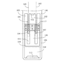
図1に本発明の環状の発電コイル(104)の内部で柱形磁石(107)とカップリングし、外部で外側導磁体(108)とカップリングする実施例の構造模式図を示す。
図2に図1の断面図を示す。
図1、図2の主な構成は下記の通りである。
FIG. 1 shows a structural schematic diagram of an embodiment in which an annular power generation coil (104) of the present invention is coupled with a columnar magnet (107) and is externally coupled with an outer magnetic conductor (108).
FIG. 2 shows a cross-sectional view of FIG.
The main configuration of FIGS. 1 and 2 is as follows.
ハウジング(100):弱導磁性および弱導電性材料により構成され、中空の円筒形を呈し、かつ内部の一端は内部に向かって一つの環状巻線コネクタ(101)を延伸し、その末端は延伸して環状の発電コイル(104)と連結し、その環状巻線コネクタ(101)とハウジング(100)の内孔との間に環状空間(103)を備え、環状巻線コネクタ(101)の中心に円孔状空間(102)を備え、環状の発電コイル(104)に出力導線(105)を設けることにより、環状の発電コイル(104)の発電電気エネルギーを外部に出力する。 Housing (100): Constructed of weakly magnetic and weakly conductive material, has a hollow cylindrical shape, and one end of the inside extends one annular winding connector (101) toward the inside, the end of which extends The annular power generation coil (104) is connected, and an annular space (103) is provided between the annular winding connector (101) and the inner hole of the housing (100). Is provided with a circular hole space (102), and the output power (105) is provided in the annular power generation coil (104), so that the generated electrical energy of the annular power generation coil (104) is output to the outside.
モーションブロックアセンブリ(106):弱導磁性および弱導電性材料により構成され、モーションブロックのカップ構造(110)を備え、外側導磁体(108)と結合し、モーションブロックのカップ構造(110)の中にモーションブロックの中柱(109)と結合する柱形磁石(107)を設け、かつモーションブロックの中柱(109)の周りはモーションブロックのカップ構造(110)とモーションブロック内部の環状空間(111)を形成することにより、環状の発電コイル(104)と環状巻線コネクタ(101)を相対的に軸方向に変位させ、かつ環状巻線コネクタ(101)の円孔状空間(102)と柱形磁石(107)、モーションブロックの中柱(109)を相対的に軸方向に変位させる。 Motion block assembly (106): composed of weakly conductive and weakly conductive material, comprising a motion block cup structure (110), coupled to an outer magnetic body (108), and in the motion block cup structure (110) Is provided with a columnar magnet (107) coupled to the middle pillar (109) of the motion block, and around the middle pillar (109) of the motion block is a cup structure (110) of the motion block and an annular space (111) inside the motion block. ), The annular power generation coil (104) and the annular winding connector (101) are relatively displaced in the axial direction, and the annular space (102) and the column of the annular winding connector (101) are formed. The shape magnet (107) and the middle pillar (109) of the motion block are relatively displaced in the axial direction.
環状巻線コネクタ(101)の円孔状空間(102)とハウジング(100)内壁との間に第一バッファー体(112)を設置し、モーションブロックアセンブリ(106)の中心柱体(109)と柱形磁石(107)と外側導磁体(108)が軸方向に変位するとき、緩衝する。 A first buffer body (112) is installed between the circular space (102) of the annular winding connector (101) and the inner wall of the housing (100), and the central column body (109) of the motion block assembly (106) When the columnar magnet (107) and the outer conductor (108) are displaced in the axial direction, they are buffered.
上述した柱形磁石(107)は外側導磁体(108)が軸方向に往復振動し、環状の発電コイル(104)を通過するとき、環状の発電コイル(104)が発電効果を発揮する。 In the columnar magnet (107) described above, when the outer magnetic conductor (108) reciprocally vibrates in the axial direction and passes through the annular power generation coil (104), the annular power generation coil (104) exhibits a power generation effect.
ハウジング(100)のハウジング内部の円筒空間(114)とモーションブロックアセンブリ(106)の周辺を相対的に軸方向に変位させ、かつモーションブロックアセンブリ(106)とハウジング(100)の内部にある円筒空間(114)に内壁との間に第二バッファー体(113)を設置し、モーションブロックアセンブリ(106)が軸方向に変位するとき、緩衝する。 The cylindrical space (114) inside the housing of the housing (100) and the periphery of the motion block assembly (106) are relatively axially displaced, and the cylindrical space is inside the motion block assembly (106) and the housing (100). A second buffer body (113) is installed between the inner wall and the inner wall at (114), and cushions when the motion block assembly (106) is displaced in the axial direction.
(第2実施形態)
図3に本発明の環状の発電コイル(104)内部で柱形磁石(107)とカップリングし、外部で柱形磁石(107)と相対的に同じ極性である外側磁石(117)とカップリングする実施例の構造模式図を示す。
図3の断面図は図2と同じである。
図3の主な構成は下記の通りである。
(Second Embodiment)
FIG. 3 shows a coupling with the columnar magnet (107) inside the annular power generation coil (104) of the present invention and a coupling with the outer magnet (117) having the same polarity as the columnar magnet (107) on the outside. The structural schematic diagram of the Example which does is shown.
The sectional view of FIG. 3 is the same as FIG.
The main configuration of FIG. 3 is as follows.
ハウジング(100):弱導磁性および弱導電性材料により構成され、中空の円筒形を呈し、かつ内部の一端は内部に向かって一つの環状巻線コネクタ(101)を延伸し、その末端は延伸して環状の発電コイル(104)と連結し、その環状巻線コネクタ(101)とハウジング(100)の内孔との間に環状空間(103)を備え、環状巻線コネクタ(101)の中心に円孔状空間(102)を備え、環状の発電コイル(104)に出力導線(105)を設けることにより、環状の発電コイル(104)の発電電気エネルギーを外部に出力する。 Housing (100): Constructed of weakly magnetic and weakly conductive material, has a hollow cylindrical shape, and one end of the inside extends one annular winding connector (101) toward the inside, the end of which extends The annular power generation coil (104) is connected, and an annular space (103) is provided between the annular winding connector (101) and the inner hole of the housing (100). Is provided with a circular hole space (102), and the output power (105) is provided in the annular power generation coil (104), so that the generated electrical energy of the annular power generation coil (104) is output to the outside.
モーションブロックアセンブリ(106):弱導磁性および弱導電性材料により構成され、モーションブロックのカップ構造(110)を備え、外側磁石(117)と結合し、モーションブロックのカップ構造(110)の中にモーションブロックの中柱(109)と結合する柱形磁石(107)を設け、かつモーションブロックの中柱(109)の周りはモーションブロックのカップ構造(110)とモーションブロック内部の環状空間(111)を形成することにより、環状の発電コイル(104)と環状巻線コネクタ(101)を相対的に軸方向に変位させ、かつ環状巻線コネクタ(101)の円孔状空間(102)と柱形磁石(107)とモーションブロックの中柱(109)を相対的に軸方向に変位させる。 Motion block assembly (106): composed of weakly conductive and weakly conductive material, with motion block cup structure (110), coupled to outer magnet (117), into motion block cup structure (110) A columnar magnet (107) connected to the middle column (109) of the motion block is provided, and the motion block cup structure (110) and the annular space (111) inside the motion block are arranged around the middle column (109) of the motion block. The annular power generation coil (104) and the annular winding connector (101) are relatively displaced in the axial direction, and the annular space (102) and the columnar shape of the annular winding connector (101) are formed. The magnet (107) and the middle pillar (109) of the motion block are relatively displaced in the axial direction.
環状巻線コネクタ(101)の円孔状空間(102)とハウジング(100)内壁との間に第一バッファー体(112)を設置し、モーションブロックの中柱(109)と柱形磁石(107)と外側導磁体(108)が軸方向に変位するとき、緩衝する。 The first buffer body (112) is installed between the circular hole space (102) of the annular winding connector (101) and the inner wall of the housing (100), and the middle column (109) of the motion block and the columnar magnet (107). ) And the outer magnetic body (108) are buffered when displaced in the axial direction.
上述した柱形磁石(107)は外側磁石(117)が軸方向に往復振動し、環状の発電コイル(104)を通過するとき、環状の発電コイル(104)が発電効果を発揮する。 In the columnar magnet (107) described above, when the outer magnet (117) reciprocally vibrates in the axial direction and passes through the annular power generation coil (104), the annular power generation coil (104) exhibits a power generation effect.
ハウジング(100)のハウジング内部の円筒空間(114)とモーションブロックアセンブリ(106)の周辺を相対的に軸方向に変位させ、かつモーションブロックアセンブリ(106)とハウジング(100)の内部にある円筒空間(114)に内壁との間に第二バッファー体(113)を設置し、モーションブロックアセンブリ(106)が軸方向に変位するとき、緩衝する。
柱形磁石(107)と柱形磁石(207)は、環状の発電コイル(104)の磁極面に相対して同極性であることを含む。または図4に示す通りである。
The cylindrical space (114) inside the housing of the housing (100) and the periphery of the motion block assembly (106) are relatively axially displaced, and the cylindrical space is inside the motion block assembly (106) and the housing (100). A second buffer body (113) is installed between the inner wall and the inner wall at (114), and cushions when the motion block assembly (106) is displaced in the axial direction.
It is included that the columnar magnet (107) and the columnar magnet (207) have the same polarity relative to the magnetic pole surface of the annular power generation coil (104). Or as shown in FIG.
柱形磁石(107)と柱形磁石(207)は、環状の発電コイル(104)の磁極面と相対的に異なる極性であることを含む。図4に本発明の環状の発電コイル(104)の内部で柱形磁石(107)とカップリングし、外部で柱形磁石(107)と相対的に異なる極性である外側磁石(117)とカップリングする実施例の構造模式図を示す。図4の断面図は図2と同じである。 It is included that the columnar magnet (107) and the columnar magnet (207) have different polarities from the magnetic pole surface of the annular power generation coil (104). In FIG. 4, the outer magnet (117) and the cup which are coupled to the columnar magnet (107) inside the annular power generation coil (104) of the present invention and have a polarity relatively different from that of the columnar magnet (107) outside. The structural schematic diagram of the Example which rings is shown. The cross-sectional view of FIG. 4 is the same as FIG.
(第3実施形態)
図5に本発明は複数段の環状の発電コイル(104)、(204)により構成され、環状の発電コイル(104)、(204)の内部で柱形磁石(107)、(207)とカップリングし、外部で外側導磁体(108)、(208)とカップリングする実施例の構造模式図を示す。
図5の断面図は図2と同じである。
図5の主な構成は下記の通りである。
(Third embodiment)
In FIG. 5, the present invention is composed of a plurality of annular power generation coils (104) and (204). Columnar magnets (107) and (207) and cups are formed inside the annular power generation coils (104) and (204). The structural schematic diagram of the Example which rings and couple | bonds with an outer side magnetic body (108) and (208) outside is shown.
The cross-sectional view of FIG. 5 is the same as FIG.
The main configuration of FIG. 5 is as follows.
ハウジング(100):弱導磁性および弱導電性材料により構成され、中空の円筒形を呈し、かつ内部の一端は内部に向かって一つの環状巻線コネクタ(101)を延伸し、その末端は延伸して環状の発電コイル(104)と結合し、更に環状巻線コネクタ(201)と結合し、また延伸して環状の発電コイル(204)と結合し、その環状巻線コネクタ(101)とハウジング(100)の内孔との間に環状空間(103)を備え、環状の発電コイル(104)、(204)を同極になるように並列接続し、または直列接続することにより発電電圧を加え、出力導線(105)を設けることにより、環状の発電コイル(104)、(204)の発電電気エネルギーを外部に出力する。 Housing (100): Constructed of weakly magnetic and weakly conductive material, has a hollow cylindrical shape, and one end of the inside extends one annular winding connector (101) toward the inside, the end of which extends Then, it couple | bonds with the cyclic | annular generator coil (104), and also couple | bonds with the cyclic | annular winding connector (201), and also extends | stretches and couple | bonds with the cyclic | annular generator coil (204), the cyclic | annular winding connector (101) and housing An annular space (103) is provided between the inner hole of (100), and the annular power generating coils (104) and (204) are connected in parallel so as to have the same polarity, or the generated voltage is applied by connecting them in series. By providing the output lead wire (105), the generated electric energy of the annular power generation coils (104), (204) is output to the outside.
モーションブロックアセンブリ(206):弱導磁性および弱導電性材料により構成され、モーションブロックのカップ構造(110)を備え、外側導磁体(108)と結合し、またカップ構造の分割リング(210)と再結合し、更に延伸して外側導磁体(208)と結合し、モーションブロックのカップ構造(110)の中にモーションブロックの中柱(109)と結合する柱形磁石(107)を設け、かつモーションブロックの中柱(209)と結合し、更に延伸して柱形磁石(207)と結合し、かつモーションブロックの中柱(109)の周りはモーションブロックのカップ構造(110)とモーションブロック内部の環状空間(111)を形成することにより、環状の発電コイル(104)、(204)と環状巻線コネクタ(201)と環状巻線コネクタ(101)を相対的に軸方向に変位させ、かつ環状巻線コネクタ(101)と環状巻線コネクタ(201)の円孔状空間(102)と柱形磁石(107)、(207)、モーションブロックの中柱(109)、(209)を相対的に軸方向に変位させる。 Motion block assembly (206): composed of weakly conductive and weakly conductive material, comprising a motion block cup structure (110), coupled to the outer conductor (108), and a cup structure split ring (210); Providing a columnar magnet (107) for recombination, further stretching and coupling with the outer conductor (208), coupling the motion block center column (109) in the motion block cup structure (110); and Combined with the middle block (209) of the motion block, and further extended to couple with the columnar magnet (207), and around the middle column (109) of the motion block, the cup structure (110) of the motion block and the inside of the motion block By forming the annular space (111), the annular power generation coils (104), (204) and the annular winding connector (2 1) and the annular winding connector (101) are relatively displaced in the axial direction, and the annular space (102) and the columnar magnet (107) of the annular winding connector (101) and the annular winding connector (201). ), (207), and the middle pillars (109), (209) of the motion block are relatively displaced in the axial direction.
環状巻線コネクタ(101)の円孔状空間(102)とハウジング(100)内壁との間に第一バッファー体(112)を設置し、モーションブロックの中柱(109)、(209)と柱形磁石(107)、(207)と外側導磁体(108)、(208)が軸方向に変位するとき、緩衝する。 The first buffer body (112) is installed between the circular hole space (102) of the annular winding connector (101) and the inner wall of the housing (100), and the middle pillars (109), (209) and pillars of the motion block are arranged. When the shape magnets (107) and (207) and the outer magnetic conductors (108) and (208) are displaced in the axial direction, they are buffered.
上述した柱形磁石(107)と柱形磁石(207)を通してモーションブロックの中柱(209)を隔てる間隔と環状の発電コイル(104)と環状の発電コイル(204)を通して環状巻線コネクタ(201)を隔てる間隔は、柱形磁石(107)と柱形磁石(207)と外側導磁体(108)と外側導磁体(208)が軸方向に往復振動し、環状の発電コイル(104)と環状の発電コイル(204)を通過するとき、環状の発電コイル(104)と環状の発電コイル(204)が同位相の電圧を作る。 The space between the columnar magnet (107) and the columnar magnet (207) separating the middle column (209) of the motion block, and the annular winding connector (201) through the annular generator coil (104) and the annular generator coil (204). ), The columnar magnet (107), the columnar magnet (207), the outer conductor (108), and the outer conductor (208) reciprocate in the axial direction so that the annular power generation coil (104) When passing through the power generating coil (204), the annular power generating coil (104) and the annular power generating coil (204) generate voltages having the same phase.
ハウジング(100)のハウジング内部の円筒空間(114)とモーションブロックアセンブリ(206)の周辺を相対的に軸方向に変位させ、かつモーションブロックアセンブリ(206)とハウジング(100)の内部にある円筒空間(114)に内壁との間に第二バッファー体(113)を設置し、モーションブロックアセンブリ(206)が軸方向に変位するとき、緩衝する。 The cylindrical space (114) inside the housing of the housing (100) and the periphery of the motion block assembly ( 2 06) are relatively displaced in the axial direction and are inside the motion block assembly ( 2 06) and the housing (100). install the second buffer body between the inner wall in a cylindrical space (114) to (113), a motion block assembly (2 06) is when displaced in the axial direction, to buffer.
(第4実施形態)
図6に本発明は複数段の環状の発電コイル(104)、(204)により構成され、環状の発電コイル(104)、(204)の内部で柱形磁石(107)、(207)とカップリングし、外部で複数段の柱形磁石(107)と相対的に同じ極性である外側磁石(117)、(217)とカップリングする実施例の構造模式図を示す。
図6の断面図と図2と同じである。
図6の主な構成は下記の通りである。
(Fourth embodiment)
In FIG. 6, the present invention is composed of a plurality of annular power generation coils (104) and (204). Columnar magnets (107) and (207) and cups are formed inside the annular power generation coils (104) and (204). The structural schematic diagram of the Example which carries out the ring and couples with the outer magnets (117) and (217) which are the same polarity relatively as the multistage columnar magnet (107) is shown.
6 is the same as the cross-sectional view of FIG. 6 and FIG.
The main configuration of FIG. 6 is as follows.
ハウジング(100):弱導磁性および弱導電性材料により構成され、中空の円筒形を呈し、かつ内部の一端は内部に向かって一つの環状巻線コネクタ(101)を延伸し、その末端は延伸して環状の発電コイル(104)と結合し、更に環状巻線コネクタ(201)と結合し、また延伸して環状の発電コイル(204)と結合し、その環状巻線コネクタ(101)とハウジング(100)の内孔との間に環状空間(103)を備え、環状巻線コネクタ(101)の中心に円孔状空間(102)を備え、環状の発電コイル(104)、(204)を同極になるように並列接続し、または直列接続することにより発電電圧を加え、出力導線(105)を設けることにより、環状の発電コイル(104)、(204)の発電電気エネルギーを外部に出力する。 Housing (100): Constructed of weakly magnetic and weakly conductive material, has a hollow cylindrical shape, and one end of the inside extends one annular winding connector (101) toward the inside, the end of which extends Then, it couple | bonds with the cyclic | annular generator coil (104), and also couple | bonds with the cyclic | annular winding connector (201), and also extends | stretches and couple | bonds with the cyclic | annular generator coil (204), the cyclic | annular winding connector (101) and housing An annular space (103) is provided between the inner hole of (100), a circular hole space (102) is provided at the center of the annular winding connector (101), and annular power generation coils (104), (204) are provided. The generated electric energy is applied by connecting in parallel or in series so as to have the same polarity, and by providing the output lead wire (105), the generated electric energy of the annular power generation coils (104) and (204) is externally supplied. To output.
モーションブロックアセンブリ(206):弱導磁性および弱導電性材料により構成され、モーションブロックのカップ構造(110)を備え、外側磁石(117)と結合し、またカップ構造の分割リング(210)と再結合し、更に延伸して外側磁石(217)と結合し、モーションブロックのカップ構造(110)の中にモーションブロックの中柱(109)と結合する柱形磁石(107)を設け、かつモーションブロックの中柱(209)と結合し、更に延伸して柱形磁石(207)と結合し、かつモーションブロックの中柱(109)の周りはモーションブロックのカップ構造(110)とモーションブロック内部の環状空間(111)を形成することにより、環状の発電コイル(104)、(204)と環状巻線コネクタ(201)と環状巻線コネクタ(101)を相対的に軸方向に変位させ、かつ環状巻線コネクタ(101)と環状巻線コネクタ(201)の円孔状空間(102)と柱形磁石(107)、(207)、モーションブロックの中柱(109)、(209)を相対的に軸方向に変位させる。 Motion block assembly (206): composed of weakly conductive and weakly conductive material, comprising motion block cup structure (110), coupled to outer magnet (117), and recombined with cup structure split ring (210). A columnar magnet (107) that couples with the outer column (217), couples with the outer magnet (217), couples with the middle column (109) of the motion block in the motion block cup structure (110), and the motion block It is connected to the center pillar (209) of the motion block, and is further extended to be connected to the columnar magnet (207), and the motion block cup structure (110) and the annular shape inside the motion block are arranged around the center pillar (109) of the motion block. By forming the space (111), the annular power generation coils (104), (204) and the annular winding connector (201 And the annular winding connector (101) are relatively axially displaced, and the annular space (102) and the columnar magnet (107) of the annular winding connector (101) and the annular winding connector (201), (207) The middle pillars (109) and (209) of the motion block are relatively displaced in the axial direction.
環状巻線コネクタ(101)の円孔状空間(102)とハウジング(100)内壁との間に第一バッファー体(112)を設置し、モーションブロックの中柱(109)、(209)と柱形磁石(107)、(207)と外側磁石(117)、(217)が軸方向に変位するとき、緩衝する。 The first buffer body (112) is installed between the circular hole space (102) of the annular winding connector (101) and the inner wall of the housing (100), and the middle pillars (109), (209) and pillars of the motion block are arranged. When the shape magnets (107) and (207) and the outer magnets (117) and (217) are displaced in the axial direction, they are buffered.
上述した柱形磁石(107)と柱形磁石(207)と外側磁石(117)と外側磁石(217)を通してモーションブロックの中柱(209)を隔てる間隔と環状の発電コイル(104)と環状の発電コイル(204)を通して環状巻線コネクタ(201)を隔てる間隔は、柱形磁石(107)と柱形磁石(207)と外側磁石(117)と外側磁石(217)が軸方向に往復振動し、環状の発電コイル(104)と環状の発電コイル(204)を通過するとき、環状の発電コイル(104)と環状の発電コイル(204)が同位相の電圧を作る。 The interval between the columnar magnet (107), the columnar magnet (207), the outer magnet (117) and the outer magnet (217) separating the middle column (209) of the motion block, the annular power generation coil (104) and the annular magnet The space separating the annular winding connector (201) through the generator coil (204) is such that the columnar magnet (107), the columnar magnet (207), the outer magnet (117), and the outer magnet (217) reciprocate in the axial direction. When passing through the annular power generating coil (104) and the annular power generating coil (204), the annular power generating coil (104) and the annular power generating coil (204) generate voltages having the same phase.
ハウジング(100)のハウジング内部の円筒空間(114)とモーションブロックアセンブリ(206)の周辺を相対的に軸方向に変位させ、かつモーションブロックアセンブリ(206)とハウジング(100)の内部にある円筒空間(114)に内壁との間に第二バッファー体(113)を設置し、モーションブロックアセンブリ(206)が軸方向に変位するとき、緩衝する。
The cylindrical space (114) inside the housing of the housing (100) and the periphery of the motion block assembly ( 2 06) are relatively displaced in the axial direction and are inside the motion block assembly ( 2 06) and the housing (100). install the second buffer body between the inner wall in a cylindrical space (114) to (113), a motion block assembly (2 06) is when displaced in the axial direction, to buffer.
柱形磁石(107)と柱形磁石(207)の二者は、環状の発電コイル(104)の磁極面に相対して、外側磁石(117)と外側磁石(217)に相対的に環状の発電コイル(204)の磁極面に相対して同極性であることを含む。または図7に示す通りである。 The two of the columnar magnet (107) and the columnar magnet (207) are relatively annular to the outer magnet (117) and the outer magnet (217) relative to the magnetic pole surface of the annular power generation coil (104). Including the same polarity relative to the magnetic pole surface of the power generation coil (204). Or as shown in FIG.
柱形磁石(107)と柱形磁石(207)は、環状の発電コイル(104)の磁極面に相対して、及び外側磁石(117)と外側磁石(217)が環状の発電コイル(204)の磁極面に相対して異なる極性であることを含む。図7に本発明は複数段の環状の発電コイル(104)、(204)により構成され、環状の発電コイル(104)、(204)の内部で柱形磁石(107)、(207)とカップリングし、外部で複数段の柱形磁石(107)に相対して異なる極性の外側磁石(117)、(217)とカップリングする実施例の構造模式図を示す。図7の断面図と図2と同じである。 The columnar magnet (107) and the columnar magnet (207) are opposed to the magnetic pole surface of the annular power generation coil (104), and the outer magnet (117) and the outer magnet (217) are annular in the power generation coil (204). Including different polarities relative to the magnetic pole face. In FIG. 7, the present invention includes a plurality of stages of annular power generation coils (104) and (204), and columnar magnets (107) and (207) and cups inside the annular power generation coils (104) and (204). The structural schematic diagram of the Example which carries out a ring and couples with the outer magnets (117) and (217) of a different polarity relative to the multi-stage columnar magnet (107) outside is shown. 7 is the same as the cross-sectional view of FIG. 7 and FIG.
前述した図5の実施例に設置される柱形磁石(107)、柱形磁石(207)、環状の発電コイル(104)、環状の発電コイル(204)、外側導磁体(108)、外側導磁体(208)は、全て2個以上により構成される。 The columnar magnet (107), the columnar magnet (207), the annular power generation coil (104), the annular power generation coil (204), the outer magnetic conductor (108), the outer conductor, which are installed in the embodiment of FIG. The magnetic bodies (208) are all composed of two or more.
前述した図6、7の実施例に設置される柱形磁石(107)、柱形磁石(207)、環状の発電コイル(104)、環状の発電コイル(204)、外側磁石(117)、外側磁石(217)は、全て2個以上により構成される。 The columnar magnet (107), the columnar magnet (207), the annular power generation coil (104), the annular power generation coil (204), the outer magnet (117), and the outside installed in the embodiment of FIGS. The magnets (217) are all composed of two or more.
前述した図5の実施例に設置される柱形磁石(107)、柱形磁石(207)、外側導磁体(108)、外側導磁体(208)、全て2個以上により構成され、かつ環状の発電コイル(104)は1個により構成される。 Each of the columnar magnet (107), the columnar magnet (207), the outer magnetic conductor (108), and the outer magnetic conductor (208) installed in the embodiment of FIG. The power generation coil (104) is composed of one piece.
前述した図6、7の実施例に設置される柱形磁石(107)、柱形磁石(207)、外側磁石(117)、外側磁石(217)は、全て2個以上により構成され、かつ環状の発電コイル(104)は1個により構成される。 The columnar magnet (107), the columnar magnet (207), the outer magnet (117), and the outer magnet (217) installed in the embodiment of FIGS. The power generating coil (104) is composed of one piece.
(100):ハウジング
(101):環状巻線コネクタ
(102):円孔状空間
(103):環状空間
(104)、(204):環状の発電コイル
(105):出力導線
(106)、(206):モーションブロックアセンブリ
(107)、(207):柱形磁石
(108)、(208):外側導磁体
(109)、(209):モーションブロックの中柱
(110):モーションブロックのカップ構造
(111):モーションブロック内部の環状空間
(112):第一バッファー体
(113):第二バッファー体
(114):ハウジング内部の円筒空間
(117)、(217):外側磁石
(201):環状巻線コネクタ
(210):カップ構造の分割リング
(100): Housing (101): Annular winding connector (102): Circular space (103): Annular space (104), (204): An annular power generation coil (105): Output conductor (106), ( 206): Motion block assembly (107), (207): Columnar magnet (108), (208): Outer magnetic conductor (109), (209): Middle column of motion block (110): Cup structure of motion block (111): annular space inside motion block (112): first buffer body (113): second buffer body (114): cylindrical space (117) inside housing (217): outer magnet (201): annular Winding connector (210): Split ring with cup structure
Claims (12)
円柱状であり軸方向において異なる磁極を有する柱形磁石(107)、および、柱形磁石(107)の外部で柱形磁石(107)を覆う外側導磁体(108)が設置されており、柱形磁石(107)および外側導磁体(108)が、モーションブロックアセンブリ(106)を形成し、相対設置されていることで磁気回路を形成し、同期に軸方向に移動可能であり、柱形磁石(107)の外径が外側導磁体(108)の内径より小さく形成されており、柱形磁石(107)と外側導磁体(108)との間に環状の隙間が形成されており環状の発電コイル(104)が通過し、環状の発電コイル(104)が軸方向における往復振動を行うとき、レンツの法則の効果により、環状の発電コイル(104)が電気エネルギーを発生し、
ハウジング(100)は、弱導磁性および弱導電性材料により構成され、中空の円筒形を呈し、かつ内部の一端は内部に向かって一つの環状巻線コネクタ(101)を延伸し、その末端は延伸して環状の発電コイル(104)と連結し、その環状巻線コネクタ(101)とハウジング(100)の内孔との間に環状空間(103)を備え、環状巻線コネクタ(101)の中心に円孔状空間(102)を備え、環状の発電コイル(104)に出力導線(105)を設けることにより、環状の発電コイル(104)の発電電気エネルギーを外部に出力し、
モーションブロックアセンブリ(106)は、弱導磁性および弱導電性材料により構成され、カップ構造(110)により構成されており、外側導磁体(108)と結合し、カップ構造(110)の中に中柱(109)と結合する柱形磁石(107)を設け、かつモーションブロックの中柱(109)の周りはモーションブロックのカップ構造(110)と内部の環状空間(111)を形成することにより、環状の発電コイル(104)と環状巻線コネクタ(101)が結合し、モーションブロックとコイルを相対的に軸方向に変位させ、かつ環状巻線コネクタ(101)の円孔状空間(102)と柱形磁石(107)、モーションブロックの中柱(109)を相対的に軸方向に変位させ、
環状巻線コネクタ(101)の円孔状空間(102)とハウジング(100)内壁との間に第一バッファー体(112)を設置し、モーションブロックアセンブリ(106)の中心柱体(109)と柱形磁石(107)と外側導磁体(108)が軸方向に変位するとき、緩衝し、
上述したモーションブロックが軸方向において往復振動し、柱形磁石(107)と外側導磁体(108)が環状の発電コイル(104)を通過するとき、環状の発電コイル(104)が電気エネルギーを発生しし、
ハウジング(100)の内部の円筒空間(114)はモーションブロックアセンブリ(106)の周辺を収容し相対的に軸方向に変位し、かつモーションブロックアセンブリ(106)とハウジング(100)の内部にある円筒空間(114)に内壁との間に第二バッファー体(113)を設置し、モーションブロックアセンブリ(106)が軸方向に変位するとき、緩衝することを特徴とする往復振動式発電装置。 A reciprocating vibration power generation apparatus including a magnetic motion block, the magnetic motion block having an inner post and an outer ring portion,
Columnar magnet having different magnetic poles in and axially cylindrical (107), and the outer magnetic conductive member (108) covering the columnar magnet (107) outside the columnar magnet (107) has been installed, the pillars shape magnet (107) and an outer magnetic conductive member (108) forms a motion block assembly (106) to form a magnetic circuit by being relative installation, being movable synchronously in the axial direction, the columnar magnet The outer diameter of (107) is smaller than the inner diameter of the outer magnet (108), and an annular gap is formed between the columnar magnet (107) and the outer magnet (108). When the coil (104) passes and the annular power generation coil (104) reciprocates in the axial direction, due to the effect of Lenz's law, the annular power generation coil (104) generates electrical energy,
The housing (100) is made of weakly conductive and weakly conductive material, has a hollow cylindrical shape, and one end of the inside extends one annular winding connector (101) toward the inside, and its end is The ring-shaped power generation coil (104) is extended and connected, and an annular space (103) is provided between the ring-winding connector (101) and the inner hole of the housing (100). By providing a circular hole-shaped space (102) in the center and providing an output lead wire (105) to the annular power generation coil (104), the generated electrical energy of the annular power generation coil (104) is output to the outside,
Motion block assembly (106) is constituted by having poor magnetic and weakly conductive material, is constituted by mosquito-up structure (110), and coupled with the outside magnetic conductive member (108), mosquito-up structure (110) the cup-shaped structure (110) and the inner portion of the annular space (111) around the motion block of the columnar magnet which binds with center post (109) (107) is provided, and center column of motion block (109) in the By forming, the annular power generation coil (104) and the annular winding connector (101) are coupled, the motion block and the coil are relatively displaced in the axial direction, and the annular winding connector (101) has a circular hole shape. Displace the space (102), the columnar magnet (107), and the middle column (109) of the motion block in the axial direction,
A first buffer body (112) is installed between the circular space (102) of the annular winding connector (101) and the inner wall of the housing (100), and the central column body (109) of the motion block assembly (106) When the columnar magnet (107) and the outer conductor (108) are displaced in the axial direction, they are buffered,
Above motion block is reciprocally vibrate in the axial direction, a columnar magnet (107) when the outer magnetic conductive member (108) passes through the ring-shaped generating coil (104), annular power generation coil (104) is an electric energy Occurs and
Cylindrical space of the inner portion of the housing (100) (114) is displaced axially relative to housing the peripheral motion block assembly (106), and there motion block assembly (106) within the housing (100) install the second buffer body (113) between the inner wall in a cylindrical space (114), when the motion block assembly (106) is displaced in the axial direction, round-trip vibratory power generator you wherein the buffering .
ハウジング(100)は、弱導磁性および弱導電性材料により構成され、中空の円筒形を呈し、かつ内部の一端は内部に向かって一つの環状巻線コネクタ(101)を延伸し、その末端は延伸して環状の発電コイル(104)と連結し、その環状巻線コネクタ(101)とハウジング(100)の内孔との間に環状空間(103)を備え、環状巻線コネクタ(101)の中心に円孔状空間(102)を備え、環状の発電コイル(104)に出力導線(105)を設けることにより、環状の発電コイル(104)の発電電気エネルギーを外部に出力し、
モーションブロックアセンブリ(106)は、弱導磁性および弱導電性材料により構成され、カップ構造(110)により構成され、外側磁石(117)と結合し、モーションブロックのカップ構造(110)の中間部に柱形磁石(107)と結合するモーションブロックの中柱(109)を有し、モーションブロックの中柱(109)の周りはモーションブロックのカップ構造(110)と内部の環状空間(111)を形成することにより、環状の発電コイル(104)および環状巻線コネクタ(101)と結合し、モーションブロックおよびコイルを相対的に軸方向に変位させ、かつ環状巻線コネクタ(101)の円孔状空間(102)は柱形磁石(107)およびモーションブロックの中柱(109)と結合し、モーションブロックおよびコイルを相対的に軸方向に変位させ、
環状巻線コネクタ(101)の円孔状空間(102)とハウジング(100)内壁との間に第一バッファー体(112)を設置し、モーションブロックの中柱(109)と柱形磁石(107)と外側磁石(117)が軸方向に変位するとき、緩衝し、
モーションブロックが軸方向に往復移動し、柱形磁石(107)および外側磁石(117)が環状の発電コイル(104)を通過するとき、環状の発電コイル(104)が発電し、
ハウジング(100)の内部の円筒空間(114)はモーションブロックアセンブリ(106)の周辺を収容し相対的に軸方向に変位し、モーションブロックアセンブリ(106)とハウジング(100)の内部にある円筒空間(114)に内壁との間に第二バッファー体(113)を設置し、モーションブロックアセンブリ(106)が軸方向に変位するとき、緩衝し、
柱形磁石(107)と外側磁石(117)は、環状の発電コイル(104)の磁極面に相対して同極性であることを含むことを特徴とする請求項1に記載の往復振動式発電装置。 An outer magnet (117) coupled to the columnar magnet (107) inside the annular power generation coil (104 ) and having the same polarity as the columnar magnet (107) outside the annular power generation coil (104 ); An outer magnet (117) is provided in place of the outer conductor (108) according to claim 1,
The housing (100) is made of weakly conductive and weakly conductive material, has a hollow cylindrical shape, and one end of the inside extends one annular winding connector (101) toward the inside, and its end is The ring-shaped power generation coil (104) is extended and connected, and an annular space (103) is provided between the ring-winding connector (101) and the inner hole of the housing (100). By providing a circular hole-shaped space (102) in the center and providing an output lead wire (105) to the annular power generation coil (104), the generated electrical energy of the annular power generation coil (104) is output to the outside,
Motion block assembly (106) is constituted by having poor magnetic and weakly conductive material, is constituted by mosquito-up structure (110), coupled with the outer magnet (117), in a cup-shaped structure of motion block (110) It has a center column (109) of the motion block that bind to the columnar magnet (107) between portions, an annular inner portion around the cup-shaped structure of motion block (110) of the B-pillar (109) of the motor Activation block By forming the space (111), the annular power generation coil (104) and the annular winding connector (101) are coupled, the motion block and the coil are relatively displaced in the axial direction, and the annular winding connector (101 circular hole-shaped space) (102) binds the B-pillar (109) of the columnar magnet (107) and a motion block, the motion block Contact Displaces the fine coil relative axial,
The first buffer body (112) is installed between the circular hole space (102) of the annular winding connector (101) and the inner wall of the housing (100), and the middle column (109) of the motion block and the columnar magnet (107). ) And the outer magnet (117) are displaced when axially displaced,
Motion block is reciprocated in the axial direction, when the columnar magnet (107) and the outer magnet (117) passes through the ring-shaped generating coil (104), annular power generation coil (104) is power generation,
Within the housing internal cylinder space (100) (114) is displaced axially relative accommodate peripheral motion block assembly (106), mode Activation block assembly (106) and housing (100) A second buffer body (113) is installed between the inner wall and a cylindrical space (114). When the motion block assembly (106) is displaced in the axial direction,
The reciprocating vibration power generation according to claim 1, characterized in that the columnar magnet (107) and the outer magnet (117) have the same polarity relative to the magnetic pole surface of the annular power generation coil (104). apparatus.
ハウジング(100)は、弱導磁性および弱導電性材料により構成され、中空の円筒形を呈し、かつ内部の一端は内部に向かって一つの環状巻線コネクタ(101)を延伸し、その末端は延伸して環状の発電コイル(104)と結合し、更に他の環状巻線コネクタ(201)と結合し、また延伸して他の環状の発電コイル(204)と結合し、その環状巻線コネクタ(101)とハウジング(100)の内孔との間に環状空間(103)を備え、環状の発電コイル(104)および他の環状の発電コイル(204)を並列接続し、または直列接続することにより発電電圧を加え、環状の発電コイル(104)および他の環状の発電コイル(204)毎に出力導線(105)が設けられており、環状の発電コイル(104)および他の環状の発電コイル(204)の発電電気エネルギーを外部に出力し、
モーションブロックアセンブリ(206)は、弱導磁性および弱導電性材料により構成され、カップ構造(110)により構成され、外側導磁体(108)、およびカップ構造の分割リング(210)と結合し、延伸して他の外側導磁体(208)と結合し、カップ構造(110)の中にモーションブロックの中柱(109)を有し、柱形磁石(107)、および、他のモーションブロックの中柱(209)と結合し、延伸して他の柱形磁石(207)と結合し、モーションブロックの中柱(109)の周りはモーションブロックのカップ構造(110)と内部の環状空間(111)を形成することにより、環状の発電コイル(104)および他の環状の発電コイル(204)と他の環状巻線コネクタ(201)および環状巻線コネクタ(101)とを収容し、相対的に軸方向に変位させ、かつ環状巻線コネクタ(101)と他の環状巻線コネクタ(201)の円孔状空間(102)と柱形磁石(107)および他の柱形磁石(207)、モーションブロックの中柱(109)および他のモーションブロックの中柱(209)を相対的に軸方向に変位させ、
環状巻線コネクタ(101)の円孔状空間(102)とハウジング(100)内壁との間に第一バッファー体(112)を設置し、モーションブロックの中柱(109)および他のモーションブロックの中柱(209)と柱形磁石(107)および他の柱形磁石(207)と外側導磁体(108)および他の外側導磁体(208)とが軸方向に変位するとき、緩衝し、
上述した柱形磁石(107)および他の柱形磁石(207)を通して他のモーションブロックの中柱(209)を隔てる間隔と環状の発電コイル(104)および他の環状の発電コイル(204)を通して他の環状巻線コネクタ(201)を隔てる間隔は、モーションブロックが軸方向に往復振動し、柱形磁石(107)および他の柱形磁石(207)と外側導磁体(108)および他の外側導磁体(208)が、環状の発電コイル(104)および他の環状の発電コイル(204)を通過するとき電気エネルギーを発生し、環状の発電コイル(104)および他の環状の発電コイル(204)が同位相の電圧を作り、
ハウジング内部の円筒空間(114)はモーションブロックアセンブリ(206)の周辺を収容し相対的に軸方向に変位させ、かつモーションブロックアセンブリ(206)とハウジング(100)の内部にある円筒空間(114)に内壁との間に第二バッファー体(113)を設置し、モーションブロックアセンブリ(206)が軸方向に変位するとき、緩衝することを特徴とする請求項1に記載の往復振動式発電装置。 Annular power generation coil (104), and is constituted by the power generation coil of the annular axially (104) other annular power generation coil are spaced apart from the (204), an annular generator coil (104) and other cyclic Are coupled to the columnar magnet (107) and the other columnar magnet (207) inside the power generation coil (204) of the other, and are coupled to the outer conductor (108) and the other outer conductor (208) on the outside. ,
The housing (100) is made of weakly conductive and weakly conductive material, has a hollow cylindrical shape, and one end of the inside extends one annular winding connector (101) toward the inside, and its end is It extends and couples with the annular power generation coil (104), and further couples with another annular winding connector (201), and it stretches and couples with the other annular generation coil (204), and the annular winding connector. An annular space (103) is provided between (101) and the inner hole of the housing (100), and the annular power generating coil (104) and the other annular power generating coil (204) are connected in parallel or in series. the generated voltage applied by the generator coil (104) of cyclic and other annular generating coil (204) output lead (105) is provided for each power generation coil (104) of cyclic and other cyclic calling Outputs generating electrical energy of the coil (204) to the outside,
The motion block assembly (206) is composed of a weakly conductive and weakly conductive material, is composed of a cup structure (110), is coupled to the outer conductor (108), and a split ring (210) of the cup structure, and stretched. To the other outer magnetic conductor (208), and has the middle pillar (109) of the motion block in the cup structure (110), the columnar magnet (107), and the middle pillar of the other motion block. (209) and extended to join with another columnar magnet (207), and around the middle column (109) of the motion block, there is a cup structure (110) of the motion block and an internal annular space (111). by forming annular generator coil (104) and other cyclic generator coil (204) and the other tubular annular coil (201) and an annular coil set (1 1) accommodates a relatively axial direction is displaced, and a circular hole-shaped space (102) and the columnar magnet of annular coil set (101) and the other tubular annular coil (201) (107) and Relatively axially displace the other columnar magnet (207), the middle column (109) of the motion block and the middle column (209) of the other motion block ;
A first buffer body (112) is installed between the circular space (102) of the annular winding connector (101) and the inner wall of the housing (100), and the middle pillar (109) of the motion block and other motion blocks when and columnar magnet center post (209) (107) and other columnar magnet (207) and the outer magnetic conductive member (108) and other outer magnetic conductive member (208) is displaced in the axial direction, and a buffer,
Through the above-described columnar magnet (107) and the other columnar magnet (207), the space separating the middle column (209) of the other motion block and through the annular generator coil (104) and the other annular generator coil (204). The space separating the other annular winding connectors (201) is such that the motion block reciprocally vibrates in the axial direction, and the columnar magnet (107) and the other columnar magnet (207) and the outer conductor (108) and the other outer side. magnetic conductive member (208) is to generate electrical energy when passing through the annular power generation coil (104) and other cyclic generator coil (204), generating coil (104) of cyclic and other annular power generation coil ( 204) creates a voltage in phase,
Cylinder space housing interior of the cylinder space (114) is located inside the motion block assembly (2 06) near to accommodated relative axial displacement of and the motion block assembly (2 06) and housing (100), ( The reciprocating vibration type according to claim 1, wherein the second buffer body (113) is installed between the inner wall and the inner wall of the motion block assembly ( 200 ), and the motion block assembly (206) is buffered when displaced in the axial direction. Power generation device.
ハウジング(100)は、弱導磁性および弱導電性材料により構成され、中空の円筒形を呈し、かつ内部の一端は内部に向かって一つの環状巻線コネクタ(101)を延伸し、その末端は延伸して環状の発電コイル(104)と結合し、更に他の環状巻線コネクタ(201)と結合し、また延伸して他の環状の発電コイル(204)と結合し、その環状巻線コネクタ(101)とハウジング(100)の内孔との間に環状空間(103)を備え、環状巻線コネクタ(101)の中心に円孔状空間(102)を備え、環状の発電コイル(104)および他の環状の発電コイル(204)を並列接続し、または直列接続することにより発電電圧を加え、環状の発電コイル(104)および他の環状の発電コイル(204)毎に出力導線(105)を設けることにより、環状の発電コイル(104)および他の環状の発電コイル(204)の発電電気エネルギーを外部に出力し、
モーションブロックアセンブリ(206)は、弱導磁性および弱導電性材料により構成され、カップ構造(110)により構成され、外側磁石(117)、およびカップ構造の分割リング(210)と結合し、延伸して他の外側磁石(217)と結合し、カップ構造(110)の中に中柱(109)を有し、柱形磁石(107)、および他のモーションブロックの中柱(209)と結合し、延伸して他の柱形磁石(207)と結合し、モーションブロックの中柱(109)の周りはモーションブロックのカップ構造(110)と内部の環状空間(111)を形成することにより、環状の発電コイル(104)および他の環状の発電コイル(204)と他の環状巻線コネクタ(201)および環状巻線コネクタ(101)とを収容し、相対的に軸方向に変位させ、環状巻線コネクタ(101)と他の環状巻線コネクタ(201)の円孔状空間(102)は柱形磁石(107)および他の柱形磁石(207)、モーションブロックの中柱(109)および他のモーションブロックの中柱(209)を収容し、相対的に軸方向に変位させ、
環状巻線コネクタ(101)の円孔状空間(102)とハウジング(100)内壁との間に第一バッファー体(112)を設置し、モーションブロックの中柱(109)および他のモーションブロックの中柱(209)と柱形磁石(107)および他の柱形磁石(207)と外側磁石(117)および他の外側磁石(217)とが軸方向に変位するとき、緩衝し、
柱形磁石(107)および他の柱形磁石(207)と外側磁石(117)および他の外側磁石(217)とが他のモーションブロックの中柱(209)により隔てる間隔と、環状の発電コイル(104)および他の環状の発電コイル(204)を通して他の環状巻線コネクタ(201)を隔てる間隔とは、モーションブロックが軸方向に往復振動中において、柱形磁石(107)および他の柱形磁石(207)と外側磁石(117)および他の外側磁石(217)が、環状の発電コイル(104)および他の環状の発電コイル(204)を通過するとき電気エネルギーを発生し、環状の発電コイル(104)および他の環状の発電コイル(204)が同位相の電圧を作り、
ハウジング内部の円筒空間(114)はモーションブロックアセンブリ(206)の周辺を収容し相対的に軸方向に変位させ、かつモーションブロックアセンブリ(206)とハウジング(100)の内部にある円筒空間(114)に内壁との間に第二バッファー体(113)を設置し、モーションブロックアセンブリ(206)が軸方向に変位するとき、緩衝し、
柱形磁石(107)と他の柱形磁石(207)の二者は、環状の発電コイル(104)の磁極面に相対して、外側磁石(117)と他の外側磁石(217)に相対的に他の環状の発電コイル(204)の磁極面に相対して同極性を有することを特徴とする請求項2に記載の往復振動式発電装置。 Annular power generation coil (104), and is constituted by the power generation coil of the annular axially (104) other annular power generation coil are spaced apart from the (204), an annular generator coil (104) and other cyclic Are coupled with the columnar magnet (107) and the other columnar magnet (207) inside the power generation coil (204) of the ring, and the column is formed outside the ring-shaped power generation coil (104) and the other ring-shaped power generation coil (204). Coupling with an outer magnet (117) and other outer magnets (217) having the same polarity as the shaped magnet (107);
The housing (100) is made of weakly conductive and weakly conductive material, has a hollow cylindrical shape, and one end of the inside extends one annular winding connector (101) toward the inside, and its end is It extends and couples with the annular power generation coil (104), and further couples with another annular winding connector (201), and it stretches and couples with the other annular generation coil (204), and the annular winding connector. (101) and the inner hole of the housing (100) are provided with an annular space (103), the annular winding connector (101) is provided with a circular hole-like space (102), and an annular power generation coil (104 ). And other annular power generation coils ( 204) are connected in parallel or in series to apply a generated voltage, and output conductors (105) are provided for each of the annular power generation coil (104 ) and the other annular power generation coils ( 204). ) To output the generated electric energy of the annular power generation coil (104) and the other annular power generation coil (204) to the outside,
The motion block assembly (206) is composed of weakly conductive and weakly conductive material, is composed of a cup structure (110), is coupled to the outer magnet (117), and the split ring (210) of the cup structure, and extends. Coupled to the other outer magnet (217), having a middle column (109) in the cup structure (110), coupled to the columnar magnet (107) and the middle column (209) of the other motion block. , Extending and joining with other columnar magnets (207), and surrounding the middle column (109) of the motion block to form an annular space (111) with the cup structure (110) of the motion block generator accommodating a coil (104) and the power generation coil of the other annular (204) and another tubular annular coil (201) and an annular coil set (101) of relatively Is displaced in direction of the other annular coil set (101) circular hole-shaped space (102) of the tubular annular coil (201) is columnar magnet (107) and other columnar magnet (207), the motion block Accommodates the middle pillar (109) and the middle pillar (209) of other motion blocks , and relatively displaces them axially,
A first buffer body (112) is installed between the circular space (102) of the annular winding connector (101) and the inner wall of the housing (100), and the middle pillar (109) of the motion block and other motion blocks when and columnar magnet center post (209) (107) and other columnar magnet (207) and the outer magnet (117) and other outer magnets (217) is displaced in the axial direction, and a buffer,
The interval between the columnar magnet (107) and the other columnar magnet (207) and the outer magnet (117) and the other outer magnet (217) separated by the middle column (209) of the other motion block, and the annular generator coil (104) and the interval separating the other tubular annular coil (201) through the generating coil of the other annular (204), in a reciprocal vibration motion block is axially columnar magnet (107) and other pillars When the shaped magnet (207) and the outer magnet (117) and the other outer magnet (217) pass through the annular power generating coil (104) and the other annular power generating coil (204), they generate electrical energy, The generator coil (104) and the other annular generator coil (204) produce in-phase voltage,
Cylinder space housing interior of the cylinder space (114) is located inside the motion block assembly (2 06) near to accommodated relative axial displacement of and the motion block assembly (2 06) and housing (100), ( between the inner wall 114) placed second buffer body (113), when the motion block assembly (2 06) is displaced in the axial direction, and a buffer,
The two of the columnar magnet (107) and the other columnar magnet (207) are opposed to the outer magnet (117) and the other outer magnet (217) relative to the magnetic pole surface of the annular power generation coil (104). The reciprocating vibration power generator according to claim 2, wherein the reciprocating vibration power generator has the same polarity relative to the magnetic pole surface of another annular power generating coil (204).
Applications Claiming Priority (2)
| Application Number | Priority Date | Filing Date | Title |
|---|---|---|---|
| US13/071,616 | 2011-03-25 | ||
| US13/071,616 US8546964B2 (en) | 2011-03-25 | 2011-03-25 | Reciprocal vibration type power generator equipped with a moving inner columnar magnetic block surrounded by at least one coil set, and a moving outer annular magnetic block that surrounds the at least one coil set |
Publications (3)
| Publication Number | Publication Date |
|---|---|
| JP2012205496A JP2012205496A (en) | 2012-10-22 |
| JP2012205496A5 JP2012205496A5 (en) | 2015-05-07 |
| JP5988637B2 true JP5988637B2 (en) | 2016-09-07 |
Family
ID=46025337
Family Applications (1)
| Application Number | Title | Priority Date | Filing Date |
|---|---|---|---|
| JP2012063490A Active JP5988637B2 (en) | 2011-03-25 | 2012-03-21 | Reciprocating vibration power generator |
Country Status (6)
| Country | Link |
|---|---|
| US (1) | US8546964B2 (en) |
| EP (1) | EP2503677B1 (en) |
| JP (1) | JP5988637B2 (en) |
| KR (2) | KR20120109404A (en) |
| CN (2) | CN102780377B (en) |
| TW (2) | TWI565196B (en) |
Cited By (1)
| Publication number | Priority date | Publication date | Assignee | Title |
|---|---|---|---|---|
| WO2021173384A1 (en) * | 2020-02-27 | 2021-09-02 | John Sabah Gewarges | Coil regeneration device and method of use |
Families Citing this family (8)
| Publication number | Priority date | Publication date | Assignee | Title |
|---|---|---|---|---|
| JP5926017B2 (en) * | 2010-09-29 | 2016-05-25 | 日亜化学工業株式会社 | Cylindrical bonded magnet |
| US8546964B2 (en) * | 2011-03-25 | 2013-10-01 | Tai-Her Yang | Reciprocal vibration type power generator equipped with a moving inner columnar magnetic block surrounded by at least one coil set, and a moving outer annular magnetic block that surrounds the at least one coil set |
| US8736086B2 (en) * | 2011-03-25 | 2014-05-27 | Tai-Her Yang | Reciprocal vibration type power generator equipped with inner columnar and outer annular magnetic members, a power storage device, a rectifying circuit, and a charging circuit |
| GB201406329D0 (en) * | 2014-04-08 | 2014-05-21 | Mccartney Peter | An electromagnetic generator |
| JP6426931B2 (en) * | 2014-07-24 | 2018-11-21 | 学校法人東海大学 | Generator |
| CN104400438B (en) * | 2014-10-23 | 2017-02-15 | 郑州金泰制罐有限公司 | Winding drum manufacturing machine |
| KR200490804Y1 (en) | 2018-05-11 | 2020-02-11 | 양대현 | Multiple Vibration Spring Generators Using Wave |
| US11716003B1 (en) * | 2022-03-08 | 2023-08-01 | The United States Of America, As Represented By The Secretary Of The Navy | Electromagnetic arrays |
Family Cites Families (33)
| Publication number | Priority date | Publication date | Assignee | Title |
|---|---|---|---|---|
| US4454426A (en) * | 1981-08-17 | 1984-06-12 | New Process Industries, Inc. | Linear electromagnetic machine |
| JPS58165657A (en) * | 1982-03-25 | 1983-09-30 | Matsushita Electric Ind Co Ltd | Linear motor with brush |
| JPS614456A (en) * | 1984-06-14 | 1986-01-10 | Mitsubishi Electric Corp | Actuator |
| JPH1132470A (en) * | 1997-07-10 | 1999-02-02 | Yamatake Honeywell Co Ltd | Job-site equipment |
| US6220719B1 (en) * | 1998-02-11 | 2001-04-24 | Applied Innovative Technologies, Inc. | Renewable energy flashlight |
| US6768230B2 (en) * | 2002-02-19 | 2004-07-27 | Rockwell Scientific Licensing, Llc | Multiple magnet transducer |
| US6812583B2 (en) * | 2002-02-19 | 2004-11-02 | Rockwell Scientific Licensing, Llc | Electrical generator with ferrofluid bearings |
| US6729744B2 (en) * | 2002-03-29 | 2004-05-04 | Pat Y. Mah | Faraday flashlight |
| US6936937B2 (en) * | 2002-06-14 | 2005-08-30 | Sunyen Co., Ltd. | Linear electric generator having an improved magnet and coil structure, and method of manufacture |
| EP1378986A1 (en) * | 2002-07-02 | 2004-01-07 | Nti Ag | Constant force actuator |
| US6741151B1 (en) * | 2002-11-27 | 2004-05-25 | Levram Medical Systems, Ltd. | Moving coil linear actuator |
| US7569952B1 (en) * | 2003-04-18 | 2009-08-04 | Ferro Solutions, Inc. | High efficiency, inductive vibration energy harvester |
| JP2005094832A (en) * | 2003-09-12 | 2005-04-07 | Sony Corp | Generator |
| US7205677B2 (en) * | 2005-05-19 | 2007-04-17 | Incelex, Llc | Automated motion provider for self powered cell phones |
| US7501834B2 (en) * | 2005-06-21 | 2009-03-10 | Custom Sensors & Technologies, Inc. | Voice coil actuator with embedded capacitive sensor for motion, position and/or acceleration detection |
| US7148583B1 (en) * | 2005-09-05 | 2006-12-12 | Jeng-Jye Shau | Electrical power generators |
| US7554224B2 (en) * | 2006-02-22 | 2009-06-30 | Perpetuum Ltd. | Electromechanical generator for converting mechanical vibrational energy into electrical energy |
| US7688036B2 (en) * | 2006-06-26 | 2010-03-30 | Battelle Energy Alliance, Llc | System and method for storing energy |
| US20080001484A1 (en) * | 2006-07-03 | 2008-01-03 | Chris Fuller | Linear Electromechanical Vibrator with Axially Movable Magnet |
| CA2659839C (en) * | 2006-08-14 | 2012-03-20 | Liangju Lu | Vibration power generation |
| JP5150155B2 (en) * | 2007-02-23 | 2013-02-20 | 株式会社東芝 | Linear actuators and devices using linear actuators |
| JP2008259264A (en) * | 2007-04-02 | 2008-10-23 | Toshiba Corp | Oscillation power generating set |
| GB2439411B (en) * | 2007-04-27 | 2008-07-23 | Perpetuum Ltd | An electromechanical generator for converting mechanical vibrational energy into electrical energy |
| US20080296984A1 (en) * | 2007-05-29 | 2008-12-04 | Sanyo Electric Co., Ltd. | Energy converter |
| US7675202B1 (en) * | 2007-07-18 | 2010-03-09 | Benjamin Huang | Isotropic ring magnet linear voice coil motor |
| JP2009112069A (en) * | 2007-10-26 | 2009-05-21 | Sanyo Electric Co Ltd | Electronic equipment |
| CN101510717A (en) * | 2008-02-13 | 2009-08-19 | 叶建国 | Electric machine means |
| CN201656734U (en) * | 2010-01-21 | 2010-11-24 | 浙江工业大学 | Encircling type vibration power generating device |
| CN201690339U (en) * | 2010-04-13 | 2010-12-29 | 北汽福田汽车股份有限公司 | Shock absorber |
| JP2012039824A (en) * | 2010-08-10 | 2012-02-23 | Brother Ind Ltd | Vibration generator |
| JP5418485B2 (en) * | 2010-12-08 | 2014-02-19 | スミダコーポレーション株式会社 | Vibration generator |
| US8736086B2 (en) * | 2011-03-25 | 2014-05-27 | Tai-Her Yang | Reciprocal vibration type power generator equipped with inner columnar and outer annular magnetic members, a power storage device, a rectifying circuit, and a charging circuit |
| US8546964B2 (en) * | 2011-03-25 | 2013-10-01 | Tai-Her Yang | Reciprocal vibration type power generator equipped with a moving inner columnar magnetic block surrounded by at least one coil set, and a moving outer annular magnetic block that surrounds the at least one coil set |
-
2011
- 2011-03-25 US US13/071,616 patent/US8546964B2/en active Active
-
2012
- 2012-03-21 TW TW101109584A patent/TWI565196B/en active
- 2012-03-21 JP JP2012063490A patent/JP5988637B2/en active Active
- 2012-03-21 TW TW101205042U patent/TWM453030U/en not_active IP Right Cessation
- 2012-03-23 CN CN201210079622.9A patent/CN102780377B/en active Active
- 2012-03-23 KR KR1020120030053A patent/KR20120109404A/en not_active Application Discontinuation
- 2012-03-23 CN CN201220113708.4U patent/CN202602509U/en not_active Expired - Lifetime
- 2012-03-26 EP EP12161331.9A patent/EP2503677B1/en active Active
-
2018
- 2018-10-30 KR KR1020180130750A patent/KR20180122571A/en not_active Application Discontinuation
Cited By (1)
| Publication number | Priority date | Publication date | Assignee | Title |
|---|---|---|---|---|
| WO2021173384A1 (en) * | 2020-02-27 | 2021-09-02 | John Sabah Gewarges | Coil regeneration device and method of use |
Also Published As
| Publication number | Publication date |
|---|---|
| US8546964B2 (en) | 2013-10-01 |
| TWI565196B (en) | 2017-01-01 |
| KR20120109404A (en) | 2012-10-08 |
| TWM453030U (en) | 2013-05-11 |
| EP2503677A3 (en) | 2013-09-11 |
| CN102780377B (en) | 2017-04-12 |
| EP2503677A2 (en) | 2012-09-26 |
| JP2012205496A (en) | 2012-10-22 |
| US20120242175A1 (en) | 2012-09-27 |
| KR20180122571A (en) | 2018-11-13 |
| CN102780377A (en) | 2012-11-14 |
| EP2503677B1 (en) | 2014-10-15 |
| TW201251278A (en) | 2012-12-16 |
| CN202602509U (en) | 2012-12-12 |
Similar Documents
| Publication | Publication Date | Title |
|---|---|---|
| JP5988637B2 (en) | Reciprocating vibration power generator | |
| JP5923352B2 (en) | Power storage device capable of vibration power generation | |
| JP2012205496A5 (en) | ||
| JP2012205497A5 (en) | ||
| JP2011166894A (en) | Oscillating generator | |
| KR20120083468A (en) | Electrostatic induction power generator | |
| JP2013055714A (en) | Vibration power generator | |
| CN105743234B (en) | Permanent magnetism rotational oscillation motor and electrical equipment | |
| JP5414762B2 (en) | Vibration power generation unit, vibration power generation device, and vibration power generator | |
| KR101094651B1 (en) | Sensory signal output apparatus | |
| US20050184842A1 (en) | Magnetic inertial force generator | |
| KR101513879B1 (en) | Actuator using magnetic lenz effect | |
| KR101660845B1 (en) | vibration power generator | |
| RU129739U1 (en) | DYNAMIC SPEAKER | |
| RU129735U1 (en) | DYNAMIC SPEAKER | |
| RU129734U1 (en) | DYNAMIC SPEAKER | |
| WO2017081621A1 (en) | Linear electric generator | |
| TW201526473A (en) | Reciprocating power generator | |
| RU2015132852A (en) | Brushless DC Motor with Ring Electrodes | |
| RU2009125300A (en) | MAGNETO-ELECTRIC MACHINE WITH SPECIAL ACTIVATOR | |
| JP2004289978A (en) | Linear actuator, pump device using the same and compressor device | |
| JP2009142138A (en) | Mechanism using magnetic attracting force |
Legal Events
| Date | Code | Title | Description |
|---|---|---|---|
| A521 | Request for written amendment filed |
Free format text: JAPANESE INTERMEDIATE CODE: A523 Effective date: 20150320 |
|
| A621 | Written request for application examination |
Free format text: JAPANESE INTERMEDIATE CODE: A621 Effective date: 20150320 |
|
| A977 | Report on retrieval |
Free format text: JAPANESE INTERMEDIATE CODE: A971007 Effective date: 20160224 |
|
| A131 | Notification of reasons for refusal |
Free format text: JAPANESE INTERMEDIATE CODE: A131 Effective date: 20160329 |
|
| A521 | Request for written amendment filed |
Free format text: JAPANESE INTERMEDIATE CODE: A523 Effective date: 20160628 |
|
| TRDD | Decision of grant or rejection written | ||
| A01 | Written decision to grant a patent or to grant a registration (utility model) |
Free format text: JAPANESE INTERMEDIATE CODE: A01 Effective date: 20160719 |
|
| A61 | First payment of annual fees (during grant procedure) |
Free format text: JAPANESE INTERMEDIATE CODE: A61 Effective date: 20160809 |
|
| R150 | Certificate of patent or registration of utility model |
Ref document number: 5988637 Country of ref document: JP Free format text: JAPANESE INTERMEDIATE CODE: R150 |
|
| R250 | Receipt of annual fees |
Free format text: JAPANESE INTERMEDIATE CODE: R250 |
|
| R250 | Receipt of annual fees |
Free format text: JAPANESE INTERMEDIATE CODE: R250 |
|
| R250 | Receipt of annual fees |
Free format text: JAPANESE INTERMEDIATE CODE: R250 |
|
| R250 | Receipt of annual fees |
Free format text: JAPANESE INTERMEDIATE CODE: R250 |
|
| R250 | Receipt of annual fees |
Free format text: JAPANESE INTERMEDIATE CODE: R250 |