JP2012205122A - Frequency error detection device - Google Patents
Frequency error detection device Download PDFInfo
- Publication number
- JP2012205122A JP2012205122A JP2011068479A JP2011068479A JP2012205122A JP 2012205122 A JP2012205122 A JP 2012205122A JP 2011068479 A JP2011068479 A JP 2011068479A JP 2011068479 A JP2011068479 A JP 2011068479A JP 2012205122 A JP2012205122 A JP 2012205122A
- Authority
- JP
- Japan
- Prior art keywords
- circuit
- frequency
- signal
- frequency conversion
- frequency error
- Prior art date
- Legal status (The legal status is an assumption and is not a legal conclusion. Google has not performed a legal analysis and makes no representation as to the accuracy of the status listed.)
- Withdrawn
Links
Images


Classifications
-
- H—ELECTRICITY
- H04—ELECTRIC COMMUNICATION TECHNIQUE
- H04L—TRANSMISSION OF DIGITAL INFORMATION, e.g. TELEGRAPHIC COMMUNICATION
- H04L27/00—Modulated-carrier systems
- H04L27/18—Phase-modulated carrier systems, i.e. using phase-shift keying
- H04L27/22—Demodulator circuits; Receiver circuits
- H04L27/227—Demodulator circuits; Receiver circuits using coherent demodulation
- H04L27/2275—Demodulator circuits; Receiver circuits using coherent demodulation wherein the carrier recovery circuit uses the received modulated signals
- H04L27/2278—Demodulator circuits; Receiver circuits using coherent demodulation wherein the carrier recovery circuit uses the received modulated signals using correlation techniques, e.g. for spread spectrum signals
Abstract
Description
本発明の実施形態は、無線通信の受信機における周波数誤差検出装置に関する。 Embodiments described herein relate generally to a frequency error detection apparatus in a wireless communication receiver.
放送及び通信分野においては、フレーム等の一定長のブロック単位でデータ伝送が行われる。受信機は、伝送データ中にフレーム単位で格納されているフレーム同期信号等の識別子を検出し、このフレーム同期によりフレーム単位での復調処理を行っている。 In the broadcasting and communication fields, data transmission is performed in units of fixed length blocks such as frames. The receiver detects an identifier such as a frame synchronization signal stored in frame units in the transmission data, and performs demodulation processing in frame units by this frame synchronization.
例えば、中国(中華人民共和国)地上デジタル放送規格のDTMB(Digital Terrestrial Multimedia Broadcast)においては、フレームは、フレームボディ(以下、FB)とフレームヘッダ(以下、FH)とによって構成されている。FBには、変調されたソースストリームデータとシステム情報とが組み合わさった3780個のシンボルが格納されている。また、FHには、フレームを識別するための既知信号として擬似ランダムノイズ系列(以下、PN系列)が格納されている。DTMBは、FHとして3通りのFH長さを有しており、この3つのFH長さに対応して第1〜第3の放送モードを有している。 For example, in DTMB (Digital Terrestrial Multimedia Broadcast) of China (People's Republic of China) terrestrial digital broadcasting standard, a frame is composed of a frame body (hereinafter referred to as FB) and a frame header (hereinafter referred to as FH). The FB stores 3780 symbols in which modulated source stream data and system information are combined. The FH stores a pseudo random noise sequence (hereinafter referred to as a PN sequence) as a known signal for identifying a frame. DTMB has three FH lengths as FH, and has first to third broadcast modes corresponding to these three FH lengths.
ところで、受信機の受信信号として、周波数領域に変換した受信信号を入力し、この周波数領域に変換した受信信号と周波数領域に挿入された既知信号との相関を取り基準値からの変化量を求めることによって、周波数誤差を検出する技術がある。 By the way, a reception signal converted into the frequency domain is input as a reception signal of the receiver, and a correlation between the reception signal converted into the frequency domain and a known signal inserted in the frequency domain is obtained to obtain a change amount from the reference value. Thus, there is a technique for detecting a frequency error.
一方、受信機の受信信号として、時間領域に変換した受信信号を入力し、時間領域に変換した受信信号を周波数変換すると共に時間領域に挿入された既知信号を周波数変換し、この周波数変換された既知信号が伝送路で受けた歪みの影響を推定し、その推定値に基づいて受信信号に対して周波数的な歪み(周波数誤差)の補正を行う技術がある。 On the other hand, the received signal converted into the time domain is input as the received signal of the receiver, the received signal converted into the time domain is frequency-converted, and the known signal inserted in the time domain is frequency-converted, and this frequency-converted There is a technique for estimating the influence of distortion of a known signal on a transmission path and correcting a frequency distortion (frequency error) for a received signal based on the estimated value.
しかしながら、DTMBにおいて、前述したように時間領域の受信信号を周波数変換により周波数領域の信号として周波数的な歪み(誤差)を検出する場合、時間領域の既知信号の長さに対応した周波数変換回路が必要になる。DTMBでは時間領域の既知信号(フレームヘッダ:FH)として3通り(シンボル長さ420, 595, 945)用意されており、FHを周波数変換して利用する場合、この3通りの既知信号に対する3つの周波数変換回路と、シンボル長さ3780のフレームボディ(FB)を周波数変換するための1つの周波数変換回路とを併せて少なくとも4種類の周波数変換回路が必要になり、回路規模が大きくなるという問題がある。
However, in DTMB, when a frequency distortion (error) is detected as a frequency domain signal by frequency conversion of a received signal in the time domain as described above, a frequency conversion circuit corresponding to the length of a known signal in the time domain is used. I need it. In DTMB, three types (
本発明が解決しようとする課題は、時間領域の受信信号を周波数変換により周波数領域の信号として周波数的な歪み(誤差)を検出する場合、周波数変換回路が小さくて済み、回路規模を少なくすることができる周波数誤差検出装置を提供することである。 The problem to be solved by the present invention is that when frequency distortion (error) is detected as a frequency domain signal by frequency conversion of a received signal in the time domain, the frequency conversion circuit can be small and the circuit scale can be reduced. It is an object of the present invention to provide a frequency error detection device capable of
本発明の実施形態の周波数誤差検出装置は、
周期的に変化する既知信号を挿入されている受信信号に対して既知信号を抽出する既知信号抽出回路と、
前記既知信号抽出回路で抽出した既知信号を固定区間の中に分散配置させる第1の分散配置回路と、
前記第1の分散配置回路の出力を周波数変換し周波数領域の信号に変換する第1の周波数変換回路と、
前記第1の周波数変換回路の出力である周波数領域の信号を遅延検波することにより隣接周波数成分間の位相変動量を算出する第1の遅延検波回路と、
前記周期的に変化する既知信号と同じ系列を発生させる系列発生回路と、
前記系列発生回路で発生させた既知信号を固定区間の中に分散配置させる第2の分散配置回路と、
前記第2の分散配置回路の出力を周波数変換し周波数領域の信号に変換する第2の周波数変換回路と、
前記第2の周波数変換回路の出力である周波数領域の信号を遅延検波することにより隣接周波数成分間の位相変動量を算出する第2の遅延検波回路と、
前記第1の遅延検波回路の出力と前記第2の遅延検波回路の出力との相関値を出力する相関演算回路と、
前記相関値のうち電力の大きいピークを1つ以上検出し,基準値からの差分を算出し周波数誤差として出力するピーク検出回路と、を備える。
The frequency error detection apparatus of the embodiment of the present invention is
A known signal extraction circuit for extracting a known signal with respect to a received signal into which a known signal that periodically changes is inserted;
A first distributed arrangement circuit that distributes and arranges the known signals extracted by the known signal extraction circuit in a fixed section;
A first frequency conversion circuit for frequency-converting the output of the first distributed arrangement circuit and converting it to a frequency domain signal;
A first delay detection circuit that calculates a phase fluctuation amount between adjacent frequency components by delay detection of a signal in a frequency domain that is an output of the first frequency conversion circuit;
A sequence generation circuit for generating the same sequence as the known signal that periodically changes;
A second distributed arrangement circuit for distributing and arranging known signals generated by the series generation circuit in a fixed section;
A second frequency conversion circuit that converts the frequency of the output of the second distributed arrangement circuit into a signal in the frequency domain;
A second delay detection circuit that calculates a phase fluctuation amount between adjacent frequency components by delay-detecting a signal in a frequency domain that is an output of the second frequency conversion circuit;
A correlation operation circuit that outputs a correlation value between the output of the first delay detection circuit and the output of the second delay detection circuit;
A peak detection circuit that detects one or more peaks having a large power among the correlation values, calculates a difference from a reference value, and outputs the difference as a frequency error.
以下、本発明の実施の形態について図面を参照して説明する。
本発明の実施の形態では,受信信号に含まれる時間領域の既知信号を抽出し、この時間領域の既知信号を周波数変換し、その周波数変換された既知信号に対して、既知の参照信号との相関演算を行い、相関値のずれに基づいて受信信号の周波数誤差を検出するための周波数誤差検出装置を説明する。以下、DTMBを例として説明する。
Hereinafter, embodiments of the present invention will be described with reference to the drawings.
In the embodiment of the present invention, a known signal in the time domain included in the received signal is extracted, the known signal in the time domain is frequency-converted, and the known signal that has been frequency-converted is compared with a known reference signal. A frequency error detection apparatus for performing a correlation calculation and detecting a frequency error of a received signal based on a correlation value shift will be described. Hereinafter, DTMB will be described as an example.
[第1の実施形態]
図1は本発明の第1の実施形態の周波数誤差検出装置のブロック図を示している。本実施形態では、DTMBにおける受信機に用いられる周波数誤差検出装置について説明する。
[First Embodiment]
FIG. 1 shows a block diagram of a frequency error detection apparatus according to a first embodiment of the present invention. In the present embodiment, a frequency error detection device used for a receiver in DTMB will be described.
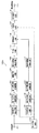
図1に示す第1の実施形態の周波数誤差検出装置100は、受信信号の入力端子101と、既知信号抽出回路102と、第1の分散配置回路103と、第1の周波数変換回路104と、第1の遅延検波回路105と、系列発生回路111と、第2の分散配置回路112と、第2の周波数変換回路113と、第2の遅延検波回路114と、相関演算回路106と、ピーク検出回路107と、周波数誤差信号の出力端子120と、モード判別回路115と、を備える。
A frequency error detection apparatus 100 according to the first embodiment shown in FIG. 1 includes a received
既知信号抽出回路102は、周期的に変化する既知信号が挿入されている受信信号から既知信号を抽出する。
第1の分散配置回路103は、既知信号抽出回路102で抽出した既知信号を固定区間の中に分散配置させる。
第1の周波数変換回路104は、第1の分散配置回路103の出力を周波数変換し周波数領域の信号に変換する。
第1の遅延検波回路105は、第1の周波数変換回路104の出力である周波数領域の信号を遅延検波することにより隣接周波数成分間の位相変動量を算出する。
The known
The first
The first
The first
系列発生回路111は、前述の周期的に変化する既知信号と同じ系列を発生させるものである。
第2の分散配置回路112は、系列発生回路111で発生させた既知信号を固定区間の中に分散配置させる。
第2の周波数変換回路113は、第2の分散配置回路112の出力を周波数変換し周波数領域の信号に変換する。
第2の遅延検波回路114は、第2の周波数変換回路113の出力である周波数領域の信号を遅延検波することにより隣接周波数成分間の位相変動量を算出する。
The
The second
The second
The second
相関演算回路106は、第1の遅延検波回路105の出力と第2の遅延検波回路114の出力との相関値を出力する。
ピーク検出回路107は、相関演算回路106からの相関値のうち電力の大きいピークを1つ以上検出し,基準値からの差分を算出し周波数誤差として出力する。
The
The
図2はDTMBにおける受信信号のフレーム構成とそのフレームのフレームヘッダ(FH)の構成を示している。(a)は受信信号のフレーム構成を示し、(b)は(a)のフレームのフレームヘッダを拡大した構成を示している。放送信号としては、図2(a)のように複数のフレームが連続的に送信されてくる。 FIG. 2 shows a frame structure of a received signal in DTMB and a frame header (FH) structure of the frame. (a) shows the frame configuration of the received signal, and (b) shows the configuration in which the frame header of the frame (a) is expanded. As a broadcast signal, a plurality of frames are continuously transmitted as shown in FIG.
受信信号は周期的に既知の信号が挿入されたフレーム構成の信号である。DTMBのフレームはフレームヘッダ(FH)とフレームボディ(FB)で構成されており、FHにはフレームを識別するための既知の信号(PN系列)が挿入されている。さらに、FHは前半部分の系列の一部Qと後半部分の系列の一部RがPN系列の巡回拡張で構成されるという特徴を持っている。QとQ’は同じものであり、RとR’も同じものである。 The received signal is a signal having a frame structure in which a known signal is periodically inserted. A DTMB frame includes a frame header (FH) and a frame body (FB), and a known signal (PN sequence) for identifying the frame is inserted into the FH. Further, FH has a feature that a part Q of the first half sequence and a part R of the second half sequence are configured by cyclic extension of the PN sequence. Q and Q 'are the same, and R and R' are also the same.
なお、DTMBでは時間領域の既知信号(フレームヘッダ:FH)として3通りのシンボル長さ420, 595, 945に対応した第1,第2,第3の放送モードがある。この第1,第2,第3のモードにおける3つの異なった長さのFHにそれぞれ挿入されている既知信号(PN系列)はシンボル長さ255,595,511を有している。そのうちの第2のモードは、FHとそれに含まれるPN系列は同じ長さとなっている。これらの第1,第2,第3のモードのうちの第2のモードを除いた第1,第3のモードでは、FHに挿入されるPN系列は、連続的に受信される所定数のフレームに関してフレーム毎に一定の規則でFH範囲内で位置的に変動する(これをFH変動という)。
In DTMB, there are first, second, and third broadcast modes corresponding to three
以下の説明では、3つのモードのうちの第1のモード(FH長が420)を具体例として上げて説明する。
図3はFH変動におけるPN系列のシフトの様子を示している。FH変動は図2(b)に示すPN系列が図3のようにフレーム毎に固有の変化量で左右にシフトする。変化量はあるフレーム番号(fr#と記す)を境に少なくなりフレーム周期で変化量は0に戻る。この変動パターンによりフレームを識別することができる。一般的には、フレーム番号fr#は0〜Mとすると、最大のフレーム番号Mは3つのモードごとに異なっている。第1のモード(FH長が420)では、M=224となっている。
In the following description, the first mode (FH length is 420) of the three modes will be described as a specific example.
FIG. 3 shows how the PN sequence shifts in the FH fluctuation. As for FH fluctuation, the PN sequence shown in FIG. 2 (b) is shifted to the left and right by a change amount specific to each frame as shown in FIG. The amount of change decreases with a certain frame number (denoted as fr #) as a boundary, and the amount of change returns to 0 in the frame period. Frames can be identified by this variation pattern. Generally, when the frame number fr # is 0 to M, the maximum frame number M is different for each of the three modes. In the first mode (FH length is 420), M = 224.
第1のモード(FH長が420の場合)に関しては、フレーム番号fr#0〜224の225枚のフレーム数によって形成される期間をスーパーフレームと呼んでいる。図3の例では、PN系列はfr#0から徐々にシフトしていき、fr#112のところで基準より最もずれた状態となり、fr#224で最初のフレーム番号fr#0の位置に戻ってくる。fr#224とfr#0は内容は同じであり、従ってfr#224とfr#0と2フレーム同じPN系列で送信される。
Regarding the first mode (when the FH length is 420), a period formed by the number of 225 frames having frame numbers fr # 0 to 224 is called a super frame. In the example of FIG. 3, the PN sequence is gradually shifted from fr # 0, is most shifted from the reference at fr # 112, and returns to the position of the first frame number fr # 0 at fr # 224. . The contents of fr # 224 and
ここで、モード判別回路115について説明する。
本実施形態の構成においては、第1〜第3の3つの放送モードを判別するモード判別回路115が設けられている。モード判別回路115は、判別された放送モードに対応して既知信号抽出回路102,第1の分散配置回路103,系列発生回路111,第2の分散配置回路112,及びピーク検出回路107を制御し、受信信号の周波数誤差検出を受信モードに適応して行うようにしている。例えば分散配置する際に、モードの情報が必要となるので、先にモードを判定してから周波数誤差を検出することが可能となる。周波数誤差の検出とモードの判定を同時に行うことはできない。
Here, the
In the configuration of the present embodiment, a
モード判別回路115の判定方法としては、例えば、時間領域で受信信号のFHと参照信号(3通り)で相関を取り、最も相関値の高いモードを放送モードと判定する方法がある。
As a determination method of the
従って、3つのモードの放送信号を受信可能とする受信機に用いられる周波数誤差検出装置では、モード判別回路によって、放送信号のモードを自動判別し、判別された放送モードに対応した周波数誤差検出を行うことが可能となる。 Therefore, in a frequency error detection device used in a receiver capable of receiving three modes of broadcast signals, the mode discrimination circuit automatically discriminates the mode of the broadcast signal and detects the frequency error corresponding to the discriminated broadcast mode. Can be done.
次に、図1の動作を説明する。
図1において、受信信号は既知信号抽出回路102に入力され、受信PN系列が抽出される。抽出されたPN系列は、分散配置回路103へ入力される。
Next, the operation of FIG. 1 will be described.
In FIG. 1, a received signal is input to a known
分散配置回路103は、図4に示すように受信PN系列を周波数変換の区間(PN系列長以上)に分散配置して出力する。ここで、周波数変換区間とは、PN系列長以上の固定区間であり、本実施形態ではシンボル長さ3780のフレームボディ(FB)を周波数変換する際に使用する図示しない周波数変換回路の周波数変換区間と同じにしている。図4は受信PN系列をN個(Nは例えばPN系列長と同じシンボル数である)に分割して、図示しないFB用の周波数変換回路における周波数変換の区間内に分散配置した例を示している。図4においては、(a)に示すN個のシンボルからなるPN系列を、(b)に示すように1シンボルごとに、周波数変換区間に均等に分散させている。第1のモードのときは、Nは255シンボルである。周波数変換区間はどのモードについても例えばFB用の周波数変換器の変換区間であるシンボル数3780に固定されているので、分散配置される間隔はモードごとに異なることになる。
As shown in FIG. 4, distributed
受信PN系列が、受信PN系列を分散配置する間の補間方法については、固定値で埋める方法、ランダムな系列値で埋める方法、既知信号抽出回路で抽出した既知信号のデータをコピーする方法などが利用できる。 As for the interpolation method between the received PN sequence and the received PN sequence distributed, there are a method of filling with a fixed value, a method of filling with a random sequence value, a method of copying data of a known signal extracted by a known signal extraction circuit, etc. Available.
第1の周波数変換回路104は、分散配置された受信PN系列をFFTやDFTなどのアルゴリズムにより、時間領域の信号を周波数領域の信号へ変換し出力する。このように、分散配置することによって、PN系列長よりも長い周波数変換器で周波数変換を行う場合(例えばFB用の周波数変換回路(図示略)における周波数変換区間)でも、不連続点(後述する図7B参照)に起因する不要な高周波成分を抑えることができる。第1の遅延検波回路105は分散配置後に周波数領域に変換された受信PN系列の隣接キャリア間の位相差を算出し出力する。第1の遅延検波回路105から出力される隣接キャリア間の位相差は、受信PN系列が基準信号(PN系列)に対する周波数誤差がある場合、その位相差自体が基準の位相差とは異なったものとなって出力される。
The first
一方、系列発生回路111は、受信FHのPN系列と同一の系列を参照信号として発生し出力する。第2の分散配置回路112は受信信号と同様の方法で参照信号を周波数変換の区間に分散配置して出力する。第2の周波数変換回路113は、分散配置された参照信号をFFTやDFTなどのアルゴリズムにより、時間領域の信号を周波数領域の信号へ変換し出力する。第2の遅延検波回路114は分散配置後に周波数領域に変換された参照信号の隣接キャリア間の位相差を算出し出力する。この参照信号の位相差はあらかじめ計算したものを保存しておいて利用することも可能である。
On the other hand, the
相関演算回路106は、受信PN系列の位相差と、参照信号の位相差との相関値を算出し出力する。
図5は相関演算回路の構成及び処理を示している。
相関演算回路106は、参照信号Srの複数のサンプル値を保持する系列保持部116と、受信PN系列Scを1サンプルずつシフトさせながら保持する系列保持部117と、系列保持部116を構成するm個のレジスタ部a-1〜a-mの各サンプル値と系列保持部117を構成するm個のレジスタ部b-1〜b-mの各サンプル値とを対応する同士で互いに乗算するm個の乗算器M1〜Mmと、乗算器M1〜Mmのm個の乗算結果を加算し、相関値として出力する加算器118と、を備えている。なお、受信PN系列側の遅延検波出力、参照信号側の遅延検波出力、及び相関値はいずれも周波数領域での値として得られる。図5に示したデータSc,Srは周波数変換後の波形となる。受信PN系列,参照信号をそれぞれ周波数領域に変換後、周波数領域にて相関演算を行う。
FIG. 5 shows the configuration and processing of the correlation calculation circuit.
The
この構成では、相関演算回路106は受信PN系列Scを1サンプルずつシフトさせながら、参照信号Srとの積和演算を行うことによって相関値が得られる。矢印119はシフト方向を示している。
In this configuration, the
ピーク検出回路107は、相関値より強い電力を持つピークを一つ以上検出し、基準となるピーク位置0との差τより周波数誤差を算出する。ピーク位置0のところには、受信PN系列と参照信号とに周波数誤差がなく両者が一致したときにピークが立つ。両者に周波数誤差があった場合は、図5に示すようにSrに対してScがずれた状態からScを1サンプルずつある固定の量(最大シフト量)までシフトさせる。最大シフト量によって検出可能な最大の周波数誤差が変わってくる。1サンプルずつシフトしながらピークが最大となるまでのシフト量τを測定する。この測定したシフト量τの逆数を演算することによって周波数誤差を算出することができる。
The
ここで、受信PN系列Scを1サンプル分だけシフトしたときの周波数誤差量は、モードごとに相違している。 Here, the frequency error amount when the received PN sequence Sc is shifted by one sample differs for each mode.
次に、図6〜図10を参照して、図1〜図5の構成のうち分散配置によって得られる利点を中心に更に説明する。
図6はDTMBの第1のモード(FH長=420シンボル、PN系列長x=255シンボル)におけるフレーム構成とFHの変動及びそのFH変動時における既知信号(受信PN系列)の抽出処理を説明するものである。フレームヘッダFBの長さに関しては、第1〜第3のモードで共通の3780シンボルである。
Next, with reference to FIGS. 6-10, it demonstrates further focusing on the advantage acquired by distributed arrangement among the structures of FIGS.
FIG. 6 illustrates the frame configuration and FH fluctuation in the first mode of DTMB (FH length = 420 symbols, PN sequence length x = 255 symbols), and extraction processing of a known signal (received PN sequence) at the time of the FH fluctuation. Is. The length of the frame header FB is 3780 symbols common to the first to third modes.
FHは図2に示すように巡回拡張された構成となっているので、FHの範囲内で受信PN系列が図3に示したように変動しても受信PN系列の抽出範囲を図6に示すようにFH長の中央に設定しておけば、PN系列を抽出することが可能である。 Since the FH has a cyclically expanded configuration as shown in FIG. 2, even if the received PN sequence fluctuates as shown in FIG. 3 within the FH range, the extracted range of the received PN sequence is shown in FIG. Thus, if it is set at the center of the FH length, a PN sequence can be extracted.
図7Aは、抽出した受信PN系列xを分散配置することなく、この受信PN系列xを、FB用の周波数変換回路の周波数変換区間(シンボル長3780)の先頭から割り当てた場合の,周波数変換後から見た周波数変換前の系列を示している。この場合、受信PN系列xは255の長さであり、3780−255(=3525)の期間はデータのない期間となるので、固定値0で補間している。ここでは,不連続点を視覚的にわかりやすくするために正弦波を用いて説明している.実際には,図7Bの波形はPN系列になるので0または1の2値になる。周波数変換後から見た周波数変換前の波形Bには、不連続点e,g,hが存在している。 FIG. 7A shows a state after frequency conversion when the received PN sequence x is allocated from the beginning of the frequency conversion section (symbol length 3780) of the FB frequency conversion circuit without distributing the extracted received PN sequence x. Shows a sequence before frequency conversion as seen from FIG. In this case, the received PN sequence x has a length of 255, and the period of 3780-255 (= 3525) is a period without data, so that interpolation is performed with a fixed value of 0. Here, a sine wave is used to explain the discontinuities visually. Actually, since the waveform of FIG. 7B is a PN sequence, it becomes a binary value of 0 or 1. Discontinuous points e, g, and h exist in the waveform B before frequency conversion viewed from after frequency conversion.
図7Cは、受信PN系列を、FB用の周波数変換回路の周波数変換区間(シンボル長3780)に対して分散配置した状態を示している。図7Dは、図7Cの分散配置した状態のPN系列を、FB用の周波数変換回路(兼用)によって周波数変換した後の波形であってその周波数変換後から見た周波数変換前の波形を示している。図7Dの二点鎖線に示す包絡線の波形には図7Bの波形に現れた不連続点e,g,h(特に図7Bに示したフレームとフレームとの各周期の間の不連続点g)はなくなり、滑らかな波形となっている。 FIG. 7C shows a state in which the received PN sequence is distributedly arranged with respect to the frequency conversion section (symbol length 3780) of the FB frequency conversion circuit. FIG. 7D shows a waveform after the frequency conversion of the PN sequence in the dispersed arrangement of FIG. 7C by the FB frequency conversion circuit (also used) and before the frequency conversion viewed from the frequency conversion. Yes. The envelope waveform shown by the two-dot chain line in FIG. 7D includes the discontinuity points e, g, and h appearing in the waveform in FIG. 7B (particularly, the discontinuity points g between the frames shown in FIG. 7B. ) Disappears, and the waveform is smooth.
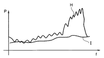
図8は、分散配置することなく周波数変換した場合(図7A,B)における、周波数変換後における周波数特性Hと、分散配置した状態で周波数変換した場合(図7C,D)における、周波数変換後における周波数特性Iとを示している。横軸は周波数f、縦軸はパワーPである。受信PN系列xを分散配置しないときの周波数変換後から見た周波数変換前の波形に、不連続点が存在すると周波数変換後に本来の信号にはない不要な高周波成分が生じる。反対に、周波数変換後から見た周波数変換前の波形に、図7Dに示したように不連続点が存在することなく滑らかになっていることは、周波数変換後の波形Iでは不要な高周波成分が低減されていることを意味している。 8 shows frequency characteristics H after frequency conversion when frequency conversion is performed without distributed arrangement (FIGS. 7A and 7B) and after frequency conversion when frequency conversion is performed in a distributed arrangement (FIGS. 7C and D). The frequency characteristic I is shown in FIG. The horizontal axis is frequency f, and the vertical axis is power P. If a discontinuity exists in the waveform before frequency conversion viewed after frequency conversion when the received PN sequence x is not distributed, unnecessary high-frequency components that are not present in the original signal are generated after frequency conversion. On the contrary, the waveform before frequency conversion seen after frequency conversion is smooth without the presence of discontinuities as shown in FIG. 7D. The high frequency component unnecessary for the waveform I after frequency conversion. Is reduced.
図9において、(a)は受信PN系列の遅延検波後(即ち相関演算前)の周波数特性を示し、(b)は参照信号の遅延検波後(即ち相関演算前)の周波数特性を示している。
遅延検波後における、受信PN系列での周波数特性(a)と参照信号での周波数特性(b)との両者に図9に示すように周波数誤差がなければ、この両者間で図5に示したような相関演算(積和演算)を行うと、図10に示す時間軸上では時間0のところにピークP1が立つことになる。図9(a)及び(b)のように周波数特性が全く同じ状態に対して、図5に示したように受信PN系列が参照信号に対して周波数誤差を生じた状態では、受信PN系列を1サンプルずつシフトさせ(最大ピークまでにシフト量t1を要して)ピークP2が得られたときには、図10に示すように位置0からのシフト量t1がサンプルずれとして測定され、これに基づいて周波数誤差を算出することができる。
In FIG. 9, (a) shows the frequency characteristic after delay detection of the received PN sequence (ie before correlation calculation), and (b) shows the frequency characteristic after delay detection of the reference signal (ie before correlation calculation). .
If there is no frequency error in both the frequency characteristic (a) in the received PN sequence and the frequency characteristic (b) in the reference signal after the delay detection as shown in FIG. 9, they are shown in FIG. When such a correlation operation (product-sum operation) is performed, a peak P1 stands at
3通りの放送モードに対する異なるFH長(又はPN系列長)に対して予め決めた一種類の周波数変換回路の周波数変換区間に分散配置するので、1つの周波数変換回路で処理することができる。
第1の実施形態によれば、既知信号の長さに依存しないで一種類の周波数変換回路で周波数誤差検出できるので、回路規模削減効果が大きい。
Since different FH lengths (or PN sequence lengths) for the three broadcast modes are distributed in the frequency conversion section of one type of frequency conversion circuit determined in advance, processing can be performed with one frequency conversion circuit.
According to the first embodiment, since the frequency error can be detected by one type of frequency conversion circuit without depending on the length of the known signal, the circuit scale reduction effect is great.
本実施形態では、例えばFB長3780のFB用の周波数変換回路を使ってそれよりも短い決まった固定区間(例えば255シンボル区間)のPN系列の周波数変換を行う。分散配置は、変動しているPN系列に対してある決まった固定区間xを抽出することによる不連続点の対策として行っている。補足すると,FHが変動している場合、抽出する区間xで抽出される系列はフレーム毎に異なる。一方,参照信号は固定(例えば図3に示すfr#0の255シンボルの区間)である。xは図2にあるように巡回拡張で生成されているから、連続性を保つように周波数変換ができれば,周波数変換後のxは周波数変換後の参照信号を位相シフトをしただけで同じ信号として扱うことができる。分散配置は、上記の連続性を保つように周波数変換するために行っている。したがって、フレーム番号が未知でかつFHの変動があっても周波数誤差を検出可能である。 In the present embodiment, for example, an FB frequency conversion circuit having an FB length of 3780 is used to perform frequency conversion of a PN sequence in a fixed period (for example, 255 symbol period) shorter than that. The distributed arrangement is performed as a measure for discontinuous points by extracting a certain fixed section x for the changing PN sequence. Supplementally, when FH fluctuates, the series extracted in the section x to be extracted differs from frame to frame. On the other hand, the reference signal is fixed (for example, an interval of 255 symbols of fr # 0 shown in FIG. 3). Since x is generated by cyclic extension as shown in FIG. 2, if frequency conversion can be performed so as to maintain continuity, x after frequency conversion can be regarded as the same signal only by phase shifting the reference signal after frequency conversion. Can be handled. The distributed arrangement is performed for frequency conversion so as to maintain the above continuity. Therefore, the frequency error can be detected even if the frame number is unknown and the FH varies.
[第2の実施形態]
図11は本発明の第2の実施形態の周波数誤差検出装置のブロック図を示している。
図11に示す周波数誤差検出装置100Aは、図1の構成に対して、振幅抑圧回路108と、平均化回路109と、出力選択回路110とを加えた点で異なっている。
[Second Embodiment]
FIG. 11 shows a block diagram of a frequency error detection apparatus according to the second embodiment of the present invention.
The frequency
振幅抑圧回路108は、第1の周波数変換回路104と第1の遅延検波回路105との間に設けられ、第1の周波数変換回路104の出力である周波数領域の信号に基づいて算出した閾値と比較して信号の振幅を抑圧し、第1の遅延検波回路105へ出力する。振幅抑圧回路108は、例えば、周波数領域に変換された受信PN系列の平均電力から閾値を算出し、閾値を越える瞬時電力のキャリアを抑圧する。抑圧方法は閾値でクリッピングする方法や、0にする方法が利用できる。
The
平均化回路109は、第1の遅延検波回路105と相関演算回路106との間に設けられ、第1の遅延検波回路105の出力をフレーム単位で平均化し、相関演算回路106へ出力する。平均化回路109は、例えば、遅延検波回路105の出力をフレーム単位で2フレーム以上平均化し出力する。
The averaging
出力選択回路110は、ピーク検出回路107からの、異なる時間の受信信号より検出した2つ以上の周波数誤差から選択して出力する。出力選択回路110は、例えば、複数のフレームに対して周波数誤差を算出したものを記憶しておき、その中から最終出力として出力する周波数誤差を選択する。選択方法としては、複数の周波数誤差の中から最も頻度の高い周波数誤差を選択する方法や、連続して規定回数同じ周波数誤差が得られた時点でその周波数誤差を選択する方法が考えられる。
The
第2の実施形態によれば、振幅抑圧回路を加えることによって、単一周波数の連続波による妨害(CW妨害)などの妨害波を除去できるので、周波数誤差の検出精度を向上させることができる。
平均化回路を加えることによって、ランダム成分であるノイズを除去し、相関値に含まれるSN比が改善できるので、周波数誤差の検出精度を向上させることができる。
出力選択回路を加えることによって、受信信号の受信品質が劣悪な場合でも複数回検出した結果から最も確からしい出力を選択できるため、周波数誤差を向上させることができる。
According to the second embodiment, by adding an amplitude suppression circuit, interference waves such as interference due to a single frequency continuous wave (CW interference) can be removed, so that the accuracy of frequency error detection can be improved.
By adding an averaging circuit, noise that is a random component can be removed and the S / N ratio included in the correlation value can be improved, so that the frequency error detection accuracy can be improved.
By adding an output selection circuit, even if the reception quality of the received signal is poor, the most probable output can be selected from the results detected a plurality of times, so that the frequency error can be improved.
なお、図11では、図1の装置に対して、振幅抑圧回路108と、平均化回路109と、出力選択回路110と、の3つ回路を設けた構成を示しているが、図1の装置に対してこれらの3つの回路のうちの少なくとも1つを設けた構成であっても、周波数誤差の検出精度を増す効果が得られる。
11 shows a configuration in which three circuits of an
本発明のいくつかの実施形態を説明したが、これらの実施形態は、例として提示したものであり、発明の範囲を限定することは意図していない。これら新規な実施形態は、その他の様々な形態で実施されることが可能であり、発明の要旨を逸脱しない範囲で、種々の省略、置き換え、変更を行うことができる。これらの実施形態やその変形は、発明の範囲や要旨に含まれるとともに、特許請求の範囲に記載された発明とその均等の範囲に含まれる。 Although several embodiments of the present invention have been described, these embodiments are presented by way of example and are not intended to limit the scope of the invention. These novel embodiments can be implemented in various other forms, and various omissions, replacements, and changes can be made without departing from the scope of the invention. These embodiments and modifications thereof are included in the scope and gist of the invention, and are included in the invention described in the claims and the equivalents thereof.
100,100A…周波数誤差検出装置、101…受信信号の入力端子、102…既知信号抽出回路、103…第1の分散配置回路、104…第1の周波数変換回路、105…第1の遅延検波回路、106…相関演算回路、107…ピーク検出回路、108…振幅抑圧回路、109…平均化回路、110…出力選択回路、111…系列発生回路、112…第2の分散配置回路、113…第2の周波数変換回路、114…第2の遅延検波回路、120…周波数誤差信号の出力端子。 DESCRIPTION OF SYMBOLS 100,100A ... Frequency error detection apparatus, 101 ... Received signal input terminal, 102 ... Known signal extraction circuit, 103 ... First dispersion arrangement circuit, 104 ... First frequency conversion circuit, 105 ... First delay detection circuit , 106 ... correlation calculation circuit, 107 ... peak detection circuit, 108 ... amplitude suppression circuit, 109 ... averaging circuit, 110 ... output selection circuit, 111 ... series generation circuit, 112 ... second distributed arrangement circuit, 113 ... second Frequency conversion circuit, 114... Second delay detection circuit, 120... Output terminal of frequency error signal.
Claims (7)
前記既知信号抽出回路で抽出した既知信号を固定区間の中に分散配置させる第1の分散配置回路と、
前記第1の分散配置回路の出力を周波数変換し周波数領域の信号に変換する第1の周波数変換回路と、
前記第1の周波数変換回路の出力である周波数領域の信号を遅延検波することにより隣接周波数成分間の位相変動量を算出する第1の遅延検波回路と、
前記周期的に変化する前記既知信号と同じ系列を発生させる系列発生回路と、
前記系列発生回路で発生させた既知信号を固定区間の中に分散配置させる第2の分散配置回路と、
前記第2の分散配置回路の出力を周波数変換し周波数領域の信号に変換する第2の周波数変換回路と、
前記第2の周波数変換回路の出力である周波数領域の信号を遅延検波することにより隣接周波数成分間の位相変動量を算出する第2の遅延検波回路と、
前記第1の遅延検波回路の出力と前記第2の遅延検波回路の出力との相関値を出力する相関演算回路と、
前記相関値のうち電力の大きいピークを1つ以上検出し,基準値からの差分を算出し周波数誤差として出力するピーク検出回路と、
を具備したことを特徴とする周波数誤差検出装置。 A known signal extraction circuit for extracting a known signal with respect to a received signal into which a known signal that periodically changes is inserted;
A first distributed arrangement circuit that distributes and arranges the known signals extracted by the known signal extraction circuit in a fixed section;
A first frequency conversion circuit for frequency-converting the output of the first distributed arrangement circuit and converting it to a frequency domain signal;
A first delay detection circuit that calculates a phase fluctuation amount between adjacent frequency components by delay detection of a signal in a frequency domain that is an output of the first frequency conversion circuit;
A sequence generation circuit for generating the same sequence as the known signal that periodically changes;
A second distributed arrangement circuit for distributing and arranging known signals generated by the series generation circuit in a fixed section;
A second frequency conversion circuit that converts the frequency of the output of the second distributed arrangement circuit into a signal in the frequency domain;
A second delay detection circuit that calculates a phase fluctuation amount between adjacent frequency components by delay-detecting a signal in a frequency domain that is an output of the second frequency conversion circuit;
A correlation operation circuit that outputs a correlation value between the output of the first delay detection circuit and the output of the second delay detection circuit;
A peak detection circuit that detects one or more peaks with high power among the correlation values, calculates a difference from a reference value, and outputs the difference as a frequency error;
A frequency error detection apparatus comprising:
前記第1の遅延検波回路と前記相関演算回路との間に設けられ、前記第1の遅延検波回路の出力をフレーム単位で平均化し、前記相関演算回路へ出力する平均化回路と、
前記ピーク検出回路からの、異なる時間の前記受信信号より検出した2つ以上の前記周波数誤差から選択して出力する出力選択回路と、
のうちの少なくとも1つの回路をさらに具備したことを特徴とする請求項1に記載の周波数誤差検出装置。 The amplitude of the signal compared with a threshold value provided based on a signal in the frequency domain that is provided between the first frequency conversion circuit and the first delay detection circuit and is an output of the first frequency conversion circuit And an amplitude suppression circuit that outputs the first delay detection circuit to the first delay detection circuit;
An averaging circuit that is provided between the first delay detection circuit and the correlation calculation circuit, averages the output of the first delay detection circuit in units of frames, and outputs the average to the correlation calculation circuit;
An output selection circuit for selecting and outputting two or more frequency errors detected from the received signals at different times from the peak detection circuit;
The frequency error detection device according to claim 1, further comprising at least one of the circuits.
前記固定区間は、データ用の前記周波数変換回路の周波数変換区間であることを特徴とする請求項1乃至5のいずれか1つに記載の周波数誤差検出装置。 The first frequency conversion circuit is also used as a data frequency conversion circuit for frequency converting a data signal included in the reception signal,
6. The frequency error detection apparatus according to claim 1, wherein the fixed section is a frequency conversion section of the frequency conversion circuit for data.
判別された放送モードに対応して受信信号の周波数誤差検出を行うことを特徴とする請求項1乃至6のいずれか1つに記載の周波数誤差検出装置。 A mode discriminating circuit for discriminating a plurality of broadcast modes;
The frequency error detection apparatus according to claim 1, wherein the frequency error of the received signal is detected corresponding to the determined broadcast mode.
Priority Applications (3)
| Application Number | Priority Date | Filing Date | Title |
|---|---|---|---|
| JP2011068479A JP2012205122A (en) | 2011-03-25 | 2011-03-25 | Frequency error detection device |
| US13/233,229 US8581570B2 (en) | 2011-03-25 | 2011-09-15 | Frequency error detection apparatus |
| CN201110278486.1A CN102694572B (en) | 2011-03-25 | 2011-09-19 | Frequency error detection apparatus |
Applications Claiming Priority (1)
| Application Number | Priority Date | Filing Date | Title |
|---|---|---|---|
| JP2011068479A JP2012205122A (en) | 2011-03-25 | 2011-03-25 | Frequency error detection device |
Publications (1)
| Publication Number | Publication Date |
|---|---|
| JP2012205122A true JP2012205122A (en) | 2012-10-22 |
Family
ID=46859868
Family Applications (1)
| Application Number | Title | Priority Date | Filing Date |
|---|---|---|---|
| JP2011068479A Withdrawn JP2012205122A (en) | 2011-03-25 | 2011-03-25 | Frequency error detection device |
Country Status (3)
| Country | Link |
|---|---|
| US (1) | US8581570B2 (en) |
| JP (1) | JP2012205122A (en) |
| CN (1) | CN102694572B (en) |
Cited By (1)
| Publication number | Priority date | Publication date | Assignee | Title |
|---|---|---|---|---|
| CN110674124A (en) * | 2019-09-23 | 2020-01-10 | 珠海格力电器股份有限公司 | Abnormal data detection method and system and intelligent router |
Families Citing this family (2)
| Publication number | Priority date | Publication date | Assignee | Title |
|---|---|---|---|---|
| TWI589137B (en) * | 2015-01-28 | 2017-06-21 | 晨星半導體股份有限公司 | Estimating method and device, sampling frequency offset calculating method, and phase estimating method and device |
| CN112422255A (en) * | 2019-08-22 | 2021-02-26 | 瑞昱半导体股份有限公司 | Detection circuit and operation method |
Family Cites Families (13)
| Publication number | Priority date | Publication date | Assignee | Title |
|---|---|---|---|---|
| JP3238120B2 (en) * | 1997-01-31 | 2001-12-10 | 株式会社次世代デジタルテレビジョン放送システム研究所 | Orthogonal frequency division multiplex signal demodulator |
| CN1135763C (en) * | 1997-07-31 | 2004-01-21 | 松下电器产业株式会社 | Quadrature frequency division multiplexing remodulator |
| US6487252B1 (en) * | 1999-01-29 | 2002-11-26 | Motorola, Inc. | Wireless communication system and method for synchronization |
| JP2003304217A (en) | 2002-04-10 | 2003-10-24 | Kddi Corp | Device and method for correcting transmission signal |
| KR100630043B1 (en) * | 2003-11-06 | 2006-09-27 | 삼성전자주식회사 | Frequency error detector and frequency error combiner for receiver in a mobile communication system |
| FI20075282A0 (en) * | 2007-04-23 | 2007-04-23 | Nokia Corp | Frequency error estimation algorithm |
| JP2009088984A (en) * | 2007-09-28 | 2009-04-23 | Kyocera Corp | Reception device, radio communication terminal, radio base station and reception method |
| JP2010193195A (en) | 2009-02-18 | 2010-09-02 | Toshiba Corp | Frequency error detecting circuit, and frequency error detecting method |
| JP5208815B2 (en) | 2009-03-03 | 2013-06-12 | 株式会社東芝 | Frame number detection device |
| JP5462260B2 (en) * | 2009-07-02 | 2014-04-02 | パナソニック株式会社 | Receiving device, integrated circuit, receiving method, and receiving program |
| JP4940275B2 (en) | 2009-08-04 | 2012-05-30 | 株式会社東芝 | Transmission line response estimator |
| JP5032538B2 (en) | 2009-08-28 | 2012-09-26 | 株式会社東芝 | Transmission line response estimator |
| JP2011176742A (en) | 2010-02-25 | 2011-09-08 | Toshiba Corp | Channel response estimator |
-
2011
- 2011-03-25 JP JP2011068479A patent/JP2012205122A/en not_active Withdrawn
- 2011-09-15 US US13/233,229 patent/US8581570B2/en active Active
- 2011-09-19 CN CN201110278486.1A patent/CN102694572B/en active Active
Cited By (2)
| Publication number | Priority date | Publication date | Assignee | Title |
|---|---|---|---|---|
| CN110674124A (en) * | 2019-09-23 | 2020-01-10 | 珠海格力电器股份有限公司 | Abnormal data detection method and system and intelligent router |
| CN110674124B (en) * | 2019-09-23 | 2022-04-12 | 珠海格力电器股份有限公司 | Abnormal data detection method and system and intelligent router |
Also Published As
| Publication number | Publication date |
|---|---|
| CN102694572A (en) | 2012-09-26 |
| US20120242324A1 (en) | 2012-09-27 |
| US8581570B2 (en) | 2013-11-12 |
| CN102694572B (en) | 2014-07-09 |
Similar Documents
| Publication | Publication Date | Title |
|---|---|---|
| JP6118616B2 (en) | Receiver and synchronization correction method | |
| KR100453031B1 (en) | OFDM receiver coarse frequency offset estimation device and method thereof | |
| US7751351B2 (en) | Disturbing signal detecting device for detecting a disturbing signal and OFDM receiver using the same | |
| JP4584756B2 (en) | Pilot signal detection apparatus and method | |
| US7616723B2 (en) | Method for symbol timing synchronization and apparatus thereof | |
| US20050063297A1 (en) | Receiver for burst signal including known signal | |
| JP2005102169A (en) | Method and system for receiving ofdm | |
| JP5208815B2 (en) | Frame number detection device | |
| JP4903026B2 (en) | Delay profile analysis circuit and apparatus using the same | |
| JP2012205122A (en) | Frequency error detection device | |
| JP2005160033A (en) | Ofdm demodulator, integrated circuit for ofdm demodulation, and ofdm demodulation method | |
| GB2540596A (en) | Receiver and method of receiving | |
| JP5411659B2 (en) | Multipath distortion equalization apparatus and reception apparatus in OFDM signal reception | |
| JP2005167594A (en) | Signal generator and signal generating method | |
| JP2003152674A (en) | Frequency synchronization method and ofdm receiver using the same | |
| JP6422421B2 (en) | Synchronization timing control device, synchronization timing control method, and receiver | |
| JP5660444B2 (en) | Spectrum detection apparatus and spectrum detection method | |
| US8588345B1 (en) | Orthogonal frequency division multiplexing receiver | |
| JP7289737B2 (en) | Data transmission system and data transmission method | |
| JP4102348B2 (en) | OFDM wave delay profile measuring device | |
| KR101256864B1 (en) | Ofdm receiver and receving method which can receive single-carrier transmission signal with guard period for long delay spread of channel | |
| EP2077014A2 (en) | Determining symbol synchronization information for ofdm signals | |
| EP1715604B1 (en) | Apparatus and method for detecting transmission mode for digital broadcasting receiver | |
| KR100230847B1 (en) | Orthogonal frequency division multiplexing receiving system | |
| JP3717476B2 (en) | Method and apparatus for detecting carrier frequency error of orthogonal frequency division multiplexed signal |
Legal Events
| Date | Code | Title | Description |
|---|---|---|---|
| A300 | Application deemed to be withdrawn because no request for examination was validly filed |
Free format text: JAPANESE INTERMEDIATE CODE: A300 Effective date: 20140603 |