JP2012202323A - Scroll shape of centrifugal compressor - Google Patents
Scroll shape of centrifugal compressor Download PDFInfo
- Publication number
- JP2012202323A JP2012202323A JP2011068490A JP2011068490A JP2012202323A JP 2012202323 A JP2012202323 A JP 2012202323A JP 2011068490 A JP2011068490 A JP 2011068490A JP 2011068490 A JP2011068490 A JP 2011068490A JP 2012202323 A JP2012202323 A JP 2012202323A
- Authority
- JP
- Japan
- Prior art keywords
- scroll
- cross
- fluid
- sectional area
- ratio
- Prior art date
- Legal status (The legal status is an assumption and is not a legal conclusion. Google has not performed a legal analysis and makes no representation as to the accuracy of the status listed.)
- Granted
Links
Images


Classifications
-
- F—MECHANICAL ENGINEERING; LIGHTING; HEATING; WEAPONS; BLASTING
- F04—POSITIVE - DISPLACEMENT MACHINES FOR LIQUIDS; PUMPS FOR LIQUIDS OR ELASTIC FLUIDS
- F04D—NON-POSITIVE-DISPLACEMENT PUMPS
- F04D29/00—Details, component parts, or accessories
- F04D29/40—Casings; Connections of working fluid
- F04D29/42—Casings; Connections of working fluid for radial or helico-centrifugal pumps
- F04D29/4206—Casings; Connections of working fluid for radial or helico-centrifugal pumps especially adapted for elastic fluid pumps
-
- F—MECHANICAL ENGINEERING; LIGHTING; HEATING; WEAPONS; BLASTING
- F04—POSITIVE - DISPLACEMENT MACHINES FOR LIQUIDS; PUMPS FOR LIQUIDS OR ELASTIC FLUIDS
- F04D—NON-POSITIVE-DISPLACEMENT PUMPS
- F04D29/00—Details, component parts, or accessories
- F04D29/40—Casings; Connections of working fluid
- F04D29/403—Casings; Connections of working fluid especially adapted for elastic fluid pumps
-
- F—MECHANICAL ENGINEERING; LIGHTING; HEATING; WEAPONS; BLASTING
- F04—POSITIVE - DISPLACEMENT MACHINES FOR LIQUIDS; PUMPS FOR LIQUIDS OR ELASTIC FLUIDS
- F04D—NON-POSITIVE-DISPLACEMENT PUMPS
- F04D29/00—Details, component parts, or accessories
- F04D29/40—Casings; Connections of working fluid
- F04D29/42—Casings; Connections of working fluid for radial or helico-centrifugal pumps
- F04D29/4206—Casings; Connections of working fluid for radial or helico-centrifugal pumps especially adapted for elastic fluid pumps
- F04D29/4226—Fan casings
-
- F—MECHANICAL ENGINEERING; LIGHTING; HEATING; WEAPONS; BLASTING
- F04—POSITIVE - DISPLACEMENT MACHINES FOR LIQUIDS; PUMPS FOR LIQUIDS OR ELASTIC FLUIDS
- F04D—NON-POSITIVE-DISPLACEMENT PUMPS
- F04D29/00—Details, component parts, or accessories
- F04D29/40—Casings; Connections of working fluid
- F04D29/42—Casings; Connections of working fluid for radial or helico-centrifugal pumps
- F04D29/44—Fluid-guiding means, e.g. diffusers
- F04D29/441—Fluid-guiding means, e.g. diffusers especially adapted for elastic fluid pumps
-
- F—MECHANICAL ENGINEERING; LIGHTING; HEATING; WEAPONS; BLASTING
- F04—POSITIVE - DISPLACEMENT MACHINES FOR LIQUIDS; PUMPS FOR LIQUIDS OR ELASTIC FLUIDS
- F04D—NON-POSITIVE-DISPLACEMENT PUMPS
- F04D29/00—Details, component parts, or accessories
- F04D29/66—Combating cavitation, whirls, noise, vibration or the like; Balancing
- F04D29/68—Combating cavitation, whirls, noise, vibration or the like; Balancing by influencing boundary layers
- F04D29/681—Combating cavitation, whirls, noise, vibration or the like; Balancing by influencing boundary layers especially adapted for elastic fluid pumps
-
- F—MECHANICAL ENGINEERING; LIGHTING; HEATING; WEAPONS; BLASTING
- F05—INDEXING SCHEMES RELATING TO ENGINES OR PUMPS IN VARIOUS SUBCLASSES OF CLASSES F01-F04
- F05D—INDEXING SCHEME FOR ASPECTS RELATING TO NON-POSITIVE-DISPLACEMENT MACHINES OR ENGINES, GAS-TURBINES OR JET-PROPULSION PLANTS
- F05D2250/00—Geometry
- F05D2250/50—Inlet or outlet
- F05D2250/52—Outlet
Landscapes
- Engineering & Computer Science (AREA)
- Mechanical Engineering (AREA)
- General Engineering & Computer Science (AREA)
- Structures Of Non-Positive Displacement Pumps (AREA)
Abstract
Description
本発明は、コンプレッサインペラの回転によって、該コンプレッサインペラの外周部に渦巻形状に形成された流路を構成するスクロール部を備えた遠心圧縮機に関し、スクロール部において流体(気体)の静圧を回復させるスクロール形状に関する。 The present invention relates to a centrifugal compressor provided with a scroll portion that forms a spiral flow path on the outer periphery of a compressor impeller by rotation of the compressor impeller, and recovers the static pressure of fluid (gas) in the scroll portion. It relates to the scroll shape.
遠心圧縮機は広い運転範囲において高圧力、高効率化であることが求められている。
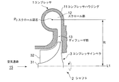
図7は、遠心圧縮機におけるコンプレッサインペラの回転軸心上半分の要部拡大断面図を示している。
遠心圧縮機のコンプレッサ1は、主に回転するハブ31及びその外周面に取付けられた多数の遠心羽根32で構成されているコンプレッサインペラ3と、該コンプレッサインペラ3の回転駆動源と連結したシャフト2と、それらを収納すると共に、流体の流路を形成するコンプレッサハウジング11と、で構成されている。
コンプレッサハウジング11は、コンプレッサインペラ3の外周側に略ドーナツ状を成して、コンプレッサインペラ3から吐出される流体を減速させることによって、静圧を回復させるディフューザ部13、その外周側に、断面積が周方向に向かい渦巻状に拡大するように形成され、全周にわたって気体を集めるスクロール部12及び出口管(図示省略)が設けられている。
Centrifugal compressors are required to have high pressure and high efficiency over a wide operating range.
FIG. 7 shows an enlarged cross-sectional view of the main part of the half on the rotational axis of the compressor impeller in the centrifugal compressor.
The compressor 1 of the centrifugal compressor includes a
The compressor housing 11 has a substantially donut shape on the outer peripheral side of the
コンプレッサインペラ3が回転すると、遠心羽根32が空気通路15から導入したガスや空気等の流体を圧縮する。こうして形成された流体の流れ(流体)は、コンプレッサインペラ3の外周端からディフューザ部13及びスクロール部12を通って出口管から外部へ送出される。
When the compressor impeller 3 rotates, the
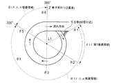
図8は、スクロール部12の平面視の一例を示す概略図である。
スクロール部12は、スクロール終点(図8の360°)を0基準にして、時計回りに60°の位置から30°毎に位置を決めた半径R(スクロール部12断面の図芯P0とシャフト2の軸心L1)分布は一定になっている。
図9(A)には、横軸に周方向毎の角度位置を示し、縦軸にスクロール部12のコンプレッサ回転軸の軸心L1からスクロール断面の図芯Pまでの半径Rを示し、半径Rの分布は一定になっていることを示している。
また、図9(B)は、図8において時計回りに60°の位置を基準にしたスクロール部12の周方向位置毎(30°毎)における各断面を積層して表示した断層図で、スクロール断面の図芯P0の半径R方向の変化を表わしたものである。
スクロール部12には、スクロール部12の略全周にわたりコンプレッサインペラ3からの流体(気体)がディフューザ部13を介して流入するので、スクロール部12の各断面積は流体の流入量に応じて流体が流れる方向に沿って一定の比率χで大きくなっている。
そして、スクロール部12の断面積の拡大比率χ(一定比率)とディフューザ部13からスクロール部12内への流体流入量の増大率のバランスが合ったときにスクロール内の流体速度が一定になる。
FIG. 8 is a schematic diagram illustrating an example of a plan view of the
The
In FIG. 9A, the horizontal axis indicates the angular position for each circumferential direction, and the vertical axis indicates the radius R from the axis L1 of the compressor rotation shaft of the
Further, FIG. 9B is a tomogram in which the respective cross sections at each circumferential position (every 30 °) of the
Since the fluid (gas) from the
The fluid velocity in the scroll becomes constant when the expansion ratio χ (constant ratio) of the cross-sectional area of the
スクロールの形状を変化させた従来技術として、特開2010−209824号公報(特許文献1)が開示されている。
特許文献1は、流体ガスを動翼に供給して動力を得るタービンの動翼の回転軸周りに渦巻状に形成された流路を備えたスクロール部の断面形状が角丸四角形状から円形状に移行しながら断面積が漸減する第一移行部を有し、該第一移行部の角部の曲率半径は実質的に同一の大きさに構成されている。
そして、第一移行部を形成したことにより、スクロール断面を大きくできる位相では角丸四角形状とし、スクロール断面を大きくできない位相では円形状として、各位相において十分な流路断面積を確保すると共に、流体の圧力損失を低減することができる技術開示がなされている。
Japanese Unexamined Patent Application Publication No. 2010-209824 (Patent Document 1) is disclosed as a conventional technique in which the scroll shape is changed.
In Patent Document 1, the cross-sectional shape of a scroll portion provided with a flow path formed in a spiral shape around the rotating shaft of a turbine blade that supplies power by supplying a fluid gas to the blade is changed from a rounded quadrangular shape to a circular shape. The first transition portion where the cross-sectional area gradually decreases while transitioning to (1), the radius of curvature of the corner portion of the first transition portion is configured to be substantially the same size.
And, by forming the first transition part, in the phase that can increase the scroll cross section is a rounded square shape, in the phase that can not increase the scroll cross section is a circular shape, while ensuring a sufficient cross-sectional area in each phase, There are technical disclosures that can reduce the pressure loss of a fluid.
しかし、特許文献1の技術においては、流体ガスを動翼に供給して膨張しながら動力を得るタービンのスクロール形状であり、流体(気体)を圧縮する本願の場合とでは流体の流れ方、及び性質が異なる。
従って、スクロール形状の考え方も異なるものである。
また、遠心圧縮機は広範囲で高出力比、高効率化であることが求められている。
圧縮機から流出する流体が速度を持つ場合、動圧力の上昇は得られるものの静圧力の上昇が得られ難いため圧力比及び効率が低下する。そのため、圧縮機内で速度を落とすことが求められる。ディフューザ部では流体の速度を落とすことで圧力を回復するが、スクロール部の各部位の断面において、流体の速度はスクロールの内側及び外側では流体速度がかわり、正確な流量及び速度を求め難い。
また、スクロール部で流体の減速を行う場合には、スクロール部の断面の大きさを線形的(一定比率)で増加させることが考えられる。この場合は流れ方向に一定の減速を与えており流体とスクロール部壁面との間の境界層が厚くなり静圧回復が十分に得られないと共に、サージングの発生による作動範囲の縮小や過給効率の低下の不具合をまねく。
However, in the technique of Patent Document 1, it is a scroll shape of a turbine that obtains power while supplying fluid gas to a moving blade and expanding, and in the case of the present application in which fluid (gas) is compressed, The nature is different.
Therefore, the concept of the scroll shape is also different.
Further, the centrifugal compressor is required to have a high output ratio and high efficiency in a wide range.
When the fluid flowing out of the compressor has a velocity, although the dynamic pressure can be increased, it is difficult to increase the static pressure, so the pressure ratio and efficiency are reduced. Therefore, it is required to reduce the speed in the compressor. In the diffuser section, the pressure is recovered by reducing the fluid speed. However, in the cross-section of each part of the scroll section, the fluid speed varies between the inside and outside of the scroll, and it is difficult to obtain an accurate flow rate and speed.
Further, when the fluid is decelerated at the scroll portion, it is conceivable to increase the size of the cross section of the scroll portion linearly (at a constant ratio). In this case, a constant deceleration is applied in the flow direction, the boundary layer between the fluid and the scroll wall becomes thick, and sufficient static pressure recovery cannot be obtained. This leads to a drop in the malfunction.
本発明はこのような問題点を解決するためになされたもので、スクロール部の断面積を舌部からスクロール部の周方向の任意の角度まで前記断面積の拡大比率をスクロール部を流れる流体の流入量増大に応じた拡大比率より漸次拡大させその後、任意角度からスクロール部の巻き終りまでの前記断面積の拡大比率を減少させることにより、スクロール内で流体の流れを減速させる部分と増速させる部分を作り、十分な静圧回復ができるようにして、遠心圧縮機としての高い効率、高い圧力を得られるようにすることを目的とする。 The present invention has been made to solve such problems. The cross-sectional area of the scroll portion is increased from the tongue portion to an arbitrary angle in the circumferential direction of the scroll portion. By gradually increasing the expansion ratio according to the increase in inflow amount, and then decreasing the expansion ratio of the cross-sectional area from an arbitrary angle to the end of winding of the scroll portion, the speed of the fluid flow in the scroll is increased. The purpose is to make a part and recover a sufficient static pressure so as to obtain high efficiency and high pressure as a centrifugal compressor.
本発明はかかる課題を解決するため、遠心圧縮機のコンプレッサインペラの下流側に配設されたディフューザ部から吐出されたガス又は空気等の流体の流路を形成する遠心圧縮機のスクロール形状において、
スクロール部の断面積Aと、前記コンプレッサインペラの軸心からスクロール部断面の図芯までの半径Rとの比A/Rの前記スクロール角度の増大に伴う拡大比率が前記スクロール部の巻き始めから巻き終りまでを減少させるようにしたことを特徴とする。
In order to solve such a problem, the present invention provides a scroll shape of a centrifugal compressor that forms a flow path of a fluid such as gas or air discharged from a diffuser portion disposed downstream of a compressor impeller of the centrifugal compressor.
The ratio A / R of the ratio A / R between the cross-sectional area A of the scroll portion and the radius R from the axis of the compressor impeller to the center of the cross-section of the scroll portion is increased from the start of winding the scroll portion. It is characterized by decreasing to the end.
また、本発明において好ましくは、前記比A/Rは、前記スクロール部断面を半径一定riの帯状領域の断面積Aiに分割し、半径riと断面積Aiとの比Ai/riの総和として算出するようにするとよい。 In the present invention, preferably, the ratio A / R is calculated as a sum of ratios Ai / ri of the radius ri and the cross-sectional area Ai by dividing the cross-section of the scroll portion into a cross-sectional area Ai of a belt-like region having a constant radius ri. It is good to do.
このような構成により、スクロール断面が図芯を中心にしてラジアル方向に対称形状にならない場合が多く、外周側と内周側では流体の速度が異なるが、そのような場合でも、精度の高い流体の体積流量を算出するようにして、流体速度を減速させて、圧力の回復を得ると共に、スクロール巻き終り付近の流体速度を増速させて、スクロール部壁面と流体との境界層の発達を防ぎ、損失の低減(流量抵抗の減少、圧力比向上)と流れの安定化を図ることができる。 With such a configuration, the scroll cross-section often does not have a symmetrical shape in the radial direction around the center of the figure, and the fluid speed is different between the outer peripheral side and the inner peripheral side. By calculating the volume flow rate of the cylinder, the fluid velocity is reduced to recover the pressure, and the fluid velocity near the end of the scroll winding is increased to prevent the development of the boundary layer between the scroll wall surface and the fluid. , Reduction of loss (reduction of flow resistance, improvement of pressure ratio) and stabilization of flow can be achieved.
また、本発明において好ましくは、前記スクロール部の断面積を前記スクロール部の舌部から前記スクロール部の巻き方向任意の角度まで漸次拡大させて、前記流体の速度を減少させる減速領域と、前記任意の角度から前記スクロール部の巻き終りまでの前記断面積の拡大比率を前記減速領域より減少させることにより前記流体の速度を増加させる増速領域とを備えるとよい。 Preferably, in the present invention, the cross-sectional area of the scroll portion is gradually enlarged from the tongue portion of the scroll portion to an arbitrary angle in the winding direction of the scroll portion to reduce the fluid velocity, and the optional It is good to provide the acceleration area | region which increases the speed of the said fluid by reducing the expansion ratio of the said cross-sectional area from the said angle to the end of winding of the said scroll part from the said deceleration area | region.
このような構成により、スクロール巻き始めから任意角度までスクロール部の断面積の拡大比率が前記スクロール部を流れる流体の流入量の増大に応じた拡大比率より大きく維持させることで流体速度を減速させて、圧力の回復を得ると共に、任意角度からスクロール巻き終り付近の断面積拡大比率が前記スクロール部を流れる流体の流入量の増大に応じた拡大比率より小さくすることにより、流体速度を増速させて、スクロール部壁面と流体との境界層の発達を防ぎ、損失の低減(流量抵抗の減少、圧力比向上)と流れの安定化を図ることができる。 With such a configuration, the fluid velocity is reduced by maintaining the enlargement ratio of the cross-sectional area of the scroll part from the scroll winding start to an arbitrary angle larger than the enlargement ratio corresponding to the increase of the inflow amount of the fluid flowing through the scroll part. In addition to recovering the pressure, the fluid velocity is increased by making the cross-sectional area expansion ratio near the end of the scroll winding from an arbitrary angle smaller than the expansion ratio corresponding to the increase in the amount of inflow of the fluid flowing through the scroll portion. The development of the boundary layer between the scroll wall and the fluid can be prevented, loss can be reduced (reduction in flow resistance, improvement in pressure ratio), and flow can be stabilized.
更に、本発明において好ましくは、前記スクロール部の巻き始めから巻き終わりを右側に行くに連れ増加する横軸と、スクロール半径Rと断面積Aとの比A/Rが上部に行くに連れ増加する縦軸とを有する座標軸に、スクロール断面のA/Rの分布を表示した時に、A/Rの分布が上に凸形状となるとよい。 Further, in the present invention, preferably, the ratio A / R between the horizontal axis that increases from the start of winding of the scroll portion to the right end of the scroll portion and the scroll radius R and the cross-sectional area A increases as it goes upward. When the A / R distribution of the scroll section is displayed on the coordinate axis having the vertical axis, the A / R distribution is preferably convex upward.
スクロール部の巻き方向を横軸に、スクロール半径Rと断面積Aとの比A/Rを縦軸にした座標軸において、A/Rが凸形状となる流体速度特性曲線にすることにより、凸形状の頂部までを圧力の回復範囲とし、頂部から拡大比率を減少させた範囲を流体速度増速範囲とするような特性にすることにより、スクロール部壁面と流体との境界層の発達を防ぎ、損失の低減(流量抵抗の減少、圧力比向上)効果を得ることができる。 By forming a fluid velocity characteristic curve in which the A / R has a convex shape on the coordinate axis with the scroll axis winding direction on the horizontal axis and the ratio A / R between the scroll radius R and the cross-sectional area A on the vertical axis, By making the pressure recovery range from the top to the fluid velocity increase range from the top the range where the expansion ratio is reduced, the boundary layer between the scroll wall and the fluid is prevented from developing and lost. Can be obtained (reduction in flow resistance, improvement in pressure ratio).
また、本発明において好ましくは、前記任意の角度は前記スクロール巻き終りを0(ゼロ)基準としてスクロール内の流体が流れる方向に300〜330°の領域とするとよい。 In the present invention, it is preferable that the arbitrary angle be in a range of 300 to 330 ° in a direction in which the fluid in the scroll flows with the scroll winding end as a zero (zero) reference.
このような構成により、流体速度を減速させて、圧力回復領域を可能な限り大きくすると共に、スクロール終点部までの流体を加速させるための最小限必要な領域を確保して、遠心圧縮機としての効率及び、圧縮比を向上させる With such a configuration, the fluid velocity is reduced, the pressure recovery region is increased as much as possible, and the minimum necessary region for accelerating the fluid to the scroll end point is ensured. Improve efficiency and compression ratio
また、本発明において好ましくは、前記舌部近傍の前記スクロール部断面積の拡大比率を、前記減速領域より小さくするとよい。 In the present invention, it is preferable that an enlargement ratio of the cross-sectional area of the scroll portion in the vicinity of the tongue portion is smaller than that of the deceleration region.
このような構成により、舌部近傍では、舌部による流体の剥離が発生するので、当該部の断面積を漸次拡大部分の比率より小さくして、剥離に起因する流体流量損失を低減し、遠心圧縮機としての効率及び、圧縮比を向上させると共に、作動レンジの拡大をはかる。 With such a configuration, fluid separation by the tongue occurs in the vicinity of the tongue, so that the cross-sectional area of the portion is gradually made smaller than the ratio of the enlarged portion to reduce fluid flow loss caused by separation and centrifugal separation. While improving the efficiency and compression ratio as a compressor, the operating range is expanded.
また、本発明において好ましくは、前記舌部近傍の断面積を前記減速領域の比率より小さくする領域は、前記舌部からスクロール方向に略30°〜60°とするとよい。 In the present invention, it is preferable that the region where the cross-sectional area in the vicinity of the tongue portion is smaller than the ratio of the deceleration region is approximately 30 ° to 60 ° in the scroll direction from the tongue portion.
このような構成により、舌部による流体の剥離の影響を受けない領域を求め、流体速度を減少させる圧力回復領域を可能な限り大きくして、遠心圧縮機の性能向上を図る。 With such a configuration, an area that is not affected by fluid separation by the tongue is obtained, and the pressure recovery area for reducing the fluid velocity is increased as much as possible to improve the performance of the centrifugal compressor.
また、本発明において好ましくは、前記スクロール部を流れる流体速度を減少させるため、前記スクロール部の断面積の拡大比率は一定にして、前記断面の図芯と前記スクロール部中心との半径を変化させるとよい。 Preferably, in the present invention, in order to reduce the fluid velocity flowing through the scroll part, the enlargement ratio of the cross-sectional area of the scroll part is constant, and the radius between the centroid of the cross-section and the center of the scroll part is changed. Good.
また、本発明において好ましくは、前記スクロール部を流れる流体速度を減少させるため、前記スクロール部断面の図芯と前記スクロール部中心との半径を一定にして、前記断面積の拡大比率を変化させるとよい。 Preferably, in the present invention, in order to reduce the velocity of fluid flowing through the scroll portion, the radius of the scroll portion cross-section and the center of the scroll portion is made constant, and the enlargement ratio of the cross-sectional area is changed. Good.
スクロール部の断面積を舌部からスクロール部の周方向任意の角度まで漸次拡大させて、任意角度からスクロール部の巻き終りまでの前記断面積の拡大比率を減少させることにより、スクロール部内で流体の流れを減速させる部分と増速させる部分を作り、十分な静圧回復ができるようにして、遠心圧縮機としての高い効率、高い圧力を得られる。 By gradually increasing the cross-sectional area of the scroll part from the tongue part to an arbitrary angle in the circumferential direction of the scroll part, and reducing the expansion ratio of the cross-sectional area from the arbitrary angle to the end of winding of the scroll part, the fluid in the scroll part By creating a part that decelerates the flow and a part that accelerates the flow so that sufficient static pressure can be recovered, high efficiency and high pressure as a centrifugal compressor can be obtained.
以下、本発明を図に示した実施例を用いて詳細に説明する。
但し、この実施例に記載されている構成部品の寸法、材質、形状、その相対配置などは特に特定的な記載がない限り、この発明の範囲をそれのみに限定する趣旨ではなく、単なる説明例にすぎない。
Hereinafter, the present invention will be described in detail with reference to the embodiments shown in the drawings.
However, the dimensions, materials, shapes, relative arrangements, and the like of the component parts described in this example are not intended to limit the scope of the present invention only to specific examples unless otherwise specified. Only.
(第1実施形態)
図7に示すように、本発明のスクロールは、流体の流路として、コンプレッサインペラ3の外周側に略ドーナツ状を成して、コンプレッサインペラ3から吐出される流体(気体)を減速させることによって、静圧を回復させるディフューザ部13、その外周側に、断面積が巻き方向(流体が流れる方向)に向かい渦巻状に拡大するように形成され、流体を減速、昇圧するスクロール部12及び出口管(図示省略)が設けられている。
(First embodiment)
As shown in FIG. 7, the scroll of the present invention forms a substantially donut shape on the outer peripheral side of the
コンプレッサインペラ3が回転すると、遠心羽根32が空気通路15から導入したガスや空気等の流体を圧縮する。こうして形成された流体(気体)の流れは、コンプレッサインペラ3の外周端からディフューザ部13及びスクロール部12を通って出口管から外部へ送出される。
When the
図1、図2及び、図3(A),(B)、(C)に基づいて、本発明の第1実施形態に係る遠心圧縮機のスクロール形状について説明する。
図1は、スクロール部12を平面視したものである。
スクロール形状は、スクロール部12のラジアル方向断面は略円形をしており、該断面の面積はスクロール部終点Z(360°)を0基準として、巻き方向に60°の位置からスクロール部終点Zまでの間、渦巻状に漸次拡大している。(以後、「スクロール部断面」はスクロール部12内の空気体路の軸線に対して直角方向の断面とする。)
また、図1の巻き方向の略60°位置付近には、スクロール部12の巻き始め位置に略一致する部位で且つ、ディフューザ部13から突出される流体とスクロールを流れてきた流体との隔壁端縁である舌部5が配設されている。
The scroll shape of the centrifugal compressor according to the first embodiment of the present invention will be described based on FIGS. 1, 2 and 3 (A), (B), and (C).
FIG. 1 is a plan view of the
As for the scroll shape, the radial cross section of the
Further, in the vicinity of the position of about 60 ° in the winding direction in FIG. 1, the partition wall end of the fluid projecting from the
そして、スクロール部12には、図3(B)、(C)に示すように、流体の速度を落として、静圧を回復する減速領域αと、流体の速度を上げて,流動の安定化を図る増速領域βとを有している。
通常、スクロール部12内を流れる流体(気体)は角運動量が一定であることを条件として以下の式が多用されている。
Vθ×r=一定・・・・・・・・(1)
Vθ:周方向速度
r:半径(インペラ外形)
ところが、スクロール部12の各部位における断面の内側と外側とでは、流体の速度が(1)式からも明らかなように、内側の方が、外側より速くなっている。
従って、スクロール部12内を流れる流体の体積流量Qは断面の大きさ(形状)とスクロールの半径を考慮する必要がある。
そのため、図2に示すようにスクロール断面を半径一定riの帯状の領域(断面積Ai)に分割して(1)式より体積流量Qは次式で求められる。

定数(設計時に決まる)とみなすことができる。
従って、
そこで、
Q=Vθ・r・A/R ・・・・・・(5)
として表わせる。スクロールの各断面を通過する流量Qは各断面において一定とすると、流速はその半径Rの比A/Rによって決まり、A/Rが大きいと流速は減少する。
また、Rが一定でAを小さくすると、そこを流れる流体の速度は増大する。
As shown in FIGS. 3B and 3C, the
Usually, the following formula is frequently used on condition that the fluid (gas) flowing in the
Vθ × r = constant (1)
Vθ: circumferential speed
r: Radius (impeller profile)
However, at the inside and outside of the cross section at each part of the
Accordingly, the volume flow rate Q of the fluid flowing in the
Therefore, as shown in FIG. 2, the scroll cross section is divided into strip-shaped regions (cross-sectional area Ai) having a constant radius ri, and the volume flow rate Q is obtained by the following equation from equation (1).
It can be regarded as a constant (determined at the time of design).
Therefore,
there,
Q = Vθ · r · A / R (5)
Can be expressed as If the flow rate Q passing through each cross section of the scroll is constant in each cross section, the flow velocity is determined by the ratio A / R of the radius R, and the flow velocity decreases when A / R is large.
Further, when R is constant and A is reduced, the velocity of the fluid flowing therethrough increases.
そして、図3(A)は、本実施形態における巻き方向(流体の流れる方向)の各部位におけるスクロール部断面を積層して表示した断層図で、A/Rの断面積拡大比率を変えた場合の分布を示し、図1に示すスクロールの周方向の各部位θ1、θ2、θ3、θ4、θ5及び、θ6までの断面を積層したものである。
スクロール部12には、スクロール部12の略全周にわたりコンプレッサインペラ3からの流体(気体)がディフューザ部13を介して流入する。
従って、本実施形態では、スクロール部12の各断面におけるA/Rを、スクロール角度の増大に伴う断面積拡大比率(d(A/R)/dθ)がスクロール部12を流れる流体の流入量に応じた従来スクロール設計に基づく一定の拡大比率を基準比率χ(閾値)にして、断面積拡大比率を増減させて調整するものである。
各層間の間隔の大きさが面積拡大比率の大きさを表わしている。
図3(B)に横軸にスクロールの巻き方向の角度を示すθと、縦軸に断面積の大きさを表わすA/Rの比を示し、A/Rの変化と共に流体が減速および増速する流体の減速特性である流体速度特性曲線Eを示す。
FIG. 3A is a tomographic view in which scroll sections in each part in the winding direction (fluid flow direction) in the present embodiment are stacked and displayed, and the A / R cross-sectional area enlargement ratio is changed. The cross sections of the scrolls shown in FIG. 1 in the circumferential direction θ1, θ2, θ3, θ4, θ5, and θ6 are stacked.
The fluid (gas) from the
Therefore, in the present embodiment, A / R in each cross section of the
The size of the space between the layers represents the size of the area expansion ratio.
In FIG. 3B, the horizontal axis indicates θ indicating the scroll winding angle, and the vertical axis indicates the ratio of A / R indicating the size of the cross-sectional area. As the A / R changes, the fluid decelerates and accelerates. The fluid velocity characteristic curve E which is the deceleration characteristic of the fluid to be shown is shown.
同様に図3(C)は、図3(B)における縦軸A/Rを断面での断面積拡大率(d(A/R)/dθ)として著したものである。
従来スクロール設計に基づくとA/Rは、一定比率で増加するので、図3(B)では、従来データは、右上がりの直線で示され、図3(C)では、横軸に並行な一定値で示される。
θ1(60°)から300°までを減速領域αとし、図1ではθ1からθ5までとなっており、この間の断面積拡大比率をφとし図3(C)にて一定値で示される破線である基準比率χ(閾値)より大きくして、流体速度を減速させて静圧力の回復を図る。
300°からスクロール巻き終り360°までを増速領域βとし、この間の断面積拡大比率ωを断面積拡大比率χより小さくして流体を増速させる。
従って、断面積拡大比率(d(A/R)/dθ)はφ>χ>ωの順に成る。
また、従来の基準比率χ(破線)に対してスクロール巻き方向60°〜300°の間でA/Rの断面積拡大比率φをχに大きくすることにより、断面積拡大に伴いスクロール部12内の流体は減速し〔式(5)の説明に基づく〕、300°〜360°(スクロール巻き終り)の間でA/Rの断面積拡大比率ωをχより小さくすることで、流体を増速させ、図3(B)に示すように、流体速度特性曲線Eはその特性が上方へ凸となる減速特性となり、スクロール部12内に静圧回復部と、増速部とが形成される。
Similarly, FIG. 3C shows the vertical axis A / R in FIG. 3B as the cross-sectional area enlargement ratio (d (A / R) / dθ).
Since A / R increases at a constant ratio based on the conventional scroll design, the conventional data is shown as a straight line rising to the right in FIG. 3B, and in FIG. 3C, it is constant parallel to the horizontal axis. Indicated by value.
The deceleration region α is from θ1 (60 °) to 300 °, and in FIG. 1 is from θ1 to θ5. The cross-sectional area enlargement ratio therebetween is φ, and the broken line indicated by a constant value in FIG. The fluid velocity is decelerated to increase the static pressure by making it larger than a certain reference ratio χ (threshold).
The speed increasing region β is from 300 ° to the end of scroll winding 360 °, and the cross-sectional area expansion ratio ω is made smaller than the cross-sectional area expansion ratio χ to increase the fluid speed.
Therefore, the cross-sectional area enlargement ratio (d (A / R) / dθ) is in the order of φ>χ> ω.
Further, the A / R cross-sectional area enlargement ratio φ is increased to χ between 60 ° and 300 ° in the scroll winding direction with respect to the conventional reference ratio χ (broken line). The speed of the fluid is decelerated (based on the description of the equation (5)), and the A / R cross-sectional area enlargement ratio ω is made smaller than χ between 300 ° and 360 ° (end of scroll winding), thereby increasing the speed of the fluid. As shown in FIG. 3B, the fluid velocity characteristic curve E has a deceleration characteristic in which the characteristic is convex upward, and a static pressure recovery portion and a speed increase portion are formed in the
なお、図3(C)に示す断面積拡大比率(d(A/R)/dθ)の傾向で表現すると、断面積拡大比率(d(A/R)/dθ)は、スクロール部の巻き始めから巻き終わりまで右減少下がりの減少傾向を示す。
図3(C)の従来と記載した一定値の基準比率χより値の大きいスクロール角度60°から300°までが、減速領域で、値の小さい300°から360°までが増速領域となる。
尚、減速領域αのθ1(60°)から300°及び、増速領域βの300°からスクロール巻き終り360°の数値はこれに限定するものではない。
また、スクロール巻き終り部(360°)の流体速度を増速させる部分を30°としたのは、A/Rが大きくなる領域を大きくして、流体の静圧回復を可能な限り高くするためである。
従って、形状等の制約から流体速度を増速させる部分を巻き終わり前の30°〜60°(300°〜360°)位の領域に設定しても略同等の効果が得られる。
Note that the cross-sectional area enlargement ratio (d (A / R) / dθ) is expressed by the trend of the cross-sectional area enlargement ratio (d (A / R) / dθ) shown in FIG. It shows a downward trend from the right to the end of winding.
The scroll angle from 60 ° to 300 ° having a value larger than the reference ratio χ of a constant value described as conventional in FIG. 3C is the deceleration region, and the small value from 300 ° to 360 ° is the acceleration region.
The numerical values from θ1 (60 °) in the deceleration region α to 300 ° and from 300 ° in the acceleration region β to 360 ° at the end of scroll winding are not limited thereto.
The reason why the fluid velocity at the end of the scroll winding (360 °) is increased to 30 ° is to increase the static pressure recovery of the fluid as much as possible by enlarging the region where A / R increases. It is.
Therefore, even if the portion where the fluid velocity is increased due to restrictions on the shape or the like is set in the region of 30 ° to 60 ° (300 ° to 360 °) before the end of winding, substantially the same effect can be obtained.
スクロール巻き始めから300°(任意角度)までのスクロール部12の断面積拡大比率φをχより大きくとることで流体速度を減速させて、圧力の回復を得ると共に、スクロール巻き終り付近の断面積拡大比率ωを断面積拡大比率χより小さくすることにより流体速度を増速させて、スクロール部12壁面と流体との境界層の発達を防ぎ、損失の低減(流量抵抗の減少、圧力比向上)と流れの安定化を図ることができる。
By increasing the cross-sectional area enlargement ratio φ of the
(第2実施形態)
本実施形態について、図4に基づいて説明する。
尚、本実施形態において、遠心圧縮機のコンプレッサインペラ3の下流側に配設されたディフューザ部13から吐出されたガス又は空気等の流体の流路を形成するスクロール部12の形状以外の基本形状は第1実施形態と同じなので、スクロール部12だけを説明することにして、他は省略する。
また、同じ用語には同一の符号を付し、説明を省略する。
図4(A)は、本実施形態における、図1に示すスクロールの巻き方向(流体の流れる方向)の各部位θ1、θ2、θ3、θ4、θ5及び、θ6までのスクロール部断面を積層して表示した断層図で、A/Rの図芯半径Rを変える場合を示し、θ1(60°)から300°までをA/Rの減速領域γとなっており、300°からスクロール巻き終り360°までを増速領域δが形成されている。
(Second Embodiment)
This embodiment will be described with reference to FIG.
In the present embodiment, a basic shape other than the shape of the
Moreover, the same code | symbol is attached | subjected to the same term and description is abbreviate | omitted.
FIG. 4A shows a stack of cross sections of the scroll portions up to θ1, θ2, θ3, θ4, θ5, and θ6 in the scroll winding direction (fluid flow direction) shown in FIG. The displayed tomogram shows a case where the A / R center radius R is changed. The A / R deceleration region γ is from θ1 (60 °) to 300 °, and the scroll winding end is 360 ° from 300 °. A speed increasing region δ is formed.
図4(A)のP0は各スクロール部12の断面の図芯を示し、山形状の実線は各スクロール部断面の図芯P0位置の変化を示している。また、図4(B)に横軸にスクロールの巻き方向の角度θを示し、縦軸にA/Rを示し、A/Rの増大変化と共に流体の速度が減少する流体速度特性曲線Fを示す。
これは既述の通り、スクロール部12には、スクロール部12の略全周にわたりコンプレッサインペラ3からの流体(気体)がディフューザ部13を介して流入する。
従って、本実施形態では、スクロール部12の各断面におけるA/Rを流体が流れる方向(巻き方向)に沿って式(5)のQ=Vθ・r・A/Rに基づいて断面積拡大比率を基準比率χより大きくとることで流体を減速させると共に、式(1)のVθ×r=一定に基づいて図芯Rを拡大させることで減速させる効果も含めたものである。
Figure 4 P 0 of (A) shows a diagram core cross section of each
As described above, the fluid (gas) from the
Therefore, in this embodiment, the A / R in each cross section of the
本実施形態においては、半径が拡大するθ1(60°)〜300°までが減速領域(γ)となっており、断面積拡大比率を基準拡大比率χより大きくとった領域とほぼ対応する。本実施形態における流体速度特性曲線Fはスクロール部12の流体の流れる方向(巻き方向)に沿って流体が減速および増速する曲線(図4(B)において上に凸の曲線)となる。
これは、半径Rの増大による減速(式(1)に基づく)と,断面積拡大比率を基準比率χ(スクロール部12に流入する流体量に応じて断面積を拡大する比率)より大きくすることによる、スクロール部12の流体の減速を図ったものである。(式(5)に基づく)
300°〜360°(スクロール部まき終り)にて図芯半径を流体が流れる方向に沿って小さくしていき、流体が増速する曲線〔図4(B)において、右肩上がりの傾斜がなだらかになり,図4(C)において断面積拡大比率が基準拡大比率χより小さくなる〕となり、流体速度特性曲線Fは全体が上方へ凸の減速特性となり、スクロール部12内に静圧回復部と、増速部とが形成される。
In the present embodiment, θ1 (60 °) to 300 ° where the radius expands is the deceleration region (γ), which substantially corresponds to the region where the cross-sectional area expansion ratio is larger than the reference expansion ratio χ. The fluid velocity characteristic curve F in the present embodiment is a curve (curved upward in FIG. 4B) in which the fluid decelerates and accelerates along the fluid flow direction (winding direction) of the
This is because deceleration (based on equation (1)) due to an increase in radius R and a cross-sectional area enlargement ratio are made larger than a reference ratio χ (a ratio of enlarging the cross-sectional area according to the amount of fluid flowing into the scroll portion 12). Is intended to decelerate the fluid in the
A curve in which the radius of the core decreases from 300 ° to 360 ° (at the end of the scrolling operation) along the direction of fluid flow, and the fluid speed increases [in FIG. 4C, the cross-sectional area enlargement ratio is smaller than the reference enlargement ratio χ], and the fluid velocity characteristic curve F has a deceleration characteristic that is convex upward as a whole. A speed increasing portion is formed.
尚、減速領域γ(A/Rの拡大)のθ1(60°)から300°及び、増速領域δの300°からスクロール巻き終り360°の数値はこれに限定するものではない。
また、スクロール巻き終り部(360°)の流体速度を増速させる部分の領域を60°(300°〜360°)としたのは、A/Rを大きくする領域を大きくして、流体の静圧回復を可能な限り高くするためである。
本実施形態では、流体速度の増速領域を60°としたが、実験結果では30°〜60°(330°〜360°)位の領域に設定しても略同等の効果が得られた。
The numerical values from θ1 (60 °) in the deceleration region γ (enlargement of A / R) to 300 ° and from 300 ° in the acceleration region δ to 360 ° at the end of scroll winding are not limited thereto.
In addition, the region where the fluid velocity at the end of the scroll winding (360 °) is increased to 60 ° (300 ° to 360 °) is that the region where A / R is increased is increased so that the static flow of the fluid is increased. This is to make the pressure recovery as high as possible.
In this embodiment, the fluid velocity increasing region is set to 60 °. However, in the experimental results, substantially the same effect can be obtained even when the fluid velocity is set in the region of 30 ° to 60 ° (330 ° to 360 °).
スクロール巻き始めから300°(任意角度)までのスクロール部12の減速領域γにて半径Rを漸次拡大させつつ断面積拡大比率を基準比率χより大きくすることで、流体速度を減速させて、圧力の回復を得ると共に、スクロール巻き終り付近の増速領域δで図芯半径を流体が流れる方向に小さくしていきつつ断面拡大比率を基準比率χより小さくすることにより流体速度を増速させて、スクロール部12壁面と流体との境界層の発達を防ぎ、損失の低減(流量抵抗の減少、圧力比向上)と流れの安定化を図ることができる。
By gradually increasing the radius R in the deceleration region γ of the
(第3実施形態)
本実施形態について、図5に基づいて説明する。
尚、本実施形態において、遠心圧縮機のコンプレッサインペラの下流側に配設されたディフューザ部から突出されたガス又は空気等の流体の流路を形成する遠心圧縮機のスクロール部12形状以外の基本形状は第1実施形態と同じなので、スクロール部12だけを説明することにして、他は省略する。
また、同じ用語には同一の符号を付し、説明を省略する。
図5(A)は、本実施形態におけるスクロール巻き方向(流体の流れる方向)の各部位における各スクロール部断面を積層して表示した断層図で、図1に示すスクロールの周方向の各部位θ1、θ2、θ3、θ4、θ5及び、θ6までの断面を積層したものである。
そして、図1において、流体の流れる方向の略60°位置付近には、スクロール巻き始め位置に略一致する部位で且つ、ディフューザ部13から吐出される流体とスクロールを流れてきた流体との隔壁端縁である舌部5が配設されている。
(Third embodiment)
This embodiment will be described with reference to FIG.
In addition, in this embodiment, basics other than the
Moreover, the same code | symbol is attached | subjected to the same term and description is abbreviate | omitted.
FIG. 5A is a tomogram in which the cross sections of the scroll portions at the respective portions in the scroll winding direction (fluid flow direction) in the present embodiment are stacked and displayed, and the respective portions θ1 in the circumferential direction of the scroll shown in FIG. , Θ2, θ3, θ4, θ5, and θ6 are stacked.
In FIG. 1, in the vicinity of the position of approximately 60 ° in the direction of fluid flow, the partition wall end of the fluid discharged from the
図5(A)のスクロール部断面を示すθ1は舌部5の断面積を示し、従来の断面形状を破線で示し、本願の断面形状を実線で示してある。
舌部5付近では、流体が舌部5の影響により舌部5と流体との間に剥離が発生する。
従って、舌部5付近の断面積(A/R)を剥離した領域に相当する分だけ流れる面積を小さくして、剥離に起因する損失の低減(流量抵抗の減少、圧力比向上)と流れの安定化を図る。
図5(B)に横軸にスクロールの巻き方向の角度θを示し、縦軸にA/RのA面積を示し、A/RのA面積の拡大すると共に、流体の速度が減少する流体速度特性曲線Gを示す。
図5(C)は、図5(B)における縦軸を断面積拡大比率(d(A/R)/dθ)としたものである。
In FIG. 5A, θ1 showing the cross section of the scroll portion indicates the cross sectional area of the tongue portion 5, the conventional cross sectional shape is indicated by a broken line, and the cross sectional shape of the present application is indicated by a solid line.
In the vicinity of the tongue 5, separation occurs between the tongue 5 and the fluid due to the influence of the tongue 5.
Therefore, the flow area is reduced by an amount corresponding to the region where the cross-sectional area (A / R) in the vicinity of the tongue 5 is peeled off, and the loss due to peeling (reduction in flow resistance, improvement in pressure ratio) and flow are reduced. Stabilize.
In FIG. 5B, the horizontal axis indicates the scroll winding angle θ, the vertical axis indicates the A area of A / R, and the fluid speed decreases as the A area of A / R increases and the fluid speed decreases. A characteristic curve G is shown.
In FIG. 5C, the vertical axis in FIG. 5B is the cross-sectional area expansion ratio (d (A / R) / dθ).
そして、舌部5付近略60°〜120°間のA/Rまたは断面積拡大比率(d(A/R)/dθ)を基準比率χ(閾値)より小さく(A/Rを小さくまたはd(A/R)/dθを小さく)することにより、当該部の流体速度を速くして、舌部5と流体との間の剥離を解消させて、流体速度特性曲線Gが従来の流体速度特性曲線(破線)より下側(流体速度が増大)に位置した第1増速領域εを形成する。
スクロール巻き方向120°位から巻き終りまでは第1実施形態と同じであり、A/R
またはd(A/R)/dθを従来の基準比率より大きくすることにより、減速領域ηが形成され、流体速度が減少される。巻き終り近傍の300°から巻き終りの360°の領域では、120°から300°までの断面積拡大比率より小さくして、流体の速度を増大させる増速領域κが形成される。
Then, the A / R or cross-sectional area enlargement ratio (d (A / R) / dθ) between approximately 60 ° and 120 ° in the vicinity of the tongue 5 is smaller than the reference ratio χ (threshold) (A / R is made smaller or d ( (A / R) / dθ is reduced), the fluid velocity of the part is increased, and the separation between the tongue 5 and the fluid is eliminated, so that the fluid velocity characteristic curve G becomes the conventional fluid velocity characteristic curve. A first acceleration region ε located below (broken line) (fluid velocity increases) is formed.
From the scroll winding direction of about 120 ° to the end of winding is the same as in the first embodiment, and A / R
Alternatively, by making d (A / R) / dθ larger than the conventional reference ratio, a deceleration region η is formed and the fluid velocity is reduced. In the region from 300 ° near the end of winding to 360 ° at the end of winding, a speed increasing region κ that increases the fluid velocity is formed by making it smaller than the cross-sectional area expansion ratio from 120 ° to 300 °.
従って、舌部5付近の断面積を小さくして、剥離に起因する損失の低減(流量抵抗の減少、圧力比向上)と流れの安定化を図ることができる
図5(B)において、スクロール角度60°から120°までは、下に凸のグラフで、120°以上では、図3(B)同様に上に凸のグラフとなる。
図5(C)では、従来の一定値を示すデータ(破線)に対し、60°から120°と300°から360°までは、従来値よりも小さい値となる増速領域を示し、120°から300°までは従来値よりも大きい値を示す上に凸なグラフとなる。
また、θ1(60°)から120°の舌部の第1増速領域ε、120°から300°の減速領域η及び、300°からスクロール巻き終り360°の第2増速領域κの数値はこれに限定するものではない。
尚、本実施形態では、従来の流体速度特性曲線(破線)より下側に位置しているが、上側に位置した場合でも、当該部のA/Rが断面積拡大比率φより小さくすることで、下側に凹の流体速度特性曲線Gであれば同様の効果が得られる。
Therefore, the cross-sectional area in the vicinity of the tongue 5 can be reduced to reduce loss due to peeling (reduction in flow resistance, improvement in pressure ratio) and stabilization of the flow in FIG. From 60 ° to 120 °, the graph is convex downward, and above 120 °, the graph is convex upward as in FIG. 3B.
In FIG. 5 (C), with respect to the conventional constant value data (broken line), from 60 ° to 120 ° and from 300 ° to 360 °, a speed increasing region that is smaller than the conventional value is shown. Up to 300 ° is an upwardly convex graph showing a value larger than the conventional value.
In addition, the numerical values of the first acceleration region ε of the tongue from θ1 (60 °) to 120 °, the deceleration region η from 120 ° to 300 °, and the second acceleration region κ from 300 ° to the end of scroll winding 360 ° are: However, the present invention is not limited to this.
In this embodiment, although it is located below the conventional fluid velocity characteristic curve (broken line), even if it is located above, the A / R of the part is made smaller than the cross-sectional area enlargement ratio φ. If the fluid velocity characteristic curve G is concave on the lower side, the same effect can be obtained.
(第4実施形態)
本実施形態について、図6に基づいて説明する。
尚、本実施形態において、遠心圧縮機のコンプレッサインペラの下流側に配設されたディフューザ部から突出されたガス又は空気等の流体流路を形成する遠心圧縮機のスクロール部12形状以外の基本形状は第2実施形態と同じなので、スクロール部12だけを説明することにして、他は省略する。
図6(A)は、本実施形態におけるA/Rの図芯半径Rを変えた場合を示し、図1に示すスクロール巻き方向(流体の流れる方向)の各部位θ1、θ2、θ3、θ4、θ5及び、θ6における各スクロール部断面を積層した断層図を示している。
(Fourth embodiment)
This embodiment will be described with reference to FIG.
In addition, in this embodiment, basic shapes other than the
6A shows a case where the centroid radius R of A / R in this embodiment is changed, and each portion θ1, θ2, θ3, θ4 in the scroll winding direction (fluid flow direction) shown in FIG. A tomogram is shown in which cross sections of the scroll portions at θ5 and θ6 are stacked.
P0は各スクロール部12の断面の図芯を示し、山形状の実線は各スクロール部12の図芯P0位置の変化(Rの変化)を示した図で、図6(B)に横軸にスクロールの巻き方向の角度を示すθと、縦軸にA/Rの半径Rを示し、A/Rの半径Rの変化に伴う、流体速度特性曲線Hを示す。
従来の図芯P0の半径Rがスクロールの巻き方向の各部位において一定(破線)になっている。
P 0 indicates the centroid of the cross section of each
The radius R of the conventional picture core P 0 is constant (broken line) in each part in the scroll winding direction.
そして、図6(A)のスクロール部断面を示すθ1は舌部5の断面形状を示し、従来の断面形状を破線で示し、本実施形態の断面形状を実線で示す。
図6(B)において、スクロール角度60°から120°までは、下に凸のグラフで、120°以上では、図3(B)同様に上に凸のグラフとなる。
図6(C)では、従来の一定値を示すデータ(破線)に対し、60°から120°と300°から360°までは、従来値よりも小さい値となる増速領域を示し、120°から300°までは従来値よりも大きい値を示す上に凸なグラフとなる。
実施形態3で記述したように、舌部5付近では、流体が舌部5の影響により、舌部5と流体との間に剥離が発生する。
図5(B)に横軸にスクロールの巻き方向(流体の流れる方向)の角度θを示し、縦軸にA/Rを示し、A/Rの拡大比率が増大すると共に、流体の速度が減少する流体速度特性曲線Hを示す。
6A indicates the cross-sectional shape of the tongue 5, the conventional cross-sectional shape is indicated by a broken line, and the cross-sectional shape of the present embodiment is indicated by a solid line.
In FIG. 6B, a graph having a downward convex shape is obtained at a scroll angle of 60 ° to 120 °, and a graph having an upward convex shape is obtained at 120 ° or more as in FIG. 3B.
In FIG. 6 (C), with respect to the conventional constant value data (broken line), from 60 ° to 120 ° and from 300 ° to 360 °, a speed increasing region that is smaller than the conventional value is shown. Up to 300 ° is an upwardly convex graph showing a value larger than the conventional value.
As described in the third embodiment, in the vicinity of the tongue portion 5, separation occurs between the tongue portion 5 and the fluid due to the influence of the fluid on the tongue portion 5.
FIG. 5B shows the angle θ in the scroll winding direction (fluid flow direction) on the horizontal axis, and A / R on the vertical axis. As the A / R enlargement ratio increases, the fluid velocity decreases. A fluid velocity characteristic curve H is shown.
図6(C)は、図6(B)における縦軸を断面積拡大比率(d(A/R)/dθ)としたものである。
そして、舌部5付近略60°〜120°の間の断面積拡大比率を基準比率χより小さくすることにより、当該部の流体速度を速くして、舌部5と流体との間の剥離を解消させる。
従って、舌部5付近の断面積比A/Rを剥離した領域に相当する分だけ小さく(断面積)して、剥離に起因する損失の低減(流量抵抗の低減、圧力比の向上)と流れの安定化を図る。舌部5付近略60°〜120°の間の断面積Aを小さくする手段として,例えば図5(A)に示すように断面θ1において半径内側部分を縮小するような方法がある。
スクロール巻き方向120°位から巻き終りまでは第2実施形態と同じであり、図芯Rを流体が流れる方向に向かって大きくしつつ、断面積拡大比率を基準比率χよりも大きくすることで減速領域μが形成され、流体速度が減少される。巻き終り近傍の300°から巻き終りの360°の領域で図芯Rを流体が流れる方向に向かって小さくしつつ断面積拡大比率を基準比率χより小さくすることで、流体の速度を増大させる第2増速領域πが形成される。
In FIG. 6C, the vertical axis in FIG. 6B is the cross-sectional area expansion ratio (d (A / R) / dθ).
And by making the cross-sectional area expansion ratio between about 60 ° to 120 ° near the tongue portion 5 smaller than the reference ratio χ, the fluid velocity of the portion is increased, and the separation between the tongue portion 5 and the fluid is performed. Let go.
Accordingly, the cross-sectional area ratio A / R in the vicinity of the tongue 5 is reduced by an amount corresponding to the peeled area (cross-sectional area), and loss due to peeling (reduction in flow resistance, improvement in pressure ratio) and flow are reduced. Stabilize. As a means for reducing the cross-sectional area A between approximately 60 ° and 120 ° in the vicinity of the tongue portion 5, for example, there is a method of reducing the radially inner portion in the cross section θ1 as shown in FIG.
From the scroll winding direction of about 120 ° to the end of winding is the same as in the second embodiment, and the speed is reduced by increasing the cross-sectional area enlargement ratio to the reference ratio χ while increasing the figure core R in the direction in which the fluid flows. Region μ is formed and the fluid velocity is reduced. In the region from 300 ° near the end of winding to 360 ° at the end of winding, the cross-sectional area enlargement ratio is made smaller than the reference ratio χ while decreasing the centroid R toward the direction of fluid flow, thereby increasing the fluid velocity. 2 The speed increasing region π is formed.
コンプレッサインペラの回転によって、該コンプレッサインペラの外周部に渦巻形状に形成された流路を構成するスクロール部形状を備えた遠心圧縮機に関し、スクロール部において静圧を回復させて、高いコンプレッサ性能を得る遠心圧縮機に用いられるとよい。 A centrifugal compressor having a scroll portion shape that forms a spiral flow path in the outer periphery of the compressor impeller by rotation of the compressor impeller, and recovering static pressure in the scroll portion to obtain high compressor performance It may be used for a centrifugal compressor.
1 コンプレッサ
2 シャフト
3 コンプレッサインペラ
11 コンプレッサハウジング
12 スクロール部
13 ディフューザ部
15 空気通路
E,F,G,H 流体速度特性曲線
α、η 断面積拡大領域
β、κ 増速領域
γ、μ 半径拡大領域
δ、π 半径拡大比率減少領域
ε 舌部増速領域
λ 舌部半径拡大比率減少領域
DESCRIPTION OF SYMBOLS 1 Compressor 2
Claims (9)
スクロール部の断面積Aと、前記コンプレッサインペラの軸心からスクロール部断面の図芯までの半径Rとの比A/Rの前記スクロール角度の増大に伴う拡大比率を前記スクロール部の巻き始めから巻き終りまでを減少させるようにしたことを特徴とする遠心圧縮機のスクロール形状。 In the scroll shape of the centrifugal compressor that forms a flow path of fluid such as gas or air discharged from the diffuser portion disposed on the downstream side of the compressor impeller of the centrifugal compressor,
The ratio of the ratio A / R between the cross-sectional area A of the scroll portion and the radius R from the center of the compressor impeller to the center of the cross-section of the scroll portion is increased from the beginning of winding of the scroll portion. A scroll shape of a centrifugal compressor characterized in that it is reduced to the end.
Priority Applications (5)
| Application Number | Priority Date | Filing Date | Title |
|---|---|---|---|
| JP2011068490A JP5439423B2 (en) | 2011-03-25 | 2011-03-25 | Scroll shape of centrifugal compressor |
| US13/978,897 US9366265B2 (en) | 2011-03-25 | 2012-01-27 | Scroll shape of centrifugal compressor |
| PCT/JP2012/051892 WO2012132528A1 (en) | 2011-03-25 | 2012-01-27 | Scroll shape of centrifugal compressor |
| CN201280013796.3A CN103443472B (en) | 2011-03-25 | 2012-01-27 | Centrifugal compressor |
| EP12763192.7A EP2690290B1 (en) | 2011-03-25 | 2012-01-27 | Centrifugal compressor with scroll |
Applications Claiming Priority (1)
| Application Number | Priority Date | Filing Date | Title |
|---|---|---|---|
| JP2011068490A JP5439423B2 (en) | 2011-03-25 | 2011-03-25 | Scroll shape of centrifugal compressor |
Publications (3)
| Publication Number | Publication Date |
|---|---|
| JP2012202323A true JP2012202323A (en) | 2012-10-22 |
| JP2012202323A5 JP2012202323A5 (en) | 2013-11-14 |
| JP5439423B2 JP5439423B2 (en) | 2014-03-12 |
Family
ID=46930295
Family Applications (1)
| Application Number | Title | Priority Date | Filing Date |
|---|---|---|---|
| JP2011068490A Active JP5439423B2 (en) | 2011-03-25 | 2011-03-25 | Scroll shape of centrifugal compressor |
Country Status (5)
| Country | Link |
|---|---|
| US (1) | US9366265B2 (en) |
| EP (1) | EP2690290B1 (en) |
| JP (1) | JP5439423B2 (en) |
| CN (1) | CN103443472B (en) |
| WO (1) | WO2012132528A1 (en) |
Cited By (5)
| Publication number | Priority date | Publication date | Assignee | Title |
|---|---|---|---|---|
| JPWO2018003632A1 (en) * | 2016-07-01 | 2019-03-14 | 株式会社Ihi | Centrifugal compressor |
| WO2019097730A1 (en) * | 2017-11-20 | 2019-05-23 | 三菱重工エンジン&ターボチャージャ株式会社 | Centrifugal compressor and turbocharger provided with said centrifugal compressor |
| JPWO2020240608A1 (en) * | 2019-05-24 | 2020-12-03 | ||
| US11156228B2 (en) | 2016-07-01 | 2021-10-26 | Ihi Corporation | Centrifugal compressor |
| CN114439773A (en) * | 2022-01-05 | 2022-05-06 | 东风柳州汽车有限公司 | Water pump structure and engine |
Families Citing this family (7)
| Publication number | Priority date | Publication date | Assignee | Title |
|---|---|---|---|---|
| EP3299635A4 (en) * | 2015-10-29 | 2018-05-30 | Mitsubishi Heavy Industries, Ltd. | Scroll casing and centrifugal compressor |
| US11339797B2 (en) | 2017-03-28 | 2022-05-24 | Mitsubishi Heavy Industries Engine & Turbocharger, Ltd. | Compressor scroll shape and supercharger |
| CN110573748B (en) * | 2017-11-06 | 2021-06-01 | 三菱重工发动机和增压器株式会社 | Centrifugal compressor and turbocharger provided with same |
| CN108374792B (en) * | 2018-01-12 | 2019-09-20 | 清华大学 | It is a kind of to use spiral casing flow passage section A/r nonlinear Distribution centrifugal compressor |
| US11131236B2 (en) * | 2019-03-13 | 2021-09-28 | Garrett Transportation I Inc. | Turbocharger having adjustable-trim centrifugal compressor including divergent-wall diffuser |
| JP7138242B2 (en) * | 2019-05-30 | 2022-09-15 | 三菱重工エンジン&ターボチャージャ株式会社 | Centrifugal compressor and turbocharger |
| JP7413514B2 (en) * | 2020-04-17 | 2024-01-15 | 三菱重工エンジン&ターボチャージャ株式会社 | Scroll casing and centrifugal compressor |
Citations (5)
| Publication number | Priority date | Publication date | Assignee | Title |
|---|---|---|---|---|
| JPH03217699A (en) * | 1990-01-23 | 1991-09-25 | Nissan Motor Co Ltd | Scroll structure of compressor |
| JPH08503284A (en) * | 1993-09-17 | 1996-04-09 | エムアーエン グーテホツフヌングスヒユツテ アクチエンゲゼルシヤフト | Spiral wound casing for turbo fluid machinery |
| JPH08177795A (en) * | 1994-12-20 | 1996-07-12 | Toshiba Corp | Centrifugal air blower |
| JP2005002951A (en) * | 2003-06-13 | 2005-01-06 | Ishikawajima Harima Heavy Ind Co Ltd | Centrifugal compressor |
| JP2010138752A (en) * | 2008-12-10 | 2010-06-24 | Toyota Motor Corp | Compressor and turbocharger for internal combustion engine equipped with the same |
Family Cites Families (13)
| Publication number | Priority date | Publication date | Assignee | Title |
|---|---|---|---|---|
| US3848040A (en) * | 1969-04-17 | 1974-11-12 | Corning Glass Works | Apparatus and method for forming slii cast bodies with cavities |
| JPS60135696A (en) * | 1983-12-26 | 1985-07-19 | Hitachi Ltd | Horizontal split type welding structured casing for multistage compressor |
| CN1059959A (en) * | 1990-09-15 | 1992-04-01 | 列宁“夫斯基工厂”生产联合公司 | Centrifugal compressor |
| JP3632789B2 (en) * | 1995-08-28 | 2005-03-23 | 東陶機器株式会社 | Multiblade centrifugal fan design method and multiblade centrifugal fan |
| JP2001263019A (en) | 2000-03-22 | 2001-09-26 | Sanshin Ind Co Ltd | Oil pump driving structure for engine |
| JP2003217699A (en) * | 2002-01-18 | 2003-07-31 | Yazaki Corp | Pressure-contact terminal and wiring board |
| KR20060035477A (en) * | 2004-10-22 | 2006-04-26 | 엘지전자 주식회사 | Exhaust outlet structure of sirocco fan |
| JP4435713B2 (en) * | 2005-04-21 | 2010-03-24 | 株式会社ケーヒン | Centrifugal blower |
| JP4952006B2 (en) * | 2006-03-07 | 2012-06-13 | 株式会社デンソー | Centrifugal blower |
| JP5110288B2 (en) | 2008-03-14 | 2012-12-26 | 株式会社Ihi | Turbocharger |
| JP5163904B2 (en) | 2009-03-11 | 2013-03-13 | 株式会社Ihi | Scroll part structure and supercharger |
| JP5204016B2 (en) * | 2009-03-17 | 2013-06-05 | 株式会社神戸製鋼所 | Turbo compressor |
| JP5517914B2 (en) | 2010-12-27 | 2014-06-11 | 三菱重工業株式会社 | Centrifugal compressor scroll structure |
-
2011
- 2011-03-25 JP JP2011068490A patent/JP5439423B2/en active Active
-
2012
- 2012-01-27 EP EP12763192.7A patent/EP2690290B1/en active Active
- 2012-01-27 US US13/978,897 patent/US9366265B2/en active Active
- 2012-01-27 CN CN201280013796.3A patent/CN103443472B/en active Active
- 2012-01-27 WO PCT/JP2012/051892 patent/WO2012132528A1/en active Application Filing
Patent Citations (5)
| Publication number | Priority date | Publication date | Assignee | Title |
|---|---|---|---|---|
| JPH03217699A (en) * | 1990-01-23 | 1991-09-25 | Nissan Motor Co Ltd | Scroll structure of compressor |
| JPH08503284A (en) * | 1993-09-17 | 1996-04-09 | エムアーエン グーテホツフヌングスヒユツテ アクチエンゲゼルシヤフト | Spiral wound casing for turbo fluid machinery |
| JPH08177795A (en) * | 1994-12-20 | 1996-07-12 | Toshiba Corp | Centrifugal air blower |
| JP2005002951A (en) * | 2003-06-13 | 2005-01-06 | Ishikawajima Harima Heavy Ind Co Ltd | Centrifugal compressor |
| JP2010138752A (en) * | 2008-12-10 | 2010-06-24 | Toyota Motor Corp | Compressor and turbocharger for internal combustion engine equipped with the same |
Cited By (11)
| Publication number | Priority date | Publication date | Assignee | Title |
|---|---|---|---|---|
| JPWO2018003632A1 (en) * | 2016-07-01 | 2019-03-14 | 株式会社Ihi | Centrifugal compressor |
| US11156228B2 (en) | 2016-07-01 | 2021-10-26 | Ihi Corporation | Centrifugal compressor |
| US11209015B2 (en) | 2016-07-01 | 2021-12-28 | Ihi Corporation | Centrifugal compressor |
| WO2019097730A1 (en) * | 2017-11-20 | 2019-05-23 | 三菱重工エンジン&ターボチャージャ株式会社 | Centrifugal compressor and turbocharger provided with said centrifugal compressor |
| JPWO2019097730A1 (en) * | 2017-11-20 | 2020-04-16 | 三菱重工エンジン&ターボチャージャ株式会社 | Centrifugal compressor and turbocharger equipped with this centrifugal compressor |
| EP3715639A4 (en) * | 2017-11-20 | 2021-06-30 | Mitsubishi Heavy Industries Engine & Turbocharger, Ltd. | Centrifugal compressor and turbocharger provided with said centrifugal compressor |
| US11060529B2 (en) | 2017-11-20 | 2021-07-13 | Mitsubishi Heavy Industries Engine & Turbocharger, Ltd. | Centrifugal compressor and turbocharger including the same |
| JPWO2020240608A1 (en) * | 2019-05-24 | 2020-12-03 | ||
| JP7198923B2 (en) | 2019-05-24 | 2023-01-04 | 三菱重工エンジン&ターボチャージャ株式会社 | Centrifugal compressor and turbocharger |
| CN114439773A (en) * | 2022-01-05 | 2022-05-06 | 东风柳州汽车有限公司 | Water pump structure and engine |
| CN114439773B (en) * | 2022-01-05 | 2023-07-18 | 东风柳州汽车有限公司 | Water pump structure and engine |
Also Published As
| Publication number | Publication date |
|---|---|
| WO2012132528A1 (en) | 2012-10-04 |
| EP2690290A4 (en) | 2014-12-17 |
| CN103443472A (en) | 2013-12-11 |
| EP2690290B1 (en) | 2018-01-10 |
| US9366265B2 (en) | 2016-06-14 |
| JP5439423B2 (en) | 2014-03-12 |
| CN103443472B (en) | 2017-05-17 |
| US20130294903A1 (en) | 2013-11-07 |
| EP2690290A1 (en) | 2014-01-29 |
Similar Documents
| Publication | Publication Date | Title |
|---|---|---|
| JP5439423B2 (en) | Scroll shape of centrifugal compressor | |
| JP2012202323A5 (en) | ||
| JP5517914B2 (en) | Centrifugal compressor scroll structure | |
| JP5680740B2 (en) | Centrifugal compressor and method for forming the same | |
| JP5316365B2 (en) | Turbo fluid machine | |
| JP5479316B2 (en) | Centrifugal compressor scroll structure | |
| RU2581686C2 (en) | Radial diffuser blade for centrifugal compressors | |
| WO2011007467A1 (en) | Impeller and rotary machine | |
| JP5430685B2 (en) | Centrifugal compressor with non-axisymmetric self-circulating casing treatment | |
| WO2011007466A1 (en) | Impeller and rotary machine | |
| JP6017033B2 (en) | Radial inflow axial flow turbine and turbocharger | |
| JP2012193716A (en) | Scroll structure for centrifugal compressor | |
| JP2014047775A (en) | Diffuser, and centrifugal compressor and blower including the diffuser | |
| WO2016042818A1 (en) | Centrifugal impeller and centrifugal compressor | |
| JP2009057959A (en) | Centrifugal compressor, its impeller, and its operating method | |
| JP2008175124A (en) | Centrifugal compressor | |
| JP2008151022A (en) | Cascade of axial flow compressor | |
| JPWO2019087385A1 (en) | Centrifugal compressor and turbocharger equipped with this centrifugal compressor | |
| JP6169007B2 (en) | Rotor blade and axial flow rotating machine | |
| WO2018179112A1 (en) | Compressor scroll shape and supercharger | |
| JP2008163821A (en) | Centrifugal compressor | |
| WO2021215471A1 (en) | Impeller and centrifugal compressor | |
| JP6876146B2 (en) | Centrifugal compressor and turbocharger equipped with this centrifugal compressor | |
| JP6684593B2 (en) | Axial turbine | |
| JP2011190714A (en) | Axial flow compressor and gas turbine engine |
Legal Events
| Date | Code | Title | Description |
|---|---|---|---|
| A621 | Written request for application examination |
Free format text: JAPANESE INTERMEDIATE CODE: A621 Effective date: 20121203 |
|
| A521 | Written amendment |
Free format text: JAPANESE INTERMEDIATE CODE: A523 Effective date: 20130930 |
|
| TRDD | Decision of grant or rejection written | ||
| A01 | Written decision to grant a patent or to grant a registration (utility model) |
Free format text: JAPANESE INTERMEDIATE CODE: A01 Effective date: 20131119 |
|
| A61 | First payment of annual fees (during grant procedure) |
Free format text: JAPANESE INTERMEDIATE CODE: A61 Effective date: 20131216 |
|
| R151 | Written notification of patent or utility model registration |
Ref document number: 5439423 Country of ref document: JP Free format text: JAPANESE INTERMEDIATE CODE: R151 |