JP2012201156A - Railroad crossing risk recognition system - Google Patents
Railroad crossing risk recognition system Download PDFInfo
- Publication number
- JP2012201156A JP2012201156A JP2011065855A JP2011065855A JP2012201156A JP 2012201156 A JP2012201156 A JP 2012201156A JP 2011065855 A JP2011065855 A JP 2011065855A JP 2011065855 A JP2011065855 A JP 2011065855A JP 2012201156 A JP2012201156 A JP 2012201156A
- Authority
- JP
- Japan
- Prior art keywords
- crossing
- vehicle
- danger
- railroad crossing
- train
- Prior art date
- Legal status (The legal status is an assumption and is not a legal conclusion. Google has not performed a legal analysis and makes no representation as to the accuracy of the status listed.)
- Pending
Links
Images

Landscapes
- Road Signs Or Road Markings (AREA)
- Train Traffic Observation, Control, And Security (AREA)
Abstract
Description
本発明は、踏切を横断しようとする車両に対して、列車が接近している旨の危険状況を認識させることができる踏切危険認識装置に関する。 The present invention relates to a railroad crossing risk recognition device that can recognize a danger situation that a train is approaching a vehicle that is going to cross a railroad crossing.
従来より、車両の運転手に対して、聴覚的、視覚的に何らかのメッセージを送るための表示手段が種々知られている。
例えば、特許文献1に示される路面切削装置では、路面を自在な形状に掘削して、その掘削箇所に、埋め込み型の視認性模様を配置する例が示されている。
2. Description of the Related Art Conventionally, various display means for sending an audio or visual message to a vehicle driver are known.
For example, in the road surface cutting device disclosed in Patent Document 1, an example is shown in which a road surface is excavated into a free shape and an embedded visibility pattern is disposed at the excavation site.
また、特許文献2に示される道路標識では、所定形状の標示材片を、道路上の車両進行方向と幅方向に交互に間隔を開けて多数配置して標示部を形成したものであって、車両のタイヤが標示材片に乗り上げるときの衝撃と、標示材片に乗り上げたタイヤが道路面へ降りて接地するときの衝撃によって車両に連続的な振動を与え、これによって運転手に注意を喚起させるようにしている。
Moreover, in the road sign shown in
ところで、上記特許文献1では、路面の掘削箇所に埋め込み型の視認性模様を配置しているが、運転者がうっかりしてこの視認性模様を見逃してしまう恐れがある。
また、上記特許文献2では、道路上に凸状に形成した標示材片に、車両のタイヤが乗り上げることで、車両を振動させるようにしているが、例えば、運転者が頻繁にこの場所を通過する場合には、当該標示材片で生じる振動に慣れてしまい、注意喚起が疎かになる、という問題がある。
By the way, in Patent Document 1, an embedded visibility pattern is arranged at an excavation site on a road surface. However, there is a possibility that the driver may accidentally miss this visibility pattern.
Moreover, in the said
そして、このような道路上での注意喚起は、踏切を通過しようとする車両にとっては、事故防止の観点から、特に重要なことである。
例えば、列車事故発生を未然に防止するために、列車が踏切に近づいていることを、運転者に確実に認識させる必要があるが、上述した特許文献1・2に示される技術では、運転者がうっかりしていた場合などに、列車が接近している旨の危険状況を確実に認識することができない、という問題があった。
Such alerting on the road is particularly important for a vehicle that is going through a railroad crossing from the viewpoint of preventing accidents.
For example, in order to prevent a train accident from occurring, it is necessary for the driver to surely recognize that the train is approaching a railroad crossing. However, in the technology disclosed in
この発明は、上述した事情に鑑みてなされたものであって、踏切を横断しようとする車両に対して、列車が接近している旨の危険状況を認識させることができ、運転者のうっかりミスを確実に防止することができる踏切危険認識装置を提供する。 The present invention has been made in view of the above-described circumstances, and allows a vehicle that is going to cross a railroad crossing to recognize a dangerous situation that a train is approaching. The present invention provides a crossing danger recognition device that can reliably prevent a railroad crossing.
上記課題を解決するために、この発明は以下の手段を提案している。
そして、上記目的を達成するために、本発明は、踏切の手前の道路上に設けられてその上面を通過する車両に対して危険を報知する危険報知手段を有し、前記危険報知手段は、列車が接近した場合に、上方側に向けて突出する突出位置と、下方側に後退する退避位置との間で往復動する可動部を具備することを特徴とする。
In order to solve the above problems, the present invention proposes the following means.
And in order to achieve the said objective, this invention has a danger alerting means which alert | reports danger with respect to the vehicle which is provided on the road before a level crossing, and passes the upper surface, When the train approaches, it has a movable part that reciprocates between a protruding position that protrudes upward and a retracted position that retreats downward.
本発明によれば、踏切の手前の道路上に設けられてその上面を通過する車両に対して危険を報知する危険報知手段を有し、該危険報知手段は、上方側に向けて突出する突出位置と、下方側に後退する退避位置との間で往復動する可動部を具備する構成であるので、列車が接近した場合に、「突出位置」にて車両を地面から持ち上げ、また、「退避位置」にて持ち上げられた車両を地面上に下ろす動作を行わせることができる。すなわち、前記危険報知手段の可動部が、列車接近時に、「突出位置」「退避位置」との間で往復動することにより、その上部に位置する車両をガタガタと振動させることができる。そして、このような車両の振動によって、車内の運転手がこの踏切に列車が接近していることを確実に認識することができ、運転者のうっかりミスにより発生するであろう鉄道事故を未然に防止することが可能となる。 According to the present invention, there is provided the danger notifying means for notifying the vehicle which is provided on the road before the railroad crossing and passes through the upper surface thereof, and the danger notifying means protrudes upward. The vehicle has a movable part that reciprocates between a position and a retreat position that retreats downward. Therefore, when the train approaches, the vehicle is lifted from the ground at the “protrusion position”. An operation of lowering the vehicle lifted at the “position” onto the ground can be performed. That is, when the movable part of the danger notification means reciprocates between the “protruding position” and the “retracting position” when approaching the train, it is possible to vibrate the vehicle located above the rattle. Such vibration of the vehicle allows the driver in the vehicle to reliably recognize that the train is approaching the railroad crossing, so that a railway accident that may occur due to the driver's inadvertent mistake is obviated. It becomes possible to prevent.
また、前記可動部を複数組設け、さらにこれら可動部を支持部材により互いに連結する、又は各可動部上に大径の円盤状支持部材を設けるなどすれば、様々な種類の可動形態を実現することができる。
また、前記可動部を、前記踏切の手前の道路上に、車両の長さ及び幅に応じた一定の範囲内に配置することにより、ここを通過する車両に対して、踏切への列車接近を確実に報知することができる。
また、前記危険報知手段を、踏切の手前でかつ、該踏切を示す道路標識の後方側に位置させることにより、まず、道路標識によって、運転者に対して踏切の存在を視覚的に認識させた後で、危険報知手段の可動部の往復動によって、運転者に対して列車接近の状況を体感的に認識させることができる。
Further, various types of movable forms can be realized by providing a plurality of sets of the movable parts and further connecting the movable parts to each other by a support member or by providing a large-diameter disk-like support member on each movable part. be able to.
In addition, by arranging the movable part on a road in front of the railroad crossing within a certain range according to the length and width of the vehicle, a vehicle approaching the railroad crossing can be approached with respect to a vehicle passing there. It is possible to reliably notify.
Further, by positioning the danger notification means in front of the crossing and behind the road sign indicating the crossing, the driver first visually recognizes the presence of the crossing by the road sign. Later, by reciprocating the movable part of the danger notification means, the driver can be made to recognize the train approaching condition.
本発明の一実施形態について、図1〜図6を参照して説明する。
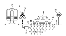
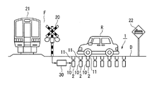
図1及び図2は危険認識装置の概略構成図であって、これらの図において、符号Fは踏切、符合Dは踏切F手前側に位置する路面上の危険認識領域である。
An embodiment of the present invention will be described with reference to FIGS.
1 and 2 are schematic configuration diagrams of the danger recognition device. In these drawings, reference numeral F denotes a crossing, and reference D denotes a danger recognition region on the road surface located on the front side of the crossing F. FIG.
この路面上の危険認識領域Dにはその上面を通過する車両Rに対して危険を報知する危険報知手段1が設けられている。
この危険報知手段1は、列車が接近した場合に、上方又は下方に向けて往復動する可動部2を複数具備している。
The danger recognition area D on the road surface is provided with danger notification means 1 for notifying the vehicle R passing the upper surface of the danger.
The danger notification means 1 includes a plurality of
各可動部2は、駆動源としての油圧シリンダ10と、該油圧シリンダ10のピストン先端に設置された上下動部材11とからなるものであって、図1に示す上方側に向けて突出する「突出位置」と、図2に示す下方側に後退する「退避位置」との間で往復動する。
なお、これら可動部2における「突出位置」と「退避位置」との往復動は、踏切Fに設置された警報機20の作動と連動して行われる。すなわち、符号30で示される制御手段では、列車21が近づいて踏切Fの警報機20が作動したことを条件として、図1及び図2に示されるように、可動部2の上下動部材11を上方又は下方に向けて往復動させるように油圧シリンダ10を駆動する。または、列車21が踏切Fに近づいていることを検出した検出装置から送信された信号の受信を条件として、図1及び図2に示されるように、可動部2の上下動部材11を上方又は下方に向けて往復動させるように油圧シリンダ10を駆動するようにしてもよい。
Each
Note that the reciprocation between the “projection position” and the “retraction position” in the
また、これら可動部2における「突出位置」と「退避位置」との往復動は、車両Rの走行に支障が発生せず、かつ車両Rの運転手に列車21の接近が確実に伝達されるように、前記制御手段30に対して最適となる周期を設定する。例えば、前記制御手段30に対して短い周期で、可動部2の上下動部材11を上下動させることにより、可動部2上に位置する車両Rを激しく振動させ、運転者に対してより確実に注意喚起することも可能となる。
Further, the reciprocating motion between the “projecting position” and the “retracted position” in the
また、危険報知手段1の危険認識領域Dは、車両Rの長さ及び幅に応じて設定される他、踏切Fの交通量に応じても設定される。
また、危険報知手段1は、踏切Fの手前でかつ、該踏切Fを示す道路標識22の後方側に配置されている。これにより、まず、道路標識22によって、運転者に対して踏切Fの存在を視覚的に認識させ、その後、危険報知手段1の可動部2の往復動によって、運転者に対して列車接近の状況を体感的に認識させることができる。
Further, the danger recognition area D of the danger notification means 1 is set not only according to the length and width of the vehicle R but also according to the traffic volume of the crossing F.
Further, the danger notification means 1 is disposed in front of the level crossing F and behind the
以上詳細に説明したように本実施形態に示される危険認識装置によれば、踏切Fの手前に位置する路面上の危険認識領域D上に設けられてその上面を通過する車両Rに対して危険を報知する危険報知手段1を有し、該危険報知手段1は、上方側に向けて突出する「突出位置」と、下方側に後退する「退避位置」との間で往復動する可動部2を複数具備する構成であるので、列車21が接近した場合に、「突出位置」(図1)にて車両Rを地面から持ち上げ、また、「退避位置」(図2)にて持ち上げられた車両Rを地面上に下ろす動作を行わせることができる。
すなわち、前記危険報知手段1の可動部2が、列車接近時に、「突出位置」「退避位置」との間で往復動することにより、その上部に位置する車両Rをガタガタと振動させることができ、このような車両Rの振動によって、車内の運転手がこの踏切Fへの列車接近を確実に認識して、運転者のうっかりミスにより発生するであろう鉄道事故を未然に防止することが可能となる。
As described above in detail, according to the danger recognition device shown in the present embodiment, it is dangerous for the vehicle R that is provided on the danger recognition area D on the road surface before the railroad crossing F and passes through the upper surface thereof. The risk notification means 1 includes a
That is, when the
(変形例1)
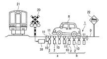
なお、上記実施形態では、図1及び図2に示すように危険報知手段1の複数の可動部2を、列車接近時に、「突出位置」「退避位置」との間で往復動させるとともに、全ての可動部2が「突出位置」又は「退避位置」となるように同一の動きをさせるようにしたが、これに限定されず、図3及び図4に示すように、危険報知手段1の前部領域(範囲aで示す領域)と、後部領域(範囲bで示す領域)とで異なる動きをさせるようにしても良い。
すなわち、図3に示すように、危険報知手段1の前部領域(範囲aで示す領域)内にある可動部2が「退避位置」にあるときに、危険報知手段1の後部領域(範囲bで示す領域)内にある可動部2を「突出位置」とし、また、図4に示すように、危険報知手段1の前部領域(範囲aで示す領域)内にある可動部2が「突出位置」にあるときに、危険報知手段1の後部領域(範囲bで示す領域)内にある可動部2を「退避位置」とし、かつこれら図3と図4の動作を繰り返し行うことにより、可動部2上にある車両Rを前後に揺動させるようにしても良い。
また、このような領域に応じた、可動部2の「突出位置」又は「退避位置」の動作は、前部領域(範囲aで示す領域)又は後部領域(範囲bで示す領域)の区分に限定されず、路面上の危険認識領域D内にて、状況に応じて適宜区分して設定しても良い。
(Modification 1)
In the above embodiment, as shown in FIGS. 1 and 2, the plurality of
That is, as shown in FIG. 3, when the
Further, the operation of the “projection position” or “retraction position” of the
(変形例2)
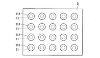
また、上記実施形態では、路面上の危険認識領域D内にて、可動部2の上下動部材11により直接、車両Rを持ち上げるようにしたが、例えば、図5に示すように上下動部材11の上端に、該上下動部材11より大径の円盤状の支持部材11Aを設けても良い。
(Modification 2)
In the above embodiment, the vehicle R is lifted directly by the
(変形例3)
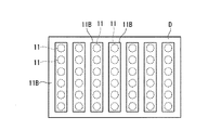
また、上記実施形態では、路面上の危険認識領域D内にて、可動部2の複数の上下動部材11により直接、車両Rを持ち上げるようにしたが、例えば、図6に示すように上下動部材11の上端に道路幅方向に沿う支持部材11Bで連結し、該支持部材11Bを介して、車両Rを持ち上げても良い。このとき、支持部材11Bで連結される複数の上下動部材11は、「突出位置」又は「退避位置」となるように同一の動きをしても良いし、該支持部材11Bがその一端部と他端部で、「突出位置」又は「退避位置」となるような左右の揺動動作を行う設定をしても良い。
(Modification 3)
In the above embodiment, the vehicle R is directly lifted by the plurality of
以上、本発明の実施形態について図面を参照して詳述したが、具体的な構成はこの実施形態に限られるものではなく、本発明の要旨を逸脱しない範囲の設計変更等も含まれる。 As mentioned above, although embodiment of this invention was explained in full detail with reference to drawings, the concrete structure is not restricted to this embodiment, The design change etc. of the range which does not deviate from the summary of this invention are included.
本発明は、踏切を横断しようとする車両に対して、列車が接近している旨の危険状況を確実に認識させることができる踏切危険認識装置に関する。 The present invention relates to a railroad crossing risk recognition device capable of reliably recognizing a danger situation that a train is approaching a vehicle that is going to cross a railroad crossing.
1 危険報知手段
2 可動部
10 油圧シリンダ
11 上下動部材
20 警報機
21 列車
30 制御手段
F 踏切
D 危険認識領域
R 車両
DESCRIPTION OF SYMBOLS 1 Risk alerting | reporting means 2
Claims (4)
前記危険報知手段は、列車が接近した場合に、上方側に向けて突出する突出位置と、下方側に後退する退避位置との間で往復動する可動部を複数具備することを特徴とする踏切危険認識装置。 Having danger notifying means for notifying a vehicle which is provided on the road before the railroad crossing and passes through the upper surface thereof;
The danger notification means comprises a plurality of movable parts that reciprocate between a protruding position protruding upward and a retracted position retracting downward when a train approaches. Danger recognition device.
Priority Applications (1)
| Application Number | Priority Date | Filing Date | Title |
|---|---|---|---|
| JP2011065855A JP2012201156A (en) | 2011-03-24 | 2011-03-24 | Railroad crossing risk recognition system |
Applications Claiming Priority (1)
| Application Number | Priority Date | Filing Date | Title |
|---|---|---|---|
| JP2011065855A JP2012201156A (en) | 2011-03-24 | 2011-03-24 | Railroad crossing risk recognition system |
Publications (1)
| Publication Number | Publication Date |
|---|---|
| JP2012201156A true JP2012201156A (en) | 2012-10-22 |
Family
ID=47182590
Family Applications (1)
| Application Number | Title | Priority Date | Filing Date |
|---|---|---|---|
| JP2011065855A Pending JP2012201156A (en) | 2011-03-24 | 2011-03-24 | Railroad crossing risk recognition system |
Country Status (1)
| Country | Link |
|---|---|
| JP (1) | JP2012201156A (en) |
Citations (2)
| Publication number | Priority date | Publication date | Assignee | Title |
|---|---|---|---|---|
| JPS4927033A (en) * | 1972-07-12 | 1974-03-11 | ||
| JPH11198816A (en) * | 1998-01-12 | 1999-07-27 | Railway Technical Res Inst | Estimate system of visual recognition and method thereof |
-
2011
- 2011-03-24 JP JP2011065855A patent/JP2012201156A/en active Pending
Patent Citations (2)
| Publication number | Priority date | Publication date | Assignee | Title |
|---|---|---|---|---|
| JPS4927033A (en) * | 1972-07-12 | 1974-03-11 | ||
| JPH11198816A (en) * | 1998-01-12 | 1999-07-27 | Railway Technical Res Inst | Estimate system of visual recognition and method thereof |
Similar Documents
| Publication | Publication Date | Title |
|---|---|---|
| CN103208166A (en) | Early warning protection method for danger and intelligent early warning protector for dangerous events for road workers | |
| KR101840329B1 (en) | Danger Avoidance System of Road Worker and Method Thereof | |
| CN101555683A (en) | Efficient low-cost flexible energy dissipation type pier anti-collision safety device | |
| CN110164145A (en) | A kind of high-speed road conditions intelligence warning system and its working method | |
| JP2012201156A (en) | Railroad crossing risk recognition system | |
| CN206162877U (en) | Long -pending waterlogging of road is reported to police to block and is dredged device | |
| CN201406662Y (en) | Flexible energy dissipation pier anti-collision safety device with composite structure | |
| KR20110116929A (en) | Safety device of crosswalk | |
| CN204605667U (en) | A kind of automobile passability detecting device | |
| CN204589855U (en) | A kind of highway height-limiting frame of anti-car crass | |
| KR20110049668A (en) | System and method of alarming proximity of train | |
| CN202925491U (en) | Automatic hydraulic lifting bollard | |
| CN110910676B (en) | Method for preventing bridge from being collided by ship and laser curtain system thereof | |
| CN202563696U (en) | Vehicle-mounted traffic light identification display device | |
| CN101555682B (en) | Flexible energy dissipation type pier anti-collision safety device with composite structure | |
| CN203960785U (en) | Pier anticollision bucket | |
| CN205152825U (en) | Safety warning device is used in road and bridge construction | |
| CN205296000U (en) | Limit for height frame of traffic accident effectively avoiding arousing because of offend | |
| CN202881866U (en) | Roadblock warning device | |
| CN210627513U (en) | Laser curtain system for preventing bridge from being collided by ship | |
| CN209921237U (en) | Large-scale rotating equipment collision device | |
| JP2012185759A (en) | Warning device | |
| CN105297650A (en) | Safe and effective height limiting system | |
| CN203782602U (en) | Road height limit warning device | |
| CN219267110U (en) | Highway emergency safety remote early warning device |
Legal Events
| Date | Code | Title | Description |
|---|---|---|---|
| A621 | Written request for application examination |
Free format text: JAPANESE INTERMEDIATE CODE: A621 Effective date: 20130607 |
|
| A131 | Notification of reasons for refusal |
Free format text: JAPANESE INTERMEDIATE CODE: A131 Effective date: 20140325 |
|
| A02 | Decision of refusal |
Free format text: JAPANESE INTERMEDIATE CODE: A02 Effective date: 20140722 |