JP2012199132A - Electromagnetic relay and contact device - Google Patents
Electromagnetic relay and contact device Download PDFInfo
- Publication number
- JP2012199132A JP2012199132A JP2011063252A JP2011063252A JP2012199132A JP 2012199132 A JP2012199132 A JP 2012199132A JP 2011063252 A JP2011063252 A JP 2011063252A JP 2011063252 A JP2011063252 A JP 2011063252A JP 2012199132 A JP2012199132 A JP 2012199132A
- Authority
- JP
- Japan
- Prior art keywords
- fixed
- contacts
- movable
- contact
- electromagnetic relay
- Prior art date
- Legal status (The legal status is an assumption and is not a legal conclusion. Google has not performed a legal analysis and makes no representation as to the accuracy of the status listed.)
- Granted
Links
Images


Landscapes
- Contacts (AREA)
Abstract
【課題】固定接点と可動接点とが離れている状態における複数の固定接点間の絶縁性能の低下を抑制することができる電磁継電器および接点装置を提供することにある。
【解決手段】電磁継電器は、接点装置2を構成する複数の固定接点24,24および複数の可動接点26,26と、電磁石装置1と、ベースブロック20とを備える。電磁石装置1は、通電状態に応じて複数の可動接点26,26を可動させて複数の固定接点24,24と複数の可動接点26,26とを接離させる。ベースブロック20は、絶縁性の材料で形成され、複数の固定接点24,24および複数の可動接点26,26が収納される。ベースブロック20には、複数の固定接点24,24を包囲する位置の内面に凹凸40が形成されている。
【選択図】図1An object of the present invention is to provide an electromagnetic relay and a contact device capable of suppressing a decrease in insulation performance between a plurality of fixed contacts in a state where the fixed contact and the movable contact are separated from each other.
An electromagnetic relay includes a plurality of fixed contacts and a plurality of movable contacts constituting a contact device, an electromagnet device, and a base block. The electromagnet device 1 moves the plurality of movable contacts 26, 26 according to the energized state to bring the plurality of fixed contacts 24, 24 into contact with and away from the plurality of movable contacts 26, 26. The base block 20 is formed of an insulating material, and stores a plurality of fixed contacts 24 and 24 and a plurality of movable contacts 26 and 26. In the base block 20, irregularities 40 are formed on the inner surface at a position surrounding the plurality of fixed contacts 24, 24.
[Selection] Figure 1
Description
本発明は、電磁石装置の通電状態に応じて固定接点と可動接点とを接離させる電磁継電器および接点装置に関する。 The present invention relates to an electromagnetic relay and a contact device for contacting and separating a fixed contact and a movable contact in accordance with an energized state of an electromagnet device.
従来から、電磁石装置の通電状態に応じて固定接点と可動接点とを接離させる電磁継電器が知られている(例えば特許文献1参照)。特許文献1に記載された電磁継電器は、固定接点と可動接点とが対向して設置されている。固定鉄芯に可動鉄芯が当接した状態では固定接点と可動接点とが当接し、固定鉄芯と可動鉄芯との間に設けられた復帰ばねのばね力によって可動鉄芯が固定鉄芯から離間された状態では固定接点と可動接点とが離れる。
2. Description of the Related Art Conventionally, an electromagnetic relay that contacts and separates a fixed contact and a movable contact according to an energization state of an electromagnet device is known (see, for example, Patent Document 1). In the electromagnetic relay described in
しかしながら、特許文献1に記載された従来の電磁継電器は、高電圧に対応させた場合に、固定接点から可動接点を離すときにケースの内面に沿ってアークが発生しやすくなる。このことが起因となって、従来の電磁継電器では、固定接点と可動接点とが離れている状態における複数の固定接点間の絶縁性能が低下するという問題があった。一例として、従来の電磁継電器では、長期間使用した場合に、固定接点または可動接点の周辺の絶縁性のケースの内面に導電性皮膜が形成されるため、複数の固定接点間の絶縁性能が低下することがある。
However, when the conventional electromagnetic relay described in
本発明は上記の点に鑑みて為され、本発明の目的は、固定接点と可動接点とが離れている状態における複数の固定接点間の絶縁性能の低下を抑制することができる電磁継電器および接点装置を提供することにある。 The present invention has been made in view of the above points, and an object of the present invention is to provide an electromagnetic relay and a contact capable of suppressing a decrease in insulation performance between a plurality of fixed contacts in a state where the fixed contact and the movable contact are separated from each other. To provide an apparatus.
本発明の電磁継電器は、複数の固定接点および複数の可動接点と、通電に応じて前記複数の可動接点を可動させて前記複数の固定接点と前記複数の可動接点とを接離させる電磁石装置と、前記複数の固定接点および前記複数の可動接点が収納されるケースとを備え、前記ケースには、前記複数の固定接点を包囲する位置の内面に凹凸が形成されていることを特徴とする。 An electromagnetic relay according to the present invention includes a plurality of fixed contacts and a plurality of movable contacts, and an electromagnet device that moves the plurality of movable contacts in response to energization to connect and separate the plurality of fixed contacts and the plurality of movable contacts. And a case in which the plurality of fixed contacts and the plurality of movable contacts are accommodated, and the case has irregularities formed on an inner surface at a position surrounding the plurality of fixed contacts.
この電磁継電器において、前記凹凸は、前記ケースの側壁であって前記複数の固定接点間に対向する位置の内面に、前記複数の固定接点と前記複数の可動接点とが接離する方向に沿って形成されていることが好ましい。 In this electromagnetic relay, the unevenness is along a direction in which the plurality of fixed contacts and the plurality of movable contacts are in contact with or separated from the inner surface of the case on the side wall of the case facing the plurality of fixed contacts. Preferably it is formed.
この電磁継電器において、各々が前記固定接点を先端に有し前記ケースの外部に基端を露出して当該ケースに固定された複数の固定端子を備えることが好ましい。 In this electromagnetic relay, it is preferable that each of the electromagnetic relays has a plurality of fixed terminals that are fixed to the case with the fixed contact at the distal end and the base end exposed to the outside of the case.
この電磁継電器において、前記凹凸は、前記ケースにおける前記複数の固定端子の固定面であって当該複数の固定端子間の領域の内面に形成されていることが好ましい。 In this electromagnetic relay, it is preferable that the unevenness is formed on an inner surface of a region between the plurality of fixed terminals, which is a fixed surface of the plurality of fixed terminals in the case.
この電磁継電器において、前記複数の固定端子の各々は、前記先端が前記基端よりも細くなるように形成されていることが好ましい。 In this electromagnetic relay, it is preferable that each of the plurality of fixed terminals is formed so that the distal end is thinner than the proximal end.
この電磁継電器において、前記複数の固定端子の基端間に設けられた絶縁性の仕切り板を備えることが好ましい。 This electromagnetic relay preferably includes an insulating partition plate provided between the base ends of the plurality of fixed terminals.
本発明の電磁継電器は、複数の固定接点および複数の可動接点と、通電に応じて前記複数の可動接点を可動させて前記複数の固定接点と前記複数の可動接点とを接離させる電磁石装置と、前記複数の固定接点および前記複数の可動接点が収納されるケースと、前記固定接点を先端に有し前記ケースの外部に基端を露出して当該ケースに固定された複数の固定端子とを備え、前記複数の固定端子の各々は、先端が基端よりも細いことを特徴とする。 An electromagnetic relay according to the present invention includes a plurality of fixed contacts and a plurality of movable contacts, and an electromagnet device that moves the plurality of movable contacts in response to energization to connect and separate the plurality of fixed contacts and the plurality of movable contacts. A case in which the plurality of fixed contacts and the plurality of movable contacts are housed, and a plurality of fixed terminals that have the fixed contacts at a distal end and have their base ends exposed to the outside of the case and fixed to the case. Each of the plurality of fixed terminals has a distal end narrower than a proximal end.
本発明の電磁継電器は、複数の固定接点および複数の可動接点と、通電に応じて前記複数の可動接点を可動させて前記複数の固定接点と前記複数の可動接点とを接離させる電磁石装置と、前記複数の固定接点および前記複数の可動接点が収納されるケースと、前記固定接点を先端に有し前記ケースの外部に基端を露出して当該ケースに固定された複数の固定端子と、前記複数の固定端子の基端間に設けられた絶縁性の仕切り板とを備えることを特徴とする。 An electromagnetic relay according to the present invention includes a plurality of fixed contacts and a plurality of movable contacts, and an electromagnet device that moves the plurality of movable contacts in response to energization to connect and separate the plurality of fixed contacts and the plurality of movable contacts. A case in which the plurality of fixed contacts and the plurality of movable contacts are housed, a plurality of fixed terminals that are fixed to the case with the fixed contacts at the distal end and a base end exposed outside the case; And an insulating partition plate provided between proximal ends of the plurality of fixed terminals.
本発明の接点装置は、複数の固定接点と、前記複数の固定接点と接離するように可動する複数の可動接点と、前記複数の固定接点および前記複数の可動接点が収納されるケースとを備え、前記ケースには、前記複数の固定接点を包囲する位置の内面に凹凸が形成されていることを特徴とする。 The contact device of the present invention includes a plurality of fixed contacts, a plurality of movable contacts movable so as to be in contact with and separated from the plurality of fixed contacts, and a case in which the plurality of fixed contacts and the plurality of movable contacts are accommodated. The case is characterized in that irregularities are formed on the inner surface at a position surrounding the plurality of fixed contacts.
本発明によれば、固定接点と可動接点とが離れている状態における複数の固定接点間の絶縁性能の低下を抑制することができる。 ADVANTAGE OF THE INVENTION According to this invention, the fall of the insulation performance between several fixed contacts in the state which the fixed contact and the movable contact are separated can be suppressed.
以下の実施形態1〜6では、電磁石装置の通電状態に応じて固定接点と可動接点とを接離させる電磁継電器について説明する。以下の各実施形態の電磁継電器は、さまざまな用途に用いられ、例えば電気自動車などに用いられる。 In the following first to sixth embodiments, electromagnetic relays that connect and separate the fixed contact and the movable contact according to the energization state of the electromagnet device will be described. Electromagnetic relays of the following embodiments are used for various applications, for example, electric vehicles.
(実施形態1)
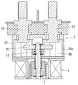
実施形態1に係る電磁継電器は、図1に示すように、励磁用巻線3を有した電磁石装置1と接点装置2とを備えている。以下では、図1の上下左右を上下左右として説明する。
(Embodiment 1)
As shown in FIG. 1, the electromagnetic relay according to the first embodiment includes an
電磁石装置1は、励磁用巻線3を備える固定部材と、固定部材に突き合わされて配置される可動部材とを備えている。固定部材は、励磁用巻線3の他に、合成樹脂製であって励磁用巻線3が巻装された筒状のコイルボビン4と、磁性金属材料からなりコイルボビン4を包囲する継鉄5と、コイルボビン4の内側に配置される固定鉄芯6とを備えている。可動部材は、コイルボビン4の内側において、コイルボビン4の軸方向である上下方向に固定鉄芯6と並んで配置される可動鉄芯7を備えている。固定鉄芯6と可動鉄芯7とは、励磁用巻線3により生じる磁束を通す磁路を継鉄5とともに形成する。コイルボビン4は、励磁用巻線3の上下両側方において上下方向に対向する一対の鍔片8,8を有している。
The
継鉄5は、コイルボビン4の上端面に当接する矩形板状の継鉄上板9と、コイルボビン4の下端面に当接する矩形板状の継鉄下板10と、継鉄上板9および継鉄下板10の左右各端縁同士をそれぞれ連結する一対の継鉄側板11,11とを備えている。継鉄5は、前後方向(図1で紙面に直交する方向)に開放されている。継鉄下板10と一対の継鉄側板11,11とは1枚の板を折曲することにより連続一体に形成されている。
The
固定鉄芯6および可動鉄芯7とコイルボビン4との間には、非磁性材料からなり上面開口の有底円筒状に形成されたプランジャキャップ12が介在する。言い換えると、コイルボビン4の内側に設けられたプランジャキャップ12内に、固定鉄芯6と可動鉄芯7とが収納されることになる。固定鉄芯6はプランジャキャップ12の開口側に配置される。固定鉄芯6および可動鉄芯7はそれぞれ外径がプランジャキャップ12の内径と同程度の円筒状に形成され、可動鉄芯7はプランジャキャップ12の軸方向に移動可能となっている。可動鉄芯7の移動範囲は、固定鉄芯6から離れる初期位置と、固定鉄芯6に当接する当接位置との間に設定されている。固定鉄芯6の内側には、コイルばねからなる復帰ばね13が介在する。復帰ばね13は、可動鉄芯7を初期位置に復帰させる向きのばね力を有している。
Between the fixed
継鉄上板9の中央部には、固定鉄芯6が挿通される挿通孔14が貫通して形成されている。固定鉄芯6は挿通孔14に挿通された状態で継鉄上板9に固定されている。固定鉄芯6を継鉄上板9に固定する構造については後に詳述する。さらに、プランジャキャップ12は、開口周部が継鉄上板9の下面における挿通孔14の周囲に固着されるとともに、下端部が継鉄下板10の中央部に形成された保持孔15内に挿通される。ここで、プランジャキャップ12の下部に収納された可動鉄芯7は、継鉄下板10における保持孔15の周部と磁気結合されることになる。
An
上述した構成によれば、励磁用巻線3への通電時には、固定鉄芯6における可動鉄芯7との対向面と継鉄下板10における保持孔15の周部とは、一対の磁極部として互いに異極性に磁化されることになる。したがって、励磁用巻線3に通電すると、継鉄下板10における保持孔15の周部に磁気結合された可動鉄芯7と固定鉄芯6とが互いに異極性になり、可動鉄芯7は固定鉄芯6に吸引されて当接位置に移動する。一方、励磁用巻線3への通電が停止されると、可動鉄芯7は復帰ばね13により初期位置に復帰する。
According to the configuration described above, when the excitation winding 3 is energized, the opposed surface of the fixed
電磁石装置1の上方には、接点装置2を構成するベースブロック(ケース)20が設けられている。ベースブロック20は、例えばセラミックなどの耐熱性材料により下面が開口する箱状に形成されている。ベースブロック20の上面部21の2箇所には端子孔22,22が形成されている。各端子孔22には、銅系材料から円柱状に形成された固定端子23が挿通されている。各固定端子23の下端面には固定接点24が固着されている。つまり、各固定端子23は、固定接点24を先端231(図1の下端)に有し、ベースブロック20の外部に基端232(図1の上端)を露出してベースブロック20に固定されて設けられている。
A base block (case) 20 constituting the
ベースブロック20内には、2つの固定接点24,24間に跨る形で導電材料からなる平板状の可動接触子25が設けられている。可動接触子25の上面において固定接点24に対向する各部位には、固定接点24とともに接点装置2を構成する可動接点26が設けられている。
In the
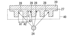
ベースブロック20には、図2に示すように、2つの固定接点24,24を包囲する位置の内面に凹凸40が形成されている。特に、本実施形態では、ベースブロック20において2つの固定接点24,24が並んでいる方向(図2(b)の左右方向)に沿った側壁27の内面に凹凸40が形成されている。つまり、ベースブロック20の側壁27であって2つの固定接点24,24間に対向する位置の内面に凹凸40が形成されている。また、本実施形態では、2つの固定接点24,24が並んでいる方向に直交する方向(図2(b)の上下方向)に沿った側壁27の内面にも凹凸40が形成されている。凹凸40は、2つの固定接点24,24と2つの可動接点26,26(図1参照)とが接離する方向(図2(a)の上下方向)に沿って同じ形状になるように形成されている。なお、図2(b)の上下方向に沿った側壁27の内面には必ずしも凹凸40は形成されていなくてもよい。
As shown in FIG. 2, the
次に、凹凸40の機能について図3を用いて説明する。電磁継電器は使用時間が長くなると、導電性物質の飛散源(図3では固定接点24で表わしている)となる固定接点24または可動接点26(可動接触子25内)から導電性物質が飛散することがある。導電性物質は、例えば金属または炭化物などである。飛散源から飛散した導電性物質は、ベースブロック20の側壁27の内面に付着する。このような場合、本実施形態のように側壁27の内面に凹凸40が形成されていると、飛散源から見て影となる複数の領域28,28,……が形成される。各領域28には、導電性物質が飛散しにくいため、側壁27の内面において導電性物質が付着しづらい部分を設けることができる。つまり、側壁27の内面において絶縁性が低下しづらい領域を設けることができる。これにより、ベースブロック20の側壁27において、導電性物質が2つの固定接点24,24が並んでいる方向(図3の左右方向)に連続して付着しづらくなり、使用初期に対して絶縁性能の大幅な低下を防ぐことができる。
Next, the function of the
上記より、凹凸40の形状は、飛散源(固定接点24、可動接点26)から見て影となる領域28が形成されるような形状に設計されている。具体的には、領域28が形成されるように、凹凸40について凹部の幅A1と凸部の幅A2と深さA3とが定められる。
From the above, the shape of the projections and
続いて、図4を用いてベースブロック20における沿面距離について説明する。図4(a)は、本実施形態の電磁継電器の場合を示し、図4(b)は、凹凸40が形成されていない場合を比較例として示す。図4(a)と図4(b)とを比較すると、図4(a)の矢印の長さのほうが図4(b)の矢印の長さよりも長い。つまり、本実施形態の電磁継電器は、凹凸40が形成されていることによって、凹凸40が形成されていない場合(図4(b)参照)よりも、沿面距離を長くすることができ、絶縁性を高めることができる。
Next, the creepage distance in the
図1に示す可動接触子25の中央部には、軸孔31が貫通して形成されている。軸孔31には、可動接触子25を可動鉄芯7に連結するシャフト30の一端部が挿通されている。シャフト30は、丸棒状に形成された部材であって、可動接触子25から上方に突出した部分により可動接触子25に対して抜け止めがなされている。継鉄上板9と可動接触子25との間には、コイルばねからなる接圧ばね33が設けられ、接圧ばね33には、シャフト30が挿通されている。可動接触子25は、接圧ばね33のばね力によって上方に押し付けられるので、シャフト30の上端部に保持されることになる。シャフト30の下端部は、固定鉄芯6に挿通され、可動鉄芯7に結合される。この構成により、可動接触子25が可動鉄芯7の移動に連動して上下方向に移動する。
A
ここにおいて、可動鉄芯7が初期位置にあるときには可動接点26と固定接点24とが互いに離間され、可動鉄芯7が当接位置にあるときには可動接点26と固定接点24とが接触するように、可動鉄芯7と可動接触子25との位置関係が設定される。要するに、励磁用巻線3に通電していない期間には2つの固定端子23,23間が絶縁され、励磁用巻線3に通電している期間には2つの固定端子23,23間が導通することになる。可動接点26と固定接点24との間の接触圧は接圧ばね33によって確保される。
Here, when the
また、接点装置2と固定鉄芯6と可動鉄芯7とが気密空間に収納されるように、ベースブロック20と継鉄上板9との隙間を覆う筒状の連結体34が設けられている。ベースブロック20と固定端子23と継鉄上板9とプランジャキャップ12と連結体34とを気密接合することにより、ベースブロック20と固定端子23と継鉄上板9とプランジャキャップ12と連結体34とで囲まれた空間は気密空間となる。この気密空間には水素のような消弧性ガスが封入される。
In addition, a cylindrical connecting
以上の説明より、本実施形態の電磁継電器は、ベースブロック(ケース)20の内面に凹凸40が形成されている。これにより、金属または炭化物などの導電性物質が固定接点24または可動接点26からベースブロック20に飛散した場合であっても、ベースブロック20の内面に固定接点24または可動接点26から影となる領域28ができ、領域28には導電性物質が付着しづらくなる。また、ベースブロック20の内面に凹凸40が形成されていることによって、ベースブロック20の内面の沿面距離を長くすることができる。その結果、本実施形態の電磁継電器では、上述の領域28の形成および沿面距離の延長によって、ベースブロック20の内面の絶縁性を維持することができるので、ベースブロック20の内面を介した複数の固定接点24,24間の絶縁不良を防止することができる。つまり、固定接点24と可動接点26とが離れている状態における2つの固定接点24,24間の絶縁性能の低下を抑制することができる。
From the above description, the electromagnetic relay of this embodiment has the
なお、本実施形態の変形例として、図5に示すような固定鉄芯を備えていない電磁継電器においても、本実施形態と同様の凹凸40を形成することができる。
As a modification of the present embodiment, an
(実施形態2)
実施形態2に係る電磁継電器は、図6に示すような構成であり、実施形態1と同様の凹凸40が形成されている。
(Embodiment 2)
The electromagnetic relay according to the second embodiment has a configuration as shown in FIG. 6 and has the
本実施形態の電磁継電器では、電磁石装置1において、励磁用巻線3に通電すると、可動鉄芯7とシャフト30とが電磁力により固定鉄芯6側に吸引される。可動接触子25は、接圧ばね33に付勢されて可動鉄芯7などに追従して下側に移動する。これにより、3つの可動接点26,26,26が3つの固定接点24,24,24に当接する。3つの可動接点26,26,26が3つの固定接点24,24,24に当接した後、さらに可動鉄芯7が下側に移動し、シャフト30側から可動接触子25が離れる。
In the electromagnetic relay of this embodiment, when the exciting winding 3 is energized in the
一方、励磁用巻線3への通電が遮断されると、復帰ばね13により可動鉄芯7および可動接触子25が固定鉄芯6の反対側(図6(a)の上側)に付勢される。これにより、3つの可動接点26,26,26が3つの固定接点24,24,24から離れる。
On the other hand, when the energization of the exciting winding 3 is cut off, the
上記のように動作する電磁継電器は、3つの固定接点24,24,24および3つの可動接点26,26,26が収納される絶縁性のケース20aが設けられている。ケース20aには、3つの固定接点24,24,24を包囲する位置の内面に凹凸40が形成されている。具体的には、凹凸40は、ケース20aの側壁27の全ての内面(3つの固定接点24,24,24間に対向する位置の内面を含む)に、3つの固定接点24,24,24と3つの可動接点26,26,26とが接離する方向(図6(a)の上下方向)に沿って同じ形状になるように形成されている。なお、3つの固定接点24,24,24と3つの可動接点26,26,26とケース20aは接点装置2を構成する部材である。
The electromagnetic relay operating as described above is provided with an insulating
本実施形態の電磁継電器においても、導電性物質が固定接点24または可動接点26からケース20aに飛散した場合であっても、ケース20aの凹凸40によって、ケース20aの内面に固定接点24または可動接点26から影となる領域ができ、領域28には導電性物質が付着しづらくなる。また、ベースブロック20の内面に凹凸40が形成されていることによって、ベースブロック20の内面の沿面距離を長くすることができる。その結果、本実施形態の電磁継電器では、上述の領域28の形成および沿面距離の延長によって、ケース20aの内面の絶縁性を維持することができるので、ケース20aの内面を介した3つの固定接点24,24,24間の絶縁不良を防止することができる。つまり、固定接点24と可動接点26とが離れている状態における2つの固定接点24,24間の絶縁性能の低下を抑制することができる。
Even in the electromagnetic relay of the present embodiment, even when the conductive material is scattered from the fixed
(実施形態3)
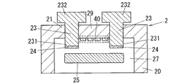
実施形態3に係る電磁継電器は、図7に示すように、ベースブロック20の上面部21に凹凸40が形成されている。なお、実施形態1の電磁継電器(図1,2参照)と同様の構成要素については、同一の符号を付して説明を省略する。
(Embodiment 3)
As shown in FIG. 7, the electromagnetic relay according to the third embodiment has
本実施形態の凹凸40は、ベースブロック20における2つの固定端子23,23が固定されている上面部21であって2つの固定端子23,23間の領域29の内面に形成されている。
The
本実施形態の電磁継電器によれば、最も高い電圧がかかる2つの固定端子23,23間の沿面距離を伸ばすことができるので、絶縁不良を防止するとともに、絶縁耐圧を向上させることができる。これにより、固定接点24と可動接点26(図1参照)とが離れている状態における2つの固定接点24,24間の絶縁性能の低下を抑制することができる。
According to the electromagnetic relay of this embodiment, the creeping distance between the two fixed
なお、本実施形態のように凹凸40が形成されている構造は、実施形態1,2の電磁継電器に適用してもよい。つまり、ベースブロック20の上面部21の内面にも側壁27の内面にも凹凸40が形成されていてもよい。
In addition, you may apply the structure in which the unevenness |
(実施形態4)
実施形態4に係る電磁継電器は、図8に示すよう形状の2つの固定端子23,23を備えている点で、実施形態1に係る電磁継電器(図2参照)と相違する。なお、実施形態1の電磁継電器と同様の構成要素については、同一の符号を付して説明を省略する。
(Embodiment 4)
The electromagnetic relay according to the fourth embodiment is different from the electromagnetic relay according to the first embodiment (see FIG. 2) in that it includes two fixed
本実施形態の各固定端子23は、先端231が基端232よりも細くなるように形成されている。つまり、本実施形態の各固定端子23では、先端231と基端232とが同心軸上の円柱であり、断面円の半径について先端231のほうが基端232よりも短い。なお、実施形態1の各固定端子23(図2参照)と同様の機能については説明を省略する。
Each fixed
本実施形態の電磁継電器によれば、固定端子の先端と基端とが同じ場合よりも、2つの固定端子23,23の基端232,232間の距離L1を広げることができるので、高電圧が印加されたときの放電による短絡を防止することができる。また、各固定端子23の先端231が細くなるように形成されていることによって、各固定端子23の先端231とベースブロック20の内面との距離L2を確保することができるので、最大アーク長を維持することができる。これにより、固定接点24と可動接点26(図1参照)とが離れている状態における2つの固定接点24,24間の絶縁性能の低下を抑制することができる。
According to the electromagnetic relay of this embodiment, the distance L1 between the base ends 232 and 232 of the two fixed
なお、本実施形態の固定端子23の形状は、実施形態1〜3の電磁継電器に適用してもよい。
In addition, you may apply the shape of the fixed
(実施形態5)
実施形態5に係る電磁継電器は、図9に示すような形状の2つの固定端子23,23を備えている点で、実施形態4に係る電磁継電器(図8参照)と相違する。なお、実施形態4の電磁継電器と同様の構成要素については、同一の符号を付して説明を省略する。
(Embodiment 5)
The electromagnetic relay according to the fifth embodiment is different from the electromagnetic relay according to the fourth embodiment (see FIG. 8) in that it includes two fixed
本実施形態の各固定端子23の先端231は、図9(b)に示すように、円柱の一部が切り欠きされた形状である。なお、実施形態4の各固定端子23(図8参照)と同様の機能については説明を省略する。
As shown in FIG. 9B, the
本実施形態の電磁継電器においても、固定端子の先端と基端とが同じ場合よりも、2つの固定端子23,23の基端232,232間の距離L1を広げることができるので、高電圧が印加されたときの放電による短絡を防止することができる。また、各固定端子23の先端231が細くなるように形成されていることによって、各固定端子23の先端231とベースブロック20の内面との距離L2を確保することができるので、最大アーク長を維持することができる。これにより、固定接点24と可動接点26(図1参照)とが離れている状態における2つの固定接点24,24間の絶縁性能の低下を抑制することができる。
Also in the electromagnetic relay of this embodiment, since the distance L1 between the base ends 232 and 232 of the two fixed
なお、本実施形態の固定端子23の形状は、実施形態1〜3の電磁継電器(ベースブロック20の内面に凹凸40が形成された構成の電磁継電器)に適用してもよい。
In addition, you may apply the shape of the fixed
(実施形態6)
実施形態6に係る電磁継電器は、図10に示すような仕切り板50を備えている点で、実施形態1に係る電磁継電器(図1参照)と相違する。なお、実施形態1の電磁継電器と同様の構成要素については、同一の符号を付して説明を省略する。
(Embodiment 6)
The electromagnetic relay according to the sixth embodiment is different from the electromagnetic relay according to the first embodiment (see FIG. 1) in that a
仕切り板50は、例えばセラミックまたは樹脂などの絶縁性の材料で平板状に形成され、ベースブロック20とは別部材としてベースブロック20の上面部21上に設置されている。具体的には、仕切り板50は、ベースブロック20の上面部21の外部側において2つの固定端子23,23の基端232,232間に設けられている。
The
本実施形態の電磁継電器は、絶縁性の仕切り板50を2つの固定端子23,23の基端232,232間に備えていることによって、2つの固定端子23,23間に高電圧が印加された場合に、放電による短絡を防止することができる。つまり、固定接点24と可動接点26(図1参照)とが離れている状態における2つの固定接点24,24間の絶縁性能の低下を抑制することができる。
In the electromagnetic relay according to the present embodiment, an insulating
なお、本実施形態の仕切り板50は、実施形態1〜3の電磁継電器(ベースブロック20の内面に凹凸40が形成された構成の電磁継電器)または実施形態4,5の電磁継電器に備えてもよい。
In addition, the
1 電磁石装置
2 接点装置
20 ベースブロック(ケース)
20a ケース
21 上面部
23 固定端子
231 先端
232 基端
24 固定接点
26 可動接点
27 側壁
40 凹凸
50 仕切り板
1
Claims (9)
通電に応じて前記複数の可動接点を可動させて前記複数の固定接点と前記複数の可動接点とを接離させる電磁石装置と、
前記複数の固定接点および前記複数の可動接点が収納されるケースとを備え、
前記ケースには、前記複数の固定接点を包囲する位置の内面に凹凸が形成されている
ことを特徴とする電磁継電器。 A plurality of fixed contacts and a plurality of movable contacts;
An electromagnet device that moves the plurality of movable contacts in response to energization and separates the plurality of fixed contacts and the plurality of movable contacts;
A case in which the plurality of fixed contacts and the plurality of movable contacts are stored;
The case is provided with irregularities on the inner surface at a position surrounding the plurality of fixed contacts.
通電に応じて前記複数の可動接点を可動させて前記複数の固定接点と前記複数の可動接点とを接離させる電磁石装置と、
前記複数の固定接点および前記複数の可動接点が収納されるケースと、
前記固定接点を先端に有し前記ケースの外部に基端を露出して当該ケースに固定された複数の固定端子とを備え、
前記複数の固定端子の各々は、先端が基端よりも細い
ことを特徴とする電磁継電器。 A plurality of fixed contacts and a plurality of movable contacts;
An electromagnet device that moves the plurality of movable contacts in response to energization and separates the plurality of fixed contacts and the plurality of movable contacts;
A case in which the plurality of fixed contacts and the plurality of movable contacts are stored;
A plurality of fixed terminals fixed to the case by exposing the base end to the outside of the case having the fixed contact at the tip;
Each of the plurality of fixed terminals has a tip that is thinner than a base end.
通電に応じて前記複数の可動接点を可動させて前記複数の固定接点と前記複数の可動接点とを接離させる電磁石装置と、
前記複数の固定接点および前記複数の可動接点が収納されるケースと、
前記固定接点を先端に有し前記ケースの外部に基端を露出して当該ケースに固定された複数の固定端子と、
前記複数の固定端子の基端間に設けられた絶縁性の仕切り板と
を備えることを特徴とする電磁継電器。 A plurality of fixed contacts and a plurality of movable contacts;
An electromagnet device that moves the plurality of movable contacts in response to energization and separates the plurality of fixed contacts and the plurality of movable contacts;
A case in which the plurality of fixed contacts and the plurality of movable contacts are stored;
A plurality of fixed terminals fixed to the case with the fixed contact at the tip and exposing the base end to the outside of the case;
An electromagnetic relay comprising: an insulating partition plate provided between base ends of the plurality of fixed terminals.
前記複数の固定接点と接離するように可動する複数の可動接点と、
前記複数の固定接点および前記複数の可動接点が収納されるケースとを備え、
前記ケースには、前記複数の固定接点を包囲する位置の内面に凹凸が形成されている
ことを特徴とする接点装置。 Multiple fixed contacts;
A plurality of movable contacts movable so as to be in contact with and separated from the plurality of fixed contacts;
A case in which the plurality of fixed contacts and the plurality of movable contacts are stored;
The contact device is characterized in that irregularities are formed on the inner surface of the case surrounding the plurality of fixed contacts.
Priority Applications (1)
| Application Number | Priority Date | Filing Date | Title |
|---|---|---|---|
| JP2011063252A JP5763941B2 (en) | 2011-03-22 | 2011-03-22 | Electromagnetic relay and contact device |
Applications Claiming Priority (1)
| Application Number | Priority Date | Filing Date | Title |
|---|---|---|---|
| JP2011063252A JP5763941B2 (en) | 2011-03-22 | 2011-03-22 | Electromagnetic relay and contact device |
Publications (2)
| Publication Number | Publication Date |
|---|---|
| JP2012199132A true JP2012199132A (en) | 2012-10-18 |
| JP5763941B2 JP5763941B2 (en) | 2015-08-12 |
Family
ID=47181152
Family Applications (1)
| Application Number | Title | Priority Date | Filing Date |
|---|---|---|---|
| JP2011063252A Expired - Fee Related JP5763941B2 (en) | 2011-03-22 | 2011-03-22 | Electromagnetic relay and contact device |
Country Status (1)
| Country | Link |
|---|---|
| JP (1) | JP5763941B2 (en) |
Cited By (3)
| Publication number | Priority date | Publication date | Assignee | Title |
|---|---|---|---|---|
| WO2019031588A1 (en) * | 2017-08-10 | 2019-02-14 | オムロン株式会社 | Connection unit |
| CN112041961A (en) * | 2018-04-19 | 2020-12-04 | Tdk电子股份有限公司 | Switching device |
| CN112582210A (en) * | 2019-09-30 | 2021-03-30 | 欧姆龙株式会社 | Relay with a movable contact |
Citations (4)
| Publication number | Priority date | Publication date | Assignee | Title |
|---|---|---|---|---|
| JPH11204011A (en) * | 1998-01-08 | 1999-07-30 | Omron Corp | Electromagnetic relay |
| JP2001118450A (en) * | 1999-10-14 | 2001-04-27 | Matsushita Electric Works Ltd | Contact device |
| JP2007207494A (en) * | 2006-01-31 | 2007-08-16 | Mitsuba Corp | Electromagnetic relay |
| JP2007287525A (en) * | 2006-04-18 | 2007-11-01 | Matsushita Electric Works Ltd | Electromagnetic switching device |
-
2011
- 2011-03-22 JP JP2011063252A patent/JP5763941B2/en not_active Expired - Fee Related
Patent Citations (4)
| Publication number | Priority date | Publication date | Assignee | Title |
|---|---|---|---|---|
| JPH11204011A (en) * | 1998-01-08 | 1999-07-30 | Omron Corp | Electromagnetic relay |
| JP2001118450A (en) * | 1999-10-14 | 2001-04-27 | Matsushita Electric Works Ltd | Contact device |
| JP2007207494A (en) * | 2006-01-31 | 2007-08-16 | Mitsuba Corp | Electromagnetic relay |
| JP2007287525A (en) * | 2006-04-18 | 2007-11-01 | Matsushita Electric Works Ltd | Electromagnetic switching device |
Cited By (13)
| Publication number | Priority date | Publication date | Assignee | Title |
|---|---|---|---|---|
| CN110612589B (en) * | 2017-08-10 | 2022-11-11 | 欧姆龙株式会社 | connection unit |
| JP2019036434A (en) * | 2017-08-10 | 2019-03-07 | オムロン株式会社 | Connection unit |
| CN110612589A (en) * | 2017-08-10 | 2019-12-24 | 欧姆龙株式会社 | connection unit |
| US11244798B2 (en) | 2017-08-10 | 2022-02-08 | Omron Corporation | Connection unit |
| WO2019031588A1 (en) * | 2017-08-10 | 2019-02-14 | オムロン株式会社 | Connection unit |
| CN112041961A (en) * | 2018-04-19 | 2020-12-04 | Tdk电子股份有限公司 | Switching device |
| JP2021518043A (en) * | 2018-04-19 | 2021-07-29 | テーデーカー エレクトロニクス アーゲー | Switching device |
| JP7136918B2 (en) | 2018-04-19 | 2022-09-13 | テーデーカー エレクトロニクス アーゲー | switching device |
| US11462379B2 (en) | 2018-04-19 | 2022-10-04 | Tdk Electronics Ag | Switching device with two stationary contacts and a movable contact in a switching chamber |
| CN112041961B (en) * | 2018-04-19 | 2023-08-22 | Tdk电子股份有限公司 | switchgear |
| US11854757B2 (en) | 2018-04-19 | 2023-12-26 | Tdk Electronics Ag | Switching device with two stationary contacts and a movable contact in a switching chamber |
| JP7467552B2 (en) | 2018-04-19 | 2024-04-15 | テーデーカー エレクトロニクス アーゲー | Switching Devices |
| CN112582210A (en) * | 2019-09-30 | 2021-03-30 | 欧姆龙株式会社 | Relay with a movable contact |
Also Published As
| Publication number | Publication date |
|---|---|
| JP5763941B2 (en) | 2015-08-12 |
Similar Documents
| Publication | Publication Date | Title |
|---|---|---|
| CN104412353B (en) | Contact making device and the electromagnetic relay being equipped with this contact making device | |
| CN102668005B (en) | Electromagnetic switch | |
| CN110400724B (en) | Electromagnetic Relay | |
| US20100207713A1 (en) | Electromagnetic relay | |
| JP2016201286A (en) | Contact device and electromagnetic relay | |
| KR200488063Y1 (en) | Relay | |
| JP2012199117A (en) | Contact device and electromagnetic switching device using the same | |
| JP6168785B2 (en) | Polarized electromagnetic relay | |
| JP5120162B2 (en) | Electromagnetic relay | |
| JP2012199126A (en) | Contact device and electromagnetic switching device using the same | |
| JP5763941B2 (en) | Electromagnetic relay and contact device | |
| JP5151829B2 (en) | Polarized electromagnet, electromagnetic contactor, electromagnetic switch, and manufacturing method of polarized electromagnet | |
| US20150228431A1 (en) | Electromagnetic relay | |
| JP2020074333A (en) | Electromagnetic relay | |
| JP2009199894A (en) | Electromagnetic relay | |
| US6731191B2 (en) | DC electromagnet | |
| JP2001118450A (en) | Contact device | |
| JP2012212668A (en) | Contact point device and electromagnetic switch | |
| JP4645663B2 (en) | relay | |
| JP4458090B2 (en) | Electromagnet device | |
| JP2014112482A (en) | Electromagnetic contactor | |
| JP7357193B2 (en) | electromagnetic relay | |
| JP7120057B2 (en) | electromagnet device | |
| JP2022139817A (en) | electromagnetic relay | |
| JP2006310251A (en) | Conductive bar for relay and its manufacturing method |
Legal Events
| Date | Code | Title | Description |
|---|---|---|---|
| A621 | Written request for application examination |
Free format text: JAPANESE INTERMEDIATE CODE: A621 Effective date: 20140319 |
|
| A711 | Notification of change in applicant |
Free format text: JAPANESE INTERMEDIATE CODE: A711 Effective date: 20141008 |
|
| A977 | Report on retrieval |
Free format text: JAPANESE INTERMEDIATE CODE: A971007 Effective date: 20141203 |
|
| A131 | Notification of reasons for refusal |
Free format text: JAPANESE INTERMEDIATE CODE: A131 Effective date: 20141209 |
|
| A521 | Written amendment |
Free format text: JAPANESE INTERMEDIATE CODE: A523 Effective date: 20150209 |
|
| TRDD | Decision of grant or rejection written | ||
| A01 | Written decision to grant a patent or to grant a registration (utility model) |
Free format text: JAPANESE INTERMEDIATE CODE: A01 Effective date: 20150519 |
|
| A61 | First payment of annual fees (during grant procedure) |
Free format text: JAPANESE INTERMEDIATE CODE: A61 Effective date: 20150612 |
|
| LAPS | Cancellation because of no payment of annual fees |