JP2012196105A - Inter-vehicle charging device - Google Patents
Inter-vehicle charging device Download PDFInfo
- Publication number
- JP2012196105A JP2012196105A JP2011060081A JP2011060081A JP2012196105A JP 2012196105 A JP2012196105 A JP 2012196105A JP 2011060081 A JP2011060081 A JP 2011060081A JP 2011060081 A JP2011060081 A JP 2011060081A JP 2012196105 A JP2012196105 A JP 2012196105A
- Authority
- JP
- Japan
- Prior art keywords
- vehicle
- battery
- charging
- rescue
- target vehicle
- Prior art date
- Legal status (The legal status is an assumption and is not a legal conclusion. Google has not performed a legal analysis and makes no representation as to the accuracy of the status listed.)
- Granted
Links
Images


Classifications
-
- Y—GENERAL TAGGING OF NEW TECHNOLOGICAL DEVELOPMENTS; GENERAL TAGGING OF CROSS-SECTIONAL TECHNOLOGIES SPANNING OVER SEVERAL SECTIONS OF THE IPC; TECHNICAL SUBJECTS COVERED BY FORMER USPC CROSS-REFERENCE ART COLLECTIONS [XRACs] AND DIGESTS
- Y02—TECHNOLOGIES OR APPLICATIONS FOR MITIGATION OR ADAPTATION AGAINST CLIMATE CHANGE
- Y02E—REDUCTION OF GREENHOUSE GAS [GHG] EMISSIONS, RELATED TO ENERGY GENERATION, TRANSMISSION OR DISTRIBUTION
- Y02E60/00—Enabling technologies; Technologies with a potential or indirect contribution to GHG emissions mitigation
- Y02E60/10—Energy storage using batteries
-
- Y—GENERAL TAGGING OF NEW TECHNOLOGICAL DEVELOPMENTS; GENERAL TAGGING OF CROSS-SECTIONAL TECHNOLOGIES SPANNING OVER SEVERAL SECTIONS OF THE IPC; TECHNICAL SUBJECTS COVERED BY FORMER USPC CROSS-REFERENCE ART COLLECTIONS [XRACs] AND DIGESTS
- Y02—TECHNOLOGIES OR APPLICATIONS FOR MITIGATION OR ADAPTATION AGAINST CLIMATE CHANGE
- Y02T—CLIMATE CHANGE MITIGATION TECHNOLOGIES RELATED TO TRANSPORTATION
- Y02T10/00—Road transport of goods or passengers
- Y02T10/60—Other road transportation technologies with climate change mitigation effect
- Y02T10/70—Energy storage systems for electromobility, e.g. batteries
-
- Y—GENERAL TAGGING OF NEW TECHNOLOGICAL DEVELOPMENTS; GENERAL TAGGING OF CROSS-SECTIONAL TECHNOLOGIES SPANNING OVER SEVERAL SECTIONS OF THE IPC; TECHNICAL SUBJECTS COVERED BY FORMER USPC CROSS-REFERENCE ART COLLECTIONS [XRACs] AND DIGESTS
- Y02—TECHNOLOGIES OR APPLICATIONS FOR MITIGATION OR ADAPTATION AGAINST CLIMATE CHANGE
- Y02T—CLIMATE CHANGE MITIGATION TECHNOLOGIES RELATED TO TRANSPORTATION
- Y02T10/00—Road transport of goods or passengers
- Y02T10/60—Other road transportation technologies with climate change mitigation effect
- Y02T10/72—Electric energy management in electromobility
Abstract
Description
本発明は、例えば、電気自動車やハイブリッド自動車等の車両に搭載されて他の車両のバッテリーを充電する車両間充電装置に関するものである。 The present invention relates to an inter-vehicle charging device that is mounted on a vehicle such as an electric vehicle or a hybrid vehicle and charges a battery of another vehicle.
いわゆるバッテリー上がりで自走できなくなった電気自動車等の車両(以下、救援対象車両という)を、バッテリー残量が十分にある電気自動車またはハイブリッド自動車等の車両(以下、救援車両という)により救援するため、車両間で充放電する従来技術として、特許文献1に記載された発明がある。
To rescue a vehicle such as an electric vehicle (hereinafter referred to as a vehicle to be rescued) that has become unable to run on its own due to a so-called battery run out by a vehicle such as an electric vehicle or a hybrid vehicle (hereinafter referred to as a rescue vehicle) having a sufficient remaining battery level. As a conventional technique for charging and discharging between vehicles, there is an invention described in
上記従来技術を、以下に説明する。
図19は、自車のバッテリー残量が十分にある救援車両101が、バッテリーの切れた救援対象車両102を充電する主回路構成を示している。
まず、両車のバッテリーBAT1,BAT2を接続する際に発生する突入電流を抑制するため、ケーブル5を接続した後リレーRY2a,RY3aとRY2b,RY3bとをそれぞれ導通させ、突入電流防止抵抗1を利用して予備充電を開始する。その後、リレーRY1a,RY1bを導通させてバッテリーBAT1からバッテリーBAT2への主充電が開始される。なお、11はコネクタである。
The above prior art will be described below.
FIG. 19 shows a main circuit configuration in which the
First, in order to suppress the inrush current generated when the batteries BAT 1 and BAT 2 of both vehicles are connected, after the
また、車両外部へ電力を供給する従来技術としては、特許文献2に記載された発明がある。
この従来技術は、内燃機関と、星形結線された第1の多相巻線を固定子巻線として含む第1の回転電機と、からなる発電装置を備えており、第1の回転電機は、内燃機関のクランク軸に回転軸が結合され、内燃機関の出力を用いて発電する。また、星形結線された第2の多相巻線を固定子巻線として含む第2の回転電機と、第1,第2の回転電機にそれぞれ対応して設けられる第1,第2のインバータと、電気負荷へ電力を出力するための電圧差を第1の多相巻線の第1の中性点と第2の多相巻線の第2の中性点との間に発生するように第1,第2のインバータを制御するインバータ制御部と、第1,第2の中性点に接続され、第1,第2の中性点から電気負荷へ電力を出力するための電力出力部と、を有する電力変換部を備えている。
前記制御部は、第1の回転電機の発電量が電力変換部から外部の電気負荷へ出力される電力量とほぼ同等となるように、第1の回転電機の発電量を制御するものである。
Further, as a conventional technique for supplying electric power to the outside of the vehicle, there is an invention described in
This prior art includes a power generation device that includes an internal combustion engine and a first rotating electrical machine that includes a star-connected first multiphase winding as a stator winding, and the first rotating electrical machine includes: The rotating shaft is coupled to the crankshaft of the internal combustion engine, and power is generated using the output of the internal combustion engine. Also, a second rotating electric machine including the second multiphase winding connected in a star shape as a stator winding, and first and second inverters provided corresponding to the first and second rotating electric machines, respectively. And a voltage difference for outputting power to the electric load is generated between the first neutral point of the first multiphase winding and the second neutral point of the second multiphase winding. And an inverter control unit for controlling the first and second inverters, and a power output connected to the first and second neutral points to output power from the first and second neutral points to the electric load. And a power conversion unit having the unit.
The control unit controls the power generation amount of the first rotating electrical machine so that the power generation amount of the first rotating electrical machine is substantially equal to the power amount output from the power conversion unit to the external electric load. .
特許文献1に係る従来技術では、充電時の突入電流を抑えるためにプリチャージ回路が必要であり、コストや占有スペースが増大する。また、充電電流は救援車両と救援対象車両のバッテリー仕様、更には、バッテリーのSOC(充電状態)やSOH(劣化状態)に依存しており、適切なプリチャージ抵抗値や充電電流許容値を超えないようなメインリレーの投入タイミングを予め知ることは困難である。つまり、異なる車種間では、この従来技術を適用できない懸念がある。
更に、この従来技術では充電量を制御できないため、救援対象車両が最寄りの充電ステーションまで自走するのに必要最低限な充電量を充電する、といった運用ができない。
In the prior art according to
Furthermore, since the amount of charge cannot be controlled with this conventional technology, an operation such as charging the minimum amount of charge necessary for the vehicle to be rescued to travel to the nearest charging station cannot be performed.
また、特許文献2に係る従来技術では、電力変換器を別途追加することなく外部負荷に供給する電流を制御することが可能であるが、2組の回転電機(モータ)及びインバータが必要になり、コストの増大や装置の大型化を招く。
一方、他の手段としては、標準規格に準拠する急速充電器を搭載した救援車両を使用することが考えられる。しかしながら、これによると急速充電用のDC/DCコンバータが別途必要になり、コスト高やスペースの圧迫を招く等の問題がある。
Moreover, in the prior art which concerns on
On the other hand, as another means, it is possible to use a rescue vehicle equipped with a quick charger that complies with the standard. However, this requires a separate DC / DC converter for rapid charging, which causes problems such as high cost and space pressure.
そこで、本発明の解決課題は、プリチャージ回路や急速充電用のDC/DCコンバータ等を用いず、救援対象車両のバッテリーに適した充電電流を供給可能であると共に、低コストかつ小型化が可能な車両間充電装置を提供することにある。 Therefore, the problem to be solved by the present invention is that it is possible to supply a charging current suitable for the battery of the vehicle to be rescued without using a precharge circuit or a DC / DC converter for rapid charging, and it is possible to reduce the cost and size. It is providing the vehicle-to-vehicle charging device.
上記課題を解決するため、請求項1に係る発明は、バッテリーと、前記バッテリーの直流電圧を交流電圧に変換するインバータと、前記インバータにより駆動される車両駆動用のモータと、前記バッテリーの管理機能,前記インバータの制御機能,他の救援対象車両のバッテリーへの充電制御機能を備えた制御装置と、を備えた救援車両により、前記救援対象車両のバッテリーを充電可能とした車両間充電装置において、
前記モータの中性点と前記インバータの正負直流母線の一方とから出力される充電電流を前記救援対象車両のバッテリーに供給し、かつ、前記救援対象車両のバッテリーに充電するための制御信号を前記制御装置と前記救援対象車両との間で送受信する接続部を備えたものである。
In order to solve the above problems, an invention according to
Supplying a charging current output from the neutral point of the motor and one of the positive and negative DC buses of the inverter to the battery of the rescue target vehicle, and a control signal for charging the battery of the rescue target vehicle A connection unit that transmits and receives between the control device and the rescue target vehicle is provided.
請求項2に係る発明は、バッテリーと、前記バッテリーの直流電圧を昇圧するコンバータと、前記コンバータの直流出力電圧を交流電圧に変換するインバータと、前記インバータにより駆動される車両駆動用のモータと、前記バッテリーの管理機能,前記コンバータ及び前記インバータの制御機能,他の救援対象車両のバッテリーへの充電制御機能を備えた制御装置と、を備えた救援車両により、前記救援対象車両のバッテリーを充電可能とした車両間充電装置において、
前記モータの中性点と前記インバータの正負直流母線の一方とから出力される充電電流を前記救援対象車両のバッテリーに供給し、かつ、前記救援対象車両のバッテリーに充電するための制御信号を前記制御装置と前記救援対象車両との間で送受信する接続部を備えたものである。
The invention according to
Supplying a charging current output from the neutral point of the motor and one of the positive and negative DC buses of the inverter to the battery of the rescue target vehicle, and a control signal for charging the battery of the rescue target vehicle A connection unit that transmits and receives between the control device and the rescue target vehicle is provided.
請求項3に係る発明は、請求項1または請求項2に記載した車両間充電装置において、前記救援車両は、エンジンと、前記エンジンにより駆動される発電機とを備え、かつ、前記発電機により前記救援車両のバッテリーを充電する充電制御機能を有するものである。
The invention according to
請求項4に係る発明は、請求項1〜請求項3のいずれか1項に記載した車両間充電装置において、前記救援車両は、前記救援対象車両のバッテリーに対する充電量を指定する機能を備えたものである。 According to a fourth aspect of the present invention, in the inter-vehicle charging device according to any one of the first to third aspects, the rescue vehicle has a function of specifying a charge amount for the battery of the rescue target vehicle. Is.
請求項5に係る発明は、請求項1〜請求項4のいずれか1項に記載した車両間充電装置において、前記接続部が、標準化された急速充電用のコネクタを有するものである。 According to a fifth aspect of the present invention, in the inter-vehicle charging apparatus according to any one of the first to fourth aspects, the connecting portion has a standardized quick charging connector.
請求項1に係る発明によれば、救援対象車両のバッテリーに対する充電回路を救援車両のモータ駆動回路と共用して充電電流を任意に制御することができる。これにより、プリチャージ回路を用いずに充電開始時の突入電流を抑えることができ、充電対象である救援対象車両のバッテリーに適した充電電流による充電が可能である。また、これらの機能を実現するために従来、別途に必要であった充電専用のDC/DCコンバータも不要になる。
従って、本発明によれば、小型かつ低コストにて急速充電器相当の充電機能を有する救援車両を提供することができる。
請求項2に係る発明によれば、請求項1の効果に加え、救援対象車両が必要とする充電電圧が救援車両のバッテリー電圧より高い場合にも充電が可能である。
請求項3に係る発明によれば、請求項1,2の効果に加え、エンジンによる発電により救援車両自身のバッテリーを充電することができる。このため、救援車両の航続距離の制約が緩和され、運用範囲を広げることができる。
請求項4に係る発明によれば、救援対象車両が最寄りの充電ステーションまで自走するのに必要最低限な充電量を指定して充電する等の柔軟な対応が可能になる。このため、短時間で応急的な充電が可能であることから救援時間を短くでき、救援車両の効率的な運用を行うことができる。
請求項5に係る発明によれば、標準化されたインターフェースを利用することができ、救援対象車両の車種を問わずに救援することができる。
According to the invention which concerns on
Therefore, according to the present invention, it is possible to provide a rescue vehicle having a charging function equivalent to a quick charger at a small size and at low cost.
According to the second aspect of the invention, in addition to the effect of the first aspect, charging is possible even when the charging voltage required by the rescue target vehicle is higher than the battery voltage of the rescue vehicle.
According to the invention of
According to the invention which concerns on
According to the invention which concerns on
以下、図に沿って本発明の実施形態を説明する。
まず、図4は、本発明の第1実施形態が適用される電気自動車駆動システムの構成図である。このシステムは、電気自動車やハイブリッド自動車を救援車両として他の救援対象車両(電気自動車等)のバッテリーを充電するためのものである。
Hereinafter, embodiments of the present invention will be described with reference to the drawings.
First, FIG. 4 is a configuration diagram of an electric vehicle drive system to which the first embodiment of the present invention is applied. This system is for charging a battery of another rescue target vehicle (electric vehicle or the like) using an electric vehicle or a hybrid vehicle as a rescue vehicle.
図4において、電気自動車駆動システムは、電気自動車を走行させるための永久磁石同期電動機等のモータM1、このモータM1を駆動する3相インバータINV、バッテリーBAT1、制御装置CONT1を備えている。また、1は突入電流防止用の抵抗器、2a,2b,2c,RY1,RY2はリレー、3はコンデンサ、4sは接続部としての標準化された急速充電用のコネクタ、7,7u,7v,7wは電流検出器、8,8aは電圧検出器、10は磁極位置検出器、T11〜T16は半導体スイッチング素子である。
一方、制御装置CONT1は、バッテリー管理装置100、インバータ制御装置300、充電制御装置400、上位制御装置500を備えており、上位制御装置500には外部の充電量設定器200から救援対象車両の充電量設定値(目標充電量)が入力されている。
4, the electric vehicle drive system includes a motor M 1 such as a permanent magnet synchronous motor for running the electric vehicle, a three-phase inverter INV for driving the motor M 1 , a battery BAT 1 , and a control device CONT 1. Yes. Further, 1 resistor for preventing a
On the other hand, the control device CONT 1 includes a
このシステムの概略的な動作は、以下のとおりである。
車両走行時において、リレーRY1,RY2は開放状態であり、インバータINVは通常の3相インバータ動作によってモータM1を駆動する。
一方、図示されていない救援対象車両のバッテリーに充電電流を供給する時には、リレーRY1,RY2を閉じ、モータM1の中性点と負側直流母線とをコネクタ4sを介して救援対象車両のバッテリーに接続する回路を構成する。
The general operation of this system is as follows.
When the vehicle is traveling, the relays RY 1 and RY 2 are in an open state, and the inverter INV drives the motor M 1 by a normal three-phase inverter operation.
On the other hand, when supplying the charging current to the battery of the rescue target vehicle not shown, the relays RY 1 and RY 2 are closed, and the neutral point of the motor M 1 and the negative DC bus are connected via the
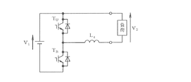
このように回路を構成することで、例えば特許第3223842号公報によれば、図12に示す3相インバータの零相等価回路は図13となり、降圧コンバータを構成することができる。図13において、TUはインバータINVの上アームのスイッチング素子に、TBは同じく下アームのスイッチング素子に、LzはモータM1の巻線のリアクトルにそれぞれ相当し、負荷は救援対象車両のバッテリーに相当する。
この回路の動作原理については、特許第3223842号公報に詳述されているため、ここでは省略する。
By configuring the circuit in this way, according to, for example, Japanese Patent No. 3223842, the zero-phase equivalent circuit of the three-phase inverter shown in FIG. 12 becomes FIG. 13, and a step-down converter can be configured. In Figure 13, T U is the switching elements of the upper arm of the inverter INV, T B is the switching device in the lower arm similarly, L z correspond respectively to the reactor windings of the motor M 1, the load relief target vehicle It corresponds to a battery.
Since the operation principle of this circuit is described in detail in Japanese Patent No. 3223842, it is omitted here.
上述した特許第3223842号公報には、救援車両のバッテリーBAT1の電圧V1と、モータM1の中性点と負側直流母線との間の電位差V2と、上アームのオンデューティD1との間に、数式1の関係があることが記載されている。

数式1によれば、上下アームのデューティを変えることで、モータM1の中性点と負側直流母線との間に接続される救援対象車両への供給電圧(充電電圧)を、0〜V1の間で任意の大きさに調整することができる。このことは、救援対象車両に対する充電電流を制御できることを意味し、定電流充電が可能である。従って、充電電圧の初期値を救援対象車両のバッテリー電圧に設定した状態でリレーRY1,RY2を閉じれば、突入電流が発生することはない。
According to
別の構成として、図14のようにモータM1の中性点と正側直流母線との間に負荷(救援対象車両のバッテリー)を接続した場合、3相インバータの零相等価回路は図15となり、同様に降圧コンバータを構成することができる。
つまり、モータM1の中性点とインバータINVの正負直流母線のいずれか一方との間から出力電圧を得ることにより、救援車両のバッテリーBAT1の電圧V1を入力とした降圧コンバータを構成することができる。
As another configuration, when a load (battery of the vehicle to be rescued) is connected between the neutral point of the motor M 1 and the positive DC bus as shown in FIG. 14, the zero-phase equivalent circuit of the three-phase inverter is shown in FIG. Thus, a step-down converter can be configured similarly.
That is, by obtaining the output voltage from between the one of the positive and negative DC bus of the neutral point and the inverter INV of the motor M 1, constitutes a buck converter with an input voltage V 1 of the battery BAT 1 rescue vehicle be able to.
次に、図12に示す回路を対象とした上下アームのデューティを変える手段について説明する。
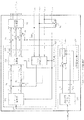
図16は、PWMパルス制御ブロックを示す図であり、SW1,SW2はスイッチ、9u,9v,9wは加減算器、12はPWM生成器を示す。また、図17はこのブロックによるPWMパルス生成方法を示す図である。
図17に示すように、PWM生成器12では、搬送波である三角波と信号波である電圧指令値vz *,vu1 *,vv1 *,vw1 *との大小を比較し、PWMパルスを生成する。
Next, means for changing the duty of the upper and lower arms for the circuit shown in FIG. 12 will be described.
FIG. 16 is a diagram showing a PWM pulse control block, wherein SW 1 and SW 2 are switches, 9 u, 9 v and 9 w are adders / subtractors, and 12 is a PWM generator. FIG. 17 is a diagram showing a PWM pulse generation method using this block.
As shown in FIG. 17, the
上下アームのデューティを変える方法としては、図16のように、モータ駆動用の交流電圧指令値vu1 *,vv1 *,vw1 *をスイッチSW1により遮断し(vu1 *,vv1 *,vw1 *をそれぞれ零としてもよい)、一方、スイッチSW2を閉じて各相に同一の電圧指令値vz *を入力する。この結果、インバータINVの各相上下アームのスイッチング素子T11〜T16のオンオフは同一のパターンとなり、図13に示した降圧コンバータを構成するスイッチング素子TU,TBとして機能する。ここで、vz *を制御すれば、上下アームのデューティを変えることができるのは明白である。 As a method of changing the duty of the upper and lower arms, as shown in FIG. 16, AC voltage command values v u1 * , v v1 * , v w1 * for driving the motor are cut off by the switch SW 1 (v u1 * , v v1 * , V w1 * may be zero), while the switch SW 2 is closed and the same voltage command value v z * is input to each phase. As a result, the switching elements T 11 to T 16 of the upper and lower arms of the inverter INV are turned on and off in the same pattern, and function as the switching elements T U and T B constituting the step-down converter shown in FIG. Here, it is obvious that the duty of the upper and lower arms can be changed by controlling v z * .
図18は、予め決められた充電電流によって救援対象車両を充電するためのPWMパルス制御ブロックを示す図である。
前述した降圧コンバータの出力電流(充電電流)検出値izdetを帰還量とした電流調節器ACRを構成し、その出力を各相に入力する相電圧指令値vz *とすることで、予め決められた電流指令値Ic *に従って救援対象車両のバッテリーを充電することができる。なお、9aは加減算器である。
充電停止の判断手段としては、標準化された充電インターフェースを利用し、救援車両と救援対象車両との間で前記コネクタ4sを介して通信することにより救援対象車両に搭載されたバッテリーのSOCを取得し、その数値が予め設定したSOCに到達したら充電を停止すればよい。
FIG. 18 is a diagram illustrating a PWM pulse control block for charging a rescue target vehicle with a predetermined charging current.
By configuring the current regulator ACR using the above-described output current (charging current) detection value i zdet of the step-down converter as a feedback amount, the output is set as a phase voltage command value v z * to be input to each phase. The battery of the rescue target vehicle can be charged according to the current command value I c * . Reference numeral 9a denotes an adder / subtracter.
As a means for determining charging stop, a standardized charging interface is used, and the SOC of the battery mounted on the rescue target vehicle is acquired by communicating between the rescue vehicle and the rescue target vehicle via the
次に、図9は、本発明の第2実施形態に係る電気自動車駆動システムの構成図である。
図4との相違点を中心に説明すると、この第2実施形態では、救援車両のバッテリーBAT1の電圧を昇圧するDC/DCコンバータが付加されており、バッテリーBAT1の電圧をインバータINVの主回路のスイッチング素子T11〜T16の耐圧限度内で昇圧し、直流母線へ供給するように構成されている。
なお、600は、制御装置CONT2に設けられたDC/DCコンバータ制御装置である。
Next, FIG. 9 is a configuration diagram of an electric vehicle drive system according to a second embodiment of the present invention.
The difference from FIG. 4 will be mainly described. In the second embodiment, a DC / DC converter that boosts the voltage of the battery BAT 1 of the rescue vehicle is added, and the voltage of the battery BAT 1 is changed to the main voltage of the inverter INV. The voltage is boosted within the withstand voltage limit of the switching elements T 11 to T 16 of the circuit and supplied to the DC bus.
上記DC/DCコンバータ(昇圧コンバータ)は、インバータINVに並列接続されたスイッチング素子T21,T22の直列回路と、リアクトルL1とによって構成されており、リアクトルL1はコンデンサ3の一端とスイッチング素子T21,T22同士の直列接続点との間に接続されている。なお、3aはスイッチング素子T21,T22の直列回路に並列接続されたコンデンサ、7aは電流検出器である。
The DC / DC converter (boost converter) includes a series circuit of the switching elements T 21, T 22 connected in parallel to the inverter INV, is constituted by a reactor L 1, one end and the switching of the reactor L 1 is a
ここで、バッテリーBAT1の電圧V1と直流母線電圧V3との間には数式2の関係があることが知られている。なお、便宜的に、上アームのオン時間T21はスイッチング素子T21と同一符号を使用する。
すなわち、スイッチング素子T21,T22の上下アームのデューティ比と、スイッチング素子T11〜T16の上下アームのデューティ比とを変えることで、救援車両のバッテリーBAT1の電圧V1を任意の大きさの電圧に調整することができる。このことは、救援対象車両が必要とする充電電圧が救援車両のバッテリー電圧V1より高くても、救援対象車両のバッテリーに所要の充電電流を制御できることを意味しており、定電流急速充電することが可能である。 That is, by changing the duty ratio of the upper and lower arms of the switching elements T 21 and T 22 and the duty ratio of the upper and lower arms of the switching elements T 11 to T 16 , the voltage V 1 of the battery BAT 1 of the rescue vehicle is arbitrarily increased. The voltage can be adjusted. This is also the charging voltage rescue target vehicle is required higher than the battery voltage V 1 of the rescue vehicle, which means that you can control the required charging current to the battery relief target vehicle, constant current fast charge It is possible.
次に、本発明の実施例を説明する。
図1は、請求項1,4,5に相当する本発明の第1実施例を示している。この第1実施例は、前述した図4の第1実施形態に基づいて構成されており、電流検出器、電圧検出器等の図示は省略してある。また、第1実施例に係る充電装置が搭載された車両を救援車両101とし、この救援車両101によってバッテリーが充電される車両を救援対象車両102とする。
Next, examples of the present invention will be described.
FIG. 1 shows a first embodiment of the present invention corresponding to
救援車両101はコネクタ4sに急速充電用出力端子を備え、救援対象車両102のコネクタ4rの急速充電用入力端子に、ケーブル5を介して接続される。このケーブル5により、充電電流及び充電制御用の制御信号が伝送される。接続部としてのコネクタ4r,4sの構造仕様、電気仕様及び通信仕様は、標準化された急速充電用の規格が採用されている。また、充電開始及び終了手順は、標準化された急速充電シーケンス仕様にて行われるものとする。
一方、救援対象車両102は、例えば電気自動車やハイブリッド自動車であり、前記コネクタ4rと、リレー2d,2e、バッテリーBAT2、制御装置CONTrを備えている。
The
On the other hand, the
次に、救援車両101の制御装置CONT1の構成を、図4に基づいて説明する。
この制御装置CONT1は、下位制御装置であるバッテリー管理装置100、インバータ制御装置300、充電制御装置400と、これらを統合的に制御する上位制御装置500とを備え、上位制御装置500には、救援対象車両102への充電量を設定する充電量設定器200が接続されている。これらの各装置は、A/D変換機能、メモリ機能及び通信機能を有するマイクロコンピュータ及び液晶タッチパネル等により構成されている。
なお、com,com1,com2,com3は通信信号である。
Next, the configuration of the control device CONT 1 of the
The control device CONT 1 includes a
Note that com, com 1 , com 2 , and com 3 are communication signals.
上位制御装置500は、車両の運転指令、充電開始指令、及び、充電量設定器200により設定された救援対象車両102の充電量設定値を、下位制御装置(バッテリー管理装置100、インバータ制御装置300、充電制御装置400)へ伝達する。
充電量設定器200は、目標とする充電量設定値を入力とするヒューマンインタフェース装置であり、設定されたデータを上位制御装置500へ伝送する。
バッテリー管理装置100は、自車のバッテリーBAT1のSOCやSOH等をモニタするモニタ手段、救援対象車両102のバッテリーBAT2に対する充電仕様を伝送する手段からなる。
The
The charge
The
インバータ制御装置300は、図5に示すように構成されている。
このインバータ制御装置300は、通信信号処理ブロック310、モータ制御ブロック320、充電電流制御ブロック330、及び、スイッチング素子T11〜T16を駆動するゲート信号を発生するPWM生成器12を備えている。
モータ制御ブロック320への入力信号は、救援車両101を駆動するモータM1のトルク指令値T*、インバータ出力相電流検出値iudet,ivdet,iwdet、モータM1の磁極位置検出信号θdetであり、充電電流制御ブロック330への入力信号は、救援対象車両102に対する充電電流指令値Ic *、ACRホールド信号hold、及び、電流調節器ACR3の出力電圧初期値vzini *である。
ここで、加減算器9cにより算出されるインバータ出力相電流検出値iudet,ivdet,iwdetの和izdetは充電電流検出値となり、充電電流指令値Ic *との偏差が加減算器9bにより算出されて電流調節器ACR3に入力されている。
The
The
The input signals to the
Here, the sum i zdet of the inverter output phase current detection values i udet , i vdet , i wdet calculated by the adder /
モータ制御ブロック320は、ベクトル演算器321、ベクトル回転器322,323、電流調節器ACR1,ACR2、加減算器9d,9q、スイッチSW1を備えている。そして、ベクトル回転器322から出力される各相電圧指令値vu1 *,vv1 *,vw1 *に電圧指令値vz *を加算して得た電圧指令値vu2 *,vv2 *,vw2 *がPWM生成器12に入力され、その出力が3相インバータINVの6つのスイッチング素子T11〜T16を駆動するゲート信号となる。
救援車両101の通常走行状態では、モータ制御ブロック320が動作し、上位制御装置500からトルク指令T*を受けて、この指令T*に対応したトルクを発生するようにベクトル演算器321によりd軸,q軸のモータ電流指令値id *,iq *を演算する。電流調節器ACR1,ACR2は、モータM1に3相交流電圧を印加するためのものであり、その制御方法として、永久磁石同期電動機を駆動するベクトル制御を用いる。このベクトル制御方法は周知であるため、ここでは詳述を省略する。
電圧指令値切替用のスイッチSW1を閉じ、これらと相補の関係になっているスイッチSW2を開くことにより、PWM生成器12がPWM演算を行う電圧指令値を、電流調節器ACR1,ACR2の出力とする。
従って、通常走行状態においては通常の3相インバータによるモータ駆動となんら変わらない制御となる。
In the normal traveling state of the
By closing the switch SW 1 for switching the voltage command value and opening the switch SW 2 which is complementary to these, the voltage command value for the
Therefore, in the normal running state, the control is not different from the motor driving by the normal three-phase inverter.
次に、救援対象車両102のバッテリーBAT2を充電する動作について説明する。
この場合には、スイッチSW2を閉じ、これと相補の関係になっているスイッチSW1を開くことにより、PWM生成器12がPWM演算を行う電圧指令値を、充電電流制御ブロック330内の電流調節器ACR3の出力とする。
電流調節器ACR3の入力である充電電流指令値Ic *は、コネクタ4r,4s経由の通信により救援対象車両102から得た許容充電電流値とする。
Next, an operation of charging the battery BAT 2 of the
In this case, by closing the switch SW 2 and opening the switch SW 1 that is complementary to the switch SW 2 , the voltage command value at which the
The charging current command value I c * , which is the input of the current regulator ACR3, is an allowable charging current value obtained from the
次いで、図4における充電制御装置400について、図6に基づいて説明する。
図6に示すように、充電制御装置400は、初期電圧検出部401、通信信号処理部402,403、充電シーケンス制御装置404から構成されている。
すなわち、充電制御装置400は、上位制御装置500からの充電開始信号及び目標充電量SOC*(通信信号com1)、救援対象車両102との双方向通信信号com、救援対象車両102のバッテリー電圧検出値VBAT2detを入力とし、充電電流指令値及び充電初期電圧を、上位制御装置500を経由してインバータ制御装置300へ出力する。通信信号処理部402は、充電開始のタイミングで充電シーケンス制御装置404に対するhold信号を解除し、充電電流を救援対象車両102へ通流する指令をインバータ制御装置300に与える。上述した充電制御装置400の機能は必要最低限であるが、搭載機能は標準化された急速充電仕様に適合させることが望ましい。
Next, the charging
As shown in FIG. 6, the charging
That is, the charging
これらの制御ブロックにより図7に示すフローチャートを実行することで、救援車両101から救援対象車両102への充電が可能である。
図7は、この実施例における救援対象車両102への充電動作を示すフローチャートである。救援対象車両102のバッテリーBAT2の電圧を検出し、この電圧を電流調節器ACR3の積分器にプリセットしてリレーRY1,RY2を閉じ、hold信号の解除を待って電流調節器ACR3を動作させる(ステップS1〜S6)。そして、救援対象車両102のバッテリーBAT2のSOCが設定値を超えたら、電流調節器ACR3の電流指令値を零に設定し、リレーRY1,RY2を開いて電流調節器ACR3の動作を停止すると共に、充電完了信号を救援対象車両102に送信する(ステップS7〜S11)。
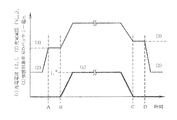
なお、図8は、図7に対応するタイムチャートであり、(1)充電電流Ic、(2)充電電圧Vout、(3)バッテリーBAT2の電圧を示している。
By executing the flowchart shown in FIG. 7 using these control blocks, charging from the
FIG. 7 is a flowchart showing the charging operation to the
FIG. 8 is a time chart corresponding to FIG. 7 and shows (1) charging current I c , (2) charging voltage V out , and (3) voltage of battery BAT 2 .
次に、図2は請求項2に相当する本発明の第2実施例を示している。この第2実施例は、前述した図9の第2実施形態に基づいて構成されており、電流検出器、電圧検出器等の図示は省略してある。
図2の第2実施例が図1の第1実施例と異なる点は、図9において説明したように、救援車両101のバッテリーBAT1の電圧を昇圧コンバータにより昇圧する機能が付加されている点である。
第2実施例における救援車両101の制御装置CONT2の構成は、前述した図9に示したとおりであり、充電制御方法は、以下の説明を除いて第1実施例と同様である。
FIG. 2 shows a second embodiment of the present invention corresponding to the second aspect. The second example is configured based on the second embodiment of FIG. 9 described above, and illustration of a current detector, a voltage detector, and the like is omitted.
The second embodiment of FIG. 2 is different from the first embodiment of FIG. 1 in that a function of boosting the voltage of the battery BAT 1 of the
The configuration of the control device CONT 2 of the
前述した数式3より、救援車両101からの充電出力電圧は、DC/DCコンバータ側の上下アームスイッチング素子T21,T22のデューティと、3相インバータINV側の上下アームスイッチング素子T11,T12,T13及びT14,T15,T16のデューティとの双方によって制御可能であるが、3相インバータINV側の上下アームのデューティを制御して充電電流制御を行うため、DC/DCコンバータ側の上下アームのデューティは固定とする。その固定値は、直流母線電圧が救援対象車両102のバッテリーBAT2の充電終止電圧Vendとなる値とする。この結果、前述した数式3より、充電出力電圧は数式4となる。
なお、昇圧コンバータの制御方法は周知であるため、説明を省略する。
From
Since the control method of the boost converter is well known, the description is omitted.
次いで、図3は請求項3に相当する本発明の第3実施例を示している。
この第3実施例と第1,第2実施例との相違点は、救援車両101内に、エンジン700、発電機800と、自車のバッテリーBAT1を充電するための自車充電装置900とを付加した点である。
FIG. 3 shows a third embodiment of the present invention corresponding to the third aspect.
The difference between the third embodiment and the first and second embodiments is that an
図10は、図3を具体化した救援車両101の構成を示す制御ブロック図である。
エンジン700は発電指令により起動され、予め設定された回転数で動作し、機械軸6を介して発電機800を駆動する。発電機800は、3相交流同期発電機とする。
FIG. 10 is a control block diagram showing the configuration of the
The
図11は、自車の充電を行う自車充電装置900の構成を示している。
自車充電装置900は、発電機800の3相交流出力端子R,S,Tから入力された電流を整流するダイオードD1〜D6からなる整流回路、自車のバッテリーBAT1の正極BAT1(+)、負極BAT1(−)に充電電流を供給するスイッチング素子TU2,TB2、バッテリーBAT1のSOCを演算するSOC演算手段901、演算されたSOCに基づいて充電電流を決定する充電電流決定手段902、決定した充電電流にて電流を制御する電流調節器904及びPWM生成器905、演算されたSOCに基づきエンジン700の発電指令を出力し、その起動、停止を制御するエンジン起動、停止判定手段903から構成されている。3b,3cはコンデンサ、L2はリアクトル、7bは電流検出器、9eは加減算器である。
FIG. 11 shows the configuration of a
The own
SOC演算手段901は、バッテリーBAT1の充放電電流を計測して電流値を積算することでSOCを演算する。VBAT1detはバッテリーBAT1の電圧検出値、iBAT1detはバッテリーBAT1の電流検出値である。なお、SOCを演算する具体的な方法は、例えば特開2005−354825号公報等に開示されているので、詳述は省略する。
充電電流決定手段902は、SOCに対するバッテリーBAT1の充電電流受け入れ特性から充電電流を決定する。
エンジン起動、停止判定手段903は、予め決められたSOCを閾値とし、SOC演算手段901により演算されたSOCが閾値以上のときにエンジン700を停止し、閾値未満のときにエンジン700を起動する信号Egctrを出力する。
The SOC calculation means 901 calculates the SOC by measuring the charge / discharge current of the battery BAT 1 and integrating the current values. V BAT1det the voltage detection value of the battery BAT 1, i BAT1det is a current detection value of the battery BAT 1. A specific method for calculating the SOC is disclosed in, for example, Japanese Patent Application Laid-Open No. 2005-354825, and the detailed description thereof is omitted.
Charging current determining means 902 determines the charging current from the charging current acceptance characteristic of battery BAT 1 with respect to the SOC.
The engine start /
この第3実施例によれば、上述した機能を付加することにより、第1,第2実施例により説明した救援対象車両102に対する充電が可能であることに加え、救援車両101のバッテリーBAT1を自車に搭載されたエンジン700によって充電することができる。
According to the third embodiment, by adding the above-described function, the
なお、本発明は、救援対象車両102が電気自動車やハイブリッド自動車である場合だけでなく、通常のガソリン自動車や電動式自転車である場合にも適用可能である。
The present invention can be applied not only when the
1:抵抗器
2a,2b,2c:リレー
3,3a,3b,3c:コンデンサ
4,4s,4r:標準化された急速充電用コネクタ
5:ケーブル
6:機械軸
7,7a,7b,7u,7v,7w:電流検出器
8,8a:電圧検出器
9,9a,9b,9c,9d,9e,9q,9u,9v,9w:加減算器
10:磁極位置検出器
11:コネクタ
12:PWM生成器
100:バッテリー管理装置
101:救援車両
102:救援対象車両
200:充電量設定器
300:インバータ制御装置
310:通信信号処理ブロック
320:モータ制御ブロック
330:充電電流制御ブロック
321:ベクトル演算器
322,323:ベクトル回転器
400:充電制御装置
401:初期電圧検出部
402,403:通信信号処理部
403:充電シーケンス制御装置
500:上位制御装置
600:DC/DCコンバータ制御装置
700:エンジン
800:発電機
900:自車充電装置
901:SOC演算手段
902:充電電流決定手段
903:エンジン起動、停止判定手段
904:電流調節器
905:PWM生成器
CONT1,CONT2,CONT3,CONTr:制御装置
M1:モータ
BAT1:救援車両のバッテリー
BAT2:救援対象車両のバッテリー
T11〜T16,T21,T22,TU,TB,TU2,TB2:スイッチング素子
L1,L2,Lz:リアクトル
ACR,ACR1,ACR2,ACR3:電流調節器
RY1,RY2:リレー
D1〜D6:ダイオード
SW1,SW2:スイッチ
1: Resistor 2a, 2b, 2c: Relay 3, 3a, 3b, 3c: Capacitor 4, 4s, 4r: Standardized quick charging connector 5: Cable 6: Mechanical shaft 7, 7a, 7b, 7u, 7v, 7w: current detector 8, 8a: voltage detector 9, 9a, 9b, 9c, 9d, 9e, 9q, 9u, 9v, 9w: adder / subtractor 10: magnetic pole position detector 11: connector 12: PWM generator 100: Battery management device 101: rescue vehicle 102: rescue target vehicle 200: charge amount setting device 300: inverter control device 310: communication signal processing block 320: motor control block 330: charge current control block 321: vector calculator 322, 323: vector Rotator 400: Charge control device 401: Initial voltage detection unit 402, 403: Communication signal processing unit 403: Charge sequence Control device 500: host control device 600: DC / DC converter control device 700: engine 800: generator 900: own vehicle charging device 901: SOC calculation means 902: charging current determination means 903: engine start / stop determination means 904: current regulator 905: PWM generator CONT 1, CONT 2, CONT 3 , CONT r: control device M 1: motor BAT 1: battery rescue vehicle BAT 2: battery T 11 relief target vehicle ~T 16, T 21, T 22, T U, T B , T U2, T B2: switching elements L 1, L 2, L z : reactor ACR, ACR1, ACR2, ACR3: current regulator RY 1, RY 2: relay D 1 to D 6 : diode SW 1, SW 2: switch
Claims (5)
前記モータの中性点と前記インバータの正負直流母線の一方とから出力される充電電流を前記救援対象車両のバッテリーに供給し、かつ、前記救援対象車両のバッテリーに充電するための制御信号を前記制御装置と前記救援対象車両との間で送受信する接続部を備えたことを特徴とする車両間充電装置。 To a battery, an inverter for converting a DC voltage of the battery into an AC voltage, a vehicle driving motor driven by the inverter, a management function of the battery, a control function of the inverter, and a battery of another rescue target vehicle In the inter-vehicle charging device capable of charging the battery of the rescue target vehicle by a rescue vehicle equipped with a control device having a charge control function of
Supplying a charging current output from the neutral point of the motor and one of the positive and negative DC buses of the inverter to the battery of the rescue target vehicle, and a control signal for charging the battery of the rescue target vehicle A vehicle-to-vehicle charging device comprising a connection for transmitting and receiving between the control device and the rescue target vehicle.
前記モータの中性点と前記インバータの正負直流母線の一方とから出力される充電電流を前記救援対象車両のバッテリーに供給し、かつ、前記救援対象車両のバッテリーに充電するための制御信号を前記制御装置と前記救援対象車両との間で送受信する接続部を備えたことを特徴とする車両間充電装置。 Battery, converter for boosting DC voltage of battery, inverter for converting DC output voltage of converter to AC voltage, vehicle driving motor driven by inverter, battery management function, converter And a control device having a control function of the inverter, a control device having a charge control function to a battery of another rescue target vehicle, and a vehicle-to-vehicle charging device capable of charging the battery of the rescue target vehicle by a rescue vehicle,
Supplying a charging current output from the neutral point of the motor and one of the positive and negative DC buses of the inverter to the battery of the rescue target vehicle, and a control signal for charging the battery of the rescue target vehicle A vehicle-to-vehicle charging device comprising a connection for transmitting and receiving between the control device and the rescue target vehicle.
前記救援車両は、エンジンと、前記エンジンにより駆動される発電機とを備え、かつ、前記発電機により前記救援車両のバッテリーを充電する充電制御機能を有することを特徴とする車両間充電装置。 In the inter-vehicle charging device according to claim 1 or 2,
The rescue vehicle includes an engine and a generator driven by the engine, and has a charge control function of charging a battery of the rescue vehicle by the generator.
前記救援車両は、前記救援対象車両のバッテリーに対する充電量を指定する機能を備えたことを特徴とする車両間充電装置。 In the inter-vehicle charging device according to any one of claims 1 to 3,
The rescue vehicle includes a function of designating a charge amount for a battery of the rescue target vehicle.
前記接続部が、標準化された急速充電用のコネクタを有することを特徴とする車両間充電装置。 In the inter-vehicle charging device according to any one of claims 1 to 4,
The inter-vehicle charging device, wherein the connecting portion has a standardized quick charging connector.
Priority Applications (2)
| Application Number | Priority Date | Filing Date | Title |
|---|---|---|---|
| JP2011060081A JP5660317B2 (en) | 2011-03-18 | 2011-03-18 | Inter-vehicle charger |
| CN201210058530.2A CN102684248B (en) | 2011-03-18 | 2012-03-07 | Charging device between vehicle |
Applications Claiming Priority (1)
| Application Number | Priority Date | Filing Date | Title |
|---|---|---|---|
| JP2011060081A JP5660317B2 (en) | 2011-03-18 | 2011-03-18 | Inter-vehicle charger |
Publications (2)
| Publication Number | Publication Date |
|---|---|
| JP2012196105A true JP2012196105A (en) | 2012-10-11 |
| JP5660317B2 JP5660317B2 (en) | 2015-01-28 |
Family
ID=46815785
Family Applications (1)
| Application Number | Title | Priority Date | Filing Date |
|---|---|---|---|
| JP2011060081A Expired - Fee Related JP5660317B2 (en) | 2011-03-18 | 2011-03-18 | Inter-vehicle charger |
Country Status (2)
| Country | Link |
|---|---|
| JP (1) | JP5660317B2 (en) |
| CN (1) | CN102684248B (en) |
Cited By (21)
| Publication number | Priority date | Publication date | Assignee | Title |
|---|---|---|---|---|
| JP2013243898A (en) * | 2012-05-23 | 2013-12-05 | Fuji Electric Co Ltd | Charging apparatus |
| JP2014087145A (en) * | 2012-10-23 | 2014-05-12 | Fuji Electric Co Ltd | Charging device and charging method |
| CN104935068A (en) * | 2015-07-07 | 2015-09-23 | 国网电力科学研究院武汉南瑞有限责任公司 | An electric automobile rescue car power supply system ground simulation device |
| CN105048820A (en) * | 2015-07-30 | 2015-11-11 | 南京航空航天大学 | Motor driver of integrated DC-DC converter for electric vehicle |
| JP2015233355A (en) * | 2014-06-09 | 2015-12-24 | 日産自動車株式会社 | Charging system, power supply vehicle, charged vehicle, and charging method |
| JP2015233356A (en) * | 2014-06-09 | 2015-12-24 | 日産自動車株式会社 | Power supply vehicle, charging system, and charging method |
| KR20160052134A (en) | 2014-11-04 | 2016-05-12 | 현대자동차주식회사 | Battery charging apparatus and method for charging from one vehicle to other vehicle using the same |
| JP2016528862A (en) * | 2013-06-28 | 2016-09-15 | ビーワイディー カンパニー リミテッドByd Company Limited | Electric vehicle and charging connector for mutual charging |
| JP2018201328A (en) * | 2014-09-04 | 2018-12-20 | フラウンホーファー−ゲゼルシャフト・ツール・フェルデルング・デル・アンゲヴァンテン・フォルシュング・アインゲトラーゲネル・フェライン | Apparatus for charging energy storage device |
| KR20190029382A (en) * | 2017-09-12 | 2019-03-20 | 현대오트론 주식회사 | Vehicle power control device |
| KR20190029870A (en) * | 2017-09-12 | 2019-03-21 | 현대오트론 주식회사 | Vehicle power control device |
| CN110203090A (en) * | 2019-05-07 | 2019-09-06 | 北京九曜智能科技有限公司 | Movable charging vehicle and its charging method |
| CN110356260A (en) * | 2019-07-19 | 2019-10-22 | 中汽研(天津)汽车工程研究院有限公司 | It is a kind of to fill benefit electric installation applied to the portable of electric vehicle roadside assistance |
| CN111355414A (en) * | 2018-12-21 | 2020-06-30 | 比亚迪股份有限公司 | Vehicle, motor drive device, control method, and readable storage medium |
| CN111355432A (en) * | 2018-12-21 | 2020-06-30 | 比亚迪股份有限公司 | Motor driving apparatus, control method, vehicle, and readable storage medium |
| CN111684696A (en) * | 2018-02-22 | 2020-09-18 | 株式会社自动网络技术研究所 | Vehicle-mounted DCDC converter |
| CN112297893A (en) * | 2019-07-31 | 2021-02-02 | 比亚迪股份有限公司 | Discharging vehicle and vehicle charging system |
| US11165275B2 (en) * | 2019-08-30 | 2021-11-02 | Hyundai Motor Company | Charging system and method using motor driving system |
| EP4052956A1 (en) * | 2021-03-05 | 2022-09-07 | Volvo Car Corporation | Vehicle-to-vehicle charging |
| DE102015102481B4 (en) | 2014-02-21 | 2024-02-22 | Infineon Technologies Ag | Circuit, electric drive train and method for charging a battery |
| DE102022210978A1 (en) | 2022-10-18 | 2024-04-18 | Robert Bosch Gesellschaft mit beschränkter Haftung | Power converter device for converting an input DC voltage into an output DC voltage, electric drive and charging system and method for determining an electrical output current |
Families Citing this family (17)
| Publication number | Priority date | Publication date | Assignee | Title |
|---|---|---|---|---|
| KR101448776B1 (en) * | 2013-02-22 | 2014-10-13 | 현대자동차 주식회사 | Integrated electronic power control unit sharing dc input part of environmentally friendly vehicle |
| CN105762876A (en) * | 2015-11-04 | 2016-07-13 | 郑州宇通客车股份有限公司 | Automobile-to-automobile charging machine, automobile-to-automobile charging system and automobile-to-automobile charging method |
| US10434898B2 (en) * | 2016-09-09 | 2019-10-08 | Ford Global Technologies, Llc | Electrified vehicle with expansion interface mechanism for interfacing with secondary electrical device |
| DE102017123346A1 (en) * | 2017-10-09 | 2019-04-11 | Dr. Ing. H.C. F. Porsche Aktiengesellschaft | A method for initializing a DC charging of a battery by means of an inverter |
| US10454395B2 (en) * | 2017-11-06 | 2019-10-22 | Steering Solutions Ip Holding Corporation | Power management in permanent magnet synchronous motor drives |
| CN110015084A (en) * | 2017-11-16 | 2019-07-16 | 北汽(镇江)汽车有限公司 | A kind of automobile is to automobile charging system actual, automobile and its control method |
| KR102565333B1 (en) * | 2018-12-12 | 2023-08-16 | 현대자동차주식회사 | Apparatus of controlling charging system using motor driving system |
| CN112389268B (en) * | 2019-08-15 | 2022-11-11 | 比亚迪股份有限公司 | Electric automobile and integrated controller and integrated control system thereof |
| CN112389348B (en) * | 2019-08-15 | 2022-12-09 | 比亚迪股份有限公司 | Electric automobile and integrated controller and integrated control system thereof |
| CN112389270B (en) | 2019-08-15 | 2022-07-15 | 比亚迪股份有限公司 | Energy conversion device and vehicle |
| CN112389267B (en) * | 2019-08-15 | 2023-01-10 | 比亚迪股份有限公司 | Electric automobile and integrated controller and integrated control system thereof |
| CN112751396B (en) * | 2019-10-31 | 2023-01-06 | 比亚迪股份有限公司 | Energy conversion device and vehicle |
| CN112757927B (en) * | 2020-12-30 | 2022-06-07 | 重庆金康动力新能源有限公司 | Extended range vehicle charging and discharging control method and system |
| CN114683991A (en) * | 2020-12-31 | 2022-07-01 | 宝能汽车集团有限公司 | Rescue vehicle and external discharging method thereof |
| CN112776624A (en) * | 2021-02-03 | 2021-05-11 | 爱驰汽车有限公司 | Vehicle-to-vehicle charging system and method and electric vehicle |
| CN113147439A (en) * | 2021-05-07 | 2021-07-23 | 齐齐哈尔大学 | New energy automobile rescue trailer system and method |
| CN114590140B (en) * | 2022-03-30 | 2023-07-14 | 华人运通(江苏)技术有限公司 | Charging and discharging management system of electric automobile |
Citations (12)
| Publication number | Priority date | Publication date | Assignee | Title |
|---|---|---|---|---|
| US7015A (en) * | 1850-01-15 | Dampeb fob | ||
| US8009A (en) * | 1851-04-01 | Improvement in mills for grinding paints and drugs | ||
| JP2000324857A (en) * | 1999-03-11 | 2000-11-24 | Toyota Motor Corp | Variety of power units, and equipment, motor driver, and hybrid vehicle provided with the same |
| JP2003102181A (en) * | 2001-09-25 | 2003-04-04 | Toyota Motor Corp | System and method for electric power supply |
| JP2005033954A (en) * | 2003-07-09 | 2005-02-03 | Toyota Motor Corp | Battery charger |
| JP2006034065A (en) * | 2004-07-21 | 2006-02-02 | Nissan Motor Co Ltd | Charge controller for vehicle |
| JP2006158124A (en) * | 2004-11-30 | 2006-06-15 | Toyota Motor Corp | Power supply system and vehicle |
| JP2009077492A (en) * | 2007-09-19 | 2009-04-09 | Fuji Electric Systems Co Ltd | Power conversion system and electric drive vehicle |
| JP2010187466A (en) * | 2009-02-12 | 2010-08-26 | Omron Corp | Battery charging device for vehicle |
| JP2010207029A (en) * | 2009-03-05 | 2010-09-16 | Fujitsu Ten Ltd | Controller and control method |
| JP2010252520A (en) * | 2009-04-15 | 2010-11-04 | Nissan Motor Co Ltd | Inter-vehicle charging method, inter-vehicle charging cable and electric vehicle |
| WO2011026721A2 (en) * | 2009-09-02 | 2011-03-10 | Robert Bosch Gmbh | Jump start method and device for carrying out said method |
Family Cites Families (4)
| Publication number | Priority date | Publication date | Assignee | Title |
|---|---|---|---|---|
| JP3780550B2 (en) * | 1995-12-08 | 2006-05-31 | アイシン・エィ・ダブリュ株式会社 | Control device for vehicle drive device |
| DE19823917A1 (en) * | 1997-06-03 | 1998-12-10 | Fuji Electric Co Ltd | Converter for producing multiphase AC current |
| JP3615445B2 (en) * | 2000-01-31 | 2005-02-02 | 三洋電機株式会社 | Hybrid car power supply |
| JP4218610B2 (en) * | 2004-08-06 | 2009-02-04 | 日産自動車株式会社 | Electric vehicle power supply |
-
2011
- 2011-03-18 JP JP2011060081A patent/JP5660317B2/en not_active Expired - Fee Related
-
2012
- 2012-03-07 CN CN201210058530.2A patent/CN102684248B/en not_active Expired - Fee Related
Patent Citations (12)
| Publication number | Priority date | Publication date | Assignee | Title |
|---|---|---|---|---|
| US7015A (en) * | 1850-01-15 | Dampeb fob | ||
| US8009A (en) * | 1851-04-01 | Improvement in mills for grinding paints and drugs | ||
| JP2000324857A (en) * | 1999-03-11 | 2000-11-24 | Toyota Motor Corp | Variety of power units, and equipment, motor driver, and hybrid vehicle provided with the same |
| JP2003102181A (en) * | 2001-09-25 | 2003-04-04 | Toyota Motor Corp | System and method for electric power supply |
| JP2005033954A (en) * | 2003-07-09 | 2005-02-03 | Toyota Motor Corp | Battery charger |
| JP2006034065A (en) * | 2004-07-21 | 2006-02-02 | Nissan Motor Co Ltd | Charge controller for vehicle |
| JP2006158124A (en) * | 2004-11-30 | 2006-06-15 | Toyota Motor Corp | Power supply system and vehicle |
| JP2009077492A (en) * | 2007-09-19 | 2009-04-09 | Fuji Electric Systems Co Ltd | Power conversion system and electric drive vehicle |
| JP2010187466A (en) * | 2009-02-12 | 2010-08-26 | Omron Corp | Battery charging device for vehicle |
| JP2010207029A (en) * | 2009-03-05 | 2010-09-16 | Fujitsu Ten Ltd | Controller and control method |
| JP2010252520A (en) * | 2009-04-15 | 2010-11-04 | Nissan Motor Co Ltd | Inter-vehicle charging method, inter-vehicle charging cable and electric vehicle |
| WO2011026721A2 (en) * | 2009-09-02 | 2011-03-10 | Robert Bosch Gmbh | Jump start method and device for carrying out said method |
Cited By (26)
| Publication number | Priority date | Publication date | Assignee | Title |
|---|---|---|---|---|
| JP2013243898A (en) * | 2012-05-23 | 2013-12-05 | Fuji Electric Co Ltd | Charging apparatus |
| JP2014087145A (en) * | 2012-10-23 | 2014-05-12 | Fuji Electric Co Ltd | Charging device and charging method |
| JP2016528862A (en) * | 2013-06-28 | 2016-09-15 | ビーワイディー カンパニー リミテッドByd Company Limited | Electric vehicle and charging connector for mutual charging |
| DE102015102481B4 (en) | 2014-02-21 | 2024-02-22 | Infineon Technologies Ag | Circuit, electric drive train and method for charging a battery |
| JP2015233355A (en) * | 2014-06-09 | 2015-12-24 | 日産自動車株式会社 | Charging system, power supply vehicle, charged vehicle, and charging method |
| JP2015233356A (en) * | 2014-06-09 | 2015-12-24 | 日産自動車株式会社 | Power supply vehicle, charging system, and charging method |
| JP2018201328A (en) * | 2014-09-04 | 2018-12-20 | フラウンホーファー−ゲゼルシャフト・ツール・フェルデルング・デル・アンゲヴァンテン・フォルシュング・アインゲトラーゲネル・フェライン | Apparatus for charging energy storage device |
| US10367363B2 (en) | 2014-09-04 | 2019-07-30 | Fraunhofer-Gesellschaft Zur Foerderung Der Angewandten Forschung E.V. | Device for charging an energy store |
| KR20160052134A (en) | 2014-11-04 | 2016-05-12 | 현대자동차주식회사 | Battery charging apparatus and method for charging from one vehicle to other vehicle using the same |
| CN104935068A (en) * | 2015-07-07 | 2015-09-23 | 国网电力科学研究院武汉南瑞有限责任公司 | An electric automobile rescue car power supply system ground simulation device |
| CN105048820B (en) * | 2015-07-30 | 2018-01-16 | 南京航空航天大学 | A kind of motor driver of integrated straight convertor used for electric vehicle |
| CN105048820A (en) * | 2015-07-30 | 2015-11-11 | 南京航空航天大学 | Motor driver of integrated DC-DC converter for electric vehicle |
| KR20190029382A (en) * | 2017-09-12 | 2019-03-20 | 현대오트론 주식회사 | Vehicle power control device |
| KR20190029870A (en) * | 2017-09-12 | 2019-03-21 | 현대오트론 주식회사 | Vehicle power control device |
| KR102008753B1 (en) | 2017-09-12 | 2019-08-09 | 현대오트론 주식회사 | Vehicle power control device |
| KR102008752B1 (en) | 2017-09-12 | 2019-08-12 | 현대오트론 주식회사 | Vehicle power control device |
| CN111684696A (en) * | 2018-02-22 | 2020-09-18 | 株式会社自动网络技术研究所 | Vehicle-mounted DCDC converter |
| CN111355414A (en) * | 2018-12-21 | 2020-06-30 | 比亚迪股份有限公司 | Vehicle, motor drive device, control method, and readable storage medium |
| CN111355432A (en) * | 2018-12-21 | 2020-06-30 | 比亚迪股份有限公司 | Motor driving apparatus, control method, vehicle, and readable storage medium |
| CN111355432B (en) * | 2018-12-21 | 2023-12-12 | 比亚迪股份有限公司 | Motor driving device, control method, vehicle, and readable storage medium |
| CN110203090A (en) * | 2019-05-07 | 2019-09-06 | 北京九曜智能科技有限公司 | Movable charging vehicle and its charging method |
| CN110356260A (en) * | 2019-07-19 | 2019-10-22 | 中汽研(天津)汽车工程研究院有限公司 | It is a kind of to fill benefit electric installation applied to the portable of electric vehicle roadside assistance |
| CN112297893A (en) * | 2019-07-31 | 2021-02-02 | 比亚迪股份有限公司 | Discharging vehicle and vehicle charging system |
| US11165275B2 (en) * | 2019-08-30 | 2021-11-02 | Hyundai Motor Company | Charging system and method using motor driving system |
| EP4052956A1 (en) * | 2021-03-05 | 2022-09-07 | Volvo Car Corporation | Vehicle-to-vehicle charging |
| DE102022210978A1 (en) | 2022-10-18 | 2024-04-18 | Robert Bosch Gesellschaft mit beschränkter Haftung | Power converter device for converting an input DC voltage into an output DC voltage, electric drive and charging system and method for determining an electrical output current |
Also Published As
| Publication number | Publication date |
|---|---|
| CN102684248A (en) | 2012-09-19 |
| CN102684248B (en) | 2015-10-14 |
| JP5660317B2 (en) | 2015-01-28 |
Similar Documents
| Publication | Publication Date | Title |
|---|---|---|
| JP5660317B2 (en) | Inter-vehicle charger | |
| US7834578B2 (en) | Load driving apparatus, vehicle, and abnormality processing method at load driving apparatus | |
| US10988043B2 (en) | Vehicle and method of charging electric power storage device | |
| EP2416475B1 (en) | Electric power generating system with boost converter/synchronous active filter | |
| US8487636B2 (en) | Malfunction determining apparatus and malfunction determining method for charging system | |
| US20160164289A1 (en) | Electric-power supply system, and vehicle | |
| US6384559B2 (en) | Electric power equipment for electric vehicle | |
| KR20050003732A (en) | A vector-controlled dual inverter system for an induction motor | |
| JP5945954B2 (en) | Charging apparatus and charging method | |
| CN104181472A (en) | Method of detecting state of power cable in inverter system | |
| JP6306210B2 (en) | Power converter | |
| KR20120116722A (en) | Electric vehicle and operating method of the same | |
| JP5936745B1 (en) | Power converter for vehicle | |
| JP5945936B2 (en) | Charger | |
| CN111391665A (en) | Charging system | |
| JP4934561B2 (en) | Power converter | |
| JP2006320074A (en) | Ac voltage output unit | |
| KR102010294B1 (en) | Electric vehicle and operating method of the same | |
| US20230278441A1 (en) | Bidirectional electric vehicle charging with multi-phase machines | |
| EP3965259A1 (en) | Charging device comprising inrush current limiter and control method thereof | |
| US11942889B2 (en) | Motor control device | |
| JP2006320072A (en) | Ac voltage output unit | |
| KR20130095082A (en) | Electric vehicle and operating method of the same | |
| KR101967561B1 (en) | Charging system and control method thereof | |
| JP5947528B2 (en) | Vehicle drive device, vehicle, and non-contact charging system |
Legal Events
| Date | Code | Title | Description |
|---|---|---|---|
| A621 | Written request for application examination |
Free format text: JAPANESE INTERMEDIATE CODE: A621 Effective date: 20140214 |
|
| A977 | Report on retrieval |
Free format text: JAPANESE INTERMEDIATE CODE: A971007 Effective date: 20141031 |
|
| TRDD | Decision of grant or rejection written | ||
| A01 | Written decision to grant a patent or to grant a registration (utility model) |
Free format text: JAPANESE INTERMEDIATE CODE: A01 Effective date: 20141105 |
|
| A61 | First payment of annual fees (during grant procedure) |
Free format text: JAPANESE INTERMEDIATE CODE: A61 Effective date: 20141118 |
|
| R150 | Certificate of patent or registration of utility model |
Ref document number: 5660317 Country of ref document: JP Free format text: JAPANESE INTERMEDIATE CODE: R150 |
|
| R250 | Receipt of annual fees |
Free format text: JAPANESE INTERMEDIATE CODE: R250 |
|
| R250 | Receipt of annual fees |
Free format text: JAPANESE INTERMEDIATE CODE: R250 |
|
| R250 | Receipt of annual fees |
Free format text: JAPANESE INTERMEDIATE CODE: R250 |
|
| R250 | Receipt of annual fees |
Free format text: JAPANESE INTERMEDIATE CODE: R250 |
|
| R250 | Receipt of annual fees |
Free format text: JAPANESE INTERMEDIATE CODE: R250 |
|
| RD02 | Notification of acceptance of power of attorney |
Free format text: JAPANESE INTERMEDIATE CODE: R3D02 |
|
| LAPS | Cancellation because of no payment of annual fees |