JP2012192643A - Image forming apparatus - Google Patents
Image forming apparatus Download PDFInfo
- Publication number
- JP2012192643A JP2012192643A JP2011058908A JP2011058908A JP2012192643A JP 2012192643 A JP2012192643 A JP 2012192643A JP 2011058908 A JP2011058908 A JP 2011058908A JP 2011058908 A JP2011058908 A JP 2011058908A JP 2012192643 A JP2012192643 A JP 2012192643A
- Authority
- JP
- Japan
- Prior art keywords
- valve
- valve body
- exhaust
- liquid tank
- image forming
- Prior art date
- Legal status (The legal status is an assumption and is not a legal conclusion. Google has not performed a legal analysis and makes no representation as to the accuracy of the status listed.)
- Granted
Links
Images


Classifications
-
- B—PERFORMING OPERATIONS; TRANSPORTING
- B41—PRINTING; LINING MACHINES; TYPEWRITERS; STAMPS
- B41J—TYPEWRITERS; SELECTIVE PRINTING MECHANISMS, i.e. MECHANISMS PRINTING OTHERWISE THAN FROM A FORME; CORRECTION OF TYPOGRAPHICAL ERRORS
- B41J2/00—Typewriters or selective printing mechanisms characterised by the printing or marking process for which they are designed
- B41J2/005—Typewriters or selective printing mechanisms characterised by the printing or marking process for which they are designed characterised by bringing liquid or particles selectively into contact with a printing material
- B41J2/01—Ink jet
- B41J2/135—Nozzles
- B41J2/165—Preventing or detecting of nozzle clogging, e.g. cleaning, capping or moistening for nozzles
- B41J2/16517—Cleaning of print head nozzles
- B41J2/1652—Cleaning of print head nozzles by driving a fluid through the nozzles to the outside thereof, e.g. by applying pressure to the inside or vacuum at the outside of the print head
- B41J2/16523—Waste ink collection from caps or spittoons, e.g. by suction
-
- B—PERFORMING OPERATIONS; TRANSPORTING
- B41—PRINTING; LINING MACHINES; TYPEWRITERS; STAMPS
- B41J—TYPEWRITERS; SELECTIVE PRINTING MECHANISMS, i.e. MECHANISMS PRINTING OTHERWISE THAN FROM A FORME; CORRECTION OF TYPOGRAPHICAL ERRORS
- B41J2/00—Typewriters or selective printing mechanisms characterised by the printing or marking process for which they are designed
- B41J2/005—Typewriters or selective printing mechanisms characterised by the printing or marking process for which they are designed characterised by bringing liquid or particles selectively into contact with a printing material
- B41J2/01—Ink jet
- B41J2/17—Ink jet characterised by ink handling
- B41J2/175—Ink supply systems ; Circuit parts therefor
- B41J2/17596—Ink pumps, ink valves
-
- Y—GENERAL TAGGING OF NEW TECHNOLOGICAL DEVELOPMENTS; GENERAL TAGGING OF CROSS-SECTIONAL TECHNOLOGIES SPANNING OVER SEVERAL SECTIONS OF THE IPC; TECHNICAL SUBJECTS COVERED BY FORMER USPC CROSS-REFERENCE ART COLLECTIONS [XRACs] AND DIGESTS
- Y10—TECHNICAL SUBJECTS COVERED BY FORMER USPC
- Y10T—TECHNICAL SUBJECTS COVERED BY FORMER US CLASSIFICATION
- Y10T137/00—Fluid handling
- Y10T137/2931—Diverse fluid containing pressure systems
- Y10T137/3003—Fluid separating traps or vents
- Y10T137/3084—Discriminating outlet for gas
- Y10T137/3087—With reverse flow stop or pressure regulating valve
-
- Y—GENERAL TAGGING OF NEW TECHNOLOGICAL DEVELOPMENTS; GENERAL TAGGING OF CROSS-SECTIONAL TECHNOLOGIES SPANNING OVER SEVERAL SECTIONS OF THE IPC; TECHNICAL SUBJECTS COVERED BY FORMER USPC CROSS-REFERENCE ART COLLECTIONS [XRACs] AND DIGESTS
- Y10—TECHNICAL SUBJECTS COVERED BY FORMER USPC
- Y10T—TECHNICAL SUBJECTS COVERED BY FORMER US CLASSIFICATION
- Y10T137/00—Fluid handling
- Y10T137/2931—Diverse fluid containing pressure systems
- Y10T137/3003—Fluid separating traps or vents
- Y10T137/3084—Discriminating outlet for gas
- Y10T137/309—Fluid sensing valve
Abstract
Description
本発明は画像形成装置に関し、特に液滴を吐出する記録ヘッドを備える画像形成装置に関する。 The present invention relates to an image forming apparatus, and more particularly to an image forming apparatus provided with a recording head for discharging droplets.
プリンタ、ファクシミリ、複写装置、プロッタ、これらの複合機等の画像形成装置として、例えばインク液滴を吐出する液体吐出ヘッド(液滴吐出ヘッド)からなる記録ヘッドを用いた液体吐出記録方式の画像形成装置としてインクジェット記録装置などが知られている。この液体吐出記録方式の画像形成装置は、記録ヘッドからインク滴を、搬送される用紙(紙に限定するものではなく、OHPなどを含み、インク滴、その他の液体などが付着可能なものの意味であり、被記録媒体あるいは記録媒体、記録紙、記録用紙などとも称される。)に対して吐出して、画像形成(記録、印字、印写、印刷も同義語で使用する。)を行なうものであり、記録ヘッドが主走査方向に移動しながら液滴を吐出して画像を形成するシリアル型画像形成装置と、記録ヘッドが移動しない状態で液滴を吐出して画像を形成するライン型ヘッドを用いるライン型画像形成装置がある。 As an image forming apparatus such as a printer, a facsimile, a copying machine, a plotter, or a complex machine of these, for example, a liquid discharge recording type image forming using a recording head composed of a liquid discharge head (droplet discharge head) that discharges ink droplets. As an apparatus, an ink jet recording apparatus or the like is known. This liquid discharge recording type image forming apparatus means that ink droplets are transported from a recording head (not limited to paper, including OHP, and can be attached to ink droplets and other liquids). Yes, it is also ejected onto a recording medium or a recording medium, recording paper, recording paper, etc.) to form an image (recording, printing, printing, and printing are also used synonymously). And a serial type image forming apparatus that forms an image by ejecting liquid droplets while the recording head moves in the main scanning direction, and a line type head that forms images by ejecting liquid droplets without moving the recording head There are line type image forming apparatuses using
なお、本願において、液体吐出記録方式の「画像形成装置」は、紙、糸、繊維、布帛、皮革、金属、プラスチック、ガラス、木材、セラミックス等の媒体に液体を吐出して画像形成を行う装置を意味し、また、「画像形成」とは、文字や図形等の意味を持つ画像を媒体に対して付与することだけでなく、パターン等の意味を持たない画像を媒体に付与すること(単に液滴を媒体に着弾させること)をも意味する。また、「インク」とは、インクと称されるものに限らず、記録液、定着処理液、液体などと称されるものなど、画像形成を行うことができるすべての液体の総称として用い、例えば、DNA試料、レジスト、パターン材料、樹脂なども含まれる。また、「画像」とは平面的なものに限らず、立体的に形成されたものに付与された画像、また立体自体を三次元的に造形して形成された像も含まれる。 In the present application, the “image forming apparatus” of the liquid discharge recording method is an apparatus that forms an image by discharging liquid onto a medium such as paper, thread, fiber, fabric, leather, metal, plastic, glass, wood, ceramics, or the like. In addition, “image formation” means not only giving an image having a meaning such as a character or a figure to a medium but also giving an image having no meaning such as a pattern to the medium (simply It also means that a droplet is landed on a medium). “Ink” is not limited to ink, but is used as a general term for all liquids capable of image formation, such as recording liquid, fixing processing liquid, and liquid. DNA samples, resists, pattern materials, resins and the like are also included. In addition, the “image” is not limited to a planar image, and includes an image given to a three-dimensionally formed image and an image formed by three-dimensionally modeling a solid itself.
このような画像形成装置において、記録ヘッドにインクを供給するヘッドタンク(サブタンク、バッファタンクとも称される。)を備え、装置本体側に着脱自在に装着されるメインタンク(インクカートリッジとも称する)からヘッドタンクに対して送液ポンプを使用してインクを供給する方式のものが知られている。 Such an image forming apparatus includes a head tank (also referred to as a sub tank or a buffer tank) that supplies ink to the recording head, and a main tank (also referred to as an ink cartridge) that is detachably attached to the apparatus main body. A method of supplying ink to a head tank using a liquid feed pump is known.
ところで、このようなヘッドタンク方式の画像形成装置にあっては、使用済みのメインタンク(インクカートリッジ)を取り外すときに、供給チューブ内に少量の泡状の空気が入り込むことがある。あるいは、供給チューブの透気性が低いと、チューブ内に空気が微量に入り込むことになる。 By the way, in such a head tank type image forming apparatus, when removing a used main tank (ink cartridge), a small amount of foamy air may enter the supply tube. Alternatively, if the air permeability of the supply tube is low, a small amount of air enters the tube.
このように供給経路内に侵入した気泡は、記録ヘッドからのインクの消費に伴ってヘッドタンクに滞留する。つまり、ヘッドタンク内に侵入した気泡は浮力によってヘッドタンク内の上方に停留する。また、ヘッドタンクと記録ヘッドとの間にフィルタ部材を介在させたような場合にもフィルタ部材を気泡が通過しないために、結果として、気泡はヘッドタンク内に溜まることになる。 The bubbles that have entered the supply path in this manner stay in the head tank as the ink from the recording head is consumed. That is, the bubbles that have entered the head tank are retained above the head tank by buoyancy. Further, even when a filter member is interposed between the head tank and the recording head, the bubbles do not pass through the filter member, and as a result, the bubbles accumulate in the head tank.
しかしながら、ヘッドタンク内に気泡が滞留した状態で装置が高温環境下に置かれると、気泡が膨張し、それに伴いヘッドタンク内の圧力が上昇する。ヘッドタンクは、記録ヘッドのノズルのメニスカスを保持し液垂れを防止するために所要の負圧に維持されるが、ヘッドタンク内の圧力上昇によって負圧が崩れ、正常な印字ができなくなる。 However, when the apparatus is placed in a high temperature environment with air bubbles remaining in the head tank, the air bubbles expand and the pressure in the head tank increases accordingly. The head tank is maintained at a required negative pressure to hold the meniscus of the nozzles of the recording head and prevent dripping, but the negative pressure collapses due to the pressure increase in the head tank, and normal printing cannot be performed.
そこで、ヘッドタンク内の気泡を排出させるため、例えば、インクカートリッジ内のインクを加圧し、インクカートリッジとヘッドタンク間にある供給チューブに弁を設け、その弁を閉じた状態で記録ヘッドのノズル面をキャップし、吸引ポンプによってノズルからインクを排出することで、ヘッドタンク内の圧力を下げ、その後開弁することで大きな圧力差によって、ヘッドタンク内の気泡を記録ヘッドのノズルから一気に排出させるいわゆるチョーク方式が知られている。 Therefore, in order to discharge bubbles in the head tank, for example, the ink in the ink cartridge is pressurized, a valve is provided in a supply tube between the ink cartridge and the head tank, and the nozzle surface of the recording head is closed. The pressure in the head tank is lowered by discharging the ink from the nozzle by a suction pump, and then the valve is opened, so that bubbles in the head tank are discharged at once from the nozzle of the recording head by a large pressure difference. A choke method is known.
また、ヘッドタンク上部に、液面検出センサ、排気用連通穴、排気用連通穴をばねで付勢している弁(逆止弁)を備え、排気用連通穴を排気チューブに接続されたキャップで覆い、排気用チューブポンプを駆動させて、ヘッドタンク内の気泡を排出させるものも知られている(特許文献1)。 In addition, the head tank is equipped with a liquid level detection sensor, exhaust communication hole, and a valve (check valve) that urges the exhaust communication hole with a spring, and the exhaust communication hole is connected to the exhaust tube. Is also known that discharges bubbles in the head tank by driving the exhaust tube pump (Patent Document 1).
しかしながら、上述したチョーク方式の場合、ヘッドタンク内にある気泡を大きな圧力差によって、一気に記録ヘッドから排出するため、本来排出しなくてもよいインクを無駄に廃棄してしまうという課題がある。 However, in the case of the choke method described above, bubbles in the head tank are discharged from the recording head at a stroke due to a large pressure difference, and there is a problem that ink that does not need to be discharged is wasted.
また、特許文献1に開示されている構成にあっては、専用の気泡排気用キャップによってヘッドタンク内の気泡をポンプで吸引、排気することからインクの無駄な消費は少なくできるが、気泡排気用キャップに連通する流路と、ノズル面をキャッピングするキャップと連通する流路とを切り替える制御が必要となり、更には2つの液面センサを要するなど、部品点数が増加し、コストが高くなるという課題がある。
Further, in the configuration disclosed in
本発明は上記の課題に鑑みてなされたものであり、複雑な制御を要することなく、簡単な構成で、無駄な液体消費を低減しつつ、ヘッドタンク内の気泡を排出できるようにすることを目的とする。 The present invention has been made in view of the above problems, and it is possible to discharge bubbles in the head tank while reducing wasteful liquid consumption with a simple configuration without requiring complicated control. Objective.
上記の課題を解決するため、本発明に係る画像形成装置は、
液滴を吐出するノズルを有する記録ヘッドと、
前記記録ヘッドに供給する液体を貯留する液体タンクと、
前記液体の廃棄を貯留する廃液タンクと、
前記液体タンクの天面部分を開閉する弁手段と、
前記弁手段と前記廃液タンクを連通する排気流路と、
前記排気流路に設けられ、前記液体タンク側から前記廃液タンク側に流体を送る排気手段と、を備え、
前記弁手段は、
前記液体タンク内と前記排気流路側とを連通する連通路を有する第1の弁体と、
前記第1の弁体が開弁する方向に付勢する付勢手段と、
前記第1の弁体が当接する弁座部と、
前記第1の弁体の動作に連動して前記排気流路を開閉する第2の弁体と、を有し、
前記排気手段が駆動されていないときには、前記弁手段の前記第1の弁体は開弁状態を保持し、前記第2の弁体は閉弁状態を保持し、
前記排気手段が駆動されたときには、前記第2の弁体が開弁し、前記第2の弁体が開弁した状態で前記第1の弁体の前記連通路に空気が流れても前記第1の弁体は開弁状態に保持され、前記液体が前記第1の弁体の前記連通路を流れることにより前記第1の弁体が閉弁状態になり、前記第2の弁体が開弁状態になる
構成とした。
In order to solve the above problems, an image forming apparatus according to the present invention provides:
A recording head having nozzles for discharging droplets;
A liquid tank for storing liquid to be supplied to the recording head;
A waste liquid tank for storing the liquid waste;
Valve means for opening and closing the top surface portion of the liquid tank;
An exhaust passage communicating the valve means and the waste liquid tank;
An exhaust means provided in the exhaust flow path for sending fluid from the liquid tank side to the waste liquid tank side,
The valve means includes
A first valve body having a communication passage communicating the inside of the liquid tank and the exhaust passage side;
Biasing means for biasing the first valve body in a direction to open the valve;
A valve seat against which the first valve body abuts;
A second valve body that opens and closes the exhaust passage in conjunction with the operation of the first valve body,
When the exhaust means is not driven, the first valve body of the valve means keeps the valve open state, the second valve body keeps the valve closed state,
When the exhaust means is driven, the second valve body is opened, and the second valve body is opened and air flows into the communication passage of the first valve body with the second valve body opened. The first valve body is held in an open state, and the liquid flows through the communication passage of the first valve body, whereby the first valve body is closed and the second valve body is opened. It was set as the structure which becomes a valve state.
ここで、前記排気手段は、停止状態では前記排気流路を閉塞する可逆型排気手段であり、
前記排気手段を正転駆動して前記液体タンク側から前記廃液タンク側に流体を送った後に停止させるときには、前記排気手段を逆転駆動した後に停止させる
構成とできる。
Here, the exhaust means is a reversible exhaust means that closes the exhaust passage in a stopped state,
When the exhaust means is driven to rotate forward and stopped after the fluid is sent from the liquid tank side to the waste liquid tank side, the exhaust means can be stopped after being driven reversely.
また、前記第1の弁体と前記第2の弁体との間にはてこ部材が配設され、
前記てこ部材の一端側は前記第1の弁体に臨み、他端側には前記第2の弁体が設けられている
構成とできる。
Further, a lever member is disposed between the first valve body and the second valve body,
One end side of the lever member faces the first valve body, and the second valve body is provided on the other end side.
本発明に係る画像形成装置は、
液滴を吐出するノズルを有する記録ヘッドと、
前記記録ヘッドに供給する液体を貯留する液体タンクと、
前記液体の廃棄を貯留する廃液タンクと、
前記液体タンクの天面部分を開閉する弁手段と、
前記弁手段と前記廃液タンクを連通する排気流路と、
前記排気流路に設けられ、前記液体タンク側から前記廃液タンク側に流体を送る排気手段と、を備え、
前記排気手段は、停止状態では前記排気流路を閉塞する可逆型排気手段であり、
前記弁手段は、
前記液体タンク内と前記排気流路側とを連通する連通路を有する第1の弁体と、
前記第1の弁体が開弁する方向に付勢する付勢手段と、
前記第1の弁体が当接する弁座部と、を有し、
前記排気手段が駆動されていないときには、前記弁手段の前記第1の弁体は開弁状態を保持し、前記排気手段が正転駆動されたときには、前記第1の弁体の前記連通路に空気が流れても前記第1の弁体は開弁状態に保持され、前記液体が前記第1の弁体の前記連通路を流れることにより前記第1の弁体が閉弁状態になり、
前記排気手段は、前記第1の弁体が閉弁状態になった後、逆転駆動された後に停止される
構成とした。
An image forming apparatus according to the present invention includes:
A recording head having nozzles for discharging droplets;
A liquid tank for storing liquid to be supplied to the recording head;
A waste liquid tank for storing the liquid waste;
Valve means for opening and closing the top surface portion of the liquid tank;
An exhaust passage communicating the valve means and the waste liquid tank;
An exhaust means provided in the exhaust flow path for sending fluid from the liquid tank side to the waste liquid tank side,
The exhaust means is a reversible exhaust means for closing the exhaust passage in a stopped state,
The valve means includes
A first valve body having a communication passage communicating the inside of the liquid tank and the exhaust passage side;
Biasing means for biasing the first valve body in a direction to open the valve;
A valve seat against which the first valve body abuts,
When the exhaust means is not driven, the first valve body of the valve means is kept open, and when the exhaust means is driven to rotate forward, the first valve body is connected to the communication path of the first valve body. Even if air flows, the first valve body is held in an open state, and the liquid flows through the communication path of the first valve body, whereby the first valve body is in a closed state,
The exhaust unit is configured to stop after the first valve body is driven in reverse after the first valve body is closed.
ここで、前記排気手段を逆転駆動する時間は前記排気手段を正転駆動する時間よりも短い構成とできる。 Here, the time for reversely driving the exhaust means can be shorter than the time for normally driving the exhaust means.
これらの本発明に係る画像形成装置においては、前記第1の弁体には重力方向下面に窪みが設けられている構成とできる。 In these image forming apparatuses according to the present invention, the first valve body may be provided with a depression on the lower surface in the direction of gravity.
また、前記第1の弁体の連通路のうち、前記排気流路側部分は前記液体タンクの天面に対して傾斜して形成されている構成とできる。 The exhaust passage side portion of the communication passage of the first valve body may be configured to be inclined with respect to the top surface of the liquid tank.
また、前記第1の弁体は、前記弁座部に嵌り込むシール部を有している構成とできる。 The first valve body may have a seal part that fits into the valve seat part.
また、前記液体タンクから前記弁手段に通じる流路は、前記第1の弁体に向かう方向に先細りする形状である構成とできる。 Further, the flow path leading from the liquid tank to the valve means may be configured to taper in a direction toward the first valve body.
また、前記液体タンクの天面は前記弁手段に向けて高くなる方向に傾斜している構成とできる。 Further, the top surface of the liquid tank may be inclined in the direction of increasing toward the valve means.
本発明に係る画像形成装置によれば、弁手段は、液体タンク内と排気流路側とを連通する連通路を有する第1の弁体と、第1の弁体が開弁する方向に付勢する付勢手段と、第1の弁体が当接する弁座部と、第1の弁体の動作に連動して排気流路を開閉する第2の弁体と、を有し、排気手段が駆動されていないときには、弁手段の第1の弁体は開弁状態を保持し、第2の弁体は閉弁状態を保持し、排気手段が駆動されたときには、第2の弁体が開弁し、第2の弁体が開弁した状態で第1の弁体の連通路に空気が流れても第1の弁体は開弁状態に保持され、液体が第1の弁体の連通路を流れることにより第1の弁体が閉弁状態になり、第2の弁体が開弁状態になる構成としたので、複雑な制御を要することなく、簡単な構成で、無駄な液体消費を低減しつつ、ヘッドタンク内の気泡を排出できる。 According to the image forming apparatus of the present invention, the valve means is biased in the direction in which the first valve body having the communication passage communicating the inside of the liquid tank and the exhaust flow path side and the first valve body is opened. Biasing means, a valve seat portion with which the first valve body abuts, and a second valve body that opens and closes the exhaust passage in conjunction with the operation of the first valve body, When not driven, the first valve body of the valve means maintains the open state, the second valve body maintains the valve closed state, and when the exhaust means is driven, the second valve body opens. Even if air flows into the communication path of the first valve body with the second valve body opened, the first valve body is held in the open state, and the liquid is connected to the first valve body. Since the first valve body is closed by flowing through the passage and the second valve body is opened, the wasteful liquid consumption is achieved with a simple configuration without requiring complicated control. The While Hesi, can discharge the air bubbles in the head tank.
本発明に係る画像形成装置は、弁手段は、液体タンク内と排気流路側とを連通する連通路を有する第1の弁体と、第1の弁体が開弁する方向に付勢する付勢手段と、第1の弁体が当接する弁座部と、を有し、排気手段が駆動されていないときには、弁手段の第1の弁体は開弁状態を保持し、排気手段が正転駆動されたときには、第1の弁体の連通路に空気が流れても第1の弁体は開弁状態に保持され、液体が第1の弁体の連通路を流れることにより第1の弁体が閉弁状態になり、排気手段は、第1の弁体が閉弁状態になった後、逆転駆動された後に停止される構成としたので、複雑な制御を要することなく、簡単な構成で、無駄な液体消費を低減しつつ、ヘッドタンク内の気泡を排出できる。 In the image forming apparatus according to the present invention, the valve means biases the first valve body having a communication path that communicates the inside of the liquid tank and the exhaust flow path side, and the direction in which the first valve body opens. And when the exhaust means is not driven, the first valve body of the valve means keeps the valve open state, and the exhaust means is normal. When driven to rotate, even if air flows through the communication passage of the first valve body, the first valve body is held open, and the liquid flows through the communication passage of the first valve body, thereby Since the valve body is in a closed state and the exhaust means is configured to be stopped after being reversely driven after the first valve body is in the closed state, a simple control is not required without complicated control. With the configuration, bubbles in the head tank can be discharged while reducing wasteful liquid consumption.
以下、本発明の実施の形態について添付図面を参照して説明する。まず、本発明に係る画像形成装置の一例について図1及び図2を参照して説明する。なお、図1は同画像形成装置の全体構成を説明する側面説明図、図2は同装置の要部平面説明図である。
この画像形成装置はシリアル型インクジェット記録装置であり、装置本体1の左右の側板21A、21Bに横架したガイド部材である主従のガイドロッド31、32でキャリッジ33を主走査方向に摺動自在に保持し、後述する主走査モータによってタイミングベルトを介してキャリッジ主走査方向に移動走査する。
Embodiments of the present invention will be described below with reference to the accompanying drawings. First, an example of an image forming apparatus according to the present invention will be described with reference to FIGS. FIG. 1 is an explanatory side view for explaining the overall configuration of the image forming apparatus, and FIG. 2 is an explanatory plan view of a main part of the apparatus.
This image forming apparatus is a serial type ink jet recording apparatus, and a
このキャリッジ33には、イエロー(Y)、シアン(C)、マゼンタ(M)、ブラック(K)の各色のインク滴を吐出するための液体吐出ヘッドからなる記録ヘッド34a、34b(区別しないときは「記録ヘッド34」という。)を複数のノズルからなるノズル列を主走査方向と直交する副走査方向に配列し、インク滴吐出方向を下方に向けて装着している。
The
記録ヘッド34は、それぞれ2つのノズル列を有し、記録ヘッド34aの一方のノズル列はブラック(K)の液滴を、他方のノズル列はシアン(C)の液滴を、記録ヘッド34bの一方のノズル列はマゼンタ(M)の液滴を、他方のノズル列はイエロー(Y)の液滴を、それぞれ吐出する。
Each of the recording heads 34 has two nozzle rows. One nozzle row of the
また、キャリッジ33には、記録ヘッド34のノズル列に対応して各色のインクを供給するための本発明における液体タンクであるヘッドタンク35a、35b(区別しないときは「ヘッドタンク35」という。)を搭載している。このヘッドタンク35には、カートリッジ装填部4に着脱自在に装着される各色のメインタンクであるインクカートリッジ10y、10m、10c、10kから、供給ポンプユニット24によって各色の供給チューブ36を介して、各色のインクが補充供給される。
Also, the
一方、給紙トレイ2の用紙積載部(圧板)41上に積載した用紙42を給紙するための給紙部として、用紙積載部41から用紙42を1枚ずつ分離給送する半月コロ(給紙コロ)43及び給紙コロ43に対向し、摩擦係数の大きな材質からなる分離パッド44を備え、この分離パッド44は給紙コロ43側に付勢されている。
On the other hand, as a paper feeding unit for feeding the
そして、この給紙部から給紙された用紙42を記録ヘッド34の下方側に送り込むために、用紙42を案内するガイド部材45と、カウンタローラ46と、搬送ガイド部材47と、先端加圧コロ49を有する押さえ部材48とを備えるとともに、給送された用紙42を静電吸着して記録ヘッド34に対向する位置で搬送するための搬送手段である搬送ベルト51を備えている。
In order to feed the
この搬送ベルト51は、無端状ベルトであり、搬送ローラ52とテンションローラ53との間に掛け渡されて、ベルト搬送方向(副走査方向)に周回するように構成している。また、この搬送ベルト51の表面を帯電させるための帯電手段である帯電ローラ56を備えている。この帯電ローラ56は、搬送ベルト51の表層に接触し、搬送ベルト51の回動に従動して回転するように配置されている。この搬送ベルト51は、後述する副走査モータによってタイミングを介して搬送ローラ52が回転駆動されることによってベルト搬送方向に周回移動する。
The
さらに、記録ヘッド34で記録された用紙42を排紙するための排紙部として、搬送ベルト51から用紙42を分離するための分離爪61と、排紙ローラ62及び排紙コロである拍車63とを備え、排紙ローラ62の下方に排紙トレイ3を備えている。
Further, as a paper discharge unit for discharging the
また、装置本体1の背面部には両面ユニット71が着脱自在に装着されている。この両面ユニット71は搬送ベルト51の逆方向回転で戻される用紙42を取り込んで反転させて再度カウンタローラ46と搬送ベルト51との間に給紙する。また、この両面ユニット71の上面は手差しトレイ72としている。
A
さらに、キャリッジ33の走査方向一方側の非印字領域には、記録ヘッド34のノズルの状態を維持し、回復するための維持回復機構81を配置している。この維持回復機構81には、記録ヘッド34の各ノズル面をキャピングするための各キャップ部材(以下「キャップ」という。)82a、82b(区別しないときは「キャップ82」という。)と、ノズル面をワイピングするためのワイパ部材(ワイパブレード)83と、増粘した記録液を排出するために記録に寄与しない液滴を吐出させる空吐出を行うときの液滴を受ける空吐出受け84と、キャリッジ33をロックするキャリッジロック87などとを備えている。また、このヘッドの維持回復機構81の下方側には維持回復動作によって生じる廃液を収容するための廃液タンク100が装置本体に対して交換可能に装着される。
Further, a maintenance /
また、キャリッジ33の走査方向他方側の非印字領域には、記録中などに増粘した記録液を排出するために記録に寄与しない液滴を吐出させる空吐出を行うときの液滴を受ける空吐出受け88を配置し、この空吐出受け88には記録ヘッド34のノズル列方向に沿った開口部89などを備えている。
Further, in the non-printing area on the other side of the
このように構成したこの画像形成装置においては、給紙トレイ2から用紙42が1枚ずつ分離給紙され、略鉛直上方に給紙された用紙42はガイド45で案内され、搬送ベルト51とカウンタローラ46との間に挟まれて搬送され、更に先端を搬送ガイド37で案内されて先端加圧コロ49で搬送ベルト51に押し付けられ、略90°搬送方向を転換される。
In this image forming apparatus configured as described above, the
このとき、帯電ローラ56に対してプラス出力とマイナス出力とが交互に繰り返すように、つまり交番する電圧が印加され、搬送ベルト51が交番する帯電電圧パターン、すなわち、周回方向である副走査方向に、プラスとマイナスが所定の幅で帯状に交互に帯電されたものとなる。このプラス、マイナス交互に帯電した搬送ベルト51上に用紙42が給送されると、用紙42が搬送ベルト51に吸着され、搬送ベルト51の周回移動によって用紙42が副走査方向に搬送される。
At this time, a positive output and a negative output are alternately repeated with respect to the charging
そこで、キャリッジ33を移動させながら画像信号に応じて記録ヘッド34を駆動することにより、停止している用紙42にインク滴を吐出して1行分を記録し、用紙42を所定量搬送後、次の行の記録を行う。記録終了信号又は用紙42の後端が記録領域に到達した信号を受けることにより、記録動作を終了して、用紙42を排紙トレイ3に排紙する。
Therefore, by driving the
そして、記録ヘッド34のノズルの維持回復を行うときには、キャリッジ33をホーム位置である維持回復機構81に対向する位置に移動して、キャップ部材82によるキャッピングを行ってノズルからの吸引を行うノズル吸引、画像形成に寄与しない液滴を吐出する空吐出などの維持回復動作を行うことにより、安定した液滴吐出による画像形成を行うことができる。
When performing the maintenance and recovery of the nozzles of the
次に、本発明の第1実施形態におけるインク供給系について図3の模式的説明図を参照して説明する。
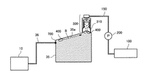
インクカートリッジ10は、供給チューブ36を通じてヘッドタンク35と連通している。ヘッドタンク35の上部には、気泡排出のための本発明における弁手段である弁ユニット300が備えられている。弁ユニット300には、排気流路を形成する排気チューブ150が接続され、排気チューブ150には排気手段である排気ポンプ200を介して廃液タンク152に接続されている。
Next, the ink supply system in the first embodiment of the present invention will be described with reference to the schematic explanatory view of FIG.
The
また、記録ヘッド34のノズル面をキャッピングする吸引キャップ82aが設けられ、記録ヘッド34内のインクを吸引するときは吸引キャップ82aでノズル面をキャピングして吸引キャップ82aに接続された維持回復ポンプ90を駆動してノズルからインクをキャップ82a内に吸引排出させた後、排出チューブ91を介して廃液タンク100に排出する。なお、吸引排出させたインクを廃液タンク100ではなくインクカートリッジ10に戻す構成も採り得る。また、吸引キャップ82a内に空吐出を行う構成も採り得る。
Further, a
また、ワイパ部材83はワイピングユニット92に取り付けられ、このワイパ部材843によってメンテナンス後の記録ヘッド34のノズル面を払拭することで、ノズルメニスカスを整える。
The
ヘッドタンク35と記録ヘッド34の間には、インク中に存在する異物やゴミを取り除き、インクを吐出するノズルを詰まらせない目的で、フィルタ部材109が介装されている。
A
なお、インクカートリッジ10は、インク袋にインクを収容した密閉容器でも良いし、大気連通部を有し、内部を大気に開放している大気開放容器でも良い。
The
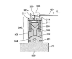
次に、このインク供給系における弁ユニット300の詳細について図4の断面説明図を参照して説明する。
弁ユニット300は、ヘッドタンク35と一体に設けられたハウジング部309内に、ヘッドタンク35内と弁座321との間の流路を開閉する第1の第1の弁体である気泡排出弁310と、気泡排出弁310を開放する方向に付勢する付勢手段である付勢ばね350と、気泡排出弁310が当接する弁座部である弁座321と、排気チューブ150及び排気室365とヘッドタンク35との間の流路となる弁座321の穴321aを開閉し、気泡排出弁310の動作と連動する第2の弁体である開閉弁320から構成される。
Next, details of the
The
気泡排出弁310には、ヘッドタンク35内を排気チューブ150と連通するための連通路305が設けられており、弁座321と当接する箇所に弾性部材からなるシール部311が設けられている。この気泡排出弁310は、図において上下方向に移動可能であり、最下点でストッパ301によって支えられる。そして、気泡排出弁310と開閉弁320とは連結部材319にて連結されることで、気泡排出弁310と開閉弁320とが連動する。
The
なお、排気チューブ150は、図3の場合、気泡排出弁310と直角に配置されている状態で図示しているが、この方向に関わらず気泡が流れやすい方向、例えば、弁座321の上方(垂直方向)に配置されていても良い。また、気泡排出弁310に設けられたシール部311と開閉弁320は、組み立て性を踏まえ、2部品で構成されていることが好ましい。
In the case of FIG. 3, the
次に、このように構成した弁ユニット300による気泡排出動作について図5を参照して説明する。
まず、図5(a)に示すように、ヘッドタンク35の上部(天面部)に滞留した気泡400が気泡排出弁310の下部に集まっている状態にあるとき、排気ポンプ200を正方向に駆動して矢印α方向への流れを発生させると、排気チューブ150及び排気室365の内部が負圧になる。そして、排気チューブ150及び排気室365の内圧が、ヘッドタンク35内部の圧力を下回り、かつ、その圧力差による力が、付勢ばね350の付勢力を上回ると、図5(b)に示すように、気泡排出弁310が上昇し、これに連動して開閉弁320が上昇して開弁する。
Next, the bubble discharging operation by the
First, as shown in FIG. 5A, when the
開閉弁320が開いた直後、大きな圧力差により、気泡400は高い流速で気泡排出弁310の連通路305を通過し、矢印βに示すように、一気に弁座321の穴321aを通過して排気チューブ150に送られる。このとき、空気の粘度は20℃相当で0.018cPであり、水のそれと比べて1/55の粘度である。粘度が小さいと、連通路305を通過するときの抵抗が小さくなるため、圧力の損失は小さい。したがって、気泡400が連通路305を通っても気泡排出弁310は開放状態に保持される。
Immediately after the opening /
そして、ヘッドタンク35内から気泡400が気泡排出弁310の連通路305に流れた後、ヘッドタンク35内にあるインク500が連通路305を流れる。このとき、インクの粘度は水よりも高く、一般的に3.0cP程度である。そのため、インク500が連通路305を流れるときの抵抗は、気泡400の166倍である。気泡400が連通路305を流れた後、連通路305をインク500が流れると、インクの圧力は、気泡排出弁310の下面360にあるインクと比べて相対的に圧力が下がり、両者に圧力差が生じる。
Then, after the
この気泡排出弁310の下面360にあるインクの圧力により、図5(c)に示すように、気泡排出弁310は矢印γ方向から力を受け、上方向(弁座321方向)に移動する。その結果、気泡排出弁310のシール部311が弁座321の穴321aを閉鎖するので、ヘッドタンク35内にあるインク500は不必要に排気チューブ150方向に流れることがなく、気泡排出のために無駄なインク消費を低減できる。
Due to the pressure of the ink on the
そして、排気ポンプ200の駆動を停止すると、付勢ばね350の付勢力により、気泡排出弁310が下降し、これに連動して開閉弁320が弁座321の穴321aを閉じる。開閉弁320が閉じることで、排気チューブ150及び排気室365とヘッドタンク35との間が断絶されるため、排気チューブ105及び排気室365に溜められた気泡が再度ヘッドタンク35に流れ込むことはない。
When the drive of the
この場合、気泡排出弁310が下降するとき、ヘッドタンク35内のインク500が連通路305を通過し、気泡排出弁310と付勢ばね350の間に流れ込む可能性がある。しかし、そのインク500は、弁座321から排気チューブ150へと繋がる流路とは逆方向に流れて貯留されることになるので、気泡400の排気を妨げることはない。
In this case, when the
また、気泡排出弁310の連通路305にインク500が留まった状態で排気ポンプ200を駆動させると、ポンプ200の負圧により、インク500が排気チューブ150の方向に流れようとするが、気泡400の浮力が優先し、排気チューブ150には気泡400が流れる。
Further, when the
なお、気泡排出弁310が下降するときに、ヘッドタンク35内に生じる圧力変動を防ぐために、ヘッドタンク35の少なくとも一側面には可撓性フィルム、あるいは、可撓性フィルムとフィルムを外側に付勢する付勢ばねなどからなるダンパ機能を持つことが好ましい。
In order to prevent pressure fluctuations that occur in the
また、排気ポンプ200の駆動を停止してから、気泡排出弁310が下降するまでは、ヘッドタンク35の圧力変動により記録ヘッド34のノズルからインクが垂れても問題ないような状態、例えば吸引キャップ82aなどにてノズル面をキャッピングしておくことが好ましい。
Also, after the drive of the
ここで、気泡排出弁310は、ヘッドタンク35内部に対向する面(下面360)が連通路305方向に窪んでいる形状であることが好ましい。このような形状とすることで、気泡400を溜めておくことができる。つまり、気泡排出弁310の下面360を窪ませることにより、気泡400を連通路305の入口に滞留させることができ、排気ポンプ200の駆動時に、気泡400を確実に連通路305から排気チューブ150に流すことができる。
Here, it is preferable that the
なお、排気室365、排気チューブ150と気泡排出弁310との間のシールを確実に実行するために、シール部311はエラストマー(弾性体)あることが好ましい。ただし、インクに対する耐性のある材質であることが必要となる。同様に開閉弁320と弁座321の間のシールを高めるために、開閉弁320もエラストマー(弾性体)からなることが好ましい。さらに、連通路305の断面形状は、どのような形状でも良いが、インクが連通路305を通過した際に生じる圧力差で気泡排出弁310を上昇させる力が、ばね350による付勢力を上回るような流路抵抗にしなければならない。
In order to reliably perform the seal between the
また、気泡排出弁310に設ける連通路305は、連通路305内を通る気泡400が浮力により排気チューブ150方向に流れやすい形状であることが好ましい。例えば、図4に示すように、気泡400が上昇する方向に傾斜している構成とすることで、気泡400が排気チューブ150方向に流れ易くなり、排気効率を高めることができる。
Moreover, it is preferable that the
また、排気ポンプ200の吸引流量が大きすぎると、気泡排出弁310が急速に閉鎖し十分な気泡排出を行うことができなくなる。一方、排気ポンプ200の吸引流量が小さすぎると、気泡排出弁310が閉鎖せず、気泡400だけでなくインク500も排気チューブ150に流れてしまうことになる。したがって、排気ポンプ200の吸引流量は、最適な流量を定めておくことが好ましい。
On the other hand, if the suction flow rate of the
また、図5(a)に示すように、排気ポンプ200を駆動していないときにおける弁座321とシール部311との間の距離xは、この距離xが長すぎると、気泡排出弁310が排気チューブ150とヘッドタンク35内の流路を閉鎖するのに時間がかかり、インクが排気チューブ150内に流れ込むことになり、一方、この距離xが短すぎると、気泡排出弁310が即座に閉鎖し、十分な気泡排出が実現できない。したがって、距離xに関しても最適な距離を定めることが好ましい。
In addition, as shown in FIG. 5A, when the distance x between the
また、排気ポンプ200は、気泡排出弁310を動かせるほどの負圧が作れるポンプであることを要するが、チューブポンプのように流路を閉塞するポンプを使用する場合、気泡排出弁310が一度上昇すると、排気チューブ150を閉塞しているため、気泡排出弁310が再度下降しない状況が起こりえる。この状況を防ぐ方法については、次の第2実施形態で説明する。
Further, the
このように、弁手段は、液体タンク内と排気流路側とを連通する連通路を有する第1の弁体と、第1の弁体が開弁する方向に付勢する付勢手段と、第1の弁体が当接する弁座部と、第1の弁体の動作に連動して排気流路を開閉する第2の弁体と、を有し、排気手段が駆動されていないときには、弁手段の第1の弁体は開弁状態を保持し、第2の弁体は閉弁状態を保持し、排気手段が駆動されたときには、第2の弁体が開弁し、第2の弁体が開弁した状態で第1の弁体の連通路に空気が流れても第1の弁体は開弁状態に保持され、液体が第1の弁体の連通路を流れることにより第1の弁体が閉弁状態になり、第2の弁体が開弁状態になる構成とすることで、複雑な制御を要することなく、簡単な構成で、無駄な液体消費を低減しつつ、ヘッドタンク内の気泡を排出できる。 As described above, the valve means includes a first valve body having a communication path communicating the inside of the liquid tank and the exhaust flow path side, a biasing means for biasing in the direction in which the first valve body is opened, And a second valve body that opens and closes the exhaust passage in conjunction with the operation of the first valve body, and when the exhaust means is not driven, The first valve body of the means keeps the valve open state, the second valve body keeps the valve closed state, and when the exhaust means is driven, the second valve body opens and the second valve body Even if air flows through the communication passage of the first valve body in a state where the body is open, the first valve body is held in the valve open state, and the liquid flows through the communication passage of the first valve body, so that the first The valve body is closed, and the second valve body is opened, so that complicated control is not required, and a simple configuration reduces wasteful liquid consumption while reducing the head volume. It can discharge the air bubbles in the click.
次に、本発明の第2実施形態について図6及び図7を参照して説明する。なお、図6は同実施形態における弁ユニット部分の断面説明図、図7は同実施形態における排気ポンプの駆動の説明に供する説明図である。
本実施形態では、排気ポンプ200として停止しているときには閉状態にあるチューブポンプを使用している。前記第1実施形態で説明したように、排気ポンプ200を正方向に駆動(正転駆動)して排気チューブ150から廃液タンク100方向への流れを作用させると、気泡排出弁310が上昇してシール部311が弁座321と当接する。このとき、排気ポンプ200が、チューブポンプのように可逆型ポンプであって、排気チューブ150を常に閉塞するポンプである場合、排気室365及び排気チューブ150内の負圧と、ヘッドタンク35内のインク圧力の圧力差が縮まらないため、気泡排出弁310が下降しない状況が生じる。
Next, a second embodiment of the present invention will be described with reference to FIGS. 6 is a cross-sectional explanatory diagram of the valve unit portion in the same embodiment, and FIG. 7 is an explanatory diagram for explaining the driving of the exhaust pump in the same embodiment.
In the present embodiment, the tube pump in the closed state is used as the
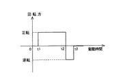
そこで、図7に示すように、排気ポンプ200の動作を制御する。すなわち、時刻t1から時刻t2の間で、排気ポンプ200を正方向に駆動(正転駆動)、すなわち排気室365から廃液タンク100方向に流れる方向に回転して排気動作を行う。時刻t2になったとき、すなわち、排気ポンプ200を停止するときには、まず、正転から逆転(逆方向)に回転方向を変更し、時刻t3まで回転させる。
Therefore, as shown in FIG. 7, the operation of the
このような逆方向への回転動作(逆転駆動)を実施することで、排気室365及び排気チューブ150とヘッドタンク35内のインク間の圧力差を縮めることができ、気泡排出弁310を下降させることができる。
By performing such reverse rotation (reverse drive), the pressure difference between the
なお、排気を確実に行うために、正転時間(t2−t1)は逆転時間(t3−t2)より長くなければならない。また、図7では、時刻t2で正転動作の直後に逆転動作を行っているが、連続的に正転から逆転動作を行うことに限定せず、一定時間待機してから逆転動作に移行するようにしてもよい。 In addition, in order to perform exhaust reliably, the forward rotation time (t2-t1) must be longer than the reverse rotation time (t3-t2). In FIG. 7, the reverse operation is performed immediately after the forward operation at time t2. However, the present invention is not limited to continuously performing the reverse operation from the normal operation. You may do it.
次に、本発明の第3実施形態について図8を参照して説明する。なお、図8は同実施形態における弁ユニット部分をその気泡排出動作とともに説明する断面説明図である。
本実施形態では、気泡排出弁310の連通路305をストレート形状にしている。つまり、前記第1実施形態における気泡排出弁310のように連通路305が途中で分岐する形状にした場合には、作製に手間がかかるほか、コストアップにも繋がる。また、気泡排出弁310が重力方向に向かって長くなる。そこで、気泡排出弁310にストレート形状の連通路305を設けることで、気泡排出弁310の小型化を図っている。
Next, a third embodiment of the present invention will be described with reference to FIG. In addition, FIG. 8 is sectional explanatory drawing explaining the valve unit part in the embodiment with the bubble discharge | emission operation | movement.
In the present embodiment, the
また、ここでは、気泡排出弁310のシール部311が弁座321の凹部370に嵌り込む構成としている。これにより、弁ユニット300全体の高さ方向をより小型にすることができる。
Further, here, the
本実施形態においても、図8(a)に示すように、ヘッドタンク35の上部(天面部)に滞留した気泡400が気泡排出弁310の下部に集まっている状態にあるとき、排気ポンプ200を正方向に駆動して矢印α方向への流れを発生させると、排気チューブ150及び排気室365の内部が負圧になる。そして、排気チューブ150及び排気室365の内圧が、ヘッドタンク35内部の圧力を下回り、かつ、その圧力差による力が、付勢ばね350の付勢力を上回ると、図8(b)に示すように、気泡排出弁310が上昇し、これに連動して開閉弁320が上昇して開弁する。
Also in the present embodiment, as shown in FIG. 8A, when the air bubbles 400 staying in the upper part (top surface part) of the
開閉弁320が開いた直後、大きな圧力差により、気泡400は高い流速で気泡排出弁310の連通路305を通過し、矢印βに示すように、一気に弁座321の穴321aを通過して排気チューブ150に送られる。このとき、気泡400が連通路305を通っても気泡排出弁310は開放状態に保持される。
Immediately after the opening /
そして、ヘッドタンク35内から気泡400が気泡排出弁310の連通路305に流れた後、ヘッドタンク35内にあるインク500が連通路305を流れる。これにより、図8(c)に示すように、気泡排出弁310は下方向から力を受け、上方向(弁座321方向)に移動する。その結果、気泡排出弁310のシール部311が弁座321の穴321aを閉鎖するので、ヘッドタンク35内にあるインク500は不必要に排気チューブ150方向に流れることがなく、気泡排出のために無駄なインク消費を低減できる。
Then, after the
次に、本発明の第4実施形態について図9を参照して説明する。なお、図9は同実施形態における弁ユニット部分をその気泡排出動作とともに説明する断面説明図である。
本実施形態では、前記第3実施形態において、開閉弁320を取り除き、排気ポンプ200として、停止状態で排気チューブ150を常に閉塞する可逆型ポンプとしてのチューブポンプを備えている。開閉弁320がある場合、気泡排出弁310の動作によっては、完全に弁座321と排気チューブ150をシールできないおそれがある。そこで、開閉弁320をなくし、その代わりに、排気ポンプ200としてチューブポンプを使用し、前述した第2実施形態で説明したように、排気動作後に逆回転駆動する構成としている。
Next, a fourth embodiment of the present invention will be described with reference to FIG. FIG. 9 is a cross-sectional explanatory view for explaining the valve unit portion in the same embodiment together with the bubble discharging operation.
In the present embodiment, in the third embodiment, the on-off
すなわち、本実施形態においても、図9(a)に示すように、ヘッドタンク35の上部(天面部)に滞留した気泡400が気泡排出弁310の下部に集まっている状態にあるとき、排気ポンプ200を正転駆動して矢印α方向への流れを発生させると、排気チューブ150及び排気室365の内部が負圧になるので、気泡400は高い流速で気泡排出弁310の連通路305を通過し、弁座321の穴321aを通過して排気チューブ150に送られる。このとき、気泡400が連通路305を通っても気泡排出弁310は開放状態に保持される。
That is, also in this embodiment, as shown in FIG. 9A, when the
そして、ヘッドタンク35内から気泡400が気泡排出弁310の連通路305に流れた後、ヘッドタンク35内にあるインク500が連通路305を流れる。これにより、図9(b)に示すように、気泡排出弁310は下方向から力を受け、上方向(弁座321方向)に移動する。その結果、気泡排出弁310のシール部311が弁座321の穴321aを閉鎖するので、ヘッドタンク35内にあるインク500は不必要に排気チューブ150方向に流れることがなく、気泡排出のために無駄なインク消費を低減できる。
Then, after the
そして、その後、排気ポンプ200の正転駆動から逆転駆動に切り替えることで、排気室365及び排気チューブ150とヘッドタンク35内のインク間の圧力差を縮まり、気泡排出弁310が付勢ばね350の付勢力で下降する。
Then, the pressure difference between the ink in the
このように構成することで、弁座321と排気チューブ150とのシールを考慮する必要が無く、更に開閉弁320がないために、組立性の向上が図れる。ただし、排気ポンプ200は、例えばチューブポンプのように必ず排気チューブ150を常に閉塞するポンプでなければならず、排気動作が終了後には、逆回転して、気泡排出弁310を下降させる必要がある。
By configuring in this way, it is not necessary to consider the seal between the
このように、弁手段は、液体タンク内と排気流路側とを連通する連通路を有する第1の弁体と、第1の弁体が開弁する方向に付勢する付勢手段と、第1の弁体が当接する弁座部と、を有し、排気手段が駆動されていないときには、弁手段の第1の弁体は開弁状態を保持し、排気手段が正転駆動されたときには、第1の弁体の連通路に空気が流れても第1の弁体は開弁状態に保持され、液体が第1の弁体の連通路を流れることにより第1の弁体が閉弁状態になり、排気手段は、第1の弁体が閉弁状態になった後、逆転駆動された後に停止される構成とすることで、複雑な制御を要することなく、簡単な構成で、無駄な液体消費を低減しつつ、ヘッドタンク内の気泡を排出できる。 As described above, the valve means includes a first valve body having a communication path communicating the inside of the liquid tank and the exhaust flow path side, a biasing means for biasing in the direction in which the first valve body is opened, The first valve body of the valve means is kept open when the exhaust means is not driven, and when the exhaust means is normally driven. Even if air flows through the communication path of the first valve body, the first valve body is held in the open state, and the liquid flows through the communication path of the first valve body, thereby closing the first valve body. The exhaust means is configured to be stopped after being driven in reverse rotation after the first valve body is closed, so that no complicated control is required, and a simple configuration is used. Air bubbles in the head tank can be discharged while reducing liquid consumption.
次に、本発明の第5実施形態について図10を参照して説明する。なお、図10は同実施形態における弁ユニット部分をその気泡排出動作とともに説明する断面説明図である。
本実施形態は、排気室365内にてこ機構(てこ部材)を備えている。すなわち、排気室365内には支点480を中心として揺動するてこ部材450が配設され、てこ部材450の一端側は弁座321の穴321aを介して気泡排出弁310のシール部311に対向し、他端側には排気室365の排気チューブ150との接続部分である開口440を開閉する開閉弁410が設けられている。
Next, a fifth embodiment of the present invention will be described with reference to FIG. In addition, FIG. 10 is sectional explanatory drawing explaining the valve unit part in the embodiment with the bubble discharge | emission operation | movement.
In the present embodiment, a lever mechanism (lever member) is provided in the
そして、図10(a)に示す気泡排出前の状態から排気ポンプ200を駆動すると、気泡400は排気室365、排気チューブ150を通過して排気される。その後、図10(b)に示すようにインク500が連通路305を通過すると、ヘッドタンク35内のインク圧力と排気室365内の圧力差により、気泡排出弁310が上昇する。このとき、てこ450が支点480を中心に回転する。そして気泡排出弁310が更に上昇すると、ある点で、開閉弁410が排気チューブ150への開口部440を閉塞する。これにより、インクを排気チューブ150内に流さず、気泡400を排気することができる。
When the
なお、てこ比は、気泡排出弁310側を大きくすると閉弁するための力を得ることができ、開閉弁410と排気チューブ150間の確実なシールを実現することができる。また、排気ポンプ200に、例えばチューブポンプのような排気チューブ150を常に閉塞するポンプを使用した場合、開閉弁410が閉塞した後に、逆回転させて、気泡排出弁310を下降させる必要がある。
Note that the lever ratio can obtain a force for closing the valve when the
次に、本発明の第6実施形態について図11を参照して説明する。なお、図11は同実施形態における弁ユニット部分の断面説明図である。
本実施形態では、ヘッドタンク35から弁ユニット300に通じる流路600を弁ユニット300側に向かって先細る形状にしている。
Next, a sixth embodiment of the present invention will be described with reference to FIG. In addition, FIG. 11 is sectional explanatory drawing of the valve unit part in the embodiment.
In the present embodiment, the
つまり、本発明では、気泡400は気泡排出弁310の下部に集まっている方が一回の排気動作において排気でき、排気効率を高めることができる。そこで、ヘッドタンク35と弁ユニット300間の流路600を先細りにしておくことで、気泡400が浮力により上昇するときにに、矢印Aに示すように、気泡排出弁310の下部に自動的に集まるようにすることができる。なお、先細りの形状は、図11に示す曲面形状に限定されるものではなく、テーパ形状であっても良いし、気泡400が上昇するときにその先が絞られる形状であればどのような形状でもよい。
That is, in the present invention, the
次に、本発明の第7実施形態について図12を参照して説明する。なお、図12は同実施形態におけるインク供給系を含むヘッドタンク部分の断面説明図を参照して説明する。
本実施形態では、ヘッドタンク35の天面35aを弁ユニット300方向に向けて(斜め上方に向けて)傾斜させている。
Next, a seventh embodiment of the present invention will be described with reference to FIG. FIG. 12 is described with reference to a cross-sectional explanatory view of a head tank portion including an ink supply system in the same embodiment.
In the present embodiment, the
これにより、インクカートリッジ10の交換に伴って供給チューブ36内に混入した気泡400や供給チューブ36を透過した空気による気泡400は、浮力によって矢印B方向に移動する。移動した気泡400は、弁ユニット300の下部に集まるため、一回の排気動作における排気効率を高めることができる。なお、ヘッドタンク35の傾斜は、供給チューブ36とヘッドタンク35との連結部700を基準に弁ユニット300に向けて上方に傾いていることが好ましい。
As a result, the
なお、上記実施形態では本発明をシリアル型画像形成装置に適用した例で説明しているが、ライン型画像形成装置にも適用することができる。 In the above embodiment, the present invention is described as an example in which the present invention is applied to a serial type image forming apparatus. However, the present invention can also be applied to a line type image forming apparatus.
10 インクカートリッジ
33 キャリッジ
34、34a、34b 記録ヘッド(液体吐出ヘッド)
35 ヘッドタンク(液体タンク)
81 維持回復機構
100 廃液タンク
150 排気チューブ
200 排気ポンプ
300 弁ユニット(弁手段)
305 連津路
310 排気制御弁(第1の弁体)
320 開閉弁(第2の弁体)
321 弁座
365 排気室
450 てこ部材
10
35 Head tank (liquid tank)
81 Maintenance and
305
320 On-off valve (second valve element)
321
Claims (10)
前記記録ヘッドに供給する液体を貯留する液体タンクと、
前記液体の廃棄を貯留する廃液タンクと、
前記液体タンクの天面部分を開閉する弁手段と、
前記弁手段と前記廃液タンクを連通する排気流路と、
前記排気流路に設けられ、前記液体タンク側から前記廃液タンク側に流体を送る排気手段と、を備え、
前記弁手段は、
前記液体タンク内と前記排気流路側とを連通する連通路を有する第1の弁体と、
前記第1の弁体が開弁する方向に付勢する付勢手段と、
前記第1の弁体が当接する弁座部と、
前記第1の弁体の動作に連動して前記排気流路を開閉する第2の弁体と、を有し、
前記排気手段が駆動されていないときには、前記弁手段の前記第1の弁体は開弁状態を保持し、前記第2の弁体は閉弁状態を保持し、
前記排気手段が駆動されたときには、前記第2の弁体が開弁し、前記第2の弁体が開弁した状態で前記第1の弁体の前記連通路に空気が流れても前記第1の弁体は開弁状態に保持され、前記液体が前記第1の弁体の前記連通路を流れることにより前記第1の弁体が閉弁状態になり、前記第2の弁体が開弁状態になる
ことを特徴とする画像形成装置。 A recording head having nozzles for discharging droplets;
A liquid tank for storing liquid to be supplied to the recording head;
A waste liquid tank for storing the liquid waste;
Valve means for opening and closing the top surface portion of the liquid tank;
An exhaust passage communicating the valve means and the waste liquid tank;
An exhaust means provided in the exhaust flow path for sending fluid from the liquid tank side to the waste liquid tank side,
The valve means includes
A first valve body having a communication passage communicating the inside of the liquid tank and the exhaust passage side;
Biasing means for biasing the first valve body in a direction to open the valve;
A valve seat against which the first valve body abuts;
A second valve body that opens and closes the exhaust passage in conjunction with the operation of the first valve body,
When the exhaust means is not driven, the first valve body of the valve means keeps the valve open state, the second valve body keeps the valve closed state,
When the exhaust means is driven, the second valve body is opened, and the second valve body is opened and air flows into the communication passage of the first valve body with the second valve body opened. The first valve body is held in an open state, and the liquid flows through the communication passage of the first valve body, whereby the first valve body is closed and the second valve body is opened. An image forming apparatus that is in a valve state.
前記排気手段を正転駆動して前記液体タンク側から前記廃液タンク側に流体を送った後に停止させるときには、前記排気手段を逆転駆動した後に停止させる
ことを特徴とする請求項1に記載の画像形成装置。 The exhaust means is a reversible exhaust means for closing the exhaust passage in a stopped state,
2. The image according to claim 1, wherein when the exhaust unit is driven to rotate forward and stopped after the fluid is sent from the liquid tank side to the waste liquid tank side, the exhaust unit is stopped after being driven reversely. 3. Forming equipment.
前記てこ部材の一端側は前記第1の弁体に臨み、他端側には前記第2の弁体が設けられている
ことを特徴とする請求項1又は2に記載の画像形成装置。 A lever member is disposed between the first valve body and the second valve body,
The image forming apparatus according to claim 1, wherein one end side of the lever member faces the first valve body, and the second valve body is provided on the other end side.
前記記録ヘッドに供給する液体を貯留する液体タンクと、
前記液体の廃棄を貯留する廃液タンクと、
前記液体タンクの天面部分を開閉する弁手段と、
前記弁手段と前記廃液タンクを連通する排気流路と、
前記排気流路に設けられ、前記液体タンク側から前記廃液タンク側に流体を送る排気手段と、を備え、
前記排気手段は、停止状態では前記排気流路を閉塞する可逆型排気手段であり、
前記弁手段は、
前記液体タンク内と前記排気流路側とを連通する連通路を有する第1の弁体と、
前記第1の弁体が開弁する方向に付勢する付勢手段と、
前記第1の弁体が当接する弁座部と、を有し、
前記排気手段が駆動されていないときには、前記弁手段の前記第1の弁体は開弁状態を保持し、前記排気手段が正転駆動されたときには、前記第1の弁体の前記連通路に空気が流れても前記第1の弁体は開弁状態に保持され、前記液体が前記第1の弁体の前記連通路を流れることにより前記第1の弁体が閉弁状態になり、
前記排気手段は、前記第1の弁体が閉弁状態になった後、逆転駆動された後に停止される
ことを特徴とする画像形成装置。 A recording head having nozzles for discharging droplets;
A liquid tank for storing liquid to be supplied to the recording head;
A waste liquid tank for storing the liquid waste;
Valve means for opening and closing the top surface portion of the liquid tank;
An exhaust passage communicating the valve means and the waste liquid tank;
An exhaust means provided in the exhaust flow path for sending fluid from the liquid tank side to the waste liquid tank side,
The exhaust means is a reversible exhaust means for closing the exhaust passage in a stopped state,
The valve means includes
A first valve body having a communication passage communicating the inside of the liquid tank and the exhaust passage side;
Biasing means for biasing the first valve body in a direction to open the valve;
A valve seat against which the first valve body abuts,
When the exhaust means is not driven, the first valve body of the valve means is kept open, and when the exhaust means is driven to rotate forward, the first valve body is connected to the communication path of the first valve body. Even if air flows, the first valve body is held in an open state, and the liquid flows through the communication path of the first valve body, whereby the first valve body is in a closed state,
The image forming apparatus according to claim 1, wherein the exhaust unit is stopped after the first valve body is in a closed state and then reversely driven.
Priority Applications (2)
| Application Number | Priority Date | Filing Date | Title |
|---|---|---|---|
| JP2011058908A JP5664373B2 (en) | 2011-03-17 | 2011-03-17 | Image forming apparatus |
| US13/416,066 US8506066B2 (en) | 2011-03-17 | 2012-03-09 | Image forming apparatus |
Applications Claiming Priority (1)
| Application Number | Priority Date | Filing Date | Title |
|---|---|---|---|
| JP2011058908A JP5664373B2 (en) | 2011-03-17 | 2011-03-17 | Image forming apparatus |
Publications (2)
| Publication Number | Publication Date |
|---|---|
| JP2012192643A true JP2012192643A (en) | 2012-10-11 |
| JP5664373B2 JP5664373B2 (en) | 2015-02-04 |
Family
ID=46828109
Family Applications (1)
| Application Number | Title | Priority Date | Filing Date |
|---|---|---|---|
| JP2011058908A Expired - Fee Related JP5664373B2 (en) | 2011-03-17 | 2011-03-17 | Image forming apparatus |
Country Status (2)
| Country | Link |
|---|---|
| US (1) | US8506066B2 (en) |
| JP (1) | JP5664373B2 (en) |
Cited By (2)
| Publication number | Priority date | Publication date | Assignee | Title |
|---|---|---|---|---|
| JP2015066828A (en) * | 2013-09-30 | 2015-04-13 | ブラザー工業株式会社 | Liquid discharge device |
| CN110774750A (en) * | 2019-11-05 | 2020-02-11 | 杭州晁松科技有限公司 | Automatic paper floating equipment of printing machine |
Families Citing this family (4)
| Publication number | Priority date | Publication date | Assignee | Title |
|---|---|---|---|---|
| JP6119261B2 (en) | 2013-01-18 | 2017-04-26 | 株式会社リコー | Image forming apparatus |
| JP6256804B2 (en) | 2013-12-03 | 2018-01-10 | 株式会社リコー | Liquid supply apparatus, droplet discharge apparatus, and image forming apparatus |
| JP2017077652A (en) * | 2015-10-20 | 2017-04-27 | セイコーエプソン株式会社 | Tank, tank unit, liquid jet system and liquid jet device |
| JP6922258B2 (en) * | 2017-03-02 | 2021-08-18 | セイコーエプソン株式会社 | Ink replenishment container and ink replenishment system |
Citations (15)
| Publication number | Priority date | Publication date | Assignee | Title |
|---|---|---|---|---|
| US10023A (en) * | 1853-09-20 | Machine fob sawing sticks eob broom-handles | ||
| JPH0481606U (en) * | 1990-11-27 | 1992-07-16 | ||
| JPH11320901A (en) * | 1998-05-12 | 1999-11-24 | Canon Inc | Ink-jet recording apparatus |
| JP2000140508A (en) * | 1998-11-13 | 2000-05-23 | Nippon Mitsubishi Oil Corp | Air bubble removing system |
| JP2001155985A (en) * | 1999-11-25 | 2001-06-08 | Nec Kyushu Ltd | Filter apparatus and resist coating apparatus |
| JP2005169892A (en) * | 2003-12-12 | 2005-06-30 | Brother Ind Ltd | Inkjet printer |
| JP2009126086A (en) * | 2007-11-26 | 2009-06-11 | Canon Inc | Fluid discharge device and recording head |
| JP2009248412A (en) * | 2008-04-04 | 2009-10-29 | Canon Finetech Inc | Inkjet recorder |
| JP2010120340A (en) * | 2008-11-21 | 2010-06-03 | Canon Inc | Fluid discharging device and recording device |
| JP2010221470A (en) * | 2009-03-23 | 2010-10-07 | Brother Ind Ltd | Liquid container |
| JP2010280188A (en) * | 2009-06-06 | 2010-12-16 | Ricoh Co Ltd | Image forming apparatus |
| JP2010284875A (en) * | 2009-06-11 | 2010-12-24 | Canon Inc | Bubble discharge device and inkjet recording apparatus with the same |
| JP2011025565A (en) * | 2009-07-27 | 2011-02-10 | Ricoh Co Ltd | Image forming apparatus |
| JP2011110870A (en) * | 2009-11-27 | 2011-06-09 | Ricoh Co Ltd | Image forming apparatus |
| JP2013141781A (en) * | 2012-01-11 | 2013-07-22 | Ricoh Co Ltd | Image forming apparatus |
Family Cites Families (15)
| Publication number | Priority date | Publication date | Assignee | Title |
|---|---|---|---|---|
| US2684684A (en) * | 1951-08-30 | 1954-07-27 | Anco Inc | Automatic air bleeder valve for hydraulic systems |
| US2729228A (en) * | 1952-04-01 | 1956-01-03 | Anco Inc | Automatic air bleeder valve for hydraulic systems |
| US2908282A (en) * | 1957-02-26 | 1959-10-13 | Maisch Oliver | Automatic vent valve |
| US4329696A (en) * | 1980-07-23 | 1982-05-11 | The Mead Corporation | Ink jet fluid system |
| US4524793A (en) * | 1983-10-14 | 1985-06-25 | Pall Corporation | Automatic reservoir bleed valve |
| US4813446A (en) * | 1987-04-06 | 1989-03-21 | Pall Corporation | Automatic pressurized reservoir bleed valve |
| GB9111327D0 (en) * | 1991-05-24 | 1991-07-17 | Pall Corp | Automatic bleed valves |
| US5305793A (en) * | 1992-09-16 | 1994-04-26 | Pall Corporation | Automatic pressurized reservoir bleed valve |
| JP3684022B2 (en) * | 1996-04-25 | 2005-08-17 | キヤノン株式会社 | Liquid replenishment method, liquid discharge recording apparatus, and ink tank used as a main tank of the liquid discharge recording apparatus |
| WO2009096965A1 (en) * | 2008-01-31 | 2009-08-06 | Hewlett-Packard Development Company, L.P. | Apparatus and methods for purging air from a fluid conveying tube |
| JP5121583B2 (en) | 2008-06-02 | 2013-01-16 | 株式会社リコー | Droplet ejection device, image forming apparatus |
| JP5299179B2 (en) | 2009-09-02 | 2013-09-25 | 株式会社リコー | Image forming apparatus |
| JP5509822B2 (en) | 2009-12-07 | 2014-06-04 | 株式会社リコー | Image forming apparatus |
| JP5381678B2 (en) | 2009-12-15 | 2014-01-08 | 株式会社リコー | Image forming apparatus |
| JP5488314B2 (en) | 2010-08-03 | 2014-05-14 | 株式会社リコー | Image forming apparatus |
-
2011
- 2011-03-17 JP JP2011058908A patent/JP5664373B2/en not_active Expired - Fee Related
-
2012
- 2012-03-09 US US13/416,066 patent/US8506066B2/en not_active Expired - Fee Related
Patent Citations (15)
| Publication number | Priority date | Publication date | Assignee | Title |
|---|---|---|---|---|
| US10023A (en) * | 1853-09-20 | Machine fob sawing sticks eob broom-handles | ||
| JPH0481606U (en) * | 1990-11-27 | 1992-07-16 | ||
| JPH11320901A (en) * | 1998-05-12 | 1999-11-24 | Canon Inc | Ink-jet recording apparatus |
| JP2000140508A (en) * | 1998-11-13 | 2000-05-23 | Nippon Mitsubishi Oil Corp | Air bubble removing system |
| JP2001155985A (en) * | 1999-11-25 | 2001-06-08 | Nec Kyushu Ltd | Filter apparatus and resist coating apparatus |
| JP2005169892A (en) * | 2003-12-12 | 2005-06-30 | Brother Ind Ltd | Inkjet printer |
| JP2009126086A (en) * | 2007-11-26 | 2009-06-11 | Canon Inc | Fluid discharge device and recording head |
| JP2009248412A (en) * | 2008-04-04 | 2009-10-29 | Canon Finetech Inc | Inkjet recorder |
| JP2010120340A (en) * | 2008-11-21 | 2010-06-03 | Canon Inc | Fluid discharging device and recording device |
| JP2010221470A (en) * | 2009-03-23 | 2010-10-07 | Brother Ind Ltd | Liquid container |
| JP2010280188A (en) * | 2009-06-06 | 2010-12-16 | Ricoh Co Ltd | Image forming apparatus |
| JP2010284875A (en) * | 2009-06-11 | 2010-12-24 | Canon Inc | Bubble discharge device and inkjet recording apparatus with the same |
| JP2011025565A (en) * | 2009-07-27 | 2011-02-10 | Ricoh Co Ltd | Image forming apparatus |
| JP2011110870A (en) * | 2009-11-27 | 2011-06-09 | Ricoh Co Ltd | Image forming apparatus |
| JP2013141781A (en) * | 2012-01-11 | 2013-07-22 | Ricoh Co Ltd | Image forming apparatus |
Cited By (2)
| Publication number | Priority date | Publication date | Assignee | Title |
|---|---|---|---|---|
| JP2015066828A (en) * | 2013-09-30 | 2015-04-13 | ブラザー工業株式会社 | Liquid discharge device |
| CN110774750A (en) * | 2019-11-05 | 2020-02-11 | 杭州晁松科技有限公司 | Automatic paper floating equipment of printing machine |
Also Published As
| Publication number | Publication date |
|---|---|
| US8506066B2 (en) | 2013-08-13 |
| US20120236072A1 (en) | 2012-09-20 |
| JP5664373B2 (en) | 2015-02-04 |
Similar Documents
| Publication | Publication Date | Title |
|---|---|---|
| JP4841467B2 (en) | Image forming apparatus | |
| JP5169041B2 (en) | Liquid ejection head unit and image forming apparatus | |
| JP4880564B2 (en) | Liquid container and image forming apparatus | |
| JP4841349B2 (en) | Liquid ejection head unit and image forming apparatus | |
| JP5664373B2 (en) | Image forming apparatus | |
| JP5445025B2 (en) | Image forming apparatus | |
| JP5995184B2 (en) | Image forming apparatus | |
| JP5516248B2 (en) | Liquid container and image forming apparatus | |
| JP6314632B2 (en) | Image forming apparatus | |
| JP5321969B2 (en) | Image forming apparatus | |
| JP2009286033A (en) | Liquid supply device and image forming apparatus | |
| JP6119284B2 (en) | Image forming apparatus | |
| JP5703721B2 (en) | Image forming apparatus | |
| JP5754621B2 (en) | Image forming apparatus | |
| JP5354197B2 (en) | Ink cartridge and image forming apparatus provided with the same | |
| JP2008183746A (en) | Liquid supply device and image forming device | |
| JP2013059899A (en) | Image forming apparatus | |
| JP5309939B2 (en) | Liquid ejecting apparatus and image forming apparatus | |
| JP2014050989A (en) | Image formation device | |
| JP2012051277A (en) | Image forming apparatus | |
| JP5803459B2 (en) | Image forming apparatus | |
| JP5994309B2 (en) | Image forming apparatus, liquid cartridge | |
| JP2012192642A (en) | Image forming apparatus and head tank | |
| JP2010208098A (en) | Liquid container and image forming apparatus | |
| JP5862049B2 (en) | Image forming apparatus |
Legal Events
| Date | Code | Title | Description |
|---|---|---|---|
| A621 | Written request for application examination |
Free format text: JAPANESE INTERMEDIATE CODE: A621 Effective date: 20140214 |
|
| A977 | Report on retrieval |
Free format text: JAPANESE INTERMEDIATE CODE: A971007 Effective date: 20140918 |
|
| A131 | Notification of reasons for refusal |
Free format text: JAPANESE INTERMEDIATE CODE: A131 Effective date: 20140930 |
|
| A521 | Written amendment |
Free format text: JAPANESE INTERMEDIATE CODE: A523 Effective date: 20141021 |
|
| TRDD | Decision of grant or rejection written | ||
| A01 | Written decision to grant a patent or to grant a registration (utility model) |
Free format text: JAPANESE INTERMEDIATE CODE: A01 Effective date: 20141111 |
|
| A61 | First payment of annual fees (during grant procedure) |
Free format text: JAPANESE INTERMEDIATE CODE: A61 Effective date: 20141124 |
|
| R151 | Written notification of patent or utility model registration |
Ref document number: 5664373 Country of ref document: JP Free format text: JAPANESE INTERMEDIATE CODE: R151 |
|
| LAPS | Cancellation because of no payment of annual fees |