JP2012191785A - Battery charge control device - Google Patents
Battery charge control device Download PDFInfo
- Publication number
- JP2012191785A JP2012191785A JP2011054094A JP2011054094A JP2012191785A JP 2012191785 A JP2012191785 A JP 2012191785A JP 2011054094 A JP2011054094 A JP 2011054094A JP 2011054094 A JP2011054094 A JP 2011054094A JP 2012191785 A JP2012191785 A JP 2012191785A
- Authority
- JP
- Japan
- Prior art keywords
- battery
- charge
- charging
- power
- soc
- Prior art date
- Legal status (The legal status is an assumption and is not a legal conclusion. Google has not performed a legal analysis and makes no representation as to the accuracy of the status listed.)
- Granted
Links
Images


Classifications
-
- H—ELECTRICITY
- H02—GENERATION; CONVERSION OR DISTRIBUTION OF ELECTRIC POWER
- H02J—CIRCUIT ARRANGEMENTS OR SYSTEMS FOR SUPPLYING OR DISTRIBUTING ELECTRIC POWER; SYSTEMS FOR STORING ELECTRIC ENERGY
- H02J7/00—Circuit arrangements for charging or depolarising batteries or for supplying loads from batteries
- H02J7/007—Regulation of charging or discharging current or voltage
- H02J7/007188—Regulation of charging or discharging current or voltage the charge cycle being controlled or terminated in response to non-electric parameters
- H02J7/007192—Regulation of charging or discharging current or voltage the charge cycle being controlled or terminated in response to non-electric parameters in response to temperature
- H02J7/007194—Regulation of charging or discharging current or voltage the charge cycle being controlled or terminated in response to non-electric parameters in response to temperature of the battery
-
- B—PERFORMING OPERATIONS; TRANSPORTING
- B60—VEHICLES IN GENERAL
- B60L—PROPULSION OF ELECTRICALLY-PROPELLED VEHICLES; SUPPLYING ELECTRIC POWER FOR AUXILIARY EQUIPMENT OF ELECTRICALLY-PROPELLED VEHICLES; ELECTRODYNAMIC BRAKE SYSTEMS FOR VEHICLES IN GENERAL; MAGNETIC SUSPENSION OR LEVITATION FOR VEHICLES; MONITORING OPERATING VARIABLES OF ELECTRICALLY-PROPELLED VEHICLES; ELECTRIC SAFETY DEVICES FOR ELECTRICALLY-PROPELLED VEHICLES
- B60L53/00—Methods of charging batteries, specially adapted for electric vehicles; Charging stations or on-board charging equipment therefor; Exchange of energy storage elements in electric vehicles
- B60L53/60—Monitoring or controlling charging stations
- B60L53/64—Optimising energy costs, e.g. responding to electricity rates
-
- B—PERFORMING OPERATIONS; TRANSPORTING
- B60—VEHICLES IN GENERAL
- B60L—PROPULSION OF ELECTRICALLY-PROPELLED VEHICLES; SUPPLYING ELECTRIC POWER FOR AUXILIARY EQUIPMENT OF ELECTRICALLY-PROPELLED VEHICLES; ELECTRODYNAMIC BRAKE SYSTEMS FOR VEHICLES IN GENERAL; MAGNETIC SUSPENSION OR LEVITATION FOR VEHICLES; MONITORING OPERATING VARIABLES OF ELECTRICALLY-PROPELLED VEHICLES; ELECTRIC SAFETY DEVICES FOR ELECTRICALLY-PROPELLED VEHICLES
- B60L58/00—Methods or circuit arrangements for monitoring or controlling batteries or fuel cells, specially adapted for electric vehicles
- B60L58/10—Methods or circuit arrangements for monitoring or controlling batteries or fuel cells, specially adapted for electric vehicles for monitoring or controlling batteries
- B60L58/12—Methods or circuit arrangements for monitoring or controlling batteries or fuel cells, specially adapted for electric vehicles for monitoring or controlling batteries responding to state of charge [SoC]
-
- B—PERFORMING OPERATIONS; TRANSPORTING
- B60—VEHICLES IN GENERAL
- B60L—PROPULSION OF ELECTRICALLY-PROPELLED VEHICLES; SUPPLYING ELECTRIC POWER FOR AUXILIARY EQUIPMENT OF ELECTRICALLY-PROPELLED VEHICLES; ELECTRODYNAMIC BRAKE SYSTEMS FOR VEHICLES IN GENERAL; MAGNETIC SUSPENSION OR LEVITATION FOR VEHICLES; MONITORING OPERATING VARIABLES OF ELECTRICALLY-PROPELLED VEHICLES; ELECTRIC SAFETY DEVICES FOR ELECTRICALLY-PROPELLED VEHICLES
- B60L58/00—Methods or circuit arrangements for monitoring or controlling batteries or fuel cells, specially adapted for electric vehicles
- B60L58/10—Methods or circuit arrangements for monitoring or controlling batteries or fuel cells, specially adapted for electric vehicles for monitoring or controlling batteries
- B60L58/24—Methods or circuit arrangements for monitoring or controlling batteries or fuel cells, specially adapted for electric vehicles for monitoring or controlling batteries for controlling the temperature of batteries
- B60L58/27—Methods or circuit arrangements for monitoring or controlling batteries or fuel cells, specially adapted for electric vehicles for monitoring or controlling batteries for controlling the temperature of batteries by heating
-
- B—PERFORMING OPERATIONS; TRANSPORTING
- B60—VEHICLES IN GENERAL
- B60R—VEHICLES, VEHICLE FITTINGS, OR VEHICLE PARTS, NOT OTHERWISE PROVIDED FOR
- B60R16/00—Electric or fluid circuits specially adapted for vehicles and not otherwise provided for; Arrangement of elements of electric or fluid circuits specially adapted for vehicles and not otherwise provided for
- B60R16/02—Electric or fluid circuits specially adapted for vehicles and not otherwise provided for; Arrangement of elements of electric or fluid circuits specially adapted for vehicles and not otherwise provided for electric constitutive elements
- B60R16/03—Electric or fluid circuits specially adapted for vehicles and not otherwise provided for; Arrangement of elements of electric or fluid circuits specially adapted for vehicles and not otherwise provided for electric constitutive elements for supply of electrical power to vehicle subsystems or for
- B60R16/033—Electric or fluid circuits specially adapted for vehicles and not otherwise provided for; Arrangement of elements of electric or fluid circuits specially adapted for vehicles and not otherwise provided for electric constitutive elements for supply of electrical power to vehicle subsystems or for characterised by the use of electrical cells or batteries
-
- H—ELECTRICITY
- H01—ELECTRIC ELEMENTS
- H01M—PROCESSES OR MEANS, e.g. BATTERIES, FOR THE DIRECT CONVERSION OF CHEMICAL ENERGY INTO ELECTRICAL ENERGY
- H01M10/00—Secondary cells; Manufacture thereof
- H01M10/42—Methods or arrangements for servicing or maintenance of secondary cells or secondary half-cells
- H01M10/44—Methods for charging or discharging
- H01M10/443—Methods for charging or discharging in response to temperature
-
- H—ELECTRICITY
- H01—ELECTRIC ELEMENTS
- H01M—PROCESSES OR MEANS, e.g. BATTERIES, FOR THE DIRECT CONVERSION OF CHEMICAL ENERGY INTO ELECTRICAL ENERGY
- H01M10/00—Secondary cells; Manufacture thereof
- H01M10/42—Methods or arrangements for servicing or maintenance of secondary cells or secondary half-cells
- H01M10/48—Accumulators combined with arrangements for measuring, testing or indicating the condition of cells, e.g. the level or density of the electrolyte
- H01M10/486—Accumulators combined with arrangements for measuring, testing or indicating the condition of cells, e.g. the level or density of the electrolyte for measuring temperature
-
- H—ELECTRICITY
- H01—ELECTRIC ELEMENTS
- H01M—PROCESSES OR MEANS, e.g. BATTERIES, FOR THE DIRECT CONVERSION OF CHEMICAL ENERGY INTO ELECTRICAL ENERGY
- H01M10/00—Secondary cells; Manufacture thereof
- H01M10/60—Heating or cooling; Temperature control
- H01M10/61—Types of temperature control
- H01M10/615—Heating or keeping warm
-
- H—ELECTRICITY
- H01—ELECTRIC ELEMENTS
- H01M—PROCESSES OR MEANS, e.g. BATTERIES, FOR THE DIRECT CONVERSION OF CHEMICAL ENERGY INTO ELECTRICAL ENERGY
- H01M10/00—Secondary cells; Manufacture thereof
- H01M10/60—Heating or cooling; Temperature control
- H01M10/62—Heating or cooling; Temperature control specially adapted for specific applications
- H01M10/625—Vehicles
-
- H—ELECTRICITY
- H01—ELECTRIC ELEMENTS
- H01M—PROCESSES OR MEANS, e.g. BATTERIES, FOR THE DIRECT CONVERSION OF CHEMICAL ENERGY INTO ELECTRICAL ENERGY
- H01M10/00—Secondary cells; Manufacture thereof
- H01M10/60—Heating or cooling; Temperature control
- H01M10/63—Control systems
- H01M10/633—Control systems characterised by algorithms, flow charts, software details or the like
-
- H—ELECTRICITY
- H01—ELECTRIC ELEMENTS
- H01M—PROCESSES OR MEANS, e.g. BATTERIES, FOR THE DIRECT CONVERSION OF CHEMICAL ENERGY INTO ELECTRICAL ENERGY
- H01M10/00—Secondary cells; Manufacture thereof
- H01M10/60—Heating or cooling; Temperature control
- H01M10/65—Means for temperature control structurally associated with the cells
- H01M10/657—Means for temperature control structurally associated with the cells by electric or electromagnetic means
-
- H—ELECTRICITY
- H02—GENERATION; CONVERSION OR DISTRIBUTION OF ELECTRIC POWER
- H02J—CIRCUIT ARRANGEMENTS OR SYSTEMS FOR SUPPLYING OR DISTRIBUTING ELECTRIC POWER; SYSTEMS FOR STORING ELECTRIC ENERGY
- H02J7/00—Circuit arrangements for charging or depolarising batteries or for supplying loads from batteries
- H02J7/007—Regulation of charging or discharging current or voltage
- H02J7/0071—Regulation of charging or discharging current or voltage with a programmable schedule
-
- H—ELECTRICITY
- H02—GENERATION; CONVERSION OR DISTRIBUTION OF ELECTRIC POWER
- H02J—CIRCUIT ARRANGEMENTS OR SYSTEMS FOR SUPPLYING OR DISTRIBUTING ELECTRIC POWER; SYSTEMS FOR STORING ELECTRIC ENERGY
- H02J7/00—Circuit arrangements for charging or depolarising batteries or for supplying loads from batteries
- H02J7/02—Circuit arrangements for charging or depolarising batteries or for supplying loads from batteries for charging batteries from ac mains by converters
- H02J7/04—Regulation of charging current or voltage
-
- B—PERFORMING OPERATIONS; TRANSPORTING
- B60—VEHICLES IN GENERAL
- B60L—PROPULSION OF ELECTRICALLY-PROPELLED VEHICLES; SUPPLYING ELECTRIC POWER FOR AUXILIARY EQUIPMENT OF ELECTRICALLY-PROPELLED VEHICLES; ELECTRODYNAMIC BRAKE SYSTEMS FOR VEHICLES IN GENERAL; MAGNETIC SUSPENSION OR LEVITATION FOR VEHICLES; MONITORING OPERATING VARIABLES OF ELECTRICALLY-PROPELLED VEHICLES; ELECTRIC SAFETY DEVICES FOR ELECTRICALLY-PROPELLED VEHICLES
- B60L2240/00—Control parameters of input or output; Target parameters
- B60L2240/40—Drive Train control parameters
- B60L2240/54—Drive Train control parameters related to batteries
- B60L2240/545—Temperature
-
- B—PERFORMING OPERATIONS; TRANSPORTING
- B60—VEHICLES IN GENERAL
- B60Y—INDEXING SCHEME RELATING TO ASPECTS CROSS-CUTTING VEHICLE TECHNOLOGY
- B60Y2200/00—Type of vehicle
- B60Y2200/90—Vehicles comprising electric prime movers
- B60Y2200/91—Electric vehicles
-
- B—PERFORMING OPERATIONS; TRANSPORTING
- B60—VEHICLES IN GENERAL
- B60Y—INDEXING SCHEME RELATING TO ASPECTS CROSS-CUTTING VEHICLE TECHNOLOGY
- B60Y2200/00—Type of vehicle
- B60Y2200/90—Vehicles comprising electric prime movers
- B60Y2200/92—Hybrid vehicles
-
- H—ELECTRICITY
- H01—ELECTRIC ELEMENTS
- H01M—PROCESSES OR MEANS, e.g. BATTERIES, FOR THE DIRECT CONVERSION OF CHEMICAL ENERGY INTO ELECTRICAL ENERGY
- H01M2220/00—Batteries for particular applications
- H01M2220/20—Batteries in motive systems, e.g. vehicle, ship, plane
-
- Y—GENERAL TAGGING OF NEW TECHNOLOGICAL DEVELOPMENTS; GENERAL TAGGING OF CROSS-SECTIONAL TECHNOLOGIES SPANNING OVER SEVERAL SECTIONS OF THE IPC; TECHNICAL SUBJECTS COVERED BY FORMER USPC CROSS-REFERENCE ART COLLECTIONS [XRACs] AND DIGESTS
- Y02—TECHNOLOGIES OR APPLICATIONS FOR MITIGATION OR ADAPTATION AGAINST CLIMATE CHANGE
- Y02E—REDUCTION OF GREENHOUSE GAS [GHG] EMISSIONS, RELATED TO ENERGY GENERATION, TRANSMISSION OR DISTRIBUTION
- Y02E60/00—Enabling technologies; Technologies with a potential or indirect contribution to GHG emissions mitigation
- Y02E60/10—Energy storage using batteries
-
- Y—GENERAL TAGGING OF NEW TECHNOLOGICAL DEVELOPMENTS; GENERAL TAGGING OF CROSS-SECTIONAL TECHNOLOGIES SPANNING OVER SEVERAL SECTIONS OF THE IPC; TECHNICAL SUBJECTS COVERED BY FORMER USPC CROSS-REFERENCE ART COLLECTIONS [XRACs] AND DIGESTS
- Y02—TECHNOLOGIES OR APPLICATIONS FOR MITIGATION OR ADAPTATION AGAINST CLIMATE CHANGE
- Y02T—CLIMATE CHANGE MITIGATION TECHNOLOGIES RELATED TO TRANSPORTATION
- Y02T10/00—Road transport of goods or passengers
- Y02T10/60—Other road transportation technologies with climate change mitigation effect
- Y02T10/62—Hybrid vehicles
-
- Y—GENERAL TAGGING OF NEW TECHNOLOGICAL DEVELOPMENTS; GENERAL TAGGING OF CROSS-SECTIONAL TECHNOLOGIES SPANNING OVER SEVERAL SECTIONS OF THE IPC; TECHNICAL SUBJECTS COVERED BY FORMER USPC CROSS-REFERENCE ART COLLECTIONS [XRACs] AND DIGESTS
- Y02—TECHNOLOGIES OR APPLICATIONS FOR MITIGATION OR ADAPTATION AGAINST CLIMATE CHANGE
- Y02T—CLIMATE CHANGE MITIGATION TECHNOLOGIES RELATED TO TRANSPORTATION
- Y02T10/00—Road transport of goods or passengers
- Y02T10/60—Other road transportation technologies with climate change mitigation effect
- Y02T10/70—Energy storage systems for electromobility, e.g. batteries
-
- Y—GENERAL TAGGING OF NEW TECHNOLOGICAL DEVELOPMENTS; GENERAL TAGGING OF CROSS-SECTIONAL TECHNOLOGIES SPANNING OVER SEVERAL SECTIONS OF THE IPC; TECHNICAL SUBJECTS COVERED BY FORMER USPC CROSS-REFERENCE ART COLLECTIONS [XRACs] AND DIGESTS
- Y02—TECHNOLOGIES OR APPLICATIONS FOR MITIGATION OR ADAPTATION AGAINST CLIMATE CHANGE
- Y02T—CLIMATE CHANGE MITIGATION TECHNOLOGIES RELATED TO TRANSPORTATION
- Y02T10/00—Road transport of goods or passengers
- Y02T10/60—Other road transportation technologies with climate change mitigation effect
- Y02T10/7072—Electromobility specific charging systems or methods for batteries, ultracapacitors, supercapacitors or double-layer capacitors
-
- Y—GENERAL TAGGING OF NEW TECHNOLOGICAL DEVELOPMENTS; GENERAL TAGGING OF CROSS-SECTIONAL TECHNOLOGIES SPANNING OVER SEVERAL SECTIONS OF THE IPC; TECHNICAL SUBJECTS COVERED BY FORMER USPC CROSS-REFERENCE ART COLLECTIONS [XRACs] AND DIGESTS
- Y02—TECHNOLOGIES OR APPLICATIONS FOR MITIGATION OR ADAPTATION AGAINST CLIMATE CHANGE
- Y02T—CLIMATE CHANGE MITIGATION TECHNOLOGIES RELATED TO TRANSPORTATION
- Y02T90/00—Enabling technologies or technologies with a potential or indirect contribution to GHG emissions mitigation
- Y02T90/10—Technologies relating to charging of electric vehicles
- Y02T90/12—Electric charging stations
-
- Y—GENERAL TAGGING OF NEW TECHNOLOGICAL DEVELOPMENTS; GENERAL TAGGING OF CROSS-SECTIONAL TECHNOLOGIES SPANNING OVER SEVERAL SECTIONS OF THE IPC; TECHNICAL SUBJECTS COVERED BY FORMER USPC CROSS-REFERENCE ART COLLECTIONS [XRACs] AND DIGESTS
- Y02—TECHNOLOGIES OR APPLICATIONS FOR MITIGATION OR ADAPTATION AGAINST CLIMATE CHANGE
- Y02T—CLIMATE CHANGE MITIGATION TECHNOLOGIES RELATED TO TRANSPORTATION
- Y02T90/00—Enabling technologies or technologies with a potential or indirect contribution to GHG emissions mitigation
- Y02T90/10—Technologies relating to charging of electric vehicles
- Y02T90/14—Plug-in electric vehicles
-
- Y—GENERAL TAGGING OF NEW TECHNOLOGICAL DEVELOPMENTS; GENERAL TAGGING OF CROSS-SECTIONAL TECHNOLOGIES SPANNING OVER SEVERAL SECTIONS OF THE IPC; TECHNICAL SUBJECTS COVERED BY FORMER USPC CROSS-REFERENCE ART COLLECTIONS [XRACs] AND DIGESTS
- Y02—TECHNOLOGIES OR APPLICATIONS FOR MITIGATION OR ADAPTATION AGAINST CLIMATE CHANGE
- Y02T—CLIMATE CHANGE MITIGATION TECHNOLOGIES RELATED TO TRANSPORTATION
- Y02T90/00—Enabling technologies or technologies with a potential or indirect contribution to GHG emissions mitigation
- Y02T90/10—Technologies relating to charging of electric vehicles
- Y02T90/16—Information or communication technologies improving the operation of electric vehicles
- Y02T90/167—Systems integrating technologies related to power network operation and communication or information technologies for supporting the interoperability of electric or hybrid vehicles, i.e. smartgrids as interface for battery charging of electric vehicles [EV] or hybrid vehicles [HEV]
-
- Y—GENERAL TAGGING OF NEW TECHNOLOGICAL DEVELOPMENTS; GENERAL TAGGING OF CROSS-SECTIONAL TECHNOLOGIES SPANNING OVER SEVERAL SECTIONS OF THE IPC; TECHNICAL SUBJECTS COVERED BY FORMER USPC CROSS-REFERENCE ART COLLECTIONS [XRACs] AND DIGESTS
- Y04—INFORMATION OR COMMUNICATION TECHNOLOGIES HAVING AN IMPACT ON OTHER TECHNOLOGY AREAS
- Y04S—SYSTEMS INTEGRATING TECHNOLOGIES RELATED TO POWER NETWORK OPERATION, COMMUNICATION OR INFORMATION TECHNOLOGIES FOR IMPROVING THE ELECTRICAL POWER GENERATION, TRANSMISSION, DISTRIBUTION, MANAGEMENT OR USAGE, i.e. SMART GRIDS
- Y04S30/00—Systems supporting specific end-user applications in the sector of transportation
- Y04S30/10—Systems supporting the interoperability of electric or hybrid vehicles
- Y04S30/14—Details associated with the interoperability, e.g. vehicle recognition, authentication, identification or billing
Abstract
Description
本発明は、充電時刻を指定して充電可能なバッテリと、所定条件の成立時にバッテリの充電電力系を経由した電力で作動される電力負荷とを具えたシステムに用いる、バッテリ充電制御装置に関するものである。 The present invention relates to a battery charge control device for use in a system including a battery that can be charged by designating a charging time, and a power load that is operated with power via a battery charging power system when a predetermined condition is satisfied. It is.
このようなバッテリおよび電力負荷を具えたシステムとしては、例えば特許文献1に記載のように、電動車両のバッテリと、これを不使用時に加温して温度調節するヒーターとからなるバッテリ暖機装置がある。 As a system including such a battery and an electric power load, for example, as described in Patent Document 1, a battery warming device including a battery of an electric vehicle and a heater that heats and adjusts the temperature of the electric vehicle when not in use There is.
電動車両に搭載したバッテリは、寒冷地で用いることが想定され、不使用中にバッテリ電解液が凍結することがある。
バッテリは温度低下すると、蓄電状態SOCが低下するわけではないが、内部抵抗の増大によりバッテリに対する入出力可能電力が低下し、バッテリ電解液が凍結すると、バッテリの入出力可能電力が遂には0になって、バッテリを走行エネルギー源とする電動車両の場合は走行不能に陥る。
A battery mounted on an electric vehicle is assumed to be used in a cold region, and the battery electrolyte may freeze during nonuse.
When the temperature of the battery decreases, the state of charge SOC does not decrease, but the input / output power to the battery decreases due to the increase in internal resistance.When the battery electrolyte freezes, the input / output power of the battery finally reaches zero. Thus, in the case of an electric vehicle using a battery as a travel energy source, the vehicle cannot run.
そこで、バッテリの入出力可能電力がかかる不都合を生ずる状態になるまで温度低下する前に、ヒーターでバッテリを加温して温度調節するバッテリ温度制御装置が必要である。 Therefore, there is a need for a battery temperature control device that warms the battery with a heater and adjusts the temperature before the temperature is lowered until the battery input / output power becomes inconvenient.
特許文献1に記載のバッテリ暖機装置は、例えばこのよう目的でバッテリをヒーターにより加温して温度調節するに際し、これを以下のごとくに遂行する。
つまり、バッテリ温度が設定温度未満に低下した時、ヒーターを作動させてバッテリを加温するが、この際さらに、バッテリ蓄電状態が所定値未満であれば、バッテリへの充電をも併せて行い、充電により発生する熱によってもバッテリを加温しようとするものである。
The battery warm-up device described in Patent Document 1 performs this as follows when the battery is heated with a heater for temperature adjustment as described above, for example.
In other words, when the battery temperature falls below the set temperature, the heater is activated to heat the battery, but at this time, if the battery storage state is less than a predetermined value, the battery is also charged. The battery is also heated by the heat generated by charging.
しかし特許文献1所載の技術では、バッテリ温度が設定温度未満に低下した時、バッテリ蓄電状態が所定値未満であると、バッテリへの充電をも併せて行うものであるため、この時、バッテリ温度が設定温度未満である限りにおいて、バッテリ蓄電状態が所定値以上になるまで、バッテリが継続的に充電されることとなる。 However, in the technique described in Patent Document 1, when the battery temperature falls below the set temperature, if the battery storage state is less than a predetermined value, the battery is also charged. As long as the temperature is lower than the set temperature, the battery is continuously charged until the battery storage state becomes a predetermined value or more.
ところでバッテリの充電は、安価な深夜電力を用いて充電するのが、ランニングコストを抑える意味合いにおいて好ましく、例えばこのような要求に鑑み、或いは出発時刻に満充電となるよう、バッテリの充電時刻を指定可能にするのが有利である。 By the way, it is preferable to charge the battery using inexpensive late-night power in the sense that the running cost is reduced. For example, in view of such a requirement, the battery charging time is specified so that the battery is fully charged at the departure time. It is advantageous to make it possible.
かようにバッテリの充電時刻が指定可能である車両に上記特許文献1のバッテリ暖機装置を用いた場合、以下のような問題を生ずる。
つまり特許文献1の装置では前記した通り、バッテリ温度が設定温度未満に低下し、且つ、バッテリ蓄電状態が所定値未満であるとき、バッテリ蓄電状態が増大するようバッテリへの充電を行うものであるため、当該バッテリ蓄電状態を増大させるためのバッテリ充電が上記の充電指定時刻以外に行われてしまう。
When the battery warm-up device of Patent Document 1 described above is used for a vehicle in which the battery charging time can be specified, the following problems occur.
That is, as described above, in the device of Patent Document 1, when the battery temperature falls below the set temperature and the battery storage state is less than a predetermined value, the battery is charged so that the battery storage state increases. For this reason, battery charging for increasing the battery storage state is performed at times other than the specified charging time.
かように充電指定時刻以外の時刻にバッテリ蓄電状態を増大させるためのバッテリ充電が行われると、例えば安価な深夜電力を用いたバッテリの充電が行われなくなったり、少なくとも、充電量のうちの相当に大きな充電量が深夜電力以外の高価な電力により賄われ、ランニングコストが高くなるという問題を生ずる。 Thus, when battery charging for increasing the battery storage state is performed at a time other than the designated charging time, for example, charging of the battery using inexpensive late-night power is not performed, or at least equivalent to the charging amount In addition, a large amount of charge is covered by expensive power other than late-night power, resulting in a problem of increased running costs.
本発明は、充電指定時刻以外はできるだけ、バッテリ蓄電状態を増大させるためのバッテリ充電が抑制されるようにして、例えば上記のようなランニングコストに関する問題を回避し得るようにしたバッテリ充電制御装置を提供することを目的とする。 The present invention provides a battery charge control device that can suppress the battery charge for increasing the battery storage state as much as possible at times other than the designated charge time so as to avoid, for example, the above-described problems relating to running costs. The purpose is to provide.
この目的のため本発明によるバッテリ充電制御装置は、これを以下のように構成する。
先ず本発明の前提となるバッテリ充電制御装置を説明するに、これは、
充電時刻を指定して充電可能なバッテリと、該バッテリの充電電力系に接続され、所定条件の成立時に該充電電力系を経由した電力により作動される電力負荷とを具えたものである。
For this purpose, the battery charge control device according to the present invention is configured as follows.
First, the battery charge control device which is the premise of the present invention will be described.
The battery includes a battery that can be charged by designating a charging time, and a power load that is connected to a charging power system of the battery and that is operated by power passing through the charging power system when a predetermined condition is satisfied.
本発明は、かかるバッテリ充電制御装置に対し、以下のような蓄電状態保持用充電電力制御手段を設けた構成に特徴づけられる。
この蓄電状態保持用充電電力制御手段は、上記電力負荷が作動されている間、上記指定した充電時刻中でない場合は、バッテリへの充電電力を、満充電よりも小さな所定のバッテリ蓄電状態に保持するようにしたものである。
The present invention is characterized in that such a battery charge control device is provided with the following charge state control charge power control means.
When the power load is in operation, the charge power control means for holding the charge state holds the charge power to the battery in a predetermined battery charge state smaller than a full charge when the specified charge time is not being performed. It is what you do.
かかる本発明のバッテリ充電制御装置によれば、充電電力系を経由した電力により電力負荷が作動されている間、今が指定の充電時刻中でない場合は、バッテリへの充電電力を、満充電よりも小さな所定のバッテリ蓄電状態に保持するため、
当該所定のバッテリ蓄電状態の適切な設定により、指定の充電時刻中でない間に、バッテリ蓄電状態を増大させるためのバッテリ充電が行われるのを抑制することができる。
According to the battery charging control device of the present invention, while the power load is operated by the power via the charging power system, if the current charging time is not in operation, the charging power to the battery is more than the full charging. To maintain a small battery storage state,
By appropriately setting the predetermined battery storage state, it is possible to suppress battery charging for increasing the battery storage state during the specified charging time.
従って、バッテリ蓄電状態を増大させるためのバッテリ充電を主に充電指定時刻中に行わせることができ、充電時刻の指定意図を満足させる充電制御が可能であり、
例えば、充電量のうちの相当に大きな充電量を安価な深夜電力により賄って、ランニングコストの低下を実現することができる。
Therefore, battery charging for increasing the battery storage state can be performed mainly during the designated charging time, and charging control that satisfies the designated intention of the charging time is possible.
For example, a considerably large charge amount of the charge amount can be covered by cheap late-night power, and the running cost can be reduced.
以下、本発明の実施の形態を、図示の実施例に基づき詳細に説明する。
<実施例の構成>
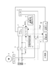
図1は、本発明の一実施例になるバッテリ充電制御装置の制御システム図で、本実施例では、このバッテリ充電制御装置を、電気自動車やハイブリッド車両など電動車両の走行に用いるメインバッテリ1を充電するためのものとする。
またメインバッテリ1は、複数個の電池シェルを積層してユニット化した電池モジュールを多数個、1セットにして一体化した、走行用モータの駆動に供し得る大容量のバッテリとする。
Hereinafter, embodiments of the present invention will be described in detail based on the illustrated examples.
<Configuration of Example>
FIG. 1 is a control system diagram of a battery charge control device according to an embodiment of the present invention. In this embodiment, a main battery 1 used for running an electric vehicle such as an electric vehicle or a hybrid vehicle is used as the battery charge control device. It shall be for charging.
The main battery 1 is a large-capacity battery that can be used to drive a motor for driving, in which a plurality of battery modules each formed by stacking a plurality of battery shells are integrated into one set.
図1において、2は、バッテリ1の温度調節を行うためのヒーターで、本発明における電力負荷に相当し、
このヒーター2は、上記の電池モジュールに対し、電池シェルの積層方向に沿うよう配置して、電池モジュールの直近に設け、バッテリ1を加温し得るものとする。
In FIG. 1, 2 is a heater for adjusting the temperature of the battery 1, which corresponds to the power load in the present invention,
The
図1において、3は、電動車両の走行駆動に用いる電動モータで、この電動モータ3は、インバータ4を介してバッテリ1に電気接続する。
そして、インバータ4およびバッテリ1間の電路中にメインリレースイッチ5を挿置し、このメインリレースイッチ5は、電動車両の図示せざるイグニッションスイッチに連動して、同じく図示せざる駆動コントローラを介し開閉され、イグニッションスイッチのON時に閉じ、イグニッションスイッチのOFF時に開くものとする。
In FIG. 1, reference numeral 3 denotes an electric motor used for driving the electric vehicle. The electric motor 3 is electrically connected to the battery 1 via the inverter 4.
Then, a main relay switch 5 is inserted in the electric path between the inverter 4 and the battery 1, and this main relay switch 5 is opened and closed via an unillustrated drive controller in conjunction with an unillustrated ignition switch of the electric vehicle. It is closed when the ignition switch is turned on and opened when the ignition switch is turned off.
イグニッションスイッチのONに連動してメインリレースイッチ5が閉じている間、バッテリ1からの直流電力は、インバータ4により直流→交流変換されると共に該インバータ4による制御下で電動モータ3に向け出力され、該モータ3の駆動により電動車両を走行させることができる。
イグニッションスイッチのOFFに連動してメインリレースイッチ5が開いている場合、バッテリ1からの直流電力は電動モータ3に向かい得ず、該モータ3の停止により電動車両を停車状態に保つことができる。
While the main relay switch 5 is closed in conjunction with the ON of the ignition switch, the DC power from the battery 1 is converted from DC to AC by the inverter 4 and output to the electric motor 3 under the control of the inverter 4. The electric vehicle can be driven by driving the motor 3.
When the main relay switch 5 is opened in conjunction with the ignition switch being turned off, the DC power from the battery 1 cannot go to the electric motor 3, and the electric vehicle can be kept stopped by stopping the motor 3.
インバータ4の直流側とメインリレースイッチ5との間には充電器7を接続して設け、この充電器7を、充電スタンドや自宅に在るバッテリ充電設備の外部電源に接続するとき、図示せざる充電コントローラによりメインリレースイッチ5が閉じられ、バッテリ1を外部電源により充電することができる。 A charger 7 is connected between the DC side of the inverter 4 and the main relay switch 5, and this charger 7 is not shown when connected to an external power source of a charging stand or a battery charging facility at home. The main relay switch 5 is closed by the charging controller, and the battery 1 can be charged by the external power source.
<バッテリ温度調節および充電制御>
上記の用に供されるバッテリ1の温度調節および充電制御を以下に説明する。
上記した通りバッテリ1の温度調節を行い得るよう、電池モジュールの直近において電池シェルの積層方向に沿うよう設けたヒーター2は、図1に示すごとくインバータ4の直流側とメインリレースイッチ5との間に電気接続し、この接続部とヒーター2との間の電路中にヒータースイッチ8を挿置する。
<Battery temperature control and charge control>
The temperature adjustment and charging control of the battery 1 provided for the above will be described below.
As described above, the
ヒータースイッチ8の開閉は、バッテリ1の温度調節および充電制御を司るコントローラ9により、リレー駆動回路11を介して制御する。
このコントローラ9は更に、メインリレースイッチ5がイグニッションスイッチのOFFに連動して開かれている間、および、メインリレースイッチ5が充電器7の外部電源への接続に連動して閉じられている間、当該メインリレースイッチ5をも、リレー駆動回路11を介して開閉制御するものとする。
The opening and closing of the
The controller 9 is further operated while the main relay switch 5 is opened in conjunction with the ignition switch being turned off and while the main relay switch 5 is closed in conjunction with the connection of the charger 7 to the external power source. The main relay switch 5 is also controlled to open and close via the
なおコントローラ9は、メインリレースイッチ5がイグニッションスイッチのOFFに連動して開かれている間、ヒータースイッチ8の「閉」に同期してメインリレースイッチ5をも閉じてヒーター2を附勢(ON)し、ヒータースイッチ8の「開」に同期してメインリレースイッチ5をも開いてヒーター2を滅勢(OFF)するものとする。
While the main relay switch 5 is opened in conjunction with the ignition switch OFF, the controller 9 closes the main relay switch 5 and energizes the
またコントローラ9は、メインリレースイッチ5が充電器7の外部電源への接続に連動して閉じられている間、ヒータースイッチ8が「閉」状態であることを条件に、メインリレースイッチ5を開閉制御して、本発明が狙いとする後述のバッテリ充電制御を行い、またヒータースイッチ8が「開」である場合は、メインリレースイッチ5を開いて、バッテリ充電を行わないものとする。
The controller 9 opens and closes the main relay switch 5 on the condition that the
コントローラ9には、ヒータースイッチ8およびメインリレースイッチ5の上記閉開を介したヒーター2のON,OFF制御(バッテリ温度調節のON,OFF)、およびバッテリ1の充電制御を行うために、
バッテリ1の蓄電状態SOCを検出するバッテリ蓄電状態検出センサ11からの信号と
バッテリ1の温度Tbatを検出するバッテリ温度センサ12からの信号と、
車両の使用者がバッテリ1の充電開始時刻および充電終了時刻間におけるバッテリ充電時刻を指令する時に操作する充電時刻指令器13からの信号とを入力する。
In the controller 9, in order to perform the ON / OFF control of the heater 2 (ON / OFF of the battery temperature adjustment) and the charging control of the battery 1 through the opening / closing of the
A signal from the battery storage
The vehicle user inputs a signal from the charging
なお充電時刻指令器13は、安価な深夜電力を用いたバッテリ1の満充電によりランニングコストを抑えたり、出発時刻に丁度バッテリ1が満充電になって走行距離が最長になるようにするなどのために、車両の使用者がバッテリ充電時刻を指令するためのものである。
The
コントローラ9は、これら入力情報を基に図示せざる制御プログラムを実行してバッテリ温度調節を行うと共に、図2に示す制御プログラムを実行して、バッテリ1の充電制御を以下の要領で行う。 Based on these input information, the controller 9 executes a control program (not shown) to adjust the battery temperature, and also executes the control program shown in FIG. 2 to control the charging of the battery 1 in the following manner.
先ず、イグニッションスイッチOFF(メインリレースイッチ5の「開」)により、電動モータ3(インバータ4)から切り離されて不使用状態となっているバッテリ1の温度調節を概略説明する。
不使用状態のバッテリ1は、特に厳寒地において電解液の凍結により入出力可能電力が0となり、走行不能になることから、適宜ヒーター2を作動させてバッテリ1を加温し、温度調節する必要がある。
このため、イグニッションスイッチOFF中は、バッテリ温度Tbatが図3に例示する加温開始温度Tbat_start(例えば-17℃程未満か、また同じく図3に例示する加温終了温度Tbat_stop(例えば-10℃)以上か否かをチェックする。
First, the temperature adjustment of the battery 1 that is disconnected from the electric motor 3 (inverter 4) and is not in use by turning off the ignition switch ("opening" the main relay switch 5) will be schematically described.
Battery 1 that is not in use has zero input / output power due to freezing of the electrolyte, especially in extremely cold regions, and it becomes impossible to run. Therefore, it is necessary to operate
Therefore, when the ignition switch is OFF, the battery temperature Tbat is the heating start temperature Tbat_start illustrated in FIG. 3 (for example, less than about −17 ° C., or the heating end temperature Tbat_stop illustrated in FIG. 3 is also illustrated, for example −10 ° C.). Check if this is the case.
バッテリ温度Tbatが加温開始温度Tbat_start未満(Tbat<Tbat_start)に低下する図3の瞬時t1以前においては、差し当たってバッテリ電解液の凍結が心配ないから、コントローラ9はヒータースイッチ8およびメインリレースイッチ5を開くことにより、ヒーター2をOFFにしてバッテリ1の加温を行わない。
Before the instant t1 in FIG. 3 when the battery temperature Tbat falls below the warming start temperature Tbat_start (Tbat <Tbat_start), the controller 9 has a
バッテリ温度Tbatが加温開始温度Tbat_start未満(Tbat<Tbat_start)となる図3のt1に、コントローラ9はヒータースイッチ8およびメインリレースイッチ5を閉じることにより、ヒーター2をONにしてバッテリ1の加温を行う。
At t1 in FIG. 3 where the battery temperature Tbat is less than the heating start temperature Tbat_start (Tbat <Tbat_start), the controller 9 closes the
その後はコントローラ9が、上記時間隔の経過ごとに、バッテリ温度Tbatが加温終了温度Tbat_stop以上になったか否かをチェックし、図3の瞬時t1以降におけるごとくTbat≧Tbat_stopにならない間、コントローラ9は引き続きヒータースイッチ8およびメインリレースイッチ5の「閉」により、ヒーター2をONにしてバッテリ1の加温を継続する。
Thereafter, the controller 9 checks whether or not the battery temperature Tbat has become equal to or higher than the heating end temperature Tbat_stop every time the above-described time interval elapses. Continues to heat the battery 1 by turning on the
そしてTbat≧Tbat_stopになるとき、コントローラ9はヒータースイッチ8およびメインリレースイッチ5の「開」により、ヒーター2をOFFにしてバッテリ1の加温を終了する。
When Tbat ≧ Tbat_stop, the controller 9 turns off the
以上のサイクルの繰り返しにより、バッテリ1はTbat<Tbat_stopのままにされることがなく、電解液が凍結して走行不能になるのを防止することができる。
また、Tbat≧Tbat_stopになるとき、ヒーター2をOFFにしてバッテリ1の加温を終了するため、不要なヒーター2のONで電力が無駄に消費されるのを防止することができる。
By repeating the above cycle, the battery 1 is not left as Tbat <Tbat_stop, and it is possible to prevent the electrolytic solution from freezing and being unable to run.
Further, when Tbat ≧ Tbat_stop, the
次に、コントローラ9が実行するバッテリ1の充電制御を、図2に基づき詳述する。
図2の制御プログラムは、図3の瞬時t0におけるごとく充電器7を、充電スタンドや自宅に在るバッテリ充電設備の外部電源に接続したことで、メインリレースイッチ5が閉じられ、充電可能状態になった時から実行される。
Next, the charging control of the battery 1 executed by the controller 9 will be described in detail based on FIG.
The control program in FIG. 2 connects the charger 7 to the external power source of the charging station or the battery charging facility at home as shown in FIG. 3 at the instant t0, so that the main relay switch 5 is closed and the charging is possible. It will be executed from the time.
ステップS11においては、充電時刻指令器13によって指定された充電開始時刻および充電終了時刻間におけるタイマ充電予約時刻中か否かをチェックする。
図3では、指定された充電開始時刻を瞬時t1の後のt3とし、また指定された充電終了時刻を瞬時t4として示した。
In step S11, it is checked whether the timer charge reservation time is between the charge start time and the charge end time specified by the charge
In FIG. 3, the designated charging start time is shown as t3 after the instant t1, and the designated charging end time is shown as the instant t4.
ステップS11において今がタイマ充電予約時刻中(t3〜t4)でないと判定する場合、ステップS12において、ヒータースイッチ8がON中か否かにより、バッテリ1が加温中か否かをチェックする。
なお、図3の瞬時t0以降におけるように充電器接続状態では、充電器7からの電力が存在しているため、ヒータースイッチ8がONであれば、メインリレースイッチ5のON,OFFに関係なくヒーター2を作動させることができ、従ってステップS12では上記の通り、ヒータースイッチ8がON中か否かのみにより、バッテリ1が加温中か否かをチェックすることができる。
If it is determined in step S11 that the current time is not during the timer charging reservation time (t3 to t4), it is checked in step S12 whether or not the battery 1 is being heated depending on whether or not the
In addition, in the charger connected state as in the time t0 and after in FIG. 3, since the power from the charger 7 exists, if the
図3の加温開始瞬時t1よりも前のようにバッテリ1が加温中でなければ、ステップS13において、メインリレースイッチ5の「OFF」によりバッテリ1の充電を、図4の加温開始瞬時t1以前におけるバッテリ充電電力Pchg=0から明らかなように、禁止して行わないようにする。 If the battery 1 is not warming before the warming start instant t1 in FIG. 3, in step S13, the main relay switch 5 is turned off to charge the battery 1, and the warming start instant in FIG. As is clear from the battery charge power Pchg = 0 before t1, it is prohibited and is not performed.
ステップS12でヒーター2のONによるバッテリ1の加温中と判定する場合、ステップS14において、当該加温の開始時(図3ではt1)に取得すべきバッテリ保持容量SOCholdを既に取得済みであるか否かをチェックする。
未だバッテリ保持容量SOCholdを取得済みでなければ、ステップS15において加温開始時(図3ではt1)のバッテリ蓄電状態SOC(t1)をバッテリ保持容量SOCholdに設定した後、制御をステップS16に進め、
既にステップS15の実行によりバッテリ保持容量SOCholdを取得済みであれば、このステップS15をスキップして、制御をステップS16に進める。
If it is determined in step S12 that the battery 1 is being heated by turning on the
If the battery holding capacity SOChold has not yet been acquired, the battery storage state SOC (t1) at the start of heating (t1 in FIG. 3) is set to the battery holding capacity SOChold in step S15, and then control proceeds to step S16.
If the battery holding capacity SOChold has already been acquired by executing step S15, step S15 is skipped and control proceeds to step S16.
ステップS16は、本発明における蓄電状態保持用充電電力制御手段に相当するもので、このステップS16においては、バッテリ蓄電状態SOCがバッテリ保持容量SOCholdに保たれるようメインリレースイッチ5のON,OFFによりバッテリ1への充電電力Pchgを制御する。
この制御は、SOC<SOCholdであれば、メインリレースイッチ5のONにより充電器7からバッテリ1へ充電電力を供給し、またSOC=SOCholdになったら、メインリレースイッチ5のOFFにより充電器7からバッテリ1へ充電電力が供給されないようにすることで、実現可能である。
Step S16 corresponds to the storage state holding charge power control means in the present invention. In this step S16, the main relay switch 5 is turned on and off so that the battery storage state SOC is maintained at the battery holding capacity SOChold. The charging power Pchg to the battery 1 is controlled.
In this control, if SOC <SOChold, the main relay switch 5 is turned on to supply charging power from the charger 7 to the battery 1, and when SOC = SOChold, the main relay switch 5 is turned off to turn off the charger 7. This can be realized by preventing charging power from being supplied to the battery 1.
かようにバッテリ蓄電状態SOCがバッテリ保持容量SOCholdに保たれるようバッテリ1への充電電力Pchgを制御する場合、以下のような効果が得られる。 Thus, when the charging power Pchg to the battery 1 is controlled so that the battery storage state SOC is maintained at the battery holding capacity SOChold, the following effects are obtained.
図4は、図3の加温開始時t1と、指定された充電開始時刻t3との間における時間軸を、図3よりも拡大して示すもので、瞬時t1の直後にヒーター消費電力Pheatが急増し、その分だけバッテリ蓄電状態SOCが、瞬時t1の直後におけるバッテリ電圧Vbatの実線で示す低下傾向から明らかなごとく一時的に悪化する。
かかるバッテリ蓄電状態SOCの悪化を放置しておくと、図3のタイマ予約充電時刻t3〜t4中にバッテリ蓄電状態SOCを狙い通り満充電状態にし得なくなり、安価な深夜電力を用いた充電割合が低下してランニングコストが高くなったり、瞬時t4の充電終了後における走行開始時にバッテリ1が満充電状態でなくて、走行距離が短くなるという問題を生ずる。
FIG. 4 shows the time axis between the heating start time t1 in FIG. 3 and the specified charging start time t3 in an enlarged manner as compared with FIG. 3, and the heater power consumption Pheat is immediately after the instant t1. The battery storage state SOC is suddenly increased by that amount, and temporarily deteriorates as apparent from the downward trend indicated by the solid line of the battery voltage Vbat immediately after the instant t1.
If the deterioration of the battery charge state SOC is left unattended, the battery charge state SOC cannot be fully charged as intended during the timer reserved charge times t3 to t4 in FIG. There arises a problem that the running cost increases due to a decrease, or the running distance is shortened because the battery 1 is not fully charged at the start of running after the end of charging at the instant t4.
ところで本実施例においてはステップS16で、バッテリ蓄電状態SOCがバッテリ保持容量SOCholdに保たれるようバッテリ1への充電電力Pchgを、図4の加温開始時t1の直後に図4に示すごとくに増大させるため、瞬時t1の直後においてもバッテリ電圧Vbatを波線で示すごとく、バッテリ保持容量SOChold相当のレベルに保つことができる。
このため、図3のタイマ予約充電時刻t3〜t4以外にバッテリ蓄電状態SOCを瞬時t1のレベルよりも増大させるバッテリ充電が行われることがなくて、図3のタイマ予約充電時刻t3〜t4中にバッテリ蓄電状態SOCを狙い通り満充電状態にすることができ、安価な深夜電力を用いた充電割合を最大限に高めてランニングコストを抑制することができ、また瞬時t4の充電終了後における走行開始時に確実にバッテリ1を満充電状態にすることができ、走行距離を最大限が延長することができる。
By the way, in this embodiment, in step S16, the charging power Pchg to the battery 1 is shown in FIG. 4 immediately after the heating start t1 in FIG. 4 so that the battery storage state SOC is maintained at the battery holding capacity SOChold. In order to increase, the battery voltage Vbat can be maintained at a level equivalent to the battery holding capacity SOChold as indicated by the wavy line even immediately after the instant t1.
For this reason, there is no battery charging that increases the battery storage state SOC beyond the instantaneous t1 level other than the timer reserved charging times t3 to t4 in FIG. 3, and during the timer reserved charging times t3 to t4 in FIG. The battery state of charge SOC can be fully charged as intended, and the running rate can be suppressed by maximizing the charging rate using inexpensive late-night power, and running after the instant t4 charging ends Sometimes the battery 1 can be fully charged and the mileage can be extended to the maximum.
図2のステップS11で今が、充電開始時刻t3(図3参照)および充電終了時刻t4(図3参照)間におけるタイマ充電予約時刻中と判定する場合、制御をステップS17に進める。
このステップS17においては、バッテリ蓄電状態SOCが満充電状態SOCfullとなるようメインリレースイッチ5のON,OFFによりバッテリ1への充電電力Pchgを制御する。
この制御は、SOC<SOCfullであれば、メインリレースイッチ5のONにより充電器7からバッテリ1へ充電電力を供給し、またSOC=SOCfullになったら、メインリレースイッチ5のOFFにより充電器7からバッテリ1へ充電電力が供給されないようにすることで、実現可能である。
If it is determined in step S11 of FIG. 2 that the timer charging reservation time is between the charging start time t3 (see FIG. 3) and the charging end time t4 (see FIG. 3), the control proceeds to step S17.
In step S17, the charging power Pchg to the battery 1 is controlled by turning on and off the main relay switch 5 so that the battery storage state SOC becomes the full charge state SOCfull.
In this control, if SOC <SOCfull, the main relay switch 5 is turned on to supply charging power from the charger 7 to the battery 1, and when SOC = SOCfull, the main relay switch 5 is turned off to turn off the charger 7. This can be realized by preventing charging power from being supplied to the battery 1.
かようにタイマ充電予約時刻中t3〜t4にバッテリ蓄電状態SOCが満充電状態SOCfullとなるようバッテリ1への充電を行う場合、タイマ充電予約時刻の指定意図を確実に達成することができ、
当該満充電のために消費される電力を全て、安価な深夜電力で賄うこととなって、ランニングコストを抑制することができる。
Thus, when charging the battery 1 so that the battery charge state SOC becomes the full charge state SOCfull during the timer charge reservation time t3 to t4, the designation intention of the timer charge reservation time can be reliably achieved,
Since all the power consumed for the full charge is covered with inexpensive late-night power, the running cost can be suppressed.
<実施例の効果>
上記した本実施例のバッテリ充電制御装置によれば、図3,4に示すように、
瞬時t1以降のヒーター2(電力負荷)の作動によるバッテリ1の加温中、今がタイマ充電予約時刻(t3〜t4)であるか否かに応じ、
今がタイマ充電予約時刻(t3〜t4)でなければ、バッテリ蓄電状態SOCが、加温開始時t1のバッテリ蓄電状態SOC(t1)であるバッテリ保持容量SOCholdに保たれるようバッテリ1への充電電力Pchgを制御するため、
図4に示すごとく加温開始時t1の直後にヒーター消費電力Pheatが急増し、その分だけバッテリ蓄電状態SOCが、瞬時t1の直後におけるバッテリ電圧Vbatの実線で示す低下傾向から明らかなごとく一時的に悪化する傾向にあっても、
瞬時t1の直後におけるバッテリ電圧Vbatを波線で示すごとく、バッテリ保持容量SOChold相当のレベルに保つことができる。
<Effect of Example>
According to the battery charge control device of the present embodiment described above, as shown in FIGS.
During heating of battery 1 by the operation of heater 2 (electric power load) after instant t1, depending on whether or not now is the timer charging reservation time (t3 to t4)
If it is not the timer charge reservation time (t3 to t4), the battery 1 is charged so that the battery charge state SOC is maintained at the battery hold capacity SOChold that is the battery charge state SOC (t1) at the start of heating t1. To control the power Pchg,
As shown in FIG. 4, the heater power consumption Pheat suddenly increases immediately after the start of heating t1, and the battery storage state SOC is temporarily increased by an amount corresponding to the downward trend indicated by the solid line of the battery voltage Vbat immediately after the instant t1. Even if you tend to get worse,
The battery voltage Vbat immediately after the instant t1 can be maintained at a level equivalent to the battery holding capacity SOChold as indicated by a broken line.
従って、図3のタイマ予約充電時刻t3〜t4以外にバッテリ蓄電状態SOCを瞬時t1のレベルよりも増大させるバッテリ充電が行われることがなくて、その後における図3のタイマ予約充電時刻t3〜t4中にバッテリ蓄電状態SOCを狙い通り満充電状態にすることができ、安価な深夜電力を用いた充電割合を最大限に高めてランニングコストを抑制することができ、
また瞬時t4の充電終了後における走行開始時に確実にバッテリ1を満充電状態にすることができ、走行距離を最大限が延長することができる。
Therefore, there is no battery charging that increases the battery storage state SOC beyond the instantaneous t1 level other than the timer reserved charging times t3 to t4 in FIG. 3, and thereafter during the timer reserved charging times t3 to t4 in FIG. The battery charge state SOC can be fully charged as intended, the running rate can be suppressed by maximizing the charging rate using cheap late-night power,
In addition, the battery 1 can be surely fully charged at the start of travel after the end of charging at the instant t4, and the travel distance can be extended to the maximum.
また、今がタイマ充電予約時刻(t3〜t4)である場合は、バッテリ蓄電状態SOCが満充電状態SOCfullにされるようバッテリ1への充電電力Pchgを制御するため、
当該満充電のために消費される電力を全て、安価な深夜電力で賄うこととなって、ランニングコストを抑制することができる。
In addition, when now is the timer charging reservation time (t3 to t4), in order to control the charging power Pchg to the battery 1 so that the battery charge state SOC is set to the full charge state SOCfull,
Since all the power consumed for the full charge is covered with inexpensive late-night power, the running cost can be suppressed.
1 メインバッテリ
2 ヒーター
3 電動モータ
4 インバータ
5 メインリレースイッチ
7 充電器
8 ヒータースイッチ
9 コントローラ
11 バッテリ蓄電状態センサ
12 バッテリ温度センサ
13 充電時刻指令器
1 Main battery
2 Heater
3 Electric motor
4 Inverter
5 Main relay switch
7 Charger
8 Heater switch
9 Controller
11 Battery charge state sensor
12 Battery temperature sensor
13 Charging time command unit
Claims (3)
前記電力負荷が作動されている間、前記指定した充電時刻中でない場合は、前記バッテリへの充電電力を、満充電よりも小さな所定のバッテリ蓄電状態に保持する蓄電状態保持用充電電力制御手段を設けたことを特徴とするバッテリ充電制御装置。 A battery charge control device comprising: a battery that can be charged by designating a charging time; and a power load that is connected to a charging power system of the battery and that is operated by power passing through the charging power system when a predetermined condition is satisfied. ,
When the power load is being operated, if the specified charging time is not being reached, charging power control means for holding the storage state holds the charging power to the battery in a predetermined battery storage state smaller than full charge. A battery charge control device provided.
前記小さな所定のバッテリ蓄電状態は、前記電力負荷が作動を開始した時のバッテリ蓄電状態にバッテリを保つのに必要な充電電力であることを特徴とするバッテリ充電制御装置。 In the battery charge control device according to claim 1,
The battery charge control apparatus according to claim 1, wherein the small predetermined battery charge state is charge power necessary to keep the battery in a battery charge state when the power load starts to operate.
前記電力負荷が、バッテリを所定温度未満になるときに加温して温度調節するヒーターであることを特徴とするバッテリ充電制御装置。 In the battery charge control device according to claim 1 or 2,
The battery charge control device, wherein the power load is a heater that heats and adjusts the temperature of the battery when the temperature falls below a predetermined temperature.
Priority Applications (6)
| Application Number | Priority Date | Filing Date | Title |
|---|---|---|---|
| JP2011054094A JP5736860B2 (en) | 2011-03-11 | 2011-03-11 | Battery charge control device |
| CN201280012912.XA CN103430423B (en) | 2011-03-11 | 2012-03-01 | Battery charging control device |
| KR1020137023910A KR101571943B1 (en) | 2011-03-11 | 2012-03-01 | Battery charging control device |
| PCT/JP2012/055209 WO2012124490A1 (en) | 2011-03-11 | 2012-03-01 | Battery charging control device |
| EP12757908.4A EP2685599B1 (en) | 2011-03-11 | 2012-03-01 | Battery charging control device |
| US14/003,951 US20130342015A1 (en) | 2011-03-11 | 2012-03-01 | Battery charging control device |
Applications Claiming Priority (1)
| Application Number | Priority Date | Filing Date | Title |
|---|---|---|---|
| JP2011054094A JP5736860B2 (en) | 2011-03-11 | 2011-03-11 | Battery charge control device |
Publications (2)
| Publication Number | Publication Date |
|---|---|
| JP2012191785A true JP2012191785A (en) | 2012-10-04 |
| JP5736860B2 JP5736860B2 (en) | 2015-06-17 |
Family
ID=46830565
Family Applications (1)
| Application Number | Title | Priority Date | Filing Date |
|---|---|---|---|
| JP2011054094A Active JP5736860B2 (en) | 2011-03-11 | 2011-03-11 | Battery charge control device |
Country Status (6)
| Country | Link |
|---|---|
| US (1) | US20130342015A1 (en) |
| EP (1) | EP2685599B1 (en) |
| JP (1) | JP5736860B2 (en) |
| KR (1) | KR101571943B1 (en) |
| CN (1) | CN103430423B (en) |
| WO (1) | WO2012124490A1 (en) |
Cited By (2)
| Publication number | Priority date | Publication date | Assignee | Title |
|---|---|---|---|---|
| JP2015043662A (en) * | 2013-08-26 | 2015-03-05 | トヨタ自動車株式会社 | Power storage system |
| JP2016208639A (en) * | 2015-04-21 | 2016-12-08 | トヨタ自動車株式会社 | vehicle |
Families Citing this family (13)
| Publication number | Priority date | Publication date | Assignee | Title |
|---|---|---|---|---|
| CN103419660B (en) * | 2012-05-22 | 2016-03-30 | 比亚迪股份有限公司 | The power system of electronlmobil, electronlmobil and heating of battery method |
| WO2014045776A1 (en) * | 2012-09-19 | 2014-03-27 | 日産自動車株式会社 | Vehicle control system, vehicle information supply device, and vehicle information supply method |
| JP6331697B2 (en) * | 2014-05-28 | 2018-05-30 | トヨタ自動車株式会社 | Power storage system |
| SE539037C2 (en) * | 2015-12-08 | 2017-03-28 | Scania Cv Ab | Method and control system for charging an accessory battery and a hybrid energy storage of a plug-in hybrid vehicle |
| US10108245B2 (en) | 2016-04-11 | 2018-10-23 | Microsoft Technology Licensing, Llc | Interaction based charging control |
| JP6520848B2 (en) * | 2016-07-04 | 2019-05-29 | トヨタ自動車株式会社 | Battery charging system for electric vehicles |
| JP6493344B2 (en) * | 2016-09-12 | 2019-04-03 | トヨタ自動車株式会社 | Automobile |
| KR20180070892A (en) | 2016-12-19 | 2018-06-27 | 현대자동차주식회사 | Electric vehicle, system having the same and battery charging method of vehicle |
| WO2018161010A1 (en) | 2017-03-03 | 2018-09-07 | Gentherm Incorporated | Dual voltage battery system for a vehicle |
| US10664365B2 (en) | 2017-08-21 | 2020-05-26 | Google Llc | System and method for monitoring and controlling a back-up power supply using temperature controlled batteries |
| KR102212445B1 (en) * | 2019-02-01 | 2021-02-04 | 주식회사 현대케피코 | Control apparatus and method for IG relay control circuit for pre-charging of vehicle battery |
| TWI726373B (en) * | 2019-08-01 | 2021-05-01 | 拓連科技股份有限公司 | Charging management server and method for charging management |
| CN112339601A (en) * | 2020-11-11 | 2021-02-09 | 上海电享信息科技有限公司 | Intelligent charging method and system for electric automobile |
Citations (4)
| Publication number | Priority date | Publication date | Assignee | Title |
|---|---|---|---|---|
| JPH08214411A (en) * | 1995-02-06 | 1996-08-20 | Honda Motor Co Ltd | Battery charge controller for electric vehicle |
| JP2008238912A (en) * | 2007-03-27 | 2008-10-09 | Equos Research Co Ltd | Electric driving control device and electric driving control method |
| US20090114463A1 (en) * | 2007-06-12 | 2009-05-07 | Devault Robert C | Self-learning control system for plug-in hybrid vehicles |
| JP2010285110A (en) * | 2009-06-12 | 2010-12-24 | Toyota Motor Corp | Vehicle and method for controlling the same |
Family Cites Families (14)
| Publication number | Priority date | Publication date | Assignee | Title |
|---|---|---|---|---|
| US5710507A (en) * | 1996-04-26 | 1998-01-20 | Lucent Technologies Inc. | Temperature-controlled battery reserve system and method of operation thereof |
| JP2000040536A (en) | 1998-07-23 | 2000-02-08 | Toyota Motor Corp | Battery warming up device |
| JP2002233074A (en) | 2001-02-05 | 2002-08-16 | Nec Corp | Battery charge and discharge system |
| JP4281725B2 (en) * | 2005-09-01 | 2009-06-17 | トヨタ自動車株式会社 | Hybrid car |
| US9457791B2 (en) * | 2009-01-06 | 2016-10-04 | GM Global Technology Operations LLC | Charging cable with controller |
| US8118237B2 (en) * | 2009-02-16 | 2012-02-21 | General Electric Company | System and method for vehicle temperature control |
| US20100292855A1 (en) * | 2009-05-14 | 2010-11-18 | Michael Kintner-Meyer | Battery Charging Control Methods, Electrical Vehicle Charging Methods, Battery Charging Control Apparatus, and Electrical Vehicles |
| US8890473B2 (en) * | 2009-07-28 | 2014-11-18 | Bosch Automotive Service Solutions Llc | Sequential charging of multiple electric vehicles |
| US9431688B2 (en) * | 2010-05-21 | 2016-08-30 | GM Global Technology Operations LLC | Method for heating a high voltage vehicle battery |
| KR101185735B1 (en) * | 2010-07-16 | 2012-09-26 | 엘에스산전 주식회사 | Battery disconnect unit for electric vehicle |
| JP5699702B2 (en) * | 2011-03-11 | 2015-04-15 | 日産自動車株式会社 | Vehicle charging control device |
| JP5668542B2 (en) * | 2011-03-11 | 2015-02-12 | 日産自動車株式会社 | Vehicle charging control device |
| JP5668541B2 (en) * | 2011-03-11 | 2015-02-12 | 日産自動車株式会社 | Vehicle charging control device |
| JP5732930B2 (en) * | 2011-03-11 | 2015-06-10 | 日産自動車株式会社 | Battery charge control device |
-
2011
- 2011-03-11 JP JP2011054094A patent/JP5736860B2/en active Active
-
2012
- 2012-03-01 KR KR1020137023910A patent/KR101571943B1/en active IP Right Grant
- 2012-03-01 EP EP12757908.4A patent/EP2685599B1/en active Active
- 2012-03-01 WO PCT/JP2012/055209 patent/WO2012124490A1/en active Application Filing
- 2012-03-01 US US14/003,951 patent/US20130342015A1/en not_active Abandoned
- 2012-03-01 CN CN201280012912.XA patent/CN103430423B/en active Active
Patent Citations (4)
| Publication number | Priority date | Publication date | Assignee | Title |
|---|---|---|---|---|
| JPH08214411A (en) * | 1995-02-06 | 1996-08-20 | Honda Motor Co Ltd | Battery charge controller for electric vehicle |
| JP2008238912A (en) * | 2007-03-27 | 2008-10-09 | Equos Research Co Ltd | Electric driving control device and electric driving control method |
| US20090114463A1 (en) * | 2007-06-12 | 2009-05-07 | Devault Robert C | Self-learning control system for plug-in hybrid vehicles |
| JP2010285110A (en) * | 2009-06-12 | 2010-12-24 | Toyota Motor Corp | Vehicle and method for controlling the same |
Cited By (2)
| Publication number | Priority date | Publication date | Assignee | Title |
|---|---|---|---|---|
| JP2015043662A (en) * | 2013-08-26 | 2015-03-05 | トヨタ自動車株式会社 | Power storage system |
| JP2016208639A (en) * | 2015-04-21 | 2016-12-08 | トヨタ自動車株式会社 | vehicle |
Also Published As
| Publication number | Publication date |
|---|---|
| CN103430423A (en) | 2013-12-04 |
| JP5736860B2 (en) | 2015-06-17 |
| US20130342015A1 (en) | 2013-12-26 |
| EP2685599A4 (en) | 2014-08-27 |
| EP2685599A1 (en) | 2014-01-15 |
| EP2685599B1 (en) | 2017-09-06 |
| KR101571943B1 (en) | 2015-11-25 |
| KR20130135911A (en) | 2013-12-11 |
| CN103430423B (en) | 2016-05-25 |
| WO2012124490A1 (en) | 2012-09-20 |
Similar Documents
| Publication | Publication Date | Title |
|---|---|---|
| JP5736860B2 (en) | Battery charge control device | |
| JP5732930B2 (en) | Battery charge control device | |
| KR101609034B1 (en) | Battery temperature control device | |
| CN108028442B (en) | Heating control device for storage battery | |
| WO2012124485A1 (en) | Battery temperature control device | |
| WO2017056162A1 (en) | Power consumption control device | |
| WO2012124477A1 (en) | Battery temperature control device | |
| WO2013129217A1 (en) | Electric vehicle | |
| JP2016152067A (en) | Power storage system | |
| JP2014075297A (en) | Power storage system | |
| JP6332131B2 (en) | Electric vehicle | |
| JP2016111721A (en) | Charge control device of vehicle | |
| JP2012109045A (en) | Battery system, vehicle with battery system, and method for heating secondary battery | |
| JP6402687B2 (en) | Vehicle battery system | |
| JP7439775B2 (en) | Electric vehicle power system | |
| CN113997829B (en) | Control method for guaranteeing stable and non-stop charging and heating of electric automobile battery | |
| JP2022149837A (en) | Heating system of vehicle |
Legal Events
| Date | Code | Title | Description |
|---|---|---|---|
| A621 | Written request for application examination |
Free format text: JAPANESE INTERMEDIATE CODE: A621 Effective date: 20140129 |
|
| A131 | Notification of reasons for refusal |
Free format text: JAPANESE INTERMEDIATE CODE: A131 Effective date: 20141209 |
|
| A521 | Request for written amendment filed |
Free format text: JAPANESE INTERMEDIATE CODE: A523 Effective date: 20150203 |
|
| TRDD | Decision of grant or rejection written | ||
| A01 | Written decision to grant a patent or to grant a registration (utility model) |
Free format text: JAPANESE INTERMEDIATE CODE: A01 Effective date: 20150324 |
|
| A61 | First payment of annual fees (during grant procedure) |
Free format text: JAPANESE INTERMEDIATE CODE: A61 Effective date: 20150406 |
|
| R151 | Written notification of patent or utility model registration |
Ref document number: 5736860 Country of ref document: JP Free format text: JAPANESE INTERMEDIATE CODE: R151 |