JP2012191781A - Vehicle charge control device - Google Patents
Vehicle charge control device Download PDFInfo
- Publication number
- JP2012191781A JP2012191781A JP2011054087A JP2011054087A JP2012191781A JP 2012191781 A JP2012191781 A JP 2012191781A JP 2011054087 A JP2011054087 A JP 2011054087A JP 2011054087 A JP2011054087 A JP 2011054087A JP 2012191781 A JP2012191781 A JP 2012191781A
- Authority
- JP
- Japan
- Prior art keywords
- charging
- battery
- time
- timer
- temperature
- Prior art date
- Legal status (The legal status is an assumption and is not a legal conclusion. Google has not performed a legal analysis and makes no representation as to the accuracy of the status listed.)
- Granted
Links
Images


Classifications
-
- B—PERFORMING OPERATIONS; TRANSPORTING
- B60—VEHICLES IN GENERAL
- B60L—PROPULSION OF ELECTRICALLY-PROPELLED VEHICLES; SUPPLYING ELECTRIC POWER FOR AUXILIARY EQUIPMENT OF ELECTRICALLY-PROPELLED VEHICLES; ELECTRODYNAMIC BRAKE SYSTEMS FOR VEHICLES IN GENERAL; MAGNETIC SUSPENSION OR LEVITATION FOR VEHICLES; MONITORING OPERATING VARIABLES OF ELECTRICALLY-PROPELLED VEHICLES; ELECTRIC SAFETY DEVICES FOR ELECTRICALLY-PROPELLED VEHICLES
- B60L1/00—Supplying electric power to auxiliary equipment of vehicles
- B60L1/02—Supplying electric power to auxiliary equipment of vehicles to electric heating circuits
-
- B—PERFORMING OPERATIONS; TRANSPORTING
- B60—VEHICLES IN GENERAL
- B60L—PROPULSION OF ELECTRICALLY-PROPELLED VEHICLES; SUPPLYING ELECTRIC POWER FOR AUXILIARY EQUIPMENT OF ELECTRICALLY-PROPELLED VEHICLES; ELECTRODYNAMIC BRAKE SYSTEMS FOR VEHICLES IN GENERAL; MAGNETIC SUSPENSION OR LEVITATION FOR VEHICLES; MONITORING OPERATING VARIABLES OF ELECTRICALLY-PROPELLED VEHICLES; ELECTRIC SAFETY DEVICES FOR ELECTRICALLY-PROPELLED VEHICLES
- B60L50/00—Electric propulsion with power supplied within the vehicle
- B60L50/50—Electric propulsion with power supplied within the vehicle using propulsion power supplied by batteries or fuel cells
- B60L50/51—Electric propulsion with power supplied within the vehicle using propulsion power supplied by batteries or fuel cells characterised by AC-motors
-
- B—PERFORMING OPERATIONS; TRANSPORTING
- B60—VEHICLES IN GENERAL
- B60L—PROPULSION OF ELECTRICALLY-PROPELLED VEHICLES; SUPPLYING ELECTRIC POWER FOR AUXILIARY EQUIPMENT OF ELECTRICALLY-PROPELLED VEHICLES; ELECTRODYNAMIC BRAKE SYSTEMS FOR VEHICLES IN GENERAL; MAGNETIC SUSPENSION OR LEVITATION FOR VEHICLES; MONITORING OPERATING VARIABLES OF ELECTRICALLY-PROPELLED VEHICLES; ELECTRIC SAFETY DEVICES FOR ELECTRICALLY-PROPELLED VEHICLES
- B60L53/00—Methods of charging batteries, specially adapted for electric vehicles; Charging stations or on-board charging equipment therefor; Exchange of energy storage elements in electric vehicles
- B60L53/10—Methods of charging batteries, specially adapted for electric vehicles; Charging stations or on-board charging equipment therefor; Exchange of energy storage elements in electric vehicles characterised by the energy transfer between the charging station and the vehicle
- B60L53/14—Conductive energy transfer
- B60L53/18—Cables specially adapted for charging electric vehicles
-
- B—PERFORMING OPERATIONS; TRANSPORTING
- B60—VEHICLES IN GENERAL
- B60L—PROPULSION OF ELECTRICALLY-PROPELLED VEHICLES; SUPPLYING ELECTRIC POWER FOR AUXILIARY EQUIPMENT OF ELECTRICALLY-PROPELLED VEHICLES; ELECTRODYNAMIC BRAKE SYSTEMS FOR VEHICLES IN GENERAL; MAGNETIC SUSPENSION OR LEVITATION FOR VEHICLES; MONITORING OPERATING VARIABLES OF ELECTRICALLY-PROPELLED VEHICLES; ELECTRIC SAFETY DEVICES FOR ELECTRICALLY-PROPELLED VEHICLES
- B60L53/00—Methods of charging batteries, specially adapted for electric vehicles; Charging stations or on-board charging equipment therefor; Exchange of energy storage elements in electric vehicles
- B60L53/60—Monitoring or controlling charging stations
- B60L53/62—Monitoring or controlling charging stations in response to charging parameters, e.g. current, voltage or electrical charge
-
- B—PERFORMING OPERATIONS; TRANSPORTING
- B60—VEHICLES IN GENERAL
- B60L—PROPULSION OF ELECTRICALLY-PROPELLED VEHICLES; SUPPLYING ELECTRIC POWER FOR AUXILIARY EQUIPMENT OF ELECTRICALLY-PROPELLED VEHICLES; ELECTRODYNAMIC BRAKE SYSTEMS FOR VEHICLES IN GENERAL; MAGNETIC SUSPENSION OR LEVITATION FOR VEHICLES; MONITORING OPERATING VARIABLES OF ELECTRICALLY-PROPELLED VEHICLES; ELECTRIC SAFETY DEVICES FOR ELECTRICALLY-PROPELLED VEHICLES
- B60L58/00—Methods or circuit arrangements for monitoring or controlling batteries or fuel cells, specially adapted for electric vehicles
- B60L58/10—Methods or circuit arrangements for monitoring or controlling batteries or fuel cells, specially adapted for electric vehicles for monitoring or controlling batteries
- B60L58/12—Methods or circuit arrangements for monitoring or controlling batteries or fuel cells, specially adapted for electric vehicles for monitoring or controlling batteries responding to state of charge [SoC]
-
- B—PERFORMING OPERATIONS; TRANSPORTING
- B60—VEHICLES IN GENERAL
- B60L—PROPULSION OF ELECTRICALLY-PROPELLED VEHICLES; SUPPLYING ELECTRIC POWER FOR AUXILIARY EQUIPMENT OF ELECTRICALLY-PROPELLED VEHICLES; ELECTRODYNAMIC BRAKE SYSTEMS FOR VEHICLES IN GENERAL; MAGNETIC SUSPENSION OR LEVITATION FOR VEHICLES; MONITORING OPERATING VARIABLES OF ELECTRICALLY-PROPELLED VEHICLES; ELECTRIC SAFETY DEVICES FOR ELECTRICALLY-PROPELLED VEHICLES
- B60L58/00—Methods or circuit arrangements for monitoring or controlling batteries or fuel cells, specially adapted for electric vehicles
- B60L58/10—Methods or circuit arrangements for monitoring or controlling batteries or fuel cells, specially adapted for electric vehicles for monitoring or controlling batteries
- B60L58/24—Methods or circuit arrangements for monitoring or controlling batteries or fuel cells, specially adapted for electric vehicles for monitoring or controlling batteries for controlling the temperature of batteries
- B60L58/27—Methods or circuit arrangements for monitoring or controlling batteries or fuel cells, specially adapted for electric vehicles for monitoring or controlling batteries for controlling the temperature of batteries by heating
-
- H—ELECTRICITY
- H01—ELECTRIC ELEMENTS
- H01M—PROCESSES OR MEANS, e.g. BATTERIES, FOR THE DIRECT CONVERSION OF CHEMICAL ENERGY INTO ELECTRICAL ENERGY
- H01M10/00—Secondary cells; Manufacture thereof
- H01M10/42—Methods or arrangements for servicing or maintenance of secondary cells or secondary half-cells
- H01M10/44—Methods for charging or discharging
- H01M10/443—Methods for charging or discharging in response to temperature
-
- H—ELECTRICITY
- H01—ELECTRIC ELEMENTS
- H01M—PROCESSES OR MEANS, e.g. BATTERIES, FOR THE DIRECT CONVERSION OF CHEMICAL ENERGY INTO ELECTRICAL ENERGY
- H01M10/00—Secondary cells; Manufacture thereof
- H01M10/42—Methods or arrangements for servicing or maintenance of secondary cells or secondary half-cells
- H01M10/48—Accumulators combined with arrangements for measuring, testing or indicating the condition of cells, e.g. the level or density of the electrolyte
- H01M10/486—Accumulators combined with arrangements for measuring, testing or indicating the condition of cells, e.g. the level or density of the electrolyte for measuring temperature
-
- H—ELECTRICITY
- H01—ELECTRIC ELEMENTS
- H01M—PROCESSES OR MEANS, e.g. BATTERIES, FOR THE DIRECT CONVERSION OF CHEMICAL ENERGY INTO ELECTRICAL ENERGY
- H01M10/00—Secondary cells; Manufacture thereof
- H01M10/60—Heating or cooling; Temperature control
- H01M10/61—Types of temperature control
- H01M10/615—Heating or keeping warm
-
- H—ELECTRICITY
- H01—ELECTRIC ELEMENTS
- H01M—PROCESSES OR MEANS, e.g. BATTERIES, FOR THE DIRECT CONVERSION OF CHEMICAL ENERGY INTO ELECTRICAL ENERGY
- H01M10/00—Secondary cells; Manufacture thereof
- H01M10/60—Heating or cooling; Temperature control
- H01M10/62—Heating or cooling; Temperature control specially adapted for specific applications
- H01M10/625—Vehicles
-
- H—ELECTRICITY
- H01—ELECTRIC ELEMENTS
- H01M—PROCESSES OR MEANS, e.g. BATTERIES, FOR THE DIRECT CONVERSION OF CHEMICAL ENERGY INTO ELECTRICAL ENERGY
- H01M10/00—Secondary cells; Manufacture thereof
- H01M10/60—Heating or cooling; Temperature control
- H01M10/63—Control systems
-
- H—ELECTRICITY
- H01—ELECTRIC ELEMENTS
- H01M—PROCESSES OR MEANS, e.g. BATTERIES, FOR THE DIRECT CONVERSION OF CHEMICAL ENERGY INTO ELECTRICAL ENERGY
- H01M10/00—Secondary cells; Manufacture thereof
- H01M10/60—Heating or cooling; Temperature control
- H01M10/66—Heat-exchange relationships between the cells and other systems, e.g. central heating systems or fuel cells
-
- H—ELECTRICITY
- H02—GENERATION; CONVERSION OR DISTRIBUTION OF ELECTRIC POWER
- H02J—CIRCUIT ARRANGEMENTS OR SYSTEMS FOR SUPPLYING OR DISTRIBUTING ELECTRIC POWER; SYSTEMS FOR STORING ELECTRIC ENERGY
- H02J7/00—Circuit arrangements for charging or depolarising batteries or for supplying loads from batteries
- H02J7/007—Regulation of charging or discharging current or voltage
- H02J7/007188—Regulation of charging or discharging current or voltage the charge cycle being controlled or terminated in response to non-electric parameters
- H02J7/007192—Regulation of charging or discharging current or voltage the charge cycle being controlled or terminated in response to non-electric parameters in response to temperature
-
- H—ELECTRICITY
- H02—GENERATION; CONVERSION OR DISTRIBUTION OF ELECTRIC POWER
- H02J—CIRCUIT ARRANGEMENTS OR SYSTEMS FOR SUPPLYING OR DISTRIBUTING ELECTRIC POWER; SYSTEMS FOR STORING ELECTRIC ENERGY
- H02J7/00—Circuit arrangements for charging or depolarising batteries or for supplying loads from batteries
- H02J7/02—Circuit arrangements for charging or depolarising batteries or for supplying loads from batteries for charging batteries from ac mains by converters
- H02J7/04—Regulation of charging current or voltage
-
- B—PERFORMING OPERATIONS; TRANSPORTING
- B60—VEHICLES IN GENERAL
- B60L—PROPULSION OF ELECTRICALLY-PROPELLED VEHICLES; SUPPLYING ELECTRIC POWER FOR AUXILIARY EQUIPMENT OF ELECTRICALLY-PROPELLED VEHICLES; ELECTRODYNAMIC BRAKE SYSTEMS FOR VEHICLES IN GENERAL; MAGNETIC SUSPENSION OR LEVITATION FOR VEHICLES; MONITORING OPERATING VARIABLES OF ELECTRICALLY-PROPELLED VEHICLES; ELECTRIC SAFETY DEVICES FOR ELECTRICALLY-PROPELLED VEHICLES
- B60L2240/00—Control parameters of input or output; Target parameters
- B60L2240/40—Drive Train control parameters
- B60L2240/54—Drive Train control parameters related to batteries
- B60L2240/545—Temperature
-
- B—PERFORMING OPERATIONS; TRANSPORTING
- B60—VEHICLES IN GENERAL
- B60L—PROPULSION OF ELECTRICALLY-PROPELLED VEHICLES; SUPPLYING ELECTRIC POWER FOR AUXILIARY EQUIPMENT OF ELECTRICALLY-PROPELLED VEHICLES; ELECTRODYNAMIC BRAKE SYSTEMS FOR VEHICLES IN GENERAL; MAGNETIC SUSPENSION OR LEVITATION FOR VEHICLES; MONITORING OPERATING VARIABLES OF ELECTRICALLY-PROPELLED VEHICLES; ELECTRIC SAFETY DEVICES FOR ELECTRICALLY-PROPELLED VEHICLES
- B60L2240/00—Control parameters of input or output; Target parameters
- B60L2240/80—Time limits
-
- B—PERFORMING OPERATIONS; TRANSPORTING
- B60—VEHICLES IN GENERAL
- B60L—PROPULSION OF ELECTRICALLY-PROPELLED VEHICLES; SUPPLYING ELECTRIC POWER FOR AUXILIARY EQUIPMENT OF ELECTRICALLY-PROPELLED VEHICLES; ELECTRODYNAMIC BRAKE SYSTEMS FOR VEHICLES IN GENERAL; MAGNETIC SUSPENSION OR LEVITATION FOR VEHICLES; MONITORING OPERATING VARIABLES OF ELECTRICALLY-PROPELLED VEHICLES; ELECTRIC SAFETY DEVICES FOR ELECTRICALLY-PROPELLED VEHICLES
- B60L2260/00—Operating Modes
- B60L2260/40—Control modes
- B60L2260/50—Control modes by future state prediction
- B60L2260/58—Departure time prediction
-
- Y—GENERAL TAGGING OF NEW TECHNOLOGICAL DEVELOPMENTS; GENERAL TAGGING OF CROSS-SECTIONAL TECHNOLOGIES SPANNING OVER SEVERAL SECTIONS OF THE IPC; TECHNICAL SUBJECTS COVERED BY FORMER USPC CROSS-REFERENCE ART COLLECTIONS [XRACs] AND DIGESTS
- Y02—TECHNOLOGIES OR APPLICATIONS FOR MITIGATION OR ADAPTATION AGAINST CLIMATE CHANGE
- Y02E—REDUCTION OF GREENHOUSE GAS [GHG] EMISSIONS, RELATED TO ENERGY GENERATION, TRANSMISSION OR DISTRIBUTION
- Y02E60/00—Enabling technologies; Technologies with a potential or indirect contribution to GHG emissions mitigation
- Y02E60/10—Energy storage using batteries
-
- Y—GENERAL TAGGING OF NEW TECHNOLOGICAL DEVELOPMENTS; GENERAL TAGGING OF CROSS-SECTIONAL TECHNOLOGIES SPANNING OVER SEVERAL SECTIONS OF THE IPC; TECHNICAL SUBJECTS COVERED BY FORMER USPC CROSS-REFERENCE ART COLLECTIONS [XRACs] AND DIGESTS
- Y02—TECHNOLOGIES OR APPLICATIONS FOR MITIGATION OR ADAPTATION AGAINST CLIMATE CHANGE
- Y02T—CLIMATE CHANGE MITIGATION TECHNOLOGIES RELATED TO TRANSPORTATION
- Y02T10/00—Road transport of goods or passengers
- Y02T10/60—Other road transportation technologies with climate change mitigation effect
- Y02T10/70—Energy storage systems for electromobility, e.g. batteries
-
- Y—GENERAL TAGGING OF NEW TECHNOLOGICAL DEVELOPMENTS; GENERAL TAGGING OF CROSS-SECTIONAL TECHNOLOGIES SPANNING OVER SEVERAL SECTIONS OF THE IPC; TECHNICAL SUBJECTS COVERED BY FORMER USPC CROSS-REFERENCE ART COLLECTIONS [XRACs] AND DIGESTS
- Y02—TECHNOLOGIES OR APPLICATIONS FOR MITIGATION OR ADAPTATION AGAINST CLIMATE CHANGE
- Y02T—CLIMATE CHANGE MITIGATION TECHNOLOGIES RELATED TO TRANSPORTATION
- Y02T10/00—Road transport of goods or passengers
- Y02T10/60—Other road transportation technologies with climate change mitigation effect
- Y02T10/7072—Electromobility specific charging systems or methods for batteries, ultracapacitors, supercapacitors or double-layer capacitors
-
- Y—GENERAL TAGGING OF NEW TECHNOLOGICAL DEVELOPMENTS; GENERAL TAGGING OF CROSS-SECTIONAL TECHNOLOGIES SPANNING OVER SEVERAL SECTIONS OF THE IPC; TECHNICAL SUBJECTS COVERED BY FORMER USPC CROSS-REFERENCE ART COLLECTIONS [XRACs] AND DIGESTS
- Y02—TECHNOLOGIES OR APPLICATIONS FOR MITIGATION OR ADAPTATION AGAINST CLIMATE CHANGE
- Y02T—CLIMATE CHANGE MITIGATION TECHNOLOGIES RELATED TO TRANSPORTATION
- Y02T90/00—Enabling technologies or technologies with a potential or indirect contribution to GHG emissions mitigation
- Y02T90/10—Technologies relating to charging of electric vehicles
- Y02T90/12—Electric charging stations
-
- Y—GENERAL TAGGING OF NEW TECHNOLOGICAL DEVELOPMENTS; GENERAL TAGGING OF CROSS-SECTIONAL TECHNOLOGIES SPANNING OVER SEVERAL SECTIONS OF THE IPC; TECHNICAL SUBJECTS COVERED BY FORMER USPC CROSS-REFERENCE ART COLLECTIONS [XRACs] AND DIGESTS
- Y02—TECHNOLOGIES OR APPLICATIONS FOR MITIGATION OR ADAPTATION AGAINST CLIMATE CHANGE
- Y02T—CLIMATE CHANGE MITIGATION TECHNOLOGIES RELATED TO TRANSPORTATION
- Y02T90/00—Enabling technologies or technologies with a potential or indirect contribution to GHG emissions mitigation
- Y02T90/10—Technologies relating to charging of electric vehicles
- Y02T90/14—Plug-in electric vehicles
-
- Y—GENERAL TAGGING OF NEW TECHNOLOGICAL DEVELOPMENTS; GENERAL TAGGING OF CROSS-SECTIONAL TECHNOLOGIES SPANNING OVER SEVERAL SECTIONS OF THE IPC; TECHNICAL SUBJECTS COVERED BY FORMER USPC CROSS-REFERENCE ART COLLECTIONS [XRACs] AND DIGESTS
- Y02—TECHNOLOGIES OR APPLICATIONS FOR MITIGATION OR ADAPTATION AGAINST CLIMATE CHANGE
- Y02T—CLIMATE CHANGE MITIGATION TECHNOLOGIES RELATED TO TRANSPORTATION
- Y02T90/00—Enabling technologies or technologies with a potential or indirect contribution to GHG emissions mitigation
- Y02T90/10—Technologies relating to charging of electric vehicles
- Y02T90/16—Information or communication technologies improving the operation of electric vehicles
Abstract
Description
本発明は、バッテリの電力を用いて走行可能な車両の充電制御装置に関する。 The present invention relates to a charging control device for a vehicle that can travel using electric power of a battery.
バッテリの電力を用いて走行可能な車両において、バッテリの充電制御を行う技術が特許文献1に開示されている。この公報には、バッテリ温度が低下し充電時間が長くなるために所定時間以内にバッテリの充電が完了できないと判別されたときは、所定時間以内に充電を完了するように、予め指定された充電開始時刻よりも前に、ヒータによりバッテリを加熱するようにしている。
しかしながら、充電開始前にバッテリの加熱を完了させるためには、短時間でバッテリを所定温度まで加熱する必要があり、走行用の電力源として使用されるような容積の大きなバッテリを加熱する場合、ヒータの要求能力が高くなるため、コストアップを招くという問題があった。 However, in order to complete the heating of the battery before the start of charging, it is necessary to heat the battery to a predetermined temperature in a short time, and when heating a battery with a large volume used as a power source for traveling, Since the required capacity of the heater is increased, there is a problem that the cost is increased.
本発明は、上記問題に着目してなされたもので、ヒータの要求能力を高めることなくバッテリの充電を所定時刻において完了可能な車両の充電制御装置を提供することを目的とする。 The present invention has been made paying attention to the above problems, and an object of the present invention is to provide a vehicle charge control device that can complete charging of a battery at a predetermined time without increasing the required capacity of a heater.
上記目的を達成するため、本発明の車両の充電制御装置にあっては、ユーザが所定の充電時間帯と目標充電量を任意に指定可能なタイマ充電予約手段により指定時刻までにタイマ充電を完了する指定が成されたときは、タイマ充電開始時刻を決定し、タイマ充電を行うとき、タイマ充電とバッテリ加熱とが同時に行われると予測したときは、指定時刻までに充電が完了するように必要充電時間延長量を決定し、その分だけタイマ充電開始時刻よりも早く充電を開始する。 In order to achieve the above object, in the vehicle charging control apparatus of the present invention, the timer charging is completed by the specified time by the timer charging reservation means that allows the user to arbitrarily specify the predetermined charging time zone and the target charging amount. When it is specified, the timer charging start time is determined, and when the timer charging is performed, if it is predicted that the timer charging and the battery heating are performed simultaneously, it is necessary to complete the charging by the specified time. The charging time extension amount is determined, and charging is started earlier than the timer charging start time by that amount.
タイマ充電とバッテリ加熱とが同時に行われることにより充電電力が低下したとしても、充電開始時刻を早めることで充電時間を延長することができ、充電停止時刻において充電量不足を回避することができる。また、タイマ充電中にバッテリ加熱を行えるため、ヒータの要求能力を高くする必要がなく、コストアップを回避することができる。 Even if the charging power is reduced by simultaneously performing the timer charging and the battery heating, the charging time can be extended by advancing the charging start time, and the shortage of the charging amount can be avoided at the charging stop time. Further, since the battery can be heated during the timer charging, it is not necessary to increase the required capacity of the heater, and an increase in cost can be avoided.
図1は実施例1の車両の充電制御装置を表す全体システム図である。実施例1の車両はバッテリのみをエネルギとして走行する電気自動車である。電動車両100は、充放電可能なバッテリ11を有し、バッテリ11に蓄えられた直流電力をインバータ32にて交流電力に変換し、駆動モータ31に供給することで車両を駆動する。また、バッテリ11は、充電ケーブル40で外部電源50と電動車両100とを接続することにより、外部電源電力を受電して充電される。外部電源50の種類は、一般的に普通充電の場合は商用電源であり、急速充電の場合は急速充電器であるが、図1では普通充電の形態を示す。商用電源52は一般的に電源コンセント51により給電される。
FIG. 1 is an overall system diagram illustrating a charge control device for a vehicle according to a first embodiment. The vehicle of the first embodiment is an electric vehicle that travels using only a battery as energy. The
充電ケーブル40は、電源コンセント51に接続可能な電源プラグ43と、充電中のシステム漏電を検知して配線を遮断する機能や、電流容量信号を車両に送る機能等を持つコントロールボックス42と、電動車両100の充電ポート23に接続可能な充電コネクタ41から構成されている。充電ケーブル40により外部電源50と電動車両100とが接続されると、充電制御装置21が起動し、設定されている充電モードに基づき、充電を開始するかどうかを決定する。充電モードは、すぐに充電を開始する即充電モードと、予め設定されている充電開始時刻及び/又は充電停止時刻に基づき充電開始/停止を行うタイマ充電モードと、等を有する。
The
充電開始にあたっては、バッテリリレー13と充電リレー24とをそれぞれ繋げ、充電器22がコントロールボックス42の出力する電流容量信号に基づいて充電ケーブル40の電流容量を認識した上で、その電流容量の範囲内で外部電源50からの入力電流を制御する。充電器22に入力された交流電力(電圧×電流)は、充電器22において直流電力に変換し、電圧を昇圧した上で出力される。充電器22が出力する電力については、充電制御装置21によってリアルタイムに制御され、バッテリ制御装置12が要求するバッテリ11への充電電力と、充電器22が出力可能な出力可能電力と、強電補機系33とDCDCコンバータ34と弱電補機系35とが消費する補機消費電力により決定される。尚、DCDCコンバータ34は、電圧を降圧して弱電補機系35へ直流電力を供給する。
At the start of charging, the
充電中は、バッテリ制御装置12(バッテリ制御手段に相当)がバッテリ11のSOC、電圧、温度などの状態を監視し、これらに基づいて充電要求電力を決定し、充電制御装置21へ送る。バッテリ11への電力供給は、特に充電停止時刻や充電量の指定がない限り、満充電まで継続される。満充電時においては、バッテリ制御装置12が、バッテリ11のSOCや電圧により満充電判定を行い、充電制御装置21へ充電停止を要求し、充電制御装置21が充電停止する。充電停止にあたっては、充電器22が入出力する充電電力をゼロにした上で、バッテリリレー13と充電リレー24とを夫々遮断する。
During charging, the battery control device 12 (corresponding to the battery control means) monitors the state of the
また、タイマ充電の場合は、予め設定されている充電開始時刻及び/又は充電停止時刻情報に基づいて充電制御装置21(充電制御手段に相当)が充電開始時刻及び/又は充電停止時刻を決定し、決定された充電開始時刻が現在時刻よりも後である場合は、充電ケーブル40が接続されても充電開始時刻まで充電システムを停止しておく。尚、タイマ充電の充電開始時刻や充電停止時刻情報については、ユーザがインターフェース装置25(タイマ充電予約手段に相当)によって直接入力して充電制御装置21が記憶するか、又は、予め設定してある複数の充電モードの中からユーザが任意のモードを選択することにより、車両が充電開始時刻/停止時刻を決定する方法がある。また、外気温を検出する外気温度センサ26を有する。
In the case of timer charging, the charge control device 21 (corresponding to the charge control means) determines the charge start time and / or the charge stop time based on the preset charge start time and / or charge stop time information. If the determined charging start time is later than the current time, the charging system is stopped until the charging start time even when the
また、バッテリ11は、温度が低くなると、充電可能容量の低下や、許容充電電流の低下により充電時間が長くなる特性がある。また、バッテリ11が凍結温度まで下がった場合は、充放電できなくなるという特性がある。このため、バッテリ11を所定温度以上に加熱及び保温するために、バッテリヒータ15を搭載している。バッテリ11には、バッテリ温度をモニタするバッテリ温度センサ14を有し、バッテリ温度が所定温度以下になった場合には、目標温度以上となるようにバッテリヒータ15を作動させ、バッテリ11を加熱する。バッテリヒータ15はバッテリ11または充電器22から電力供給を受けて作動する。
Further, the
尚、車両コスト低減のためには、バッテリ11を目標温度以上に保温できるだけの、必要最小限のヒータ出力を有する小出力型のヒータとする必要がある。この場合、バッテリ11を昇温する際のヒータ作動時間が長くなるため、充電とバッテリ加熱が同時に作動する機会が多くなる。特に、タイマ充電のように主にコストの安い夜間電力時間帯で使われる充電モードにおいては、バッテリ温度が低下している場合が多く、充電とバッテリ加熱が同時に作動することが予測される。ここで、充電とバッテリ加熱とが同時に作動した場合、充電器22の出力は外部電源電力により上限が決まるため、バッテリヒータ15の電力分だけ充電電力が不足してしまうことになる。このため、実施例1では、充電制御装置21において、充電中にバッテリ加熱が行われることが予測された場合には、現在設定されている充電開始時刻を早め、充電停止時刻における充電量不足を防止するものである。
In order to reduce the vehicle cost, it is necessary to use a small output type heater having a minimum necessary heater output that can keep the
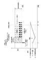
図2は実施例1のバッテリヒータ作動中におけるバッテリ温度とバッテリヒータの消費電力挙動を示すタイムチャートである。走行終了時点では、走行中の放電によるバッテリ11の発熱によって外気温度よりもバッテリ11の温度が高くなる。その後、車両を放置している間は、バッテリ11の温度は、外気温度に向かって次第に低下していく。外気温度が極低温の場合は、前述したようにバッテリ11の性能低下温度やバッテリ内の電解質凍結温度に相当するバッテリ性能保証限界温度に達するのを防止するため、バッテリヒータ15によりバッテリ加熱を行う。
FIG. 2 is a time chart showing the battery temperature and the power consumption behavior of the battery heater during operation of the battery heater according to the first embodiment. At the end of traveling, the temperature of the
バッテリヒータ15は、通常、ヒータ作動開始温度と、このヒータ作動開始温度よりも高いヒータ作動停止温度が予め設定されている。バッテリ温度センサ14により検知されたバッテリ11の温度が作動開始温度に達すると、バッテリヒータ15を作動開始し、作動停止温度まで昇温した時点でバッテリヒータ15の作動を停止する。これにより、バッテリ11を所定温度以上に保持する。バッテリヒータ15が小出力型の場合、バッテリヒータ作動開始温度から作動停止温度に上昇するまで、通常は数時間かかり、また、バッテリ温度が作動停止温度から作動開始温度に冷えるまで通常は数時間を要する。また、バッテリヒータ15の作動は、バッテリ温度に基づいて行われるものであり、バッテリ11の充電状態等とは独立して行われる。よって、充電システム側では、充電システムのスリープ状態であっても、定期的に、又は不定期的にバッテリヒータ15の作動状態をチェックする必要がある。
The battery heater 15 is normally preset with a heater operation start temperature and a heater operation stop temperature higher than the heater operation start temperature. When the temperature of the
図3は実施例1の充電制御装置において実施されるタイマ充電時制御処理を表すフローチャートである。
ステップS1では、タイマ充電時間帯の予約の有無を判断し、予約がないときは本制御フローを終了し、予約があるときはステップS2へ進む。
ステップS2では、バッテリヒータ作動時の充電電力量不足分を計算する。具体的には、バッテリヒータ15の消費電力×充電時間で得られる消費電力量を計算する。
ステップS3では、計算された消費電力量を充電するための時間である必要充電時間延長量を決定する。
ステップS4では、予め設定されていた充電開始時刻を必要充電時間延長量分だけ早めた時刻を、バッテリヒータ15の作動状態チェック時刻として設定する。
ステップS5では、バッテリヒータ15の作動状態チェック時刻に到達したか否かを判断し、到達したと判断したときはステップS6に進み、それ以外のときは本ステップを繰り返す。尚、このとき、充電システムはスリープ状態であり、チェック時刻に到達すると、充電システムを起動して各種チェックを行う。
ステップS6では、充電システムを起動してバッテリヒータ15の作動状態をチェックし、バッテリヒータ15が作動中であればステップS8に進んで充電を開始し、停止中であればステップS7に進む。言い換えると、充電システムを起動する前のスリープ状態では、タイマのカウントによってチェック時刻に到達したか否かを判定しており、種々の状態チェックを行うメインの充電システムは起動していない。よって、充電システムのスリープ状態では、消費電力が極めて小さな状態とされる。
ステップS7では、予め設定されていた充電開始時刻に到達したか否かを判断し、到達したと判断したときはステップS8に進んで充電を開始し、到達していないときは本ステップを繰り返す。
FIG. 3 is a flowchart showing a timer charging control process performed in the charging control apparatus according to the first embodiment.
In step S1, it is determined whether or not there is a reservation for the timer charging time zone. If there is no reservation, this control flow is terminated, and if there is a reservation, the process proceeds to step S2.
In step S2, the amount of charging power shortage when the battery heater is activated is calculated. Specifically, the power consumption obtained by the power consumption of the battery heater 15 × the charging time is calculated.
In step S3, a required charge time extension amount that is a time for charging the calculated power consumption is determined.
In step S <b> 4, a time obtained by advancing the preset charging start time by the required charging time extension amount is set as the operating state check time of the battery heater 15.
In step S5, it is determined whether or not the operating state check time of the battery heater 15 has been reached. When it is determined that the time has been reached, the process proceeds to step S6, and in other cases, this step is repeated. At this time, the charging system is in a sleep state, and when the check time is reached, the charging system is activated to perform various checks.
In step S6, the charging system is activated to check the operating state of the battery heater 15. If the battery heater 15 is in operation, the process proceeds to step S8 to start charging, and if it is stopped, the process proceeds to step S7. In other words, in the sleep state before starting the charging system, it is determined whether the check time has been reached by counting the timer, and the main charging system that performs various state checks is not started. Therefore, the power consumption is extremely small in the sleep state of the charging system.
In step S7, it is determined whether or not a preset charging start time has been reached. If it is determined that the charging has started, the process proceeds to step S8 to start charging, and if not reached, this step is repeated.
図4は実施例1のタイマ充電時制御処理を表すタイムチャートである。このタイムチャートの最初の状態は、ユーザが外部電源50と電動車両100とを充電ケーブル40により接続し、ユーザがインターフェース装置25により充電開始時刻と充電停止時刻とを設定した場合を示す。また、外部電源50により供給可能な電力には制限があり、この制限内で電力供給を行うものである。このとき、外気温はバッテリ性能保障限界温度よりも低く、言い換えると、バッテリ11の温度は放置によりヒータ作動停止温度を下回る。
FIG. 4 is a time chart illustrating the control process during timer charging according to the first embodiment. The initial state of this time chart shows a case where the user connects the
時刻t1において、バッテリ温度がヒータ作動停止温度を下回ると、バッテリヒータ15が作動し、バッテリ11を暖め始める。このときは、まだ充電開始時刻よりも前の段階である。尚、充電制御装置21では、ユーザにより充電開始時刻と充電停止時刻が設定された段階で、仮に、その間ずっとバッテリヒータ15が作動した場合に必要な必要充電時間延長量を計算し、予め設定されていた充電開始時刻よりも手前側に前倒ししたバッテリヒータ15の作動状態チェック時刻を設定する。
When the battery temperature falls below the heater operation stop temperature at time t1, the battery heater 15 operates and starts to warm the
時刻t2において、作動状態チェック時刻に到達したときにバッテリヒータ15が作動している場合には、即座に充電を開始する。よって、作動状態チェック時刻は、言い換えると前倒しした充電開始時刻である。これにより、バッテリヒータ15の作動により不足する充電電力量を補完することができる。 If the battery heater 15 is operating when the operating state check time is reached at time t2, charging is immediately started. Therefore, the operation state check time is, in other words, the charge start time that is advanced. As a result, the amount of charging power that is insufficient due to the operation of the battery heater 15 can be supplemented.
時刻t3において、時刻t2から既に充電が開始されているため、充電開始時刻以降も継続的にバッテリヒータ15が作動したとしても、満充電となるタイミングが充電停止時刻以降となることがない。言い換えると、バッテリヒータ15が作動したとしても、充電停止時刻において満充電状態を達成することができる。 Since charging has already started from time t2 at time t3, even if the battery heater 15 is continuously operated after the charging start time, the timing of full charge will not be after the charging stop time. In other words, even when the battery heater 15 is activated, the fully charged state can be achieved at the charging stop time.
以上、実施例1は、下記に列挙する作用効果を得ることができる。
(1)電気を充放電するバッテリ11と、バッテリ11を加熱するバッテリヒータ15と、バッテリ11の温度を検知するバッテリ温度センサ14(バッテリ温度検出手段)と、バッテリ11の温度状態を監視してバッテリヒータ15を制御してバッテリ加熱を行うバッテリ制御装置12(バッテリ制御手段)と、バッテリ11及びバッテリヒータ15に電力を供給する充電器22と、ユーザが所定の充電時間帯と目標充電量を任意に指定可能なインターフェース装置25(タイマ充電予約手段)と、インターフェース装置25により指定時刻までにタイマ充電を完了する指定が成されたときは、タイマ充電開始時刻を決定し、タイマ充電を行う充電制御装置21(充電制御手段)と、を備え、充電制御装置21は、タイマ充電とバッテリ加熱とが同時に行われると予測したときは、指定時刻までに充電が完了するように必要充電時間延長量を決定し、その分だけタイマ充電開始時刻よりも早く充電を開始することとした。
As described above, Example 1 can obtain the following effects.
(1) A
すなわち、タイマ充電とバッテリ加熱とが同時に行われることにより充電電力が低下したとしても、充電開始時刻を早めることで充電時間を延長することができ、充電停止時刻において充電量不足を回避することができる。また、タイマ充電中にバッテリ加熱を行えるため、バッテリヒータ15の要求能力を高くする必要がなく、コストアップを回避することができる。また、充電中にバッテリヒータ15を作動させつつ充電を行うため、充電効率の低下を回避することができる。 That is, even if the charging power is reduced by performing timer charging and battery heating at the same time, the charging time can be extended by advancing the charging start time, and the shortage of the charging amount can be avoided at the charging stop time. it can. Further, since the battery can be heated during the timer charging, it is not necessary to increase the required capacity of the battery heater 15, and an increase in cost can be avoided. Further, since charging is performed while operating the battery heater 15 during charging, it is possible to avoid a decrease in charging efficiency.
(2)充電制御装置21は、タイマ充電開始時刻より必要充電時間延長量(所定時間)前において、バッテリ加熱が行われていた場合、タイマ充電とバッテリ加熱とが同時に行われると判断する。すなわち、バッテリ加熱が行われているということは、外気温が極めて低い状況が想定され、バッテリ11の温度の再度の低下を回避するためにバッテリヒータ15が作動する可能性が高い。そこで、タイマ充電とバッテリ加熱が同時に行われると判断しておけば、仮にバッテリヒータ15が作動していない状況があったとしても充電量が不足することがない。よって、充電停止時刻において充電量が不足することを回避することができる。
(2) When the battery heating is performed before the necessary charging time extension amount (predetermined time) before the timer charging start time, the charging
〔実施例2〕
次に、実施例2について説明する。基本的な構成は実施例1と同じであるため、異なる点についてのみ説明する。図5は実施例2の充電制御装置において実施されるタイマ充電時制御処理を表すフローチャートである。実施例1ではバッテリヒータ15の作動の有無に基づいてタイマ充電開始時刻を早めるか否かを判断したが、実施例2ではバッテリ温度に基づいてタイマ充電開始時刻を早めるか否かを判断する点が異なる。
[Example 2]
Next, Example 2 will be described. Since the basic configuration is the same as that of the first embodiment, only different points will be described. FIG. 5 is a flowchart showing a timer charging control process performed in the charge control device of the second embodiment. In the first embodiment, it is determined whether or not the timer charging start time is advanced based on whether or not the battery heater 15 is operated. In the second embodiment, it is determined whether or not the timer charging start time is advanced based on the battery temperature. Is different.
ステップS1では、タイマ充電時間帯の予約の有無を判断し、予約がないときは本制御フローを終了し、予約があるときはステップS2へ進む。
ステップS2では、バッテリヒータ作動時の充電電力量不足分を計算する。具体的には、バッテリヒータ15の消費電力×充電時間で得られる消費電力量を計算する。
ステップS3では、計算された消費電力量を充電するための時間である必要充電時間延長量を決定する。
ステップS41では、予め設定されていた充電開始時刻を必要充電時間延長量分だけ早めた時刻を、バッテリ温度のチェック時刻として設定する。
ステップS51では、バッテリ温度のチェック時刻に到達したか否かを判断し、到達したと判断したときはステップS61に進み、それ以外のときは本ステップを繰り返す。尚、このとき、充電システムはスリープ状態であり、チェック時刻に到達すると、充電システムを起動して各種チェックを行う。
ステップS61では、バッテリ温度をチェックし、バッテリ温度が閾値であるヒータ作動停止温度以下であればステップS8に進んで充電を開始し、停止中であればステップS7に進む。
ステップS7では、予め設定されていた充電開始時刻に到達したか否かを判断し、到達したと判断したときはステップS8に進んで充電を開始し、到達していないときは本ステップを繰り返す。
In step S1, it is determined whether or not there is a reservation for the timer charging time zone. If there is no reservation, this control flow is terminated, and if there is a reservation, the process proceeds to step S2.
In step S2, the amount of charging power shortage when the battery heater is activated is calculated. Specifically, the power consumption obtained by the power consumption of the battery heater 15 × the charging time is calculated.
In step S3, a required charge time extension amount that is a time for charging the calculated power consumption is determined.
In step S41, a time obtained by advancing the preset charging start time by the required charging time extension amount is set as the battery temperature check time.
In step S51, it is determined whether or not the battery temperature check time has been reached. If it is determined that the battery temperature has been reached, the process proceeds to step S61. Otherwise, this step is repeated. At this time, the charging system is in a sleep state, and when the check time is reached, the charging system is activated to perform various checks.
In step S61, the battery temperature is checked. If the battery temperature is equal to or lower than the heater operation stop temperature that is the threshold value, the process proceeds to step S8 to start charging, and if it is stopped, the process proceeds to step S7.
In step S7, it is determined whether or not a preset charging start time has been reached. If it is determined that the charging has started, the process proceeds to step S8 to start charging, and if not reached, this step is repeated.
図6は実施例2のタイマ充電時制御処理を表すタイムチャートである。このタイムチャートの最初の状態は、ユーザが外部電源50と電動車両100とを充電ケーブル40により接続し、ユーザがインターフェース装置25充電開始時刻と充電停止時刻とを設定した場合を示す。また、外部電源50により供給可能な電力には制限があり、この制限内で電力供給を行うものである。このとき、外気温はバッテリ性能保障限界温度よりも低く、言い換えると、バッテリ11の温度は放置によりヒータ作動停止温度を下回る。
FIG. 6 is a time chart illustrating the control process during timer charging according to the second embodiment. The initial state of this time chart shows a case where the user connects the
まず、充電制御装置21では、ユーザにより充電開始時刻と充電停止時刻が設定された段階で、仮に、その間ずっとバッテリヒータ15が作動した場合に必要な必要充電時間延長量を計算し、予め設定されていた充電開始時刻よりも手前側に前倒ししたバッテリ温度のチェック時刻を設定する。
First, in the
時刻t1において、バッテリ温度のチェック時刻に到達したときにバッテリ温度がヒータ作動停止温度以下の場合には、充電中にバッテリヒータ15が作動する可能性が高いと判断し、即座に充電を開始する。よって、バッテリ温度のチェック時刻は、言い換えると前倒しした充電開始時刻である。これにより、バッテリヒータ15の作動により不足する充電電力量を補完することができる。 If the battery temperature is equal to or lower than the heater operation stop temperature when the battery temperature check time is reached at time t1, it is determined that the battery heater 15 is likely to operate during charging, and charging is immediately started. . Therefore, the check time of the battery temperature is, in other words, the charge start time brought forward. As a result, the amount of charging power that is insufficient due to the operation of the battery heater 15 can be supplemented.
時刻t2において、時刻t1から既に充電が開始されているため、充電開始時刻以降も継続的にバッテリヒータ15が作動したとしても、満充電となるタイミングが充電停止時刻以降となることがない。言い換えると、バッテリヒータ15が作動したとしても、充電停止時刻において満充電状態を達成することができる。その後、時刻t3において、バッテリ温度がヒータ作動停止温度に到達すると、バッテリヒータ15の作動が停止する。 At time t2, since charging has already been started from time t1, even when the battery heater 15 is continuously operated after the charging start time, the timing of full charge will not be after the charging stop time. In other words, even when the battery heater 15 is activated, the fully charged state can be achieved at the charging stop time. Thereafter, when the battery temperature reaches the heater operation stop temperature at time t3, the operation of the battery heater 15 is stopped.
以上説明したように、実施例2にあっては下記の作用効果を得ることができる。
(3)充電制御装置21は、タイマ充電開始時刻より必要充電時間延長量(所定時間)前において、バッテリ温度がヒータ作動停止温度(所定値)以下の場合、タイマ充電とバッテリ加熱とが同時に行われると判断する。
すなわち、タイマ充電開始時刻より必要充電時間延長量だけ前の段階において、既にバッテリ加熱が行われていた場合には、当然バッテリ温度はヒータ作動停止温度以下の状態であり、その後もバッテリヒータ15が作動する蓋然性が高い。一方、バッテリ加熱が行われていなくても、バッテリ温度がヒータ作動停止温度以下のときは、その後、ヒータ作動開始温度まで低下する可能性が高く、その場合にはバッテリヒータ15が作動する。そこで、タイマ充電とバッテリ加熱が同時に行われると判断しておけば、仮にバッテリヒータ15が作動していない状況があったとしても充電量が不足することがない。よって、充電停止時刻において充電量が不足することを回避することができる。
As described above, in the second embodiment, the following operational effects can be obtained.
(3) When the battery temperature is equal to or lower than the heater operation stop temperature (predetermined value) before the required charging time extension amount (predetermined time) from the timer charging start time, the charging
That is, if battery heating has already been performed at a stage before the required charging time extension from the timer charging start time, the battery temperature is naturally below the heater operation stop temperature. High probability of operation. On the other hand, even if the battery is not heated, when the battery temperature is equal to or lower than the heater operation stop temperature, there is a high possibility that the battery heater 15 will subsequently decrease to the heater operation start temperature. In this case, the battery heater 15 operates. Therefore, if it is determined that timer charging and battery heating are performed at the same time, even if there is a situation where the battery heater 15 is not operating, the amount of charge will not be insufficient. Therefore, it is possible to avoid a shortage of the charge amount at the charge stop time.
〔実施例3〕
次に、実施例3について説明する。基本的な構成は実施例1と同じであるため、異なる点についてのみ説明する。図7は実施例3の充電制御装置において実施されるタイマ充電時制御処理を表すフローチャートである。実施例1,2では、タイマ充電開始時刻から早める時間である必要充電時間延長量を充電中に継続的にバッテリヒータ15が作動した場合に基づいて設定した。すなわち、必要充電時間延長量だけ前倒しした時刻と作動状態やバッテリ温度のチェック時刻とは一致していた。これに対し、実施例3では、バッテリヒータ15の作動を精度よく推定し、この推定される作動状態に基づいて必要充電時間延長量を演算する点が異なる。
Example 3
Next, Example 3 will be described. Since the basic configuration is the same as that of the first embodiment, only different points will be described. FIG. 7 is a flowchart showing a timer charging control process performed in the charging control apparatus according to the third embodiment. In Examples 1 and 2, the required charge time extension amount, which is a time that is advanced from the timer charging start time, is set based on the case where the battery heater 15 is continuously operated during charging. That is, the time when the advance of the necessary charging time is advanced coincides with the check time of the operating state and the battery temperature. In contrast, the third embodiment is different in that the operation of the battery heater 15 is accurately estimated and the required charging time extension amount is calculated based on the estimated operation state.
ステップS1では、タイマ充電時間帯の予約の有無を判断し、予約がないときは本制御フローを終了し、予約があるときはステップS22へ進む。
ステップS22では、バッテリ温度と、外気温度と、バッテリヒータ作動状態とをチェックするチェック時刻を設定する。このチェック時刻は、バッテリヒータ15の消費電力×充電時間で得られる消費電力量を計算し、計算された消費電力量を充電するための時間だけ、タイマ充電開始時刻よりも早めたタイミングである。
ステップS32では、チェック時刻に到達したか否かを判断し、到達したと判断したときはステップS42に進み、それ以外のときは本ステップを繰り返す。尚、このとき、充電システムはスリープ状態であり、チェック時刻に到達すると、充電システムを起動して各種チェックを行う。
ステップS42では、バッテリ温度推移を予測する。具体的には、チェック時刻におけるバッテリ温度を初期値とし、外気温度相当まで低下するときの温度低下特性演算式等を設定しておく。そして、何時間後にバッテリ温度がヒータ作動開始温度まで低下するかを予測演算する。逆に、バッテリヒータ15が作動した後は、更に何時間後にバッテリ温度がヒータ作動停止温度まで上昇するかを予測演算する。これにより、タイマ充電とバッテリ加熱が同時に行われるタイミングを含めて予測することができる。
In step S1, it is determined whether or not there is a reservation for the timer charging time zone. If there is no reservation, this control flow is terminated, and if there is a reservation, the process proceeds to step S22.
In step S22, a check time for checking the battery temperature, the outside air temperature, and the battery heater operating state is set. This check time is a timing that is earlier than the timer charging start time by a time for calculating the power consumption obtained by the power consumption of the battery heater 15 × the charging time and charging the calculated power consumption.
In step S32, it is determined whether or not the check time has been reached. If it is determined that the check time has been reached, the process proceeds to step S42, and if not, this step is repeated. At this time, the charging system is in a sleep state, and when the check time is reached, the charging system is activated to perform various checks.
In step S42, battery temperature transition is predicted. Specifically, the battery temperature at the check time is set as an initial value, and an equation for calculating a temperature drop characteristic when the battery temperature falls to the outside air temperature is set. Then, how many hours later the battery temperature is reduced to the heater operation start temperature is predicted. On the other hand, after the battery heater 15 is activated, a prediction calculation is made as to how many hours later the battery temperature rises to the heater operation stop temperature. Thereby, it can estimate including the timing in which timer charge and battery heating are performed simultaneously.
ステップS52では、タイマ充電時間帯にバッテリヒータ15が作動すると予測したか否か、すなわち、タイマ充電時間帯に推定されたバッテリ温度がヒータ作動開始温度以下となるか否かを判断し、以下となると予測した場合にはステップS62に進む。一方、以下とならないと予測した場合にはステップS102に進んで予め設定されていたタイマ充電開始時刻に到達したか否かを判断し、到達したと判断したときはステップS92に進んで充電を開始し、到達していないと判断したときは到達するまでステップS102を繰り返す。 In step S52, it is determined whether or not the battery heater 15 is predicted to operate during the timer charging time period, that is, whether or not the battery temperature estimated during the timer charging time period is equal to or lower than the heater operation start temperature. If it is predicted that this will occur, the process proceeds to step S62. On the other hand, if it is predicted that the following will not occur, the process proceeds to step S102 to determine whether or not the preset timer charging start time has been reached, and if it has been determined, the process proceeds to step S92 to start charging. However, if it is determined that it has not been reached, step S102 is repeated until it is reached.
ステップS62では、タイマ充電時間帯のバッテリヒータ作動による充電電力量不足分を計算する。具体的には、予測されたバッテリ温度に基づいてバッテリヒータ15が作動すると予測される作動予測時間を演算する。そして、バッテリヒータ15の消費電力×作動予測時間で得られる消費電力量を充電電力量不足分として決定する。
ステップS72では、必要充電時間延長量を決定し、予め設定されたタイマ充電開始時刻から必要充電時間延長量だけ前倒ししたタイマ充電前倒し時刻を設定する。具体的には、充電電力量不足分を補うことができる時間を決定する。
ステップS82では、タイマ充電前倒し時刻に到達したか否かを判断し、到達したと判断したときはステップS92に進んで充電を開始し、到達していないと判断したときは本ステップを繰り返す。
In step S62, the shortage of the amount of charging power due to the battery heater operation in the timer charging time zone is calculated. Specifically, a predicted operation time at which the battery heater 15 is predicted to operate is calculated based on the predicted battery temperature. Then, the amount of power consumed obtained by the power consumption of the battery heater 15 multiplied by the estimated operation time is determined as the insufficient amount of charge power.
In step S72, a necessary charge time extension amount is determined, and a timer charge advance time that is advanced by a necessary charge time extension amount from a preset timer charge start time is set. Specifically, the time that can compensate for the shortage of the charging power amount is determined.
In step S82, it is determined whether or not the timer charging advance time has been reached. When it is determined that the timer charging has been reached, the process proceeds to step S92 to start charging, and when it is determined that the timer charging has not been reached, this step is repeated.
図8は実施例3のタイマ充電時制御処理を表すタイムチャートである。このタイムチャートの最初の状態は、ユーザが外部電源50と電動車両100とを充電ケーブル40により接続し、ユーザがインターフェース装置25充電開始時刻と充電停止時刻とを設定した場合を示す。また、外部電源50により供給可能な電力には制限があり、この制限内で電力供給を行うものである。このとき、外気温はバッテリ性能保障限界温度よりも低く、言い換えると、バッテリ11の温度は放置によりヒータ作動停止温度を下回る。
FIG. 8 is a time chart showing the control process during timer charging according to the third embodiment. The initial state of this time chart shows a case where the user connects the
まず、充電制御装置21では、ユーザにより充電開始時刻と充電停止時刻が設定された段階で、仮に、その間ずっとバッテリヒータ15が作動した場合に必要な充電時間延長量を計算し、予め設定されていた充電開始時刻よりも手前側に前倒ししたバッテリ温度,外気温度,バッテリヒータ作動状態のチェック時刻を設定する。
First, in the charging
時刻t1において、バッテリ温度のチェック時刻に到達したときにバッテリ温度推移を予測する。このとき、タイマ充電時間帯である時刻t3から時刻t4においてバッテリヒータ15が作動すると予測できるため、この時刻t3から時刻t4までの間に消費される電力に相当する必要充電時間延長量を演算する。そして、予め設定されていた充電開始時刻から必要充電時間延長量だけ前倒ししたタイマ充電前倒し時刻を設定する。これにより、バッテリヒータ15の作動により不足する充電電力量を補完することができる。 At time t1, the battery temperature transition is predicted when the battery temperature check time is reached. At this time, since it can be predicted that the battery heater 15 operates from the time t3 to the time t4, which is the timer charging time zone, a necessary charge time extension amount corresponding to the power consumed from the time t3 to the time t4 is calculated. . Then, a timer charge advance time that is advanced by a necessary charge time extension amount from a preset charge start time is set. As a result, the amount of charging power that is insufficient due to the operation of the battery heater 15 can be supplemented.
時刻t2において、タイマ充電前倒し時刻に到達すると、タイマ充電を開始する。そして、時刻t3においてバッテリヒータ15が作動するものの、満充電となるタイミングが充電停止時刻である時刻t4以降となることがない。言い換えると、バッテリヒータ15が作動したとしても、充電停止時刻t4において満充電状態を達成することができる。その後、時刻t5において、バッテリ温度がヒータ作動停止温度に到達すると、バッテリヒータ15の作動が停止する。 When the timer charging advance time is reached at time t2, timer charging is started. And although the battery heater 15 operates at the time t3, the full charge timing does not become after the time t4 which is the charge stop time. In other words, even when the battery heater 15 is activated, the fully charged state can be achieved at the charging stop time t4. Thereafter, when the battery temperature reaches the heater operation stop temperature at time t5, the operation of the battery heater 15 is stopped.
以上説明したように、実施例3にあっては下記の作用効果を得ることができる。
(4)外気温度を検知する外気温度センサ26(外気温度検出手段)を有し、充電制御装置21は、タイマ充電開始時刻より所定時間前であるチェック時刻において、その時点のバッテリヒータ作動状態とバッテリ温度と外気温度とから、タイマ充電時間帯におけるバッテリ温度推移を予測し、予測されたバッテリ温度が予め設定されたバッテリヒータ作動温度範囲にあると予測した場合、タイマ充電とバッテリ加熱とが同時に行われると判断することとした。
As described above, the following operational effects can be obtained in the third embodiment.
(4) It has an outside air temperature sensor 26 (outside air temperature detecting means) for detecting the outside air temperature, and the
すなわち、既にバッテリ加熱が行われているときは、バッテリヒータ15の出力と現在のバッテリ温度と外気温度とから、その後のバッテリ温度推移を予測し、タイマ充電開始後もバッテリヒータ15の作動が継続するかどうかを判断できる。また、バッテリ加熱が行われていないときは、現在のバッテリ温度と外気温度とからバッテリ温度変化を予測できるため、タイマ充電開始後にバッテリヒータ15が作動するかどうかを判断できる。 That is, when the battery is already heated, the subsequent battery temperature transition is predicted from the output of the battery heater 15, the current battery temperature, and the outside air temperature, and the operation of the battery heater 15 continues even after the timer charging is started. You can decide whether to do it. Further, when the battery is not heated, a change in the battery temperature can be predicted from the current battery temperature and the outside air temperature. Therefore, it can be determined whether or not the battery heater 15 is activated after the timer charging is started.
(5)充電制御装置21は、予測されたバッテリ温度に基づいてタイマ充電時間帯におけるバッテリヒータ作動時間及び消費電力を予測演算し、必要充電時間延長量を決定する。すなわち、バッテリヒータ15がタイマ充電時間帯の一部だけ作動した場合、その分の消費電力量だけ充電開始時刻を前倒しするため、充電開始時刻を前倒ししすぎることがなく、ユーザが指定した充電停止時刻通りに充電を完了することができる。
(5) The charging
〔実施例4〕
次に、実施例4について説明する。基本的な構成は実施例1,2と同じであるため異なる点についてのみ説明する。図9は実施例4の充電制御装置において実施されるタイマ充電時制御処理を表すフローチャートである。実施例1,2では、タイマ充電開始時刻から必要充電時間延長量だけ早めた時刻において、バッテリヒータ15の作動状態もしくはバッテリ温度の一方のみをチェックしていた。これに対し、実施例4では、バッテリヒータ15の作動状態及びバッテリ温度の両方をチェックする点が異なる。
Example 4
Next, Example 4 will be described. Since the basic configuration is the same as in the first and second embodiments, only different points will be described. FIG. 9 is a flowchart illustrating a control process at the time of timer charging performed in the charging control apparatus according to the fourth embodiment. In the first and second embodiments, only the operating state of the battery heater 15 or the battery temperature is checked at a time earlier than the timer charging start time by the required charging time extension amount. In contrast, the fourth embodiment is different in that both the operating state of the battery heater 15 and the battery temperature are checked.
ステップS1では、タイマ充電時間帯の予約の有無を判断し、予約がないときは本制御フローを終了し、予約があるときはステップS2へ進む。
ステップS2では、バッテリヒータ作動時の充電電力量不足分を計算する。具体的には、バッテリヒータ15の消費電力×充電時間で得られる消費電力量を計算する。
ステップS3では、計算された消費電力量を充電するための時間である必要充電時間延長量を決定する。
ステップS4では、予め設定されていた充電開始時刻を必要充電時間延長量分だけ早めた時刻を、バッテリヒータ15の作動状態及びバッテリ温度のチェック時刻として設定する。
ステップS54では、バッテリヒータ15の作動状態チェック時刻に到達したか否かを判断し、到達したと判断したときはステップS6に進み、それ以外のときは本ステップを繰り返す。尚、このとき、充電システムはスリープ状態であり、チェック時刻に到達すると、充電システムを起動して各種チェックを行う。
ステップS6では、バッテリヒータ15の作動状態をチェックし、バッテリヒータ15が作動中であればステップS602に進み、停止中の時はステップS601に進む。
In step S1, it is determined whether or not there is a reservation for the timer charging time zone. If there is no reservation, this control flow is terminated, and if there is a reservation, the process proceeds to step S2.
In step S2, the amount of charging power shortage when the battery heater is activated is calculated. Specifically, the power consumption obtained by the power consumption of the battery heater 15 × the charging time is calculated.
In step S3, a required charge time extension amount that is a time for charging the calculated power consumption is determined.
In step S4, the time when the preset charging start time is advanced by the required charging time extension amount is set as the operating state of the battery heater 15 and the battery temperature check time.
In step S54, it is determined whether or not the operating state check time of the battery heater 15 has been reached. When it is determined that the time has been reached, the process proceeds to step S6, and in other cases, this step is repeated. At this time, the charging system is in a sleep state, and when the check time is reached, the charging system is activated to perform various checks.
In step S6, the operating state of the battery heater 15 is checked. If the battery heater 15 is operating, the process proceeds to step S602, and if it is stopped, the process proceeds to step S601.
ステップS601では、バッテリ温度が第1閾値以下か否かを判断し、第1閾値以下のときは、これからバッテリヒータ15が作動する蓋然性が高いと判断し、ステップS8に進んで充電を開始する。一方、第1閾値よりも大きいときは、まだバッテリヒータ15が作動する蓋然性は低いと判断してステップS7に進む。ここで、第1閾値は、ヒータ作動開始温度よりも高く、ヒータ作動停止温度よりも低い所定値である。
ステップS602では、バッテリ温度が第2閾値以下か否かを判断し、第2閾値より高いときはバッテリヒータ15の作動が停止する蓋然性が高いと判断してステップS7に進む。一方、第2閾値以下のときは、まだバッテリヒータ15の作動が継続する蓋然性が高いと判断し、ステップS8に進んで充電を開始する。ここで、第2閾値は、ヒータ作動開始温度よりも高く、ヒータ作動停止温度よりも低い所定値であり、第1閾値よりも高い値に設定されている。
ステップS7では、予め設定されていた充電開始時刻に到達したか否かを判断し、到達したと判断したときはステップS8に進んで充電を開始し、到達していないときは本ステップを繰り返す。
In step S601, it is determined whether or not the battery temperature is equal to or lower than the first threshold value. When the battery temperature is equal to or lower than the first threshold value, it is determined that the probability that the battery heater 15 will be activated is high. On the other hand, when it is larger than the first threshold, it is determined that the probability that the battery heater 15 is still operating is low, and the process proceeds to step S7. Here, the first threshold value is a predetermined value that is higher than the heater operation start temperature and lower than the heater operation stop temperature.
In step S602, it is determined whether or not the battery temperature is equal to or lower than a second threshold value. If the battery temperature is higher than the second threshold value, it is determined that there is a high probability that the operation of the battery heater 15 is stopped, and the process proceeds to step S7. On the other hand, when it is equal to or less than the second threshold value, it is determined that the probability that the operation of the battery heater 15 is still continued is high, and the process proceeds to step S8 to start charging. Here, the second threshold value is a predetermined value that is higher than the heater operation start temperature and lower than the heater operation stop temperature, and is set to a value higher than the first threshold value.
In step S7, it is determined whether or not a preset charging start time has been reached. If it is determined that the charging has started, the process proceeds to step S8 to start charging, and if not reached, this step is repeated.
以上説明したように、実施例4にあっては、バッテリヒータ15の停止中であっても、バッテリ温度が第1閾値以下のときは充電を開始することで、より確実に充電量不足を回避することができる。また、バッテリヒータ15の作動中であっても、バッテリ温度が第2閾値より高いときは充電を開始しないため、不要な充電を回避することができる。 As described above, in the fourth embodiment, even when the battery heater 15 is stopped, when the battery temperature is equal to or lower than the first threshold value, charging is started more reliably to avoid insufficient charge. can do. Even when the battery heater 15 is in operation, charging is not started when the battery temperature is higher than the second threshold value, so unnecessary charging can be avoided.
以上、各実施例に基づいて本発明を説明したが、上記構成に限られず本発明の範囲を逸脱しない範囲で他の構成を取り得る。実施例1では、電動車両について説明したが、プラグインハイブリッド型の車両であってもよい。また、実施例では演算された必要充電時間延長量だけ充電開始時刻を早める構成としたが、更に確実に充電を完了するために安全率を考慮してマージンを加算した時間だけ前倒ししてもよい。 As described above, the present invention has been described based on each embodiment. However, the present invention is not limited to the above-described configuration, and other configurations can be taken without departing from the scope of the present invention. Although the electric vehicle has been described in the first embodiment, it may be a plug-in hybrid type vehicle. In the embodiment, the charging start time is advanced by the calculated required charging time extension amount. However, in order to complete the charging more reliably, the margin may be advanced in consideration of the safety factor. .
実施例3では、チェック時刻において検出されたバッテリ温度に基づいてバッテリ温度推移を予測したが、チェック時刻より前のタイミングで複数回バッテリ温度のサンプリングを取り、このサンプリングの温度推移からバッテリ温度推移を予測する構成としてもよい。 In the third embodiment, the battery temperature transition is predicted based on the battery temperature detected at the check time. However, the battery temperature is sampled a plurality of times at the timing before the check time, and the battery temperature transition is calculated from the temperature transition of the sampling. It is good also as a structure to predict.
11 バッテリ
12 バッテリ制御装置
14 バッテリ温度センサ
15 バッテリヒータ
21 充電制御装置
22 充電器
25 インターフェース装置
26 外気温度センサ
40 充電ケーブル
50 外部電源
100 電動車両
DESCRIPTION OF
Claims (5)
前記バッテリを加熱するバッテリヒータと、
前記バッテリの温度を検知するバッテリ温度検出手段と、
前記バッテリの温度状態を監視して前記バッテリヒータを制御してバッテリ加熱を行うバッテリ制御手段と、
前記バッテリ及び前記バッテリヒータに電力を供給する充電器と、
ユーザが所定の充電時間帯と目標充電量を任意に指定可能なタイマ充電予約手段と、
前記タイマ充電予約手段により指定時刻までにタイマ充電を完了する指定が成されたときは、タイマ充電開始時刻を決定し、タイマ充電を行う充電制御手段と、
を備え、
前記充電制御手段は、タイマ充電とバッテリ加熱とが同時に行われると予測したときは、前記指定時刻までに充電が完了するように必要充電時間延長量を決定し、その分だけ前記タイマ充電開始時刻よりも早く充電を開始することを特徴とする車両の充電制御装置。 A battery that charges and discharges electricity;
A battery heater for heating the battery;
Battery temperature detecting means for detecting the temperature of the battery;
Battery control means for monitoring the temperature state of the battery and controlling the battery heater to heat the battery;
A charger for supplying power to the battery and the battery heater;
Timer charging reservation means that allows a user to arbitrarily specify a predetermined charging time zone and a target charging amount;
When designation is made to complete timer charging by a designated time by the timer charge reservation means, a charge control means for determining a timer charge start time and performing timer charge;
With
When the charging control means predicts that the timer charging and the battery heating are performed simultaneously, it determines a necessary charging time extension amount so that the charging is completed by the designated time, and the timer charging start time is increased by that amount. A charging control device for a vehicle, characterized in that charging is started earlier.
前記充電制御手段は、前記タイマ充電開始時刻より所定時間前において、前記バッテリ加熱が行われていた場合、タイマ充電とバッテリ加熱とが同時に行われると判断することを特徴とする車両の充電制御装置。 In the vehicle charging control device according to claim 1,
The charging control device according to claim 1, wherein the charging control unit determines that the timer charging and the battery heating are performed simultaneously when the battery heating is performed a predetermined time before the timer charging start time. .
前記充電制御手段は、前記タイマ充電開始時刻より所定時間前において、前記バッテリ温度が所定値以下の場合、タイマ充電とバッテリ加熱とが同時に行われると判断することを特徴とする車両の充電制御装置。 In the vehicle charge control device according to claim 1 or 2,
The charging control device according to claim 1, wherein when the battery temperature is equal to or lower than a predetermined value before the timer charging start time, the charging control means determines that timer charging and battery heating are performed simultaneously. .
外気温度を検知する外気温度検出手段を有し、
前記充電制御手段は、前記タイマ充電開始時刻より所定時間前において、その時点のバッテリヒータ作動状態とバッテリ温度と外気温度とから、前記タイマ充電時間帯におけるバッテリ温度推移を予測し、前記予測されたバッテリ温度が予め設定されたバッテリヒータ作動温度範囲にあると予測した場合、タイマ充電とバッテリ加熱とが同時に行われると判断することを特徴とする車両の充電制御装置。 In the vehicle charging control device according to claim 1,
Having an outside air temperature detecting means for detecting the outside air temperature,
The charging control means predicts a battery temperature transition in the timer charging time zone from a battery heater operating state, a battery temperature, and an outside air temperature at a predetermined time before the timer charging start time, and the predicted A vehicle charge control device, wherein when the battery temperature is predicted to be within a preset battery heater operating temperature range, it is determined that timer charging and battery heating are performed simultaneously.
前記充電制御手段は、前記予測されたバッテリ温度に基づいてタイマ充電時間帯におけるバッテリヒータ作動時間及び消費電力を予測演算し、前記必要充電時間延長量を決定することを特徴とする車両の充電制御装置。 In the vehicle charging control device according to claim 4,
The charging control unit is configured to predict and calculate a battery heater operating time and power consumption in a timer charging time period based on the predicted battery temperature, and determine the required charging time extension amount. apparatus.
Priority Applications (6)
| Application Number | Priority Date | Filing Date | Title |
|---|---|---|---|
| JP2011054087A JP5668541B2 (en) | 2011-03-11 | 2011-03-11 | Vehicle charging control device |
| PCT/JP2012/055205 WO2012124486A1 (en) | 2011-03-11 | 2012-03-01 | Charge control device for vehicle |
| EP12758253.4A EP2685598B1 (en) | 2011-03-11 | 2012-03-01 | Charge control device for vehicle |
| CN201280002826.0A CN103098340B (en) | 2011-03-11 | 2012-03-01 | The battery charge controller of vehicle |
| US13/822,256 US9496734B2 (en) | 2011-03-11 | 2012-03-01 | Charge control apparatus for vehicle |
| KR1020137006185A KR101455550B1 (en) | 2011-03-11 | 2012-03-01 | Charge control apparatus for vehicle |
Applications Claiming Priority (1)
| Application Number | Priority Date | Filing Date | Title |
|---|---|---|---|
| JP2011054087A JP5668541B2 (en) | 2011-03-11 | 2011-03-11 | Vehicle charging control device |
Publications (2)
| Publication Number | Publication Date |
|---|---|
| JP2012191781A true JP2012191781A (en) | 2012-10-04 |
| JP5668541B2 JP5668541B2 (en) | 2015-02-12 |
Family
ID=46830561
Family Applications (1)
| Application Number | Title | Priority Date | Filing Date |
|---|---|---|---|
| JP2011054087A Active JP5668541B2 (en) | 2011-03-11 | 2011-03-11 | Vehicle charging control device |
Country Status (6)
| Country | Link |
|---|---|
| US (1) | US9496734B2 (en) |
| EP (1) | EP2685598B1 (en) |
| JP (1) | JP5668541B2 (en) |
| KR (1) | KR101455550B1 (en) |
| CN (1) | CN103098340B (en) |
| WO (1) | WO2012124486A1 (en) |
Cited By (8)
| Publication number | Priority date | Publication date | Assignee | Title |
|---|---|---|---|---|
| JP2012191784A (en) * | 2011-03-11 | 2012-10-04 | Nissan Motor Co Ltd | Vehicle charge control device |
| JP2015061337A (en) * | 2013-09-17 | 2015-03-30 | トヨタ自動車株式会社 | Device and method for controlling charging system |
| EP3037300A2 (en) | 2014-12-24 | 2016-06-29 | Toyota Jidosha Kabushiki Kaisha | Temperature-raising device and temperature-raising method for in-car battery |
| JP2017134571A (en) * | 2016-01-27 | 2017-08-03 | トヨタ自動車株式会社 | Charging system |
| EP3266641A1 (en) | 2016-07-04 | 2018-01-10 | Toyota Jidosha Kabushiki Kaisha | Battery charging system and battery charging method for electrically driven vehicle |
| CN110077281A (en) * | 2019-04-30 | 2019-08-02 | 浙江吉利控股集团有限公司 | A kind of charging heating method and system of plug-in hybrid electric vehicle power battery |
| KR102128322B1 (en) * | 2020-01-30 | 2020-06-30 | 쌍용자동차 주식회사 | Reservation charge control method of electric vehicle |
| JP7324136B2 (en) | 2019-12-12 | 2023-08-09 | 株式会社Subaru | Charging system and vehicle |
Families Citing this family (26)
| Publication number | Priority date | Publication date | Assignee | Title |
|---|---|---|---|---|
| JP5668542B2 (en) | 2011-03-11 | 2015-02-12 | 日産自動車株式会社 | Vehicle charging control device |
| JP5736860B2 (en) * | 2011-03-11 | 2015-06-17 | 日産自動車株式会社 | Battery charge control device |
| US8751085B2 (en) * | 2012-08-03 | 2014-06-10 | Chrysler Group Llc | Method and system for battery charging and thermal management control in electrified vehicles |
| CN103682498B (en) * | 2013-12-04 | 2016-03-02 | 华为终端有限公司 | A kind of charging method and electronic equipment |
| JP6028756B2 (en) * | 2014-03-19 | 2016-11-16 | トヨタ自動車株式会社 | Battery temperature control device |
| JP6090265B2 (en) | 2014-08-29 | 2017-03-08 | トヨタ自動車株式会社 | vehicle |
| CN104734307A (en) * | 2015-04-21 | 2015-06-24 | 中投仙能科技(苏州)有限公司 | Complementary direct-current power supply system for isolated grid |
| CN104967214B (en) * | 2015-06-04 | 2017-06-27 | 南京理工大学 | A kind of micro-grid system based on VACON industrial frequency transformers |
| CN105513807A (en) * | 2015-12-29 | 2016-04-20 | 中国电子科技集团公司第十一研究所 | Energy-storing capacitor device and laser power supply |
| KR101987527B1 (en) * | 2016-09-05 | 2019-06-10 | 현대자동차주식회사 | Method of controlling recharge schedule for electric vehicle |
| JP6493344B2 (en) * | 2016-09-12 | 2019-04-03 | トヨタ自動車株式会社 | Automobile |
| CN106877464A (en) * | 2017-04-24 | 2017-06-20 | 知谷(上海)网络科技有限公司 | Charge control method and charging equipment |
| CN110970687B (en) * | 2018-09-30 | 2021-05-14 | 比亚迪股份有限公司 | Power battery heating control method and device and vehicle |
| CN109624739B (en) * | 2018-12-17 | 2020-10-30 | 北京新能源汽车股份有限公司 | Electric automobile charging control method and device and automobile |
| CN110920464B (en) * | 2019-12-03 | 2021-04-30 | 神龙汽车有限公司 | Electric automobile charging coordination control method and electric automobile |
| CN111055722B (en) * | 2019-12-20 | 2023-11-17 | 华为技术有限公司 | Method, device and storage medium for estimating charging time |
| CN111175654B (en) * | 2020-01-13 | 2022-05-13 | 广州小鹏汽车科技有限公司 | Power battery charging remaining time calculation method and device, vehicle and storage medium |
| JP7310722B2 (en) | 2020-06-02 | 2023-07-19 | トヨタ自動車株式会社 | Power storage system and vehicle |
| CN114148219B (en) * | 2020-09-07 | 2023-05-26 | 宇通客车股份有限公司 | Method and device for controlling charging temperature of battery system |
| US20220094162A1 (en) * | 2020-09-21 | 2022-03-24 | Electronics And Telecommunications Research Institute | Demand management control method and apparatus for inducing dynamic participation of consumers in energy consumption loads management program |
| JP2022098779A (en) * | 2020-12-22 | 2022-07-04 | トヨタ自動車株式会社 | Server, vehicle, and method for vehicle diagnosis |
| CN112693364B (en) * | 2020-12-28 | 2022-05-24 | 宜宾凯翼汽车有限公司 | Power battery preheating and charging heat preservation control method |
| KR102377999B1 (en) * | 2021-08-09 | 2022-03-24 | 주식회사 퀀텀캣 | Method and system for providing battery information |
| CN114552068B (en) * | 2022-01-29 | 2024-04-26 | 北京新能源汽车股份有限公司 | Vehicle and power battery heating method and device thereof and storage medium |
| KR20230122936A (en) * | 2022-02-15 | 2023-08-22 | 주식회사 엘지에너지솔루션 | Battery management apparatus and operating method of the same |
| CN114290940B (en) * | 2022-03-09 | 2022-06-24 | 神龙汽车有限公司 | Delay charging control method for electric automobile |
Citations (4)
| Publication number | Priority date | Publication date | Assignee | Title |
|---|---|---|---|---|
| JPH0773906A (en) * | 1993-09-06 | 1995-03-17 | Kojima Press Co Ltd | Charging device for electric automobile |
| JPH08115747A (en) * | 1994-10-17 | 1996-05-07 | Nissan Motor Co Ltd | Charging system |
| JP2009136109A (en) * | 2007-11-30 | 2009-06-18 | Toyota Motor Corp | Charge control device and method |
| JP2012029491A (en) * | 2010-07-26 | 2012-02-09 | Nissan Motor Co Ltd | Motor-driven vehicle system |
Family Cites Families (22)
| Publication number | Priority date | Publication date | Assignee | Title |
|---|---|---|---|---|
| US5391974A (en) * | 1990-10-15 | 1995-02-21 | Toshiba Battery Co., Ltd. | Secondary battery charging circuit |
| US5329219A (en) | 1993-04-28 | 1994-07-12 | Motorola, Inc. | Method and apparatus for charging a battery |
| JP3554057B2 (en) | 1995-02-06 | 2004-08-11 | 本田技研工業株式会社 | Battery charging control device for electric vehicles |
| JPH11150885A (en) | 1997-11-17 | 1999-06-02 | Ricoh Co Ltd | Method for charging secondary battery |
| JP2000040536A (en) | 1998-07-23 | 2000-02-08 | Toyota Motor Corp | Battery warming up device |
| JP2002315204A (en) * | 2001-04-18 | 2002-10-25 | Matsushita Electric Ind Co Ltd | Charge controller |
| JP4636815B2 (en) * | 2004-05-26 | 2011-02-23 | 三洋電機株式会社 | Power supply for vehicle |
| JP4466656B2 (en) * | 2005-01-06 | 2010-05-26 | 日本電気株式会社 | Charge control device and charge control method for mobile phone terminal |
| JP5314235B2 (en) * | 2006-03-07 | 2013-10-16 | プライムアースEvエナジー株式会社 | Secondary battery temperature control device, secondary battery heating system, and program |
| JP4386057B2 (en) | 2006-08-10 | 2009-12-16 | ソニー株式会社 | Battery device |
| CN101622735A (en) * | 2007-01-05 | 2010-01-06 | 江森自控帅福得先进能源动力系统有限责任公司 | Battery module |
| JP4353283B2 (en) | 2007-06-18 | 2009-10-28 | トヨタ自動車株式会社 | Vehicle air conditioning control device |
| JP4228086B1 (en) * | 2007-08-09 | 2009-02-25 | トヨタ自動車株式会社 | vehicle |
| JP5321321B2 (en) | 2008-09-30 | 2013-10-23 | 日産自動車株式会社 | Battery charge control device and battery charge control method |
| US20100292855A1 (en) * | 2009-05-14 | 2010-11-18 | Michael Kintner-Meyer | Battery Charging Control Methods, Electrical Vehicle Charging Methods, Battery Charging Control Apparatus, and Electrical Vehicles |
| JP4932920B2 (en) * | 2010-02-12 | 2012-05-16 | 本田技研工業株式会社 | Charging equipment and charging system |
| JP2011238428A (en) | 2010-05-10 | 2011-11-24 | Kansai Electric Power Co Inc:The | Secondary battery charging system and charging method |
| JP2012016078A (en) * | 2010-06-29 | 2012-01-19 | Hitachi Ltd | Charging control system |
| JP5699702B2 (en) * | 2011-03-11 | 2015-04-15 | 日産自動車株式会社 | Vehicle charging control device |
| JP5668542B2 (en) * | 2011-03-11 | 2015-02-12 | 日産自動車株式会社 | Vehicle charging control device |
| JP5720322B2 (en) * | 2011-03-11 | 2015-05-20 | 日産自動車株式会社 | Battery temperature control device |
| US8890467B2 (en) | 2011-03-28 | 2014-11-18 | Continental Automotive Systems, Inc. | System for controlling battery conditions |
-
2011
- 2011-03-11 JP JP2011054087A patent/JP5668541B2/en active Active
-
2012
- 2012-03-01 WO PCT/JP2012/055205 patent/WO2012124486A1/en active Application Filing
- 2012-03-01 KR KR1020137006185A patent/KR101455550B1/en active IP Right Grant
- 2012-03-01 CN CN201280002826.0A patent/CN103098340B/en active Active
- 2012-03-01 EP EP12758253.4A patent/EP2685598B1/en active Active
- 2012-03-01 US US13/822,256 patent/US9496734B2/en active Active
Patent Citations (4)
| Publication number | Priority date | Publication date | Assignee | Title |
|---|---|---|---|---|
| JPH0773906A (en) * | 1993-09-06 | 1995-03-17 | Kojima Press Co Ltd | Charging device for electric automobile |
| JPH08115747A (en) * | 1994-10-17 | 1996-05-07 | Nissan Motor Co Ltd | Charging system |
| JP2009136109A (en) * | 2007-11-30 | 2009-06-18 | Toyota Motor Corp | Charge control device and method |
| JP2012029491A (en) * | 2010-07-26 | 2012-02-09 | Nissan Motor Co Ltd | Motor-driven vehicle system |
Cited By (14)
| Publication number | Priority date | Publication date | Assignee | Title |
|---|---|---|---|---|
| JP2012191784A (en) * | 2011-03-11 | 2012-10-04 | Nissan Motor Co Ltd | Vehicle charge control device |
| JP2015061337A (en) * | 2013-09-17 | 2015-03-30 | トヨタ自動車株式会社 | Device and method for controlling charging system |
| EP3037300A2 (en) | 2014-12-24 | 2016-06-29 | Toyota Jidosha Kabushiki Kaisha | Temperature-raising device and temperature-raising method for in-car battery |
| US9640845B2 (en) | 2014-12-24 | 2017-05-02 | Toyota Jidosha Kabushiki Kaisha | Temperature-raising device and temperature-raising method for in-car battery |
| JP2017134571A (en) * | 2016-01-27 | 2017-08-03 | トヨタ自動車株式会社 | Charging system |
| JP2018007428A (en) * | 2016-07-04 | 2018-01-11 | トヨタ自動車株式会社 | Battery charging system for electric motor vehicle |
| EP3266641A1 (en) | 2016-07-04 | 2018-01-10 | Toyota Jidosha Kabushiki Kaisha | Battery charging system and battery charging method for electrically driven vehicle |
| CN107571745A (en) * | 2016-07-04 | 2018-01-12 | 丰田自动车株式会社 | The batter-charghing system and method for charging batteries of electric vehicle |
| KR20180004667A (en) * | 2016-07-04 | 2018-01-12 | 도요타지도샤가부시키가이샤 | Battery charging system and battery charging method for electrically driven vehicle |
| US10179514B2 (en) | 2016-07-04 | 2019-01-15 | Toyota Jidosha Kabushiki Kaisha | Battery charging system and battery charging method for electrically driven vehicle |
| KR101986888B1 (en) * | 2016-07-04 | 2019-06-07 | 도요타지도샤가부시키가이샤 | Battery charging system and battery charging method for electrically driven vehicle |
| CN110077281A (en) * | 2019-04-30 | 2019-08-02 | 浙江吉利控股集团有限公司 | A kind of charging heating method and system of plug-in hybrid electric vehicle power battery |
| JP7324136B2 (en) | 2019-12-12 | 2023-08-09 | 株式会社Subaru | Charging system and vehicle |
| KR102128322B1 (en) * | 2020-01-30 | 2020-06-30 | 쌍용자동차 주식회사 | Reservation charge control method of electric vehicle |
Also Published As
| Publication number | Publication date |
|---|---|
| CN103098340A (en) | 2013-05-08 |
| EP2685598B1 (en) | 2018-08-15 |
| US9496734B2 (en) | 2016-11-15 |
| EP2685598A1 (en) | 2014-01-15 |
| CN103098340B (en) | 2015-12-23 |
| KR101455550B1 (en) | 2014-10-29 |
| EP2685598A4 (en) | 2016-05-25 |
| US20130162027A1 (en) | 2013-06-27 |
| JP5668541B2 (en) | 2015-02-12 |
| WO2012124486A1 (en) | 2012-09-20 |
| KR20130059410A (en) | 2013-06-05 |
Similar Documents
| Publication | Publication Date | Title |
|---|---|---|
| JP5668541B2 (en) | Vehicle charging control device | |
| JP5699702B2 (en) | Vehicle charging control device | |
| JP5668542B2 (en) | Vehicle charging control device | |
| US9627911B2 (en) | Electric-motor vehicle, power equipment, and power supply system including limiting discharging after the power storage device is externally charged | |
| JP5886734B2 (en) | Electric vehicle | |
| US10144297B2 (en) | Electrical storage system | |
| JP2009254097A (en) | Charging system and charging control method | |
| KR101512879B1 (en) | A system for charging electric vehicle | |
| JP5835136B2 (en) | In-vehicle charging controller | |
| JP5880394B2 (en) | Vehicle power supply | |
| JP2010246320A (en) | Controller and control method | |
| KR102437708B1 (en) | Generating system and method for fuel cell vehicle | |
| JP2016213975A (en) | Electric vehicle | |
| CN113043907A (en) | Cold start method, system and vehicle | |
| JP2009089577A (en) | Electric vehicle | |
| JP6402687B2 (en) | Vehicle battery system | |
| KR100859356B1 (en) | An intelligent type high capacity charger | |
| JP2013141380A (en) | Charge/discharge control device |
Legal Events
| Date | Code | Title | Description |
|---|---|---|---|
| A621 | Written request for application examination |
Free format text: JAPANESE INTERMEDIATE CODE: A621 Effective date: 20140129 |
|
| TRDD | Decision of grant or rejection written | ||
| A01 | Written decision to grant a patent or to grant a registration (utility model) |
Free format text: JAPANESE INTERMEDIATE CODE: A01 Effective date: 20141118 |
|
| A61 | First payment of annual fees (during grant procedure) |
Free format text: JAPANESE INTERMEDIATE CODE: A61 Effective date: 20141201 |
|
| R151 | Written notification of patent or utility model registration |
Ref document number: 5668541 Country of ref document: JP Free format text: JAPANESE INTERMEDIATE CODE: R151 |