JP2012191659A - Relay connection unit - Google Patents
Relay connection unit Download PDFInfo
- Publication number
- JP2012191659A JP2012191659A JP2012129086A JP2012129086A JP2012191659A JP 2012191659 A JP2012191659 A JP 2012191659A JP 2012129086 A JP2012129086 A JP 2012129086A JP 2012129086 A JP2012129086 A JP 2012129086A JP 2012191659 A JP2012191659 A JP 2012191659A
- Authority
- JP
- Japan
- Prior art keywords
- message
- port
- buffer
- relay
- received
- Prior art date
- Legal status (The legal status is an assumption and is not a legal conclusion. Google has not performed a legal analysis and makes no representation as to the accuracy of the status listed.)
- Pending
Links
Images


Abstract
Description
本発明は車載用の中継接続ユニットに関し、詳しくは、複数の通信線を用いて送受信されるメッセージの中継を高速に行うことができる中継接続ユニットに関するものである。 The present invention relates to an in-vehicle relay connection unit, and more particularly, to a relay connection unit that can relay messages transmitted and received using a plurality of communication lines at high speed.
近年、自動車に多数の電子制御ユニット(ECU:Electronic Control Unit)が搭載されており、その数は増加する傾向にある。各ECUは通信線を介して互いに接続されることにより車載LANを構築し、ECU間でメッセージを送受信できるように構成される。さらに、各通信線を介して送受信されるメッセージの量を削減するために、複数の通信線を中継接続ユニットによって接続し、一本の通信線(車載LANの単一セグメント)に接続されるECUの数を削減することが行われている。 In recent years, a large number of electronic control units (ECUs) are mounted on automobiles, and the number thereof tends to increase. Each ECU is configured to be able to construct an in-vehicle LAN by being connected to each other via a communication line, and to send and receive messages between the ECUs. Furthermore, in order to reduce the amount of messages transmitted and received via each communication line, an ECU that connects a plurality of communication lines by a relay connection unit and is connected to a single communication line (a single segment of an in-vehicle LAN) It has been done to reduce the number of.
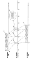
図10は非特許文献1の「CAN入門」に示されている従来の一般的な中継接続ユニット90の構成を概略的に示す図である。すなわち、中継接続ユニット90は、ワイヤハーネスからなる通信線91A,91Bにそれぞれ接続された車載LAN通信手段からなるポート92A,92Bと、該ポート92A,92Bに接続されたCPU(演算処理部)93と、少なくとも中継するべきメッセージの識別情報と中継先ポートの関係を示す中継情報を記録してなるメモリ94とを備えている。
FIG. 10 is a diagram schematically showing a configuration of a conventional general
CPU93はポート92A,92Bを介して受信したメッセージを全て受け取った後に、このメッセージに付された識別情報を前記メモリ94に記録された前記中継情報に含まれる識別情報と順次比較し、他のポート92B,92Aに中継送信するべきメッセージであるかどうかを判別する。そして、CPU93は当該メッセージを中継送信するべきであると判別した場合には、このメッセージをポート92B,92Aに中継送信することが行われている。
After receiving all the messages received via the
また、近年はより高速に通信可能であるFlexRay(登録商標)規格に準拠する車載LANを幹線として用いることが考えられっている。例えば、通信線91Aを幹線とする場合には、通信線91Bを支線として複数のECU95A,95B…をCAN規格に準拠する通信線91Bにまとめて接続し、これらを前記中継接続ユニット90によって幹線91Aに接続するように構成する。このようなECU95A,95B…のグループはそれぞれ中継接続ユニット90を介して幹線91Aに接続されることにより、この幹線91Aに接続された別の中継接続ユニット90’および通信線91Cを介して別のグループのECU95C,95D…とメッセージの送受信を行うことが可能となる。
In recent years, it is considered to use an in-vehicle LAN conforming to the FlexRay (registered trademark) standard, which can communicate at higher speed, as a trunk line. For example, when the
ところが、中継接続ユニット90を用いて通信方式の異なる車載LAN間で中継する場合は各通信線91A,91Bの通信方式が異なることによって独特の問題が発生する。例えば、FlexRayの場合、通信線91Aにメッセージを送信するための送信権が周期的に割り当てられることにより、より確実な通信を行えるように構成されているので、中継接続ユニット90が送信権を待つ時間があることにより、遅れが生じるという問題がある。
However, when relaying between in-vehicle LANs having different communication methods using the
図11は前記問題点をタイムチャートにして説明する図である。時点Tpsにおいて一方の通信線91Bに接続された1つのECU95Aからのメッセージの送信が開始すると、中継接続ユニット90がこのメッセージを受信完了する時点Tpeは、通信線91Aの送信権が与えられる時点Tp3を過ぎた時点であるから、このメッセージを通信線91Aに中継するのは次の送信権が与えられる時点Tp4である。したがって、メッセージが別の通信線91Cに中継開始される時点TprはECU95Aが送信開始した時点Tpsからかなり(図11では3周期以上)遅れた時点になってしまうことがあった。
FIG. 11 is a diagram for explaining the above-mentioned problem using a time chart. When transmission of a message from one
非特許文献1に示される中継接続ユニット90のように、メッセージの中継に関する前記一連の処理をCPU93がソフトウエアによって実行する場合には、CPU93に高い処理能力が求められるという問題が生じる。つまり、CPU93によって扱われる中継する必要があるかどうかの判別を行うメッセージ量が増大すればするほど、メッセージが受信ノードに到着するまでの時間が遅延するという問題が生じる。とりわけ、近年においては車載LANがさらに複雑になる傾向があるため、3以上の数の通信線を中継する中継接続ユニットが必要となってきており、前記CPU93に取り込まれるメッセージ数が多くなることは避けられないので、それだけ中継にかかる遅延時間が長くなるという問題が生じる。
As in the
本発明は上述の問題を考慮に入れてなされたものであり、異なる車載LAN間においてメッセージの中継を可能な限り高速に行うことができる中継接続ユニットを提供することを課題としている。 The present invention has been made in consideration of the above-described problems, and an object thereof is to provide a relay connection unit capable of relaying messages between different in-vehicle LANs as fast as possible.
前記課題を解決するため、本発明は、
FlexRay規格に準拠する第1通信線と接続した第1ポートと、
CAN規格に準拠すると共に通信速度が前記第1通信線より低速である第2通信線と接続した第2ポートと、
前記第1ポートと第2ポートとに接続する中継処理手段を備え、
前記中継処理手段は、前記第1ポートに接続する第1受信部および第1送信部と、前記第2ポートに接続する第2受信部と第2送信部と、前記第1受信部と第2送信部との間に介設した第1バッファと、前記第2受信部と第1送信部との間に介設した第2バッファを備え、
前記第1ポートで受信メッセージを受信できた部分から前記第1バッファで順次記憶すると共に該第1バッファに受信メッセージが少なくとも一部が記憶された時に該記憶されたメッセージを前記第2ポートから送信できると共に、
前記第2ポートで受信メッセージを所定の長さを受信する毎に前記第2バッファで順次記憶し、該第2バッファに記憶した部分からメッセージを前記第1ポートから送信できる構成としていることを特徴とする中継接続ユニット
を提供している。
In order to solve the above problems, the present invention provides:
A first port connected to a first communication line conforming to the FlexRay standard ;
A second port connected to a second communication line conforming to the CAN standard and having a communication speed lower than that of the first communication line ;
Relay processing means for connecting to the first port and the second port;
The relay processing means includes a first receiver and a first transmitter connected to the first port, a second receiver and a second transmitter connected to the second port, the first receiver and the second A first buffer interposed between the transmitter and a second buffer interposed between the second receiver and the first transmitter;
The received message is sequentially stored in the first buffer from the part where the received message can be received at the first port, and the stored message is transmitted from the second port when at least a part of the received message is stored in the first buffer. As well as
The received message is sequentially stored in the second buffer every time a predetermined length is received at the second port, and the message can be transmitted from the first port from the portion stored in the second buffer. The relay connection unit is provided.
前記構成よりなる中継接続ユニットによれば、第2ポートを介してメッセージを受信するときに、バッファはこの受信メッセージをその受信した部分から順次記憶する。そして、中継処理手段がバッファに記憶する受信メッセージを、バッファに記憶した部分から第1ポートを介して送信する。したがって、第2ポートから受信する受信メッセージが最後まで受信完了していなくても、第1通信線の送信権が割り当てられた時点においてバッファに記憶している部分までの受信メッセージ(少なくとも一部)を第1通信線に送信することができる。したがって、第1ポートの通信方式のように送信権が割り当てられるまでメッセージの送信を待つ必要がある車載LANにメッセージを送信する場合にも、可能な限り高速にメッセージを中継することができる。つまり、メッセージの中継にかかる遅延時間を可及的に短くすることができる。 According to the relay connection unit configured as described above, when receiving a message via the second port, the buffer sequentially stores the received message from the received portion. Then, the reception message stored in the buffer by the relay processing means is transmitted from the portion stored in the buffer via the first port. Therefore, even if the reception message received from the second port is not completely received, the reception message (at least part) up to the portion stored in the buffer at the time when the transmission right of the first communication line is assigned. Can be transmitted to the first communication line. Therefore, even when a message is transmitted to an in-vehicle LAN that needs to wait for transmission of a message until a transmission right is assigned as in the first port communication method, the message can be relayed as fast as possible. That is, the delay time required for message relay can be shortened as much as possible.
削除 Delete
前記のように、バッファが前記第1ポートを介して受信するメッセージを記憶する第1バッファと、前記第2ポートを介して受信するメッセージを記憶する第2バッファとからなり、
前記第1通信線の通信速度が第2通信線の通信速度より高速であり、かつ、
前記中継処理手段は、
前記第1ポートを介して受信する受信メッセージを受信した部分から順次前記第1バッファに記憶する第1受信部と、
前記第2バッファにメッセージの少なくとも一部が記憶されており、かつ、前記第1通信線の送信権が割り当てられたときにこの記憶されているメッセージの少なくとも一部を前記第1ポートを介して送信する第1送信部と、
前記第2ポートを介して受信するメッセージの所定の長さを受信する毎に前記第2バッファに記憶する第2受信部と、
前記第1バッファにメッセージの少なくとも一部が記憶されたときにこの記憶されたメッセージを第2ポートを介して送信する第2送信部とを備えている。
As described above, the buffer includes a first buffer for storing a message received via the first port, and a second buffer for storing a message received via the second port;
The communication speed of the first communication line is higher than the communication speed of the second communication line, and
The relay processing means includes
A first receiving unit for sequentially storing the received message received via the first port in the first buffer from the received part;
At least a part of the message is stored in the second buffer, and when the transmission right of the first communication line is assigned, at least a part of the stored message is passed through the first port. A first transmitter for transmitting;
A second receiving unit for storing in the second buffer each time a predetermined length of a message received via the second port is received;
A second transmission unit configured to transmit the stored message via the second port when at least a part of the message is stored in the first buffer .
上記構成によれば、第1受信部は第1ポートを介してメッセージを受信するときに受信メッセージの受信した部分から順次第1バッファに記憶するので、第2送信部は第1バッファに受信メッセージの少なくとも一部が記憶されているときに第2ポートを介して該メッセージの送信を開始するための送信要求を発生する。ここで、第1通信線の通信速度が第2通信線の通信速度より高速であるから、中継処理手段が第2ポートを介してメッセージを送信するときに、送信するべきメッセージがバッファ内に記憶されていないという事態が発生することはない。 According to the above configuration, when the first receiving unit receives a message via the first port, it stores the received message in the first buffer sequentially from the received part of the received message, so the second transmitting unit stores the received message in the first buffer. When at least a part of the message is stored, a transmission request for starting transmission of the message is generated via the second port. Here, since the communication speed of the first communication line is higher than the communication speed of the second communication line, when the relay processing means transmits a message via the second port, the message to be transmitted is stored in the buffer. The situation that is not done does not occur.
他方、前記第2受信部は第2ポートを介してメッセージを受信するときに、受信メッセージの所定長さを受信する毎に第2バッファに記憶するので、第1送信部は第2バッファに受信メッセージの少なくとも一部が記憶されており、かつ、第1通信線の送信権が割り当てられたときに第2バッファに記憶されているメッセージを第1ポートを介して送信する。ここで、第2バッファには所定の長さ単位で受信メッセージが記憶されるので、この所定の長さを第1ポートを介して送信できる最短メッセージ長に設定することにより、第1通信線の使用効率を良くすることができる。 On the other hand, when the second receiving unit receives a message through the second port, the second transmitting unit stores the predetermined length of the received message in the second buffer every time it receives the message. When at least part of the message is stored and the transmission right of the first communication line is assigned, the message stored in the second buffer is transmitted via the first port. Here, since the received message is stored in the second buffer in a predetermined length unit, the predetermined length is set to the shortest message length that can be transmitted through the first port, so that the first communication line Use efficiency can be improved.
なお、第1通信線の通信速度が第2通信線の通信速度より高速であるから、第2ポートを介して受信するメッセージは複数のメッセージに分けられると共に、第1通信線の送信権が割り当てられる複数のタイミングにおいて送信される。したがって、この第1通信線に接続される別の中継接続ユニットでは、これらのメッセージを受信するときに、これらをまとめて1つのメッセージとして第2通信線に中継することができる。 Since the communication speed of the first communication line is higher than the communication speed of the second communication line, the message received via the second port is divided into a plurality of messages and the transmission right of the first communication line is assigned. Transmitted at a plurality of timings. Therefore, in another relay connection unit connected to the first communication line, when these messages are received, they can be collectively relayed to the second communication line as one message.
なお、前記バッファは第1ポートを介して受信するメッセージを記憶する第1バッファと第2ポートを介して受信するメッセージを記憶する第2バッファに分けているので、バッファにメッセージを記憶する処理の流れが煩雑になることはない。しかしながら第1バッファと第2バッファは1つのバッファ内の領域を分けて形成してもよい。また、第1バッファと第2バッファの領域分けは動的に変更されるものであってもよい。さらに、前記第1,2受信部および第1,2送信部は何れも中継処理手段によって実行されるソフトウェアであってもよい。 The buffer is divided into a first buffer for storing messages received via the first port and a second buffer for storing messages received via the second port. The flow is not complicated. However, the first buffer and the second buffer may be formed by dividing the area in one buffer. Further, the area division of the first buffer and the second buffer may be dynamically changed. Further, the first and second receivers and the first and second transmitters may be software executed by the relay processing means.
複数の前記第2通信線にそれぞれ接続された複数の前記第2ポートを備え、これら複数の第2ポートを前記中継処理手段に接続し、これら複数の第2通信線間で相互にメッセージを送受信できる構成としてもよい。
また、前記中継処理手段は、前記受信メッセージの識別情報とその中継先となる第1ポートあるいは/および第2ポートとの関係を示す中継情報記憶手段を備え、受信メッセージを前記識別情報毎にバッファに記憶すると共に、前記中継情報記憶手段に記憶された識別情報と受信メッセージの識別情報を比較することにより、中継の要否および中継先を判別して前記中継処理を行うものであることが好ましい。
A plurality of second ports connected to the plurality of second communication lines, respectively, the plurality of second ports connected to the relay processing means, and messages transmitted and received between the plurality of second communication lines; It is good also as a structure which can be performed.
The front SL relay processing means includes a relay information storage means for indicating the relationship between the first port or / and the second port comprising identification information of the received message and its relay destination, the received message for each of said identification information The relay process is performed by determining the necessity of relay and the relay destination by comparing the identification information stored in the buffer and the identification information stored in the relay information storage unit with the identification information of the received message. preferable.
前記構成の中継接続ユニットによれば、第1通信線と複数の第2通信線の間または複数の第2通信線間でメッセージの送受信を行う。また、バッファには受信メッセージと識別情報が記憶されているので、3以上の数のポートがあったとしても、メッセージの識別情報を中継情報記憶手段に記憶されている識別情報と比較することにより中継の要否および中継先を適切に判別して、必要な場合は中継送信することができる。 According to the relay connection unit configured as described above, messages are transmitted and received between the first communication line and the plurality of second communication lines or between the plurality of second communication lines. Since the received message and identification information are stored in the buffer, even if there are three or more ports, the message identification information is compared with the identification information stored in the relay information storage means. The necessity of relay and the relay destination can be appropriately determined, and relay transmission can be performed if necessary.
さらに、複数の第2ポートからそれぞれ受信する複数のメッセージを同時に第1ポートに中継送信する場合にも、識別情報と受信完了した部分までの受信メッセージをまとめて第1ポートに送信することも可能であり、これによってさらに効率的なメッセージの中継を行うことができる。 Furthermore, even when a plurality of messages respectively received from a plurality of second ports are relayed and transmitted to the first port at the same time, it is also possible to send the identification information and the received messages up to the portion where reception has been completed to the first port. Thus, more efficient message relaying can be performed.
前記バッファが各受信メッセージの中継先をそれぞれ記憶するものであり、
前記中継処理手段は、前記バッファに記憶する各受信メッセージの識別情報を用いて前記中継情報記憶手段に記憶する中継先となる第1ポートあるいは/および第2ポートの情報を前記中継先としてバッファに記憶する中継判別部を有することが好ましい。
The buffer stores a relay destination of each received message;
The relay processing means uses the identification information of each received message stored in the buffer as a relay destination to store information on the first port and / or the second port as a relay destination stored in the relay information storage means. It is preferable to have a relay discrimination unit for storing.
前記構成の中継接続ユニットによれば、中継判別部がバッファに記憶されている各受信メッセージの識別情報を用いて前記中継情報記憶手段に記憶する中継先となる第1ポートあるいは/および第2ポートの情報を前記中継先としてバッファに記憶するので、各ポートからメッセージを受信するときに、各メッセージの識別情報を受信した段階で、このメッセージを中継する必要があるかどうか、および、どの中継先ポートに中継送信する必要があるかを速やかに判断することができる。つまり、中継接続ユニットのハードウェア化によって、中継速度の高速化を図ることができる。 According to the relay connection unit having the above configuration, the first port and / or the second port serving as a relay destination stored in the relay information storage unit by using the identification information of each received message stored in the buffer by the relay determination unit Is stored in the buffer as the relay destination, and when receiving a message from each port, whether or not the message needs to be relayed when receiving the identification information of each message, and which relay destination It is possible to quickly determine whether relay transmission to a port is necessary. That is, the relay speed can be increased by implementing the relay connection unit in hardware.
また、前記中継処理手段における中継先の判別を中継判別部によってハードウェア化することが可能となる。すなわち、中継処理手段内の各部動作を分散させて並列的に行うことができるので、中継速度の低下が問題になることを防止できる。 In addition, the relay determination unit in the relay processing unit can be hardwareized by the relay determination unit. That is, since the operations of each part in the relay processing means can be distributed and performed in parallel, it is possible to prevent a decrease in the relay speed from becoming a problem.
本発明の中継接続ユニットは、異なる通信方式の車載LAN間でメッセージの中継を行う場合において、最後まで受信できていない受信メッセージを、一部であっても受信した部分まで中継送信することが可能であるから、メッセージの中継に必要な時間を可及的に短くすることができる。 The relay connection unit of the present invention can relay and transmit a received message that has not been received to the end, even if it is a part, when relaying messages between in-vehicle LANs of different communication methods Therefore, the time required for message relay can be shortened as much as possible.
以下、本発明の中継接続ユニット1の実施形態について図面を参照して説明する。
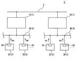
図1〜図8は本発明の第1実施形態を説明する図であり、図1は第1実施形態に係る中継接続ユニット1(図1には、各中継接続ユニット1を符号1A、1B…によって表し、以下の説明において特に区別が必要なときは中継接続ユニット1A,1B…という)を用いて形成する車載LANシステムLの構成を示し、図2は中継接続ユニット1の内部を概念的に示すブロック図、図3はバッファの一例を説明する図、図4〜図7は各部の詳細な動作を説明する図、図8は中継接続ユニット1を用いたメッセージmの中継を行う例を示す図である。
Hereinafter, embodiments of the
1 to 8 are diagrams for explaining a first embodiment of the present invention. FIG. 1 shows a
図1に示す車載LANシステムLにおいて、2は中継接続ユニット1に接続されたECU(以下、各ECU2を区別して説明するときは符号2A,2B…、2C,2D…を用いる)、3は中継接続ユニット1A,1B…を接続する第1通信線(本実施形態ではFlexRayの規格に準拠する通信線)、4は各ECU2…を中継接続ユニット1に接続する第2通信線(本実施例ではCANの規格に準拠する通信線であり、以下、各第2通信線4を区別して説明するときは符号4A,4B…)である。
In the in-vehicle LAN system L shown in FIG. 1,
図2に示すように、前記中継接続ユニット1は、前記第1通信線3にメッセージm(図1には各メッセージma,mb…を図示している)を送信するように構成されたFlexRay通信手段からなる第1ポート10と、前記第2通信線4にメッセージmを送信するCAN通信手段からなる第2ポート11と、各ポート10,11に接続されて該ポート10,11を介して受信するメッセージmを受信できた部分から該ポート11,10を介して中継送信する中継処理手段12とを有する。
As shown in FIG. 2, the
また、前記中継処理手段12は、前記第1ポート10または第2ポート11を介して受信するメッセージmを受信できた部分から順次記憶する第1バッファ13aと第2バッファ13b(以下、これらのバッファ13a,13bを区別しない場合には単にバッファ13という)とを備える。
Further, the relay processing means 12 includes a
図3は前記第1バッファ13a、第2バッファ13bの構成を説明する図である。図3に示すようにバッファ13は大きく第1バッファ13aの領域Aと第2バッファ13bの領域Bに分けられており、各メッセージm毎に識別情報ID、メッセージ長LEN、記憶メッセージ長MLENおよびデータDを関連づけて記憶するものである。また、データDの部分は例えばFIFO方式で読み書き可能に構成されている。
FIG. 3 is a diagram illustrating the configuration of the
また、前記中継処理手段12は、第1ポート10を介して受信するメッセージmの受信できた部分を逐一前記第1バッファ13aに記憶する第1受信部15と、前記第2バッファ13bにメッセージmの少なくとも一部が記憶されており、かつ、前記第1通信線の送信権が割り当てられたときにこの記憶されているメッセージmを前記第1ポート10を介して送信する第1送信部16と、前記第2ポート11を介して受信するメッセージmの所定の長さを受信する毎に前記第2バッファ13bに記憶する第2受信部17と、前記第1バッファ13aにメッセージmの少なくとも一部が記憶されたときにこの記憶されたメッセージmを第2ポート11を介して送信する第2送信部18と、各受信メッセージmの識別情報IDと中継の要否の関係を示す中継情報記憶手段19とを備える。
In addition, the relay processing means 12 stores the received part of the message m received via the
さらに、19a,19bは前記第1受信部15,第2受信部17によって受信する各受信メッセージma,mb…の識別情報IDを用いて前記中継情報記憶手段19に記憶する中継先となる第1ポート10あるいは第2ポート11の情報を参照し、各メッセージma,mb…の中継の要否を判別してバッファ13a,13bに記憶する中継判別部である。なお、本実施形態の場合は、中継接続ユニット1に第1ポート10および第2ポート11がそれぞれ1つずつ形成される例を示しているので、中継判別部19a,19bによる判別は中継の要否のみでよいが、中継接続ユニット1が複数の第2ポート11を有する場合には、前記中継情報記憶手段19が中継先のポート情報を記憶し、前記中継判別部19a,19bは識別情報ID(後述する)を用いて中継先のポート情報を判別するものであることが好ましい。
Further, 19a and 19b are first relay destinations to be stored in the relay information storage means 19 using the identification information ID of each received message ma, mb... Received by the
他方、前記ECU2…は例えばCANの規格に準拠するメッセージma,mb…,mc,md…の入出力手段20を備えており、前記第1通信線3はFlexRayなどの時分割通信を行う車載LANの規格に準拠するツイストペアケーブルであり、前記通信線4はCANなどのCSMA/CA方式の通信を行う車載LANの規格に準拠するツイストペアケーブルである。
On the other hand, the
第1通信線3は5Mbps、第2通信線4は500kpsの通信速度でメッセージmを送受信するものである。つまり、本実施形態において第1通信線3は第2通信線4に比べて通信速度が十分に高速であり、この通信線4を幹線として車載LANシステムLを構成する各中継接続ユニット1A,1B…を接続することにより、各中継接続ユニット1にCANによって接続される各ECU2A,2B…,2c,2d…が互いにメッセージmを送受信できるように構成している。また、第1通信線3が第2通信線4に比べて十分に高速であるから、中継接続ユニット1A,1B…と第1通信線3を用いたメッセージmの中継を行っても第1通信線3の通信負荷率に余裕を持たせることができる。
The
削除 Delete
図4は前記第1受信部(以下、FlexRay受信部という)15の動作を説明する図である。図4に示す処理は、FlexRayのサイクルにおいて、中継接続ユニット1内の第1ポート10を介して中継するべきメッセージmの各部分の情報(以下、受信データという)を受信する毎に実行される。なお、中継するべきメッセージmであるかどうかの判別は第1ポート10を介して受信する識別情報IDを用いて前記中継判別部19bによって行われる。
FIG. 4 is a diagram for explaining the operation of the first receiver 15 (hereinafter referred to as “FlexRay receiver”). The process shown in FIG. 4 is executed every time information (hereinafter referred to as reception data) of the message m to be relayed via the
Sa1は受信データDを第1バッファ13aに記憶するステップである。ここで、各メッセージmを構成する受信データDをメッセージmの識別情報ID毎に異なる領域に順次記憶する。また、図3に示す例では第1バッファ13aに記憶される受信データDはビット単位であるが、この受信データDを所定の長さ(例えば8ビット)単位で記憶してもよい。
Sa1 is a step of storing the received data D in the
Sa2は第1バッファ13aに記憶した受信データDが最後のデータであるかどうかを判断するステップである。つまり、最後のデータであった場合には、次のステップSa3の処理を行い、最後のデータでなかった場合には、そのまま終了する。
Sa2 is a step of determining whether or not the received data D stored in the
Sa3は前記ステップSa2において最後のデータであると判断したときに実行され、データ終了処理を実行するステップである。このステップSa3の処理において、受信データの正確性を例えばメッセージmの最後に付けられるCRCデータを用いてチェックすることができる。 Sa3 is executed when it is determined in step Sa2 that it is the last data, and is a step for executing a data end process. In the process of step Sa3, the accuracy of the received data can be checked using, for example, CRC data attached to the end of the message m.
前記ステップSa1〜Sa3の処理は第1ポート10を介して受信データの受信処理が行われている間実行され続けるものである。
The processes of steps Sa1 to Sa3 are continuously executed while the reception process of the reception data is being performed via the
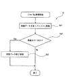
図5は前記第1送信部(以下、FlexRay送信部という)16の動作を説明する図である。図5に示す処理は、FlexRayのサイクルにおいて、中継接続ユニット1に第1通信線3を用いてメッセージmを送信する送信権(以下、タイムスロットという)が与えられるときに実行される。
FIG. 5 is a diagram for explaining the operation of the first transmitter 16 (hereinafter referred to as “FlexRay transmitter”). The processing shown in FIG. 5 is executed when a transmission right (hereinafter referred to as a time slot) for transmitting the message m using the
Sb1は第2バッファ13bに送信対象となるメッセージmの少なくとも一部の情報(以下、送信データという)が記憶されているかどうかを判断するステップである。そして、送信データDがあると判断したときには続くステップSb2の処理を実行し、送信データDが無いと判断したときには今回のタイムスロットでは何もしないで終了する。
Sb1 is a step of determining whether or not at least a part of information (hereinafter referred to as transmission data) of the message m to be transmitted is stored in the
Sb2は第2バッファ13bに記憶されている送信データDを送信するステップである。このとき、第2バッファ13bには、送信データDとして各メッセージma,mb…を構成する各部分の情報がその識別情報IDと共に記憶されているので、送信データDとして元のメッセージma,mb…を構成する各部分の情報と識別情報IDを送信する。
Sb2 is a step of transmitting the transmission data D stored in the
Sb3は第2バッファ13b中の送信済データDの削除処理を行うステップである。
Sb3 is a step for performing a process of deleting the transmitted data D in the
図6は前記第2受信部(以下、CAN受信部という)17の動作を説明する図である。図6に示す処理は、中継接続ユニット1内の第2ポート11によってメッセージmを受信するときに実行される。
FIG. 6 is a diagram for explaining the operation of the second receiver 17 (hereinafter referred to as CAN receiver). The process shown in FIG. 6 is executed when the message m is received by the
Sc1はCANに準拠する通信プロトコルによってメッセージmを構成するデータDを受信するステップである。なお、この受信ステップSc1の処理において受信中のメッセージmについて、前記中継判別部19bによって中継不要であると判別された場合には、以下のステップSc2…の実行を行うことなく、処理を終了する。
Sc1 is a step of receiving data D constituting message m by a communication protocol compliant with CAN. If it is determined by the
Sc2はステップSc1において受信しているメッセージmが所定の長さ(本実施形態の場合は8ビット)を受信したかどうか判断するステップである。ここで、受信ビット数が8ビット未満であるときには前記ステップSc1に戻って実行し、8ビットを受信すると、次のステップSc3を実行する。 Sc2 is a step of determining whether or not the message m received in step Sc1 has received a predetermined length (8 bits in this embodiment). Here, when the number of received bits is less than 8 bits, the process returns to step Sc1 and is executed, and when 8 bits are received, the next step Sc3 is executed.
Sc3は前記メッセージmの受信できた部分までの情報(受信データ)を第2バッファ13bに記憶するステップである。なお、各メッセージmを構成する受信データDをメッセージmの識別情報ID毎に異なる領域に順次記憶する。
Sc3 is a step of storing in the
Sc4は第2バッファ13bに記憶した受信データが最後のデータであり、第2通信線4から受信するべき全データを受信完了したかどうかを判断するステップである。つまり、全データを受信したと判断した場合には、次のステップSc5の処理を行い、続く受信データを受信する必要がある場合には、再びステップSc1に戻って受信処理を続行する。
Sc4 is a step of determining whether or not the received data stored in the
Sc5は前記ステップSc4において全データを受信したと判断したときに実行され、データ終了処理を実行するステップである。このステップSc4の処理において、受信データDの正確性を例えばメッセージmの最後に付けられるCRCデータを用いてチェックすることができる。 Sc5 is a step that is executed when it is determined in step Sc4 that all data has been received, and a data end process is executed. In the process of step Sc4, the accuracy of the received data D can be checked using, for example, CRC data attached to the end of the message m.
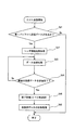
図7は前記第1送信部(以下、CAN送信部という)18の動作を説明する図である。図7に示す処理は、前記FlexRay受信部16がメッセージmの受信動作を始めるときに実行される。
FIG. 7 is a diagram for explaining the operation of the first transmitter 18 (hereinafter referred to as CAN transmitter). The processing shown in FIG. 7 is executed when the
Sd1は第1バッファ13aに送信対象となるメッセージmの少なくとも一部の情報(以下、送信データDという)が記憶されているかどうかを判断するステップである。そして、送信データDがあると判断したときには続くステップSd2の処理を実行し、送信データが無いと判断したときには何もしないで終了する。ここで、第1バッファ13aに複数の識別情報IDに対応する送信データがある場合には、そのうちの1つの識別情報IDに対応する送信データDについて、以下のステップSd2〜Dd5の処理を繰り返す。なお、ステップSd1において送信データDが無いと判断したときにもう一度ステップSd1に戻って送信データを待ち受けるようにしてもよい。
Sd1 is a step of determining whether or not at least part of information (hereinafter referred to as transmission data D) of the message m to be transmitted is stored in the
Sd2は第2通信線4を介してメッセージmを送信開始するためのヘッダ情報を送信するステップである。なお、前記ヘッダ情報にはCAN規格に準拠するアービトレーションフィールドやコントロールフィールドが含まれており、これらは前記第1バッファ13aに記憶された情報である。
Sd2 is a step of transmitting header information for starting transmission of the message m via the
Sd3は第1バッファ13aに記憶された送信データを前記第2通信線4を介して送信する処理を実行するステップである。
Sd3 is a step of executing a process of transmitting the transmission data stored in the
Sd4はステップSd3において送信した送信データDがメッセージmを構成する最後の送信データDを送信完了したかどうかを判断するステップである。ここで最後の送信データDを送信完了したと判断した場合には次のステップSd5を実行し、続く送信データDがあると判断した場合には前記ステップSd3に戻って送信処理を繰り返す。 Sd4 is a step of determining whether or not the transmission data D transmitted in step Sd3 has completed transmission of the last transmission data D constituting the message m. If it is determined that transmission of the last transmission data D is completed, the next step Sd5 is executed. If it is determined that there is subsequent transmission data D, the process returns to step Sd3 and repeats the transmission process.
なお、第1バッファ13aには、前記FlexRay受信部15の動作によって受信した受信データDが順次記憶されており、かつ、第1通信線3の通信速度は第2通信線4の通信速度より高速である。したがって、正常な通信が行われている場合には、1つのメッセージmを構成する送信データの送信を開始してから送信完了するまでの間に第1バッファ13aに送信データDが無くなるという事態が発生することはない。
The
Sd5は終了処理を実行するステップである。つまり、前記メッセージmの正確性を確認するためのCRCデータなどの冗長項を追加送信するステップである。すなわち、これによって第2通信線4を介するメッセージmの送信を完了する。
Sd5 is a step for executing an end process. That is, it is a step of additionally transmitting a redundant term such as CRC data for confirming the accuracy of the message m. That is, this completes the transmission of the message m via the
Sd6は送信完了したメッセージmに関係する送信済データを第1バッファ13aから削除して、第1バッファ13aの該当する領域を解放するステップである。
Sd6 is a step of deleting the transmitted data relating to the message m that has been transmitted from the
図8は図1に図示しているように、前記中継接続ユニット1A,1BをFlexRayの幹線(第1通信線3)に接続し、これらの中継接続ユニット1A,1Bを用いてメッセージmを中継することにより、2本の第2通信線4A,4Bに接続する各ECU2A,2B…,2C,2D…の間でメッセージmを送受信する例を説明する。
As shown in FIG. 1, FIG. 8 connects the
図8に示すように時点Tsにおいて、第2通信線4Aに接続された1つのECU2がメッセージmを送信すると、このメッセージmが中継接続ユニット1A内の前記CAN受信部17が受信し、8ビット単位で区切った受信データD1を第2バッファ13bに記憶する。
As shown in FIG. 8, at time Ts, when one
なお、CANのメッセージmは例えばプリアンブルに続いてメッセージmのアービトレーションフィールドを形成する識別情報IDやコントロールフィールドを形成するメッセージ長LENなどの情報が含まれたヘッダ情報から始まっている。したがって、前記中継判別部19bは識別情報IDを受信した段階でこのメッセージmを中継する必要があるかどうか判断し、中継する必要があると判別できたときに、これらの情報ID,LENを第2バッファ13b内に記憶して、一連のデータD1,D2…の中継を行う。
The CAN message m starts with header information including information such as an identification information ID that forms an arbitration field of the message m and a message length LEN that forms a control field following the preamble, for example. Therefore, the
図示する例では、第1通信線3の送信権が中継接続ユニット1Aに与えられるタイムスロットが開始する時点T2において受信データD1のみを受信完了して第2バッファ13bに記憶しているので、時点T2から始まるタイムスロットにおいては、FlexRay送信部16が第2バッファ13bに記憶された送信データD1をメッセージm1として第1通信線3に送信する。
In the example shown in the figure, since reception of only the received data D1 is completed and stored in the
一方、第1通信線3に接続された中継接続ユニット1Bは前記データD1を受信すると、前記中継判別部19aがこの識別情報IDによって中継する必要があるかどうかを判別する。そして、中継する必要があると判別した場合には、FlexRay受信部15が最初のデータD1の受信を開始し、第1バッファ13aにデータを記憶する。前記CAN送信部18は第1バッファ13aに記憶された送信データD1を時点Ts’においてすぐに第2通信線4Bに送信する。
On the other hand, when the
同様に、中継接続ユニット1Aは、続くデータD2〜D6を第1通信線3の送信権が次に中継接続ユニット1Aに与えられるタイムスロットが開始する時点T3においてまとめてメッセージm2として中継送信し、中継接続ユニット1Bはこのメッセージm1を受信すると、これらのデータD2〜D6を第2通信線4Bに中継する。さらに、データD7,D8は時点T4にメッセージm3としてまとめられて中継送信される。なお、前記メッセージmを分割して生成されるメッセージm1〜m3は何れもメッセージmの一部分であることが分かるように識別情報IDを含んでいる。(図7にはメッセージm3の構成のみ拡大図にして示している)
Similarly, the
また、図8に示すように、第1通信線3の通信速度が、第2通信線4A,4Bの通信速度よりも高速であるから、中継接続ユニット1BのCAN送信部18がCANのメッセージmを中継送信するとき、CAN送信部18が次の送信データD2〜D6、D7,D8を必要とする時には、これらの送信データD2〜D6、D7,D8が第1バッファ13aに記憶されている。したがって、複数に分けられたメッセージm1〜m3を再び1つのメッセージmにまとめて、CAN送信部18によって送信するときにも、必要な送信データが第1バッファ13aにないという事態が発生することはない。
Further, as shown in FIG. 8, since the communication speed of the
以上、詳述したように、本発明の中継接続ユニット1を用いることにより、異なる通信方式を採用する車載LANの間でメッセージmの中継を行う場合にも、中継接続ユニット1Bがメッセージmの中継送信を送信元のECU2からメッセージmを送信完了する時点Teよりも前の時点Ts’から中継送信を開始することが可能である。とりわけ、第1通信線にメッセージmを送信するための送信権が周期的に割り当てられるような車載LANを介在させてメッセージmを中継する場合にも可及的に高速に中継を行うことが可能である。
As described above, by using the
なお、前記第1通信線3の送信権を割り当てられるタイムスロットの開始時点T1,T2…の間隔は短ければ短いほど中継送信の遅れ時間を短くすることができるので有用である。また、より確実な中継を行うことを可能とするためには前記送信権を割り当てられるタイムスロットとしてFlexRayの静的セグメントを用いることが好ましいが、前記タイムスロットとして優先順位を高く設定して動的セグメントを用いてもよい。
It is useful that the shorter the interval between the start times T1, T2,... Of the time slot to which the transmission right of the
図9は第2実施形態に係る中継接続ユニット30の構成を説明する図である。本実施形態において図1〜8に示す第1実施形態と異なる点は、複数の第2通信線4C〜4Fにそれぞれ接続されてそれぞれECU2E〜2Hとの間でメッセージme,mf…の送受信を行う第2ポート11a〜11dを設けた点である。また、前記中継処理手段12内の中継情報記憶手段19には各メッセージmの識別情報ID毎に中継先のポート情報(第1ポート10、第2ポート11a〜11dを識別する情報)を記憶している。
FIG. 9 is a diagram illustrating the configuration of the
本実施形態のように構成された中継接続ユニット30を用いることにより、第2通信線4C〜4Fの間で相互にメッセージmを中継して送受信することが可能であり、各第2通信線4C〜4Fを用いて送受信するメッセージmの量を削減できるので、大量のデータを送受信する場合にも衝突などの問題を起こすことがない。また、必要なときには第1通信線3を介して別の中継接続ユニット(図外)との間でメッセージmを中継して送受信することも可能であると共に、可能な限り中継の遅れ時間を短くすることができる。
By using the
1(1A,1B) 中継接続ユニット
2(2A,2B…) ECU
3 第1通信線
4 第2通信線
10 第1ポート
11 第2ポート
13 バッファ
13a 第1バッファ
13b 第2バッファ
15 第1受信部
16 第1送信部
17 第2受信部
18 第2送信部
19 中継情報記憶手段
19a,19b 中継判別部
1 (1A, 1B) Relay connection unit 2 (2A, 2B ...) ECU
3
Claims (4)
CAN規格に準拠すると共に通信速度が前記第1通信線より低速である第2通信線と接続した第2ポートと、
前記第1ポートと第2ポートとに接続する中継処理手段を備え、
前記中継処理手段は、前記第1ポートに接続する第1受信部および第1送信部と、前記第2ポートに接続する第2受信部と第2送信部と、前記第1受信部と第2送信部との間に介設した第1バッファと、前記第2受信部と第1送信部との間に介設した第2バッファを備え、
前記第1ポートで受信メッセージを受信できた部分から前記第1バッファで順次記憶すると共に該第1バッファに受信メッセージが少なくとも一部が記憶された時に該記憶されたメッセージを前記第2ポートから送信できると共に、
前記第2ポートで受信メッセージを所定の長さを受信する毎に前記第2バッファで順次記憶し、該第2バッファに記憶した部分からメッセージを前記第1ポートから送信できる構成としている中継接続ユニット。 A first port connected to a first communication line conforming to the FlexRay standard;
A second port connected to a second communication line conforming to the CAN standard and having a communication speed lower than that of the first communication line;
Relay processing means for connecting to the first port and the second port;
The relay processing means includes a first receiver and a first transmitter connected to the first port, a second receiver and a second transmitter connected to the second port, the first receiver and the second A first buffer interposed between the transmitter and a second buffer interposed between the second receiver and the first transmitter;
The received message is sequentially stored in the first buffer from the part where the received message can be received at the first port, and the stored message is transmitted from the second port when at least a part of the received message is stored in the first buffer. As well as
A relay connection unit configured to sequentially store a received message at the second port every time a predetermined length is received by the second buffer and to transmit a message from the portion stored in the second buffer from the first port. .
Priority Applications (1)
| Application Number | Priority Date | Filing Date | Title |
|---|---|---|---|
| JP2012129086A JP2012191659A (en) | 2012-06-06 | 2012-06-06 | Relay connection unit |
Applications Claiming Priority (1)
| Application Number | Priority Date | Filing Date | Title |
|---|---|---|---|
| JP2012129086A JP2012191659A (en) | 2012-06-06 | 2012-06-06 | Relay connection unit |
Related Parent Applications (1)
| Application Number | Title | Priority Date | Filing Date |
|---|---|---|---|
| JP2006193613A Division JP5278886B2 (en) | 2006-07-14 | 2006-07-14 | Relay connection unit |
Publications (1)
| Publication Number | Publication Date |
|---|---|
| JP2012191659A true JP2012191659A (en) | 2012-10-04 |
Family
ID=47084264
Family Applications (1)
| Application Number | Title | Priority Date | Filing Date |
|---|---|---|---|
| JP2012129086A Pending JP2012191659A (en) | 2012-06-06 | 2012-06-06 | Relay connection unit |
Country Status (1)
| Country | Link |
|---|---|
| JP (1) | JP2012191659A (en) |
Citations (6)
| Publication number | Priority date | Publication date | Assignee | Title |
|---|---|---|---|---|
| JPS63224443A (en) * | 1987-03-13 | 1988-09-19 | Kokusai Denshin Denwa Co Ltd <Kdd> | Semi-storing type packet switching system |
| JPS63232544A (en) * | 1987-03-19 | 1988-09-28 | Fujitsu Ltd | Multi-channel packeting system |
| JPS6422141A (en) * | 1987-07-17 | 1989-01-25 | Nippon Telegraph & Telephone | Transmission control system |
| JPH0766833A (en) * | 1993-08-24 | 1995-03-10 | Mitsubishi Electric Corp | Frame repeater, frame repeater group and relay method |
| JP2001358764A (en) * | 2000-06-13 | 2001-12-26 | Nec Corp | Circuit and method for header conversion |
| JP2005328119A (en) * | 2004-05-12 | 2005-11-24 | Nec Electronics Corp | Communication message converter, communication method, and communication system |
-
2012
- 2012-06-06 JP JP2012129086A patent/JP2012191659A/en active Pending
Patent Citations (6)
| Publication number | Priority date | Publication date | Assignee | Title |
|---|---|---|---|---|
| JPS63224443A (en) * | 1987-03-13 | 1988-09-19 | Kokusai Denshin Denwa Co Ltd <Kdd> | Semi-storing type packet switching system |
| JPS63232544A (en) * | 1987-03-19 | 1988-09-28 | Fujitsu Ltd | Multi-channel packeting system |
| JPS6422141A (en) * | 1987-07-17 | 1989-01-25 | Nippon Telegraph & Telephone | Transmission control system |
| JPH0766833A (en) * | 1993-08-24 | 1995-03-10 | Mitsubishi Electric Corp | Frame repeater, frame repeater group and relay method |
| JP2001358764A (en) * | 2000-06-13 | 2001-12-26 | Nec Corp | Circuit and method for header conversion |
| JP2005328119A (en) * | 2004-05-12 | 2005-11-24 | Nec Electronics Corp | Communication message converter, communication method, and communication system |
Similar Documents
| Publication | Publication Date | Title |
|---|---|---|
| US11463275B2 (en) | Electronic control unit, frame generating method, and non-transitory computer-readable recording medium storing a program | |
| JP2017212724A (en) | Gateway device, on-vehicle network system, transfer method, and program | |
| US20210184886A1 (en) | In-vehicle information processing for unauthorized data | |
| JP2006333438A (en) | Gateway apparatus and routing method | |
| US20160173397A1 (en) | Communication control device, method of communicating a frame, and storage medium | |
| JP5767277B2 (en) | Gateway device | |
| WO2017141676A1 (en) | Relay device | |
| JP6544230B2 (en) | Communications system | |
| JP2008227741A (en) | On-vehicle communication system | |
| JP5147533B2 (en) | Relay device and relay method | |
| JP5278886B2 (en) | Relay connection unit | |
| JP4839140B2 (en) | Relay connection unit | |
| CN102100037A (en) | Subscriber nodes of a communication system having a functionally separate transmission event memory | |
| JP2006253922A (en) | Gateway apparatus and data transfer method for the gateway apparatus | |
| JP4754940B2 (en) | Relay connection unit | |
| JP2012191659A (en) | Relay connection unit | |
| JP5050889B2 (en) | Data transmission method and data transmission apparatus | |
| US7724775B2 (en) | Data transmission circuit and method for controlling the data transmission circuit | |
| JP4917557B2 (en) | In-vehicle relay connection unit | |
| JP2014204160A (en) | Gateway unit | |
| CN108631943A (en) | Communication device, communication means and storage medium | |
| US9485139B2 (en) | Communication node, communication system, and method for performing a communication | |
| US11159456B2 (en) | Control apparatus | |
| KR100911336B1 (en) | Message Converting Apparatus Between Flexray and CAN Communication | |
| KR101217684B1 (en) | Control area network coupler and coupling method for communication in the multiple control area networks |
Legal Events
| Date | Code | Title | Description |
|---|---|---|---|
| A977 | Report on retrieval |
Free format text: JAPANESE INTERMEDIATE CODE: A971007 Effective date: 20130510 |
|
| A131 | Notification of reasons for refusal |
Free format text: JAPANESE INTERMEDIATE CODE: A131 Effective date: 20130521 |
|
| A02 | Decision of refusal |
Free format text: JAPANESE INTERMEDIATE CODE: A02 Effective date: 20131008 |