JP2012190823A - Liquid treatment apparatus, liquid treatment method and, storage medium having computer program for executing it recorded therein - Google Patents
Liquid treatment apparatus, liquid treatment method and, storage medium having computer program for executing it recorded therein Download PDFInfo
- Publication number
- JP2012190823A JP2012190823A JP2011050389A JP2011050389A JP2012190823A JP 2012190823 A JP2012190823 A JP 2012190823A JP 2011050389 A JP2011050389 A JP 2011050389A JP 2011050389 A JP2011050389 A JP 2011050389A JP 2012190823 A JP2012190823 A JP 2012190823A
- Authority
- JP
- Japan
- Prior art keywords
- liquid processing
- liquid
- common exhaust
- processed
- outside air
- Prior art date
- Legal status (The legal status is an assumption and is not a legal conclusion. Google has not performed a legal analysis and makes no representation as to the accuracy of the status listed.)
- Granted
Links
Images

Classifications
-
- B—PERFORMING OPERATIONS; TRANSPORTING
- B08—CLEANING
- B08B—CLEANING IN GENERAL; PREVENTION OF FOULING IN GENERAL
- B08B15/00—Preventing escape of dirt or fumes from the area where they are produced; Collecting or removing dirt or fumes from that area
- B08B15/002—Preventing escape of dirt or fumes from the area where they are produced; Collecting or removing dirt or fumes from that area using a central suction system, e.g. for collecting exhaust gases in workshops
-
- H—ELECTRICITY
- H10—SEMICONDUCTOR DEVICES; ELECTRIC SOLID-STATE DEVICES NOT OTHERWISE PROVIDED FOR
- H10P—GENERIC PROCESSES OR APPARATUS FOR THE MANUFACTURE OR TREATMENT OF DEVICES COVERED BY CLASS H10
- H10P50/00—Etching of wafers, substrates or parts of devices
-
- H—ELECTRICITY
- H10—SEMICONDUCTOR DEVICES; ELECTRIC SOLID-STATE DEVICES NOT OTHERWISE PROVIDED FOR
- H10P—GENERIC PROCESSES OR APPARATUS FOR THE MANUFACTURE OR TREATMENT OF DEVICES COVERED BY CLASS H10
- H10P72/00—Handling or holding of wafers, substrates or devices during manufacture or treatment thereof
- H10P72/04—Apparatus for manufacture or treatment
- H10P72/0402—Apparatus for fluid treatment
- H10P72/0406—Apparatus for fluid treatment for cleaning followed by drying, rinsing, stripping, blasting or the like
- H10P72/0411—Apparatus for fluid treatment for cleaning followed by drying, rinsing, stripping, blasting or the like for wet cleaning or washing
- H10P72/0414—Apparatus for fluid treatment for cleaning followed by drying, rinsing, stripping, blasting or the like for wet cleaning or washing using mainly spraying means, e.g. nozzles
-
- H—ELECTRICITY
- H10—SEMICONDUCTOR DEVICES; ELECTRIC SOLID-STATE DEVICES NOT OTHERWISE PROVIDED FOR
- H10P—GENERIC PROCESSES OR APPARATUS FOR THE MANUFACTURE OR TREATMENT OF DEVICES COVERED BY CLASS H10
- H10P72/00—Handling or holding of wafers, substrates or devices during manufacture or treatment thereof
- H10P72/04—Apparatus for manufacture or treatment
- H10P72/0451—Apparatus for manufacturing or treating in a plurality of work-stations
- H10P72/0452—Apparatus for manufacturing or treating in a plurality of work-stations characterised by the layout of the process chambers
- H10P72/0456—Apparatus for manufacturing or treating in a plurality of work-stations characterised by the layout of the process chambers in-line arrangement
Landscapes
- Cleaning Or Drying Semiconductors (AREA)
Abstract
【課題】処理体を液処理する液処理部内の圧力の変動を抑制することができる液処理装置を提供する。
【解決手段】本発明による液処理装置1は、被処理体Wに対して処理液を供給して被処理体Wを液処理する複数の液処理部3と、複数の液処理部3内の雰囲気を排出する共通排気路6と、液処理部3の各々と共通排気路6とを連結する個別排気路35と、個別排気路35に開閉自在に設けられた開閉機構5と、共通排気路6に外気を取り込む外気取込部65と、を備えている。共通排気路6には、外気取込部65から取り込まれる外気の流量を調整する取込量調整弁が設けられている。制御部100は、開閉機構5の各々の開閉状態に基づいて、取込量調整弁の開度を制御するようになっている。
【選択図】図3A liquid processing apparatus capable of suppressing fluctuations in pressure in a liquid processing section for liquid processing a processing body is provided.
A liquid processing apparatus 1 according to the present invention includes a plurality of liquid processing units 3 for supplying a processing liquid to a target object W to liquid-process the target object W, and a plurality of liquid processing units 3. A common exhaust passage 6 for discharging the atmosphere, an individual exhaust passage 35 connecting each of the liquid processing units 3 and the common exhaust passage 6, an opening / closing mechanism 5 provided in the individual exhaust passage 35 so as to be openable and closable, and a common exhaust passage 6 is provided with an outside air intake unit 65 for taking in outside air. The common exhaust path 6 is provided with an intake amount adjustment valve that adjusts the flow rate of the outside air taken in from the outside air intake unit 65. The control unit 100 controls the opening degree of the intake amount adjustment valve based on the open / closed state of the open / close mechanism 5.
[Selection] Figure 3
Description
本発明は、被処理体を液処理する液処理装置、液処理方法およびこの液処理方法を実行するためのコンピュータプログラムが記録された記録媒体に関する。 The present invention relates to a liquid processing apparatus, a liquid processing method, and a recording medium on which a computer program for executing the liquid processing method is recorded.
半導体デバイスなどの製造工程には、半導体ウエハ(以下単にウエハと記す)などの被処理体の表面に薬液や純水などの処理液を供給してウエハに付着したパーティクルや汚染物質を除去する液処理工程がある。こうした液処理工程を行う液処理装置の一つに、ウエハを回転させながら当該ウエハの表面に処理液を供給して液処理する液処理装置がある。この種の液処理装置では、単位時間当たりのウエハの処理枚数(スループット)を増大させるために、例えば同種の液処理を実行可能な複数(例えば4〜5台)の液処理ユニット(液処理部)を設け、共通の搬送機構を用いて各液処理ユニットにウエハを搬送し、複数の液処理ユニットにて並行してウエハの液処理を行うようになっている。 In the manufacturing process of semiconductor devices and the like, a liquid that removes particles and contaminants attached to the wafer by supplying a treatment liquid such as a chemical solution or pure water to the surface of an object to be processed such as a semiconductor wafer (hereinafter simply referred to as a wafer) There are processing steps. One liquid processing apparatus that performs such a liquid processing process is a liquid processing apparatus that supplies a processing liquid to the surface of the wafer while rotating the wafer to perform liquid processing. In this type of liquid processing apparatus, in order to increase the number of processed wafers (throughput) per unit time, for example, a plurality of (for example, 4 to 5) liquid processing units (liquid processing units) capable of executing the same type of liquid processing are used. ), The wafer is transferred to each liquid processing unit using a common transfer mechanism, and the liquid processing of the wafer is performed in parallel by a plurality of liquid processing units.
このような液処理ユニットは、例えば、ウエハを載置して回転させるスピンチャックと、スピンチャックに保持されたウエハを囲むように設けられ、ウエハの表面に供給されて飛散した処理液を回収するカップと、を備えている。処理液としては、酸性薬液やアルカリ性薬液などが用いられており、処理に応じて、薬液をウエハWに選択的に供給するように構成されている。 Such a liquid processing unit is provided, for example, so as to surround the spin chuck on which the wafer is placed and rotated, and the wafer held by the spin chuck, and collects the processing liquid that is supplied to the surface of the wafer and scattered. And a cup. As the processing liquid, an acidic chemical liquid, an alkaline chemical liquid, or the like is used, and the chemical liquid is selectively supplied to the wafer W according to the processing.
ここで、特許文献1には、複数の液処理ユニットを水平に配置すると共に、酸性薬液用の排気ラインおよびアルカリ性薬液用の排気ラインを備える液処理装置が記載されている。例えば、酸性薬液用の排気ラインにおいては、各液処理ユニットに、酸性処理時の液処理ユニット内の雰囲気を液処理ユニット毎に排出する酸排気管が接続され、各酸排気管に酸排気配管が接続されて、各液処理ユニット内の雰囲気が、各酸排気管を通って、酸排気配管によって一括して排出されるようになっている。また、各酸排気管には、対応する液処理ユニットにおける液処理の種別に応じて開閉するバルブが設けられている。さらに、各液処理ユニットには、気流導入部から清浄空気が常に導入されており、各液処理ユニット内の清浄度が保たれている。 Here, Patent Document 1 describes a liquid processing apparatus in which a plurality of liquid processing units are arranged horizontally, and includes an exhaust line for acidic chemical liquid and an exhaust line for alkaline chemical liquid. For example, in an acid chemical liquid exhaust line, each liquid treatment unit is connected to an acid exhaust pipe for discharging the atmosphere in the liquid treatment unit during the acid treatment for each liquid treatment unit, and each acid exhaust pipe is connected to an acid exhaust pipe. Are connected, and the atmosphere in each liquid treatment unit passes through each acid exhaust pipe and is collectively discharged by the acid exhaust pipe. Each acid exhaust pipe is provided with a valve that opens and closes depending on the type of liquid treatment in the corresponding liquid treatment unit. Further, clean air is always introduced from each air treatment unit to each liquid processing unit, and the cleanliness in each liquid processing unit is maintained.
しかしながら、上述した液処理装置においては、酸排気配管の排気量は一定になっている。このため、各酸排気管に設けられたバルブのうち一のバルブが閉じられた場合、他のバルブに対応する液処理ユニットの排気量が増大し、当該液処理ユニット内の圧力が変動して低下するという問題がある。この場合、当該液処理ユニット内に外部から空気が混入され、液処理ユニット内の清浄度が低下する可能性がある。 However, in the liquid processing apparatus described above, the displacement of the acid exhaust pipe is constant. For this reason, when one of the valves provided in each acid exhaust pipe is closed, the exhaust amount of the liquid processing unit corresponding to the other valve increases, and the pressure in the liquid processing unit varies. There is a problem of lowering. In this case, air may be mixed from the outside into the liquid processing unit, and the cleanliness in the liquid processing unit may be reduced.
本発明は、このような点を考慮してなされたものであり、被処理体を液処理する液処理部内の圧力の変動を抑制することができる液処理装置、液処理方法、およびこの液処理方法を実行するためのコンピュータプログラムが記録された記録媒体を提供することを目的とする。 The present invention has been made in consideration of such points, and a liquid processing apparatus, a liquid processing method, and this liquid processing capable of suppressing fluctuations in pressure in a liquid processing section that performs liquid processing on an object to be processed. It is an object of the present invention to provide a recording medium on which a computer program for executing the method is recorded.
本発明は、被処理体に対して処理液を供給して前記被処理体を液処理する複数の液処理部と、複数の前記液処理部内の雰囲気を排出する共通排気路と、前記液処理部の各々と前記共通排気路とを連結する個別排気路と、前記個別排気路に開閉自在に設けられた開閉機構と、前記共通排気路に外気を取り込む外気取込部と、前記共通排気路に設けられ、前記外気取込部から取り込まれる外気の流量を調整する取込量調整弁と、前記開閉機構の各々の開閉状態に基づいて、前記取込量調整弁の開度を制御する制御部と、を備えたことを特徴とする液処理装置を提供する。 The present invention provides a plurality of liquid processing units for supplying a processing liquid to a target object to liquid-process the target object, a common exhaust passage for discharging the atmosphere in the plurality of liquid processing parts, and the liquid processing Individual exhaust passages that connect each of the parts and the common exhaust passage, an open / close mechanism that can be freely opened and closed in the individual exhaust passage, an outside air intake portion that takes outside air into the common exhaust passage, and the common exhaust passage An intake amount adjusting valve that adjusts the flow rate of outside air taken in from the outside air intake portion, and a control that controls the opening degree of the intake amount adjusting valve based on the open / closed state of each of the open / close mechanisms And a liquid processing apparatus characterized by comprising a section.
なお、上述した液処理装置において、前記取込量調整弁は、前記共通排気路において、前記液処理部の各々からの排気の合流点より排気方向上流側に配置されている、ことが好ましい。 In the liquid processing apparatus described above, it is preferable that the intake amount adjusting valve is disposed upstream of the merging point of the exhaust from each of the liquid processing units in the exhaust direction in the common exhaust path.
また、上述した液処理装置において、前記液処理部は、前記被処理体に対して複数種別の前記処理液を選択的に供給するように構成され、前記共通排気路は、前記液処理部において前記被処理体に対して供給される前記処理液の種別毎に前記液処理部内の雰囲気を排出する複数の専用共通排気路を有し、前記個別排気路は、対応する前記液処理部と複数の前記専用共通排気路と連結するようになっており、前記開閉機構は、前記被処理体に対して供給される前記処理液の種別に対応する前記専用共通排気路に前記液処理部を切り替えて連結する流路切替機構を有し、前記専用共通排気路の各々に、外気を取り込む前記外気取込部が設けられ、前記専用共通排気路の各々に、前記外気取込部から取り込まれる外気の流量を調整する前記取込量調整弁が設けられ、前記制御部は、前記流路切替機構の各々の切替状態に基づいて、前記取込量調整弁の各々の開度を制御する、ことが好ましい。 Further, in the liquid processing apparatus described above, the liquid processing unit is configured to selectively supply a plurality of types of the processing liquid to the object to be processed, and the common exhaust path is provided in the liquid processing unit. For each type of the processing liquid supplied to the object to be processed, a plurality of dedicated common exhaust passages for discharging the atmosphere in the liquid processing section are provided, and the individual exhaust paths are connected to the corresponding liquid processing section. The open / close mechanism switches the liquid processing unit to the dedicated common exhaust path corresponding to the type of the processing liquid supplied to the object to be processed. Each of the dedicated common exhaust passages is provided with the outside air intake portion for taking in outside air, and each of the dedicated common exhaust passages is provided with the outside air taken in from the outside air intake portion. The intake volume adjustment to adjust the flow rate of The valve is provided, wherein, based on the switching state of each of the flow path switching mechanism, to control each of the opening degree of the intake amount adjustment valve, it is preferable.
また、上述した液処理装置において、前記液処理部の各々に気体を供給する単一の気体供給部を更に備えた、ことが好ましい。 Moreover, it is preferable that the liquid processing apparatus described above further includes a single gas supply unit that supplies gas to each of the liquid processing units.
また、上述した液処理装置において、各液処理部は、前記被処理体を液処理する液処理空間を形成する液処理容器と、前記液処理容器に開閉自在に設けられ、前記液処理空間を開放可能な開閉パネルと、前記開閉パネルの開閉を検出するパネル検出部と、を有し、前記制御部は、前記パネル検出部により前記開閉パネルが開いたことが検出された場合、対応する前記開閉機構を開くように制御する、ことが好ましい。 Further, in the liquid processing apparatus described above, each liquid processing unit is provided in a liquid processing container that forms a liquid processing space for liquid processing the object to be processed, and the liquid processing container is openable and closable. An openable open / close panel, and a panel detection unit that detects opening and closing of the open / close panel, and the control unit corresponds to the opening when the open / close panel is detected by the panel detection unit. It is preferable to control the opening / closing mechanism to open.
本発明は、被処理体に対して処理液を供給して前記被処理体を液処理する複数の液処理部と、複数の前記液処理部内の雰囲気を排出する共通排気路と、前記液処理部の各々と前記共通排気路とを連結する個別排気路と、前記個別排気路に設けられた開閉機構と、前記共通排気路に外気を取り込む外気取込部と、前記共通排気路に設けられ、前記外気取込部から取り込まれる外気の流量を調整する取込量調整弁と、を備えた液処理装置を用いて、前記被処理体を液処理する液処理方法において、前記液処理部に前記被処理体を搬入する工程と、前記被処理体が搬入された前記液処理部において、前記被処理体に対して処理液を供給して前記被処理体を液処理する工程と、を備え、前記被処理体を液処理する工程において、前記液処理部の雰囲気が前記個別排気路および前記共通排気路を通って排出されると共に、前記開閉機構の各々の開閉状態に基づいて、前記取込量調整弁の開度が調整されることを特徴とする液処理方法を提供する。 The present invention provides a plurality of liquid processing units for supplying a processing liquid to a target object to liquid-process the target object, a common exhaust passage for discharging the atmosphere in the plurality of liquid processing parts, and the liquid processing An individual exhaust passage that connects each of the parts and the common exhaust passage, an opening / closing mechanism provided in the individual exhaust passage, an outside air intake portion that takes outside air into the common exhaust passage, and a common exhaust passage. In a liquid processing method for liquid processing the object to be processed using a liquid processing apparatus comprising an intake amount adjustment valve for adjusting a flow rate of outside air taken in from the outside air taking-in part, A step of carrying in the object to be processed; and a step of liquid-treating the object to be processed by supplying a treatment liquid to the object to be processed in the liquid processing unit into which the object to be processed has been carried in. In the step of liquid processing the object to be processed, the atmosphere of the liquid processing unit The liquid treatment method is characterized in that, while being discharged through the individual exhaust passage and the common exhaust passage, the opening of the intake amount adjusting valve is adjusted based on the open / close state of each of the open / close mechanisms. I will provide a.
なお、上述した液処理方法において、前記取込量調整弁は、前記共通排気路において、前記液処理部の各々からの排気の合流点より排気方向上流側に配置されている、ことが好ましい。 In the liquid processing method described above, it is preferable that the intake amount adjusting valve is disposed upstream of the merging point of the exhaust from each of the liquid processing units in the exhaust direction in the common exhaust path.
また、上述した液処理方法において、前記液処理部は、前記被処理体に対して複数種別の前記処理液を選択的に供給するように構成され、前記共通排気路は、前記液処理部において前記被処理体に対して供給される前記処理液の種別毎に前記液処理部内の雰囲気を排出する複数の専用共通排気路を有し、前記個別排気路は、対応する前記液処理部と複数の前記専用共通排気路とを連結するようになっており、前記開閉機構は、前記被処理体に対して供給される前記処理液の種別に対応する前記専用共通排気路に前記液処理部を切り替えて連結する流路切替機構を有し、前記専用共通排気路の各々に、外気を取り込む前記外気取込部が設けられ、前記専用共通排気路の各々に、前記外気取込部から取り込まれる外気の流量を調整する前記取込量調整弁が設けられ、前記被処理体を液処理する工程において、前記流路切替機構の各々の切替状態に基づいて、前記取込量調整弁の各々の開度が調整される、ことが好ましい。 Further, in the liquid processing method described above, the liquid processing section is configured to selectively supply a plurality of types of the processing liquid to the object to be processed, and the common exhaust path is formed in the liquid processing section. For each type of the processing liquid supplied to the object to be processed, a plurality of dedicated common exhaust passages for discharging the atmosphere in the liquid processing section are provided, and the individual exhaust paths are connected to the corresponding liquid processing section. The open / close mechanism is configured to connect the liquid processing unit to the dedicated common exhaust path corresponding to the type of the processing liquid supplied to the object to be processed. A switching mechanism for switching and connecting, wherein each of the dedicated common exhaust passages is provided with the outside air intake section for taking in outside air, and each of the dedicated common exhaust paths is taken in from the outside air intake section. The intake amount that adjusts the flow rate of outside air It is preferable that a valve is provided to adjust the opening of each intake amount adjusting valve based on each switching state of the flow path switching mechanism in the step of liquid processing the object to be processed. .
また、上述した液処理方法において、前記被処理体を液処理する工程において、前記液処理部の各々に、単一の気体供給部から気体が供給される、ことが好ましい。 In the liquid processing method described above, in the step of liquid processing the object to be processed, it is preferable that gas is supplied to each of the liquid processing units from a single gas supply unit.
また、上述した液処理方法において、各液処理部は、前記被処理体を液処理する液処理空間を形成する液処理容器と、前記液処理容器に開閉自在に設けられ、前記液処理空間を開放可能な開閉パネルと、前記開閉パネルの開閉を検出するパネル検出部と、を有し、前記被処理体を液処理する工程において、前記パネル検出部により前記開閉パネルが開いたことが検出された場合、対応する前記開閉機構を開くように制御する、ことが好ましい。 In the liquid processing method described above, each liquid processing unit is provided in a liquid processing container that forms a liquid processing space for liquid processing the object to be processed, and the liquid processing container is openable and closable. An openable open / close panel; and a panel detection unit that detects opening / closing of the open / close panel. In the step of liquid-treating the object to be processed, the panel detection unit detects that the open / close panel is opened. It is preferable to control to open the corresponding opening / closing mechanism.
本発明は、液処理方法を実行するためのコンピュータプログラムが記録された記録媒体であって、この液処理方法は、被処理体に対して処理液を供給して前記被処理体を液処理する複数の液処理部と、複数の前記液処理部内の雰囲気を排出する共通排気路と、前記液処理部の各々と前記共通排気路とを連結する個別排気路と、前記個別排気路に設けられた開閉機構と、前記共通排気路に外気を取り込む外気取込部と、前記共通排気路に設けられ、前記外気取込部から取り込まれる外気の流量を調整する取込量調整弁と、を備えた液処理装置を用いて、前記被処理体を液処理する液処理方法において、前記液処理部に前記被処理体を搬入する工程と、前記被処理体が搬入された前記液処理部において、前記被処理体に対して処理液を供給して前記被処理体を液処理する工程と、を備え、前記被処理体を液処理する工程において、前記液処理部の雰囲気が前記個別排気路および前記共通排気路を通って排出されると共に、前記開閉機構の各々の開閉状態に基づいて、前記取込量調整弁の開度が調整されることを特徴とする記録媒体を提供する。 The present invention is a recording medium on which a computer program for executing a liquid processing method is recorded. The liquid processing method supplies a processing liquid to a target object and performs liquid processing on the target object. A plurality of liquid processing units, a common exhaust path for discharging the atmosphere in the plurality of liquid processing units, an individual exhaust path connecting each of the liquid processing units and the common exhaust path, and the individual exhaust path. An open / close mechanism, an outside air intake portion that takes in outside air into the common exhaust passage, and an intake amount adjustment valve that is provided in the common exhaust passage and adjusts the flow rate of outside air taken in from the outside air intake portion. In the liquid processing method for liquid processing the object to be processed using the liquid processing apparatus, the step of loading the object to be processed into the liquid processing unit, and the liquid processing unit in which the object to be processed is loaded, Before supplying the processing liquid to the object to be processed Liquid processing the object to be processed, and in the step of liquid processing the object to be processed, the atmosphere of the liquid processing part is discharged through the individual exhaust passage and the common exhaust passage, and the opening and closing A recording medium is provided in which the opening of the intake amount adjusting valve is adjusted based on the open / closed state of each mechanism.
本発明によれば、被処理体を液処理する液処理部内の圧力の変動を抑制することができる。 ADVANTAGE OF THE INVENTION According to this invention, the fluctuation | variation of the pressure in the liquid processing part which liquid-processes a to-be-processed object can be suppressed.
以下、図面を参照して、本発明の実施の形態における液処理装置、液処理方法、およびこの液処理方法を実行するためのコンピュータプログラムが記録された記録媒体について説明する。まず、図1により、液処理装置1の全体構成について説明する。 Hereinafter, a liquid processing apparatus, a liquid processing method, and a recording medium on which a computer program for executing the liquid processing method is recorded will be described with reference to the drawings. First, the overall configuration of the liquid processing apparatus 1 will be described with reference to FIG.
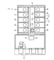
図1に示すように、液処理装置1は、複数枚のウエハW(被処理体、以下単にウエハWと記す)を収容したキャリアを載置するための複数の載置台21と、載置台21に載置されたキャリアからウエハWを取り出すための搬送アーム22と、搬送アームによって取り出されたウエハWを載置するための棚ユニット23と、棚ユニット23に載置されたウエハWを受け取り、当該ウエハWを後述する各液処理ユニット3内に搬送する搬送アーム24と、を備えている。このうち、搬送アーム24は、搬送路25内を移動自在に構成されており、この搬送路25の両側に、液処理部をなす複数の液処理ユニット3(3A〜3J)が設けられている。このようにして、搬送アーム25は、棚ユニット23と各液処理ユニット3との間を移動し、ウエハWを、液処理ユニット3に対して搬出入するようになっている。
As shown in FIG. 1, the liquid processing apparatus 1 includes a plurality of mounting tables 21 for mounting a carrier containing a plurality of wafers W (objects to be processed, hereinafter simply referred to as wafers W), and a mounting table 21. A
次に、図2を参照しながら液処理ユニット3の構成について説明する。液処理ユニット3は、ウエハWに対して複数種別の処理液を選択的に供給して、ウエハWを枚葉式に液処理するように構成されている。このような液処理ユニット3は、ウエハWを液処理する密閉された液処理空間31aを形成し、開口部31bを含むアウターチャンバ(液処理容器)31と、アウターチャンバ31に開閉自在に設けられ、開口部31bを介して処理液空間31aを開放可能な開閉パネル31cと、開閉パネル31cの開閉を検出するパネル検出部31dと、を有している。このうち、パネル検出部31dは、アウターチャンバ31に取り付けられてもよく、あるいは、開閉パネル31cに取り付けられてもよい。なお、各パネル検出部31dには、後述する制御部100(図3参照)が接続されている。また、図1に示すように、アウターチャンバ31には、ウエハWが搬入出されるウエハ搬入出口31eが設けられている。
Next, the configuration of the
アウターチャンバ31内には、液処理空間31a内にてウエハWをほぼ水平に保持した状態で回転させるウエハ保持機構32が設けられている。このウエハ保持機構32には、当該ウエハ保持機構32を駆動する回転駆動部32aが連結されている。また、ウエハ保持機構32の上方には、ウエハ保持機構32に保持されたウエハWの上面に処理液を選択的に供給するノズルアーム33が設けられており、ウエハ保持機構32の周囲には、回転するウエハWから周囲に飛散した薬液(処理液)を受けるためのインナーカップ34が設けられている。
In the
アウターチャンバ31には図示しないウエハ搬入出口31eを介して搬送アーム24(図1参照)によりウエハWが搬入出される。このアウターチャンバ31の底面には、当該アウターチャンバ31内の雰囲気を液処理ユニット3毎に排出するための個別排気路35が連結されると共に、アウターチャンバ31の底面に溜まったDIW液などの液体を排出するための排水路36が設けられている。インナーカップ34には、ウエハWから飛散してインナーカップ34にて受けた薬液を排出する排液路37が設けられている。また、ウエハ保持機構32の内部には薬液供給路38が形成されており、回転するウエハWの下面に当該薬液供給路38を介して薬液を供給するようになっている。
A wafer W is carried into and out of the
ノズルアーム33の先端部には、処理液供給用のノズル33aが設けられている。このノズル33aには、IPA供給部41、DIW供給部42、SC1供給部43、DHF供給部44が供給路45、46、47を介して連結されている。また、DIW供給部42、SC1供給部43、DHF供給部44は、供給路47、48を介して、ウエハ保持機構32の供給路38にも連結されている。
A
IPA供給部41は、高い揮発性を利用してウエハWを乾燥させるためのIPA(イソプロピルアルコール)液を供給し、DIW供給部42は、薬液処理後のウエハWに残存する薬液を除去するためのリンス液(処理液)であるDIW(Deionized Water)液を供給するようになっている。また、SC1供給部43は、ウエハW表面のパーティクルや有機性の汚染物質を除去するための薬液であるSC1液(アンモニアと過酸化水素水の混合液)を供給し、DHF供給部44は、ウエハW表面の自然酸化膜を除去するDHF液(希フッ酸水溶液:DHF(Diluted Hydrofluoric acid)液)を供給するように構成されている。図中、41aは、ノズル33aへのIPA液の供給量を調整するマスフローコントローラであり、40は切替弁、49a、49bは、各々ノズルアーム33側、ウエハ保持機構32側への処理液の供給量を調整するマスフローコントローラである。ここで、薬液の内、IPA液が有機系薬液、DHF液が酸性薬液、SC1液がアルカリ性薬液にそれぞれ相当する。
The
続いて、液処理ユニット3の排気系について説明する。本実施の形態においては、一例として、図1に示すように、搬送路24の両側に5つの液処理ユニット3がそれぞれ配列されているが、液処理ユニット3A〜3Eに対応する排気系と、液処理ユニット3F〜3Jに対応する排気系は、概略等しいため、ここでは、液処理ユニット3A〜3Eに対応する排気系について説明する。
Next, the exhaust system of the
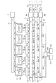
図3に示すように、各液処理ユニット3には、個別排気路35を介して、液処理ユニット3のアウターチャンバ31内の雰囲気を排出する共通排気路6が連結されている。この共通排気路6は、液処理ユニット3においてウエハWに対して供給される処理液の種別毎に液処理ユニット3のアウターチャンバ31内の雰囲気を排出する複数の専用共通排気路61〜63を有している。すなわち、図3に示す形態においては、共通排気路6は、乾燥処理時のアウターチャンバ31内の雰囲気を排出する第1専用共通排気路61と、アルカリ性薬液処理時のアウターチャンバ31内の雰囲気を排出する第2専用共通排気路62と、酸性薬液処理時のアウターチャンバ31内の雰囲気を排出する第3専用共通排気路63と、を有している。そして、各個別排気路35は、対応する液処理ユニット3と各専用共通排気路61〜63との間を連結するようになっている。
As shown in FIG. 3, each
各専用共通排気路61〜63には、各液処理ユニット3のアウターチャンバ31内からの排気量を調整するための排気ダンパー64が設けられている。各排気ダンパー64は、制御部100に接続され、この制御部100からの指令に基づいて、液処理ユニット3のアウターチャンバ31内からの排気量を所定量に設定可能になっている。
Each dedicated
また、各専用共通排気路61〜63に、排気ダンパー64よりも排気方向下流側において、液処理装置1の外部に設けられた排気駆動部110に連結されており、各専用共通排気路61〜63内を吸引して、各アウターチャンバ31内の雰囲気を排出し、図示しない回収設備に送られるようになっている。なお、図3においては、各液処理ユニット3からの排気の流れを明瞭に示すために模式的に示したものであり、各専用共通排気路61〜63の実際の配置を示したものではなく、各専用共通排気路61〜63の配置は、任意とすることができる。
Further, each dedicated
各個別排気路35には、開閉機構5が開閉自在に設けられている。本実施の形態においては、開閉機構5は、液処理ユニット3を、当該液処理ユニット3においてウエハWに対して供給される処理液の種別に対応した専用共通排気路61〜63に切り替えて連結する流路切替機構5を有している。この流路切替機構5は、液処理ユニット3と専用共通排気路61〜63とを連通する各流路を選択的に開閉することにより、流路を切り替えるものとして構成されている。このような流路切替機構5としては、例えば、(流体の流れが逆とはなるが)図2に示す切替弁40のように、3つの開閉弁を用いて構成してもよく、あるいは、これと同等の機能を有するような構造としてもよい。なお、各流路切替機構5には、制御部100が接続され、この制御部100からの指令に基づいて、各流路切替機構5が制御されるようになっている。
Each
各専用共通排気路61〜63には、外気を取り込む外気取込部65が設けられている。各外気取込部65は、図3に示すように、対応する専用共通排気路61〜63において、排気駆動部110とは反対側の端部に設けられている。なお、このような外気取込部65は、専用共通排気路61〜63の当該端部を外気に対して開放することにより構成することができる。
Each of the dedicated
また、各専用共通排気路61〜63には、外気取込部65から取り込まれる外気の流量を調整する取込量調整弁V11〜V13が設けられている。具体的には、第1専用共通排気路61に第1取込量調整弁V11が設けられ、第2専用共通排気路62に第2取込量調整弁V12が設けられ、第3専用共通排気路63に第3取込量調整弁V13が設けられている。各取込量調整弁V11〜V13は、対応する専用共通排気路61〜63において、各液処理ユニット3からの排気の合流点66a〜66eより、図3中に矢印で示す排気方向上流側に配置されている。すなわち、各液処理ユニット3A〜3Eからの排気は、専用共通排気路61〜63において合流点66a〜66eで合流するようになっているが、このうち排気方向上流側に配置されている合流点66aより排気方向上流側に、各取込量調整弁V11〜V13が配置されている。そして、各取込量調整弁V11〜V13よりさらに排気方向上流側に、外気取込部65が配置されている。なお、各取込量調整弁V11〜V13には制御部100が接続され、この制御部100からの指令に基づいて、各取込量調整弁V11〜V13の開度が制御されるようになっている。また、このような取込量調整弁V11〜V13は、例えば、バタフライバルブにより構成することができる。
The dedicated
各液処理ユニット3には、アウターチャンバ31に清浄な空気(気体)をダウンフローとして供給する単一のファンフィルターユニット(気体供給部、FFU)7が連結されている。各アウターチャンバ31とファンフィルターユニット7とは、気体供給路71を介して連結されており、ファンフィルターユニット7からの清浄な気体は、気体供給路71を介して、各アウターチャンバ31内に供給されるようになっている。このようにして、薬液から蒸発して気化したガスが、上昇して拡散することを防止すると共に、各液処理容器3内の清浄度を保っている。なお、ファンフィルターユニット7は、制御部100に接続され、この制御部100からの指令に基づいて、供給される清浄な空気の流量が制御されるようになっている。
Each
上述したように、流路切替機構5および取込量調整弁V11〜V13には、制御部100が接続されている。この制御部100は、各流路切替機構5の切替状態に基づいて、各取込量調整弁V11〜V13の開度を制御するようになっている。例えば、制御部100は、第1専用共通排気路61に連結されている液処理ユニット3の個数が減少するにつれて、第1取込量調整弁V11の開度を大きくするように、当該第1取込量調整弁V11を制御する。具体的には、第1専用共通排気路61に5つの個別排気路35が連結されている場合には、第1取込量調整弁V11の開度を第1の開度に調整する。第1専用共通排気路61に4つの個別排気路35が連結されている場合には、第1取込量調整弁V11の開度を第2の開度に調整する。同様にして、第1取込量調整弁V11の開度を、3つの個別排気路35が連結されている場合には第3の開度に、2つの個別排気路35が連結されている場合には第4の開度に、1つの個別排気路35が連結されている場合には第5の開度に、個別排気路35がいずれも連結されていない場合には、第6の開度に調整する。ここで上述した各角度の関係は、第1の開度<第2の開度<第3の開度<第4の開度<第5の開度<第6の開度となる。このようにして、外気取込部65から取り込まれる外気の流量を調整することにより、第1専用共通排気路61に連結されている液処理ユニット3のアウターチャンバ31からの排気量が変動することを抑制している。また、制御部100は、第2取込量調整弁V12および第3取込量調整弁V13についても、上述した第1取込量調整弁V11と同様にして、それぞれの開度を調整するようになっている。
As described above, the
また、制御部100は、上述したパネル検出部31dにより開閉パネル31cが開いたことが検出された場合、対応する流路切替機構5を制御するようになっている。すなわち、制御部100は、パネル検出部31dにより開閉パネル31cが開いていることが検出された場合、対応する開閉機構5を開くように、すなわち、対応する液処理ユニット3と各専用共通排気路61〜63のうちの一つの専用共通排気路が連通するように、流路切替機構5を制御する。この場合、制御部100は、この流路切替機構5の切替状態を、上述のようにして取込量調整弁V11〜V13の開度の調整に反映させる。
Further, the
さらに、制御部100は、上述したファンフィルターユニット7および排気ダンパー64をも制御しており、各液処理ユニット3のアウターチャンバ31の内圧が、所定の圧力(例えば、大気圧)に維持されるようになっている。
Furthermore, the
ところで、図3に示すように、制御部100には、工程管理者等が液処理装置1を管理するために、コマンドの入力操作等を行うキーボードや、液処理装置1の稼働状況等を可視化して表示するディスプレイ等からなる入出力装置101が接続されている。また、制御部100は、液処理装置1で実行される処理を実現するためのプログラム等が記録された記録媒体102にアクセス可能となっている。記録媒体102は、ROMおよびRAM等のメモリ、ハードディスク、CD−ROM、DVD−ROM、およびフレキシブルディスク等のディスク状記録媒体等、既知の記録媒体から構成され得る。このようにして、制御部100が、記録媒体102に予め記録されたプログラム等を実行することによって、液処理装置1においてウエハWの処理が行われるようになっている。
By the way, as shown in FIG. 3, in order to manage the liquid processing apparatus 1 by the process manager or the like, the
次に、このような構成からなる本実施の形態の作用、すなわち本実施の形態による液処理方法について説明する。なお、以下に説明する液処理方法を実行するための各構成要素の動作は、予め記録媒体102に記録されたプログラムに基づいた制御部100からの制御信号によって制御される。
Next, the operation of the present embodiment having such a configuration, that is, the liquid processing method according to the present embodiment will be described. The operation of each component for executing the liquid processing method described below is controlled by a control signal from the
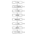
まず、図4に示すように、液処理ユニット3内にウエハWが搬入される(ステップS1)。この場合、まず、図1に示すように、ウエハWが収容されたキャリアが載置台21に載置され、搬送アーム22によりキャリア内からウエハWが取り出されて棚ユニット23に載置される。続いて、搬送アーム24が棚ユニット23からウエハWを受け取って、所定の液処理ユニット3のアウターチャンバ31内にウエハ搬入出口31eを介して搬入され、ウエハWがウエハ保持機構32に受け渡されて保持される。
First, as shown in FIG. 4, the wafer W is loaded into the liquid processing unit 3 (step S1). In this case, first, as shown in FIG. 1, the carrier containing the wafer W is placed on the placing table 21, and the wafer W is taken out from the carrier by the
続いて、ウエハ保持機構32に保持されたウエハWの上方に、ノズルアーム33のノズル33aが移動する。また、流路切替機構5により、液処理ユニット3のアウターチャンバ31が第2専用共通排気路62に切り替えられて連結され、ウエハ保持機構32が回転駆動部32aによって駆動され、ウエハWが回転する。なお、以下に述べるウエハWの液処理を行っている間、排気駆動部110は駆動され続ける。
Subsequently, the
次に、液処理ユニット3において、ウエハWに対して各種処理液が選択的に供給されて、ウエハWが液処理される。
Next, in the
まず、ウエハWがアルカリ性薬液処理される(ステップS2)。この場合、ノズル33a及び薬液供給路38によりウエハWの上下面にSC1液が供給される。このことにより、ウエハWの上下面がアルカリ洗浄される。この間、アウターチャンバ31内の雰囲気が、個別排気路35および第2専用共通排気路62を通って排出される。なお、アウターチャンバ31内には、ウエハWの回転によってSC1液が飛散している。このため、アウターチャンバ31内の雰囲気は、SC1液のミストと共に排出される。
First, the wafer W is treated with an alkaline chemical solution (step S2). In this case, the SC1 liquid is supplied to the upper and lower surfaces of the wafer W by the
アルカリ性薬液処理が終了した後、ノズル33a及び薬液供給路38によりウエハWの上下面にDIW液が供給され、ウエハWがリンス処理される(ステップS3)。その後、振切乾燥が行われる(ステップS4)。
After the alkaline chemical processing is completed, the DIW liquid is supplied to the upper and lower surfaces of the wafer W through the
次に、流路切替機構5により、アウターチャンバ31が第3専用共通排気路63に切り替えられて連結される。
Next, the
続いて、ウエハWが酸性薬液処理される(ステップS5)。この場合、ノズル33a及び薬液供給路38によりウエハWの上下面にDHF液が供給される。このことにより、ウエハWの上下面が酸洗浄される。この間、アウターチャンバ31内の雰囲気が、個別排気路35および第3専用共通排気路63を通って排出される。なお、アウターチャンバ31内には、ウエハWの回転によってDHF液が飛散している。このため、アウターチャンバ31内の雰囲気は、DHF液のミストと共に排出される。
Subsequently, the wafer W is processed with an acidic chemical solution (step S5). In this case, the DHF liquid is supplied to the upper and lower surfaces of the wafer W by the
酸性薬液処理が終了した後、ノズル33a及び薬液供給路38によりウエハWの上下面にDIW液が供給され、ウエハWがリンス処理される(ステップS6)。
After the acidic chemical solution processing is completed, the DIW solution is supplied to the upper and lower surfaces of the wafer W through the
その後、流路切替機構5により、アウターチャンバ31が第1専用共通排気路61に切り替えられて連結される。
Thereafter, the
続いて、ウエハWが乾燥処理される(ステップS7)。この場合、ノズル33aによりウエハWの上面にIPA液が供給される。このことにより、ウエハWの上面に残存するDIW液が除去されて、ウエハWが乾燥する。この間、アウターチャンバ31内の雰囲気が、個別排気路35および第1専用共通排気路61を通って排出される。なお、アウターチャンバ31内には、ウエハWの回転によってIPA液が飛散している。このため、アウターチャンバ31内の雰囲気は、IPA液のミストと共に排出される。
Subsequently, the wafer W is dried (step S7). In this case, the IPA liquid is supplied to the upper surface of the wafer W by the
このようにして、ウエハWの液処理が終了する。 In this way, the liquid processing of the wafer W is completed.
ところで、各液処理ユニット3における液処理の各ステップは、液処理ユニット3毎にそれぞれのタイミングで行われている。すなわち、各液処理ユニット3におけるアルカリ性薬液処理、酸性薬液処理および乾燥処理のタイミングがずれて、各流路切替機構5の切替状態が互いに異なっている場合がある。例えば、液処理ユニット3Aに対応する流路切替機構5が、当該液処理ユニット3Aを第1専用共通排気路61に連結し、液処理ユニット3Bに対応する流路切替機構5が、当該液処理ユニット3Bを第2専用共通排気路62に連結している場合が考えられる。
By the way, each step of the liquid processing in each
そこで、本実施の形態においては、ウエハWの液処理が行われている間、各流路切替機構5の切替状態に基づいて、各専用共通排気路61〜63に取り込まれる外気の流量を調整する取込量調整弁V11〜V13の開度が調整されている。具体的には、例えば、制御部100は、第1専用共通排気路61に連結されている液処理ユニット3の個数が減少するにつれて、第1取込量調整弁V11の開度を大きくするように、当該第1取込量調整弁V11を制御する。第2取込量調整弁V12および第3取込量調整弁V13も同様にして制御する。このことにより、各外気取込部65から各専用共通排気路61〜63に取り込まれる外気の流量が調整され、各アウターチャンバ31からの排気量が変動することを抑制している。
Therefore, in the present embodiment, the flow rate of the outside air taken into the dedicated
ウエハWの液処理が終了した後、ウエハWが入れ替えられる(ステップS8)。この場合、まず、アウターチャンバ31のウエハ搬入出口31eが開いて、アウターチャンバ31内に搬送アーム24が進入して処理後のウエハWが搬出される。搬出されたウエハWは、棚ユニット23に受け渡され、搬送アーム22によって載置台21上のキャリアに収容される。その後、処理前のウエハWをステップS1と同様にして搬入して液処理することにより、複数のウエハWを連続的に液処理することができる。
After the liquid processing of the wafer W is completed, the wafer W is replaced (step S8). In this case, first, the wafer loading / unloading
ところで、各液処理ユニット3内でウエハWの液処理が行われている間に、一部の液処理ユニット3のアウターチャンバ31の内部点検などを目的として、開閉パネル31cが開けられる場合がある。この場合には、まず、アウターチャンバ31に設けられたパネル検出部31dにより、開閉パネル31cが開いたことが検出される。次に、当該アウターチャンバ31に対応する個別排気路35を開くように、すなわち、当該液処理ユニット3のアウターチャンバ31と各専用共通排気路61〜63のうちの一の専用共通排気路とが連通するように、流路切替機構5が制御される。その後、この流路切替機構5の切替状態が、上述のようにして取込量調整弁V11〜V13の開度の調整に反映される。
By the way, while the liquid processing of the wafer W is being performed in each
このように本実施の形態によれば、各専用共通排気路61〜63に、外気を取り込む外気取込部65が設けられ、この外気取込部65から取り込まれる外気の取込量を調整する取込量調整弁V11〜V13が設けられて、各取込量調整弁V11〜V13の開度が、各流路切替機構5の切替状態に基づいて制御されている。このことにより、各液処理ユニット3におけるアルカリ性薬液処理、酸性薬液処理およびIPA乾燥処理のタイミングがずれて、各流路切替機構5の切替状態が互いに異なっている場合であっても、外気取込部65から取り込まれる外気の流量を調整することにより、各液処理ユニット3のアウターチャンバ31からの排気量が変動することを抑制することができる。このため、各アウターチャンバ31の内圧が変動して低下することを抑制することができる。この場合、例えば、アウターチャンバ31の内圧が低下してアウターチャンバ31内に外気が取り込まれて清浄度が低下することを防止することができる。
As described above, according to the present embodiment, the dedicated
また、本実施の形態によれば、例えば、液処理ユニット3のアウターチャンバ31の内部点検などを目的として、液処理ユニット3の開閉パネル31cが開いた場合、このことをパネル検出部31dが検出することにより、対応する流路切替機構5が、当該液処理ユニット3のアウターチャンバ31と各専用共通排気路61〜63のうちの一の専用共通排気路とが連通するように、制御される。このことにより、ファンフィルターユニット7から供給された空気を、個別排気路35に排出することができる。また、当該流路切替機構5を含む各流路切替機構5の切替状態に基づいて、取込量調整弁V11〜V13の開度が調整される。このことにより、例えば、一の液処理ユニット3の開閉パネル31cが開けられた場合であっても、他の液処理ユニット3のアウターチャンバ31からの排気量が変動することを抑制し、他の液処理ユニット3のアウターチャンバ31の内圧が変動することを抑制することができる。この場合、例えば、一の液処理ユニット3の内部点検を行いながら、他の液処理ユニット3においてウエハWの液処理を行うことができる。
Further, according to the present embodiment, for example, when the open /
以上、本発明による実施の形態について説明してきたが、当然のことながら、本発明の要旨の範囲内で、種々の変形も可能である。以下、代表的な変形例について説明する。 As mentioned above, although embodiment by this invention has been described, naturally, various deformation | transformation are also possible within the range of the summary of this invention. Hereinafter, typical modifications will be described.
すなわち、本実施の形態においては、各液処理ユニット3には、個別排気路35を介して各専用共通排気路61〜63が連結されている例について説明した。しかしながら、このことに限られることはない。例えば、個別排気路35が、液処理ユニット3においてウエハWに対して供給される処理液の種別毎にアウターチャンバ31内の雰囲気を排出する複数の専用個別排気路(図示せず)を有し、各液処理ユニット3に、各専用個別排気路を介して、対応する専用共通排気路61〜63が連結されるようにしてもよい。この場合、各専用個別排気路に開閉自在な開閉弁(図示せず)を設けて、当該3つの開閉弁により流路切替機構5を構成することができる。
That is, in the present embodiment, the example in which the dedicated
また、本実施の形態においては、3種類の処理液に応じて、3つの専用共通排気路61〜63が設けられ、開閉機構5が、液処理ユニット3を、処理液の種別に対応した専用共通排気路61〜63に切り替えて連結する例について説明した。しかしながらこのことに限られることはなく、共通排気路6が、単一の専用共通排気路からなり、開閉機構5が、個別排気路35、すなわち液処理ユニット3と当該単一の専用共通排気路との間の流路を単に開閉するように構成されていてもよい。この場合、制御部100は、当該開閉機構5の開閉状態に基づいて、各取込量調整弁V11〜V13の開度を制御すればよい。
In the present embodiment, three dedicated
また、本実施の形態においては、共通排気路6は、3つの専用共通排気路61〜63により構成される例について説明したが、液処理ユニット3において使用される処理液の種別数に応じて、2つまたは4つ以上の専用共通排気路により構成されていてもよい。
In the present embodiment, an example in which the common exhaust path 6 is configured by three dedicated
また、本実施の形態においては、外気取込部65および各取込量調整弁V11〜V13が、各液処理ユニット3からの排気の合流点66a〜66eより、排気方向上流側に配置されている例について説明した。しかしながらこのことに限られることはなく、外気取込部65および各取込量調整弁V11〜V13は、対応する専用共通排気路61〜63において任意の位置に配置することもできる。
Further, in the present embodiment, the outside
さらに、本実施の形態においては、アルカリ性薬液としてSC1液を用い、酸性薬液としてSC1液を用い、リンス液としてDIW液を用い、有機系薬液としてIPA液を用いる例について説明した。しかしながら、このことに限られることはなく、アルカリ性薬液としてアンモニア水等を用いても良く、酸性薬液としてHF(フッ化水素)やSC2(塩酸と過酸化水素水の混合溶液)等を用いても良い。また、リンス液および有機系薬液を含め、各処理液には一般に使用されている他の処理液を用いても良い。 Furthermore, in the present embodiment, the SC1 liquid is used as the alkaline chemical liquid, the SC1 liquid is used as the acidic chemical liquid, the DIW liquid is used as the rinsing liquid, and the IPA liquid is used as the organic chemical liquid. However, the present invention is not limited to this, and ammonia water or the like may be used as the alkaline chemical solution, and HF (hydrogen fluoride), SC2 (mixed solution of hydrochloric acid and hydrogen peroxide solution) or the like may be used as the acidic chemical solution. good. Moreover, you may use the other process liquid generally used for each process liquid including a rinse liquid and an organic type chemical | medical solution.
なお、以上の説明においては、本発明による液処理装置、液処理方法、およびこの液処理方法を実行するためのコンピュータプログラムが記録された記録媒体を、半導体ウエハWの洗浄処理に適用した例を示している。しかしながらこのことに限られることはなく、LCD基板またはCD基板等、種々の基板(被処理体)等の洗浄に本発明を適用することも可能である。 In the above description, the liquid processing apparatus, the liquid processing method, and the recording medium on which the computer program for executing the liquid processing method according to the present invention is recorded is applied to the cleaning process of the semiconductor wafer W. Show. However, the present invention is not limited to this, and the present invention can also be applied to cleaning various substrates (objects to be processed) such as an LCD substrate or a CD substrate.
1 液処理装置
3 液処理ユニット
31 アウターチャンバ
31a 液処理空間
31b 開口部
31c 開閉パネル
31d パネル検出部
35 個別排気路
5 開閉機構(流路切替機構)
6 共通排気路
61 第1専用共通排気路
62 第2専用共通排気路
63 第3専用共通排気路
65 外気取込部
66a〜66e 合流点
7 ファンフィルターユニット
100 制御部
102 記録媒体
V11 第1取込量調整弁
V12 第2取込量調整弁
V13 第3取込量調整弁
W ウエハ
DESCRIPTION OF SYMBOLS 1
6
Claims (11)
複数の前記液処理部内の雰囲気を排出する共通排気路と、
前記液処理部の各々と前記共通排気路とを連結する個別排気路と、
前記個別排気路に開閉自在に設けられた開閉機構と、
前記共通排気路に外気を取り込む外気取込部と、
前記共通排気路に設けられ、前記外気取込部から取り込まれる外気の流量を調整する取込量調整弁と、
前記開閉機構の各々の開閉状態に基づいて、前記取込量調整弁の開度を制御する制御部と、を備えたことを特徴とする液処理装置。 A plurality of liquid processing units for supplying a processing liquid to the object to be processed and liquid-treating the object to be processed;
A common exhaust passage for discharging the atmosphere in the plurality of liquid processing units;
An individual exhaust passage connecting each of the liquid processing units and the common exhaust passage;
An opening / closing mechanism provided in the individual exhaust passage so as to be freely opened and closed;
An outside air intake section for taking outside air into the common exhaust path;
An intake amount adjusting valve which is provided in the common exhaust passage and adjusts the flow rate of outside air taken in from the outside air taking-in portion;
A liquid processing apparatus comprising: a control unit that controls an opening degree of the intake amount adjusting valve based on an open / close state of each of the open / close mechanisms.
前記共通排気路は、前記液処理部において前記被処理体に対して供給される前記処理液の種別毎に前記液処理部内の雰囲気を排出する複数の専用共通排気路を有し、
前記個別排気路は、対応する前記液処理部と複数の前記専用共通排気路と連結するようになっており、
前記開閉機構は、前記被処理体に対して供給される前記処理液の種別に対応する前記専用共通排気路に前記液処理部を切り替えて連結する流路切替機構を有し、
前記専用共通排気路の各々に、外気を取り込む前記外気取込部が設けられ、
前記専用共通排気路の各々に、前記外気取込部から取り込まれる外気の流量を調整する前記取込量調整弁が設けられ、
前記制御部は、前記流路切替機構の各々の切替状態に基づいて、前記取込量調整弁の各々の開度を制御することを特徴とする請求項1または2に記載の液処理装置。 The liquid processing unit is configured to selectively supply a plurality of types of the processing liquid to the object to be processed,
The common exhaust path has a plurality of dedicated common exhaust paths for discharging the atmosphere in the liquid processing unit for each type of the processing liquid supplied to the object to be processed in the liquid processing unit,
The individual exhaust passage is adapted to be connected to the corresponding liquid processing section and a plurality of the dedicated common exhaust passages,
The opening / closing mechanism has a flow path switching mechanism that switches and connects the liquid processing unit to the dedicated common exhaust path corresponding to the type of the processing liquid supplied to the object to be processed.
Each of the dedicated common exhaust passages is provided with the outside air intake portion that takes in outside air,
Each of the dedicated common exhaust passages is provided with the intake amount adjustment valve for adjusting the flow rate of the outside air taken in from the outside air taking-in portion,
The liquid processing apparatus according to claim 1, wherein the control unit controls an opening degree of each of the intake amount adjusting valves based on a switching state of each of the flow path switching mechanisms.
前記制御部は、前記パネル検出部により前記開閉パネルが開いたことが検出された場合、対応する前記開閉機構を開くように制御することを特徴とする請求項1乃至4のいずれかに記載の液処理装置。 Each liquid processing section includes a liquid processing container that forms a liquid processing space for liquid processing the object to be processed, an openable / closable panel that can be opened and closed in the liquid processing container and can open the liquid processing space, and the open / close A panel detector for detecting opening and closing of the panel,
5. The control unit according to claim 1, wherein when the panel detection unit detects that the opening / closing panel is opened, the control unit controls the corresponding opening / closing mechanism to open. Liquid processing equipment.
前記液処理部に前記被処理体を搬入する工程と、
前記被処理体が搬入された前記液処理部において、前記被処理体に対して処理液を供給して前記被処理体を液処理する工程と、を備え、
前記被処理体を液処理する工程において、前記液処理部の雰囲気が前記個別排気路および前記共通排気路を通って排出されると共に、前記開閉機構の各々の開閉状態に基づいて、前記取込量調整弁の開度が調整されることを特徴とする液処理方法。 A plurality of liquid processing units for supplying a processing liquid to the object to be processed and liquid-processing the object to be processed; a common exhaust passage for discharging the atmosphere in the plurality of liquid processing units; and each of the liquid processing units An individual exhaust path connecting the common exhaust path, an open / close mechanism provided in the individual exhaust path, an outside air intake section for taking outside air into the common exhaust path, and an outside air intake provided in the common exhaust path. In a liquid processing method for liquid processing the object to be processed, using a liquid processing apparatus comprising an intake amount adjustment valve that adjusts the flow rate of outside air taken in from the intake section,
Carrying the object to be processed into the liquid processing unit;
A step of supplying a processing liquid to the object to be processed and liquid-treating the object to be processed in the liquid processing unit into which the object is carried;
In the step of liquid-treating the object to be treated, the atmosphere of the liquid treatment unit is discharged through the individual exhaust passage and the common exhaust passage, and the intake is performed based on each open / close state of the open / close mechanism. The liquid processing method characterized by adjusting the opening degree of a quantity adjustment valve.
前記共通排気路は、前記液処理部において前記被処理体に対して供給される前記処理液の種別毎に前記液処理部内の雰囲気を排出する複数の専用共通排気路を有し、
前記個別排気路は、対応する前記液処理部と複数の前記専用共通排気路とを連結するようになっており、
前記開閉機構は、前記被処理体に対して供給される前記処理液の種別に対応する前記専用共通排気路に前記液処理部を切り替えて連結する流路切替機構を有し、
前記専用共通排気路の各々に、外気を取り込む前記外気取込部が設けられ、
前記専用共通排気路の各々に、前記外気取込部から取り込まれる外気の流量を調整する前記取込量調整弁が設けられ、
前記被処理体を液処理する工程において、前記流路切替機構の各々の切替状態に基づいて、前記取込量調整弁の各々の開度が調整されることを特徴とする請求項6または7に記載の液処理方法。 The liquid processing unit is configured to selectively supply a plurality of types of the processing liquid to the object to be processed,
The common exhaust path has a plurality of dedicated common exhaust paths for discharging the atmosphere in the liquid processing unit for each type of the processing liquid supplied to the object to be processed in the liquid processing unit,
The individual exhaust path is configured to connect the corresponding liquid processing unit and a plurality of the dedicated common exhaust paths,
The opening / closing mechanism has a flow path switching mechanism that switches and connects the liquid processing unit to the dedicated common exhaust path corresponding to the type of the processing liquid supplied to the object to be processed.
Each of the dedicated common exhaust passages is provided with the outside air intake portion that takes in outside air,
Each of the dedicated common exhaust passages is provided with the intake amount adjustment valve for adjusting the flow rate of the outside air taken in from the outside air taking-in portion,
8. The opening degree of each of the intake amount adjusting valves is adjusted based on the switching state of each of the flow path switching mechanisms in the step of liquid-treating the object to be processed. The liquid processing method as described in any one of.
前記被処理体を液処理する工程において、前記パネル検出部により前記開閉パネルが開いたことが検出された場合、対応する前記開閉機構を開くように制御することを特徴とする請求項6乃至9のいずれかに記載の液処理方法。 Each liquid processing section includes a liquid processing container that forms a liquid processing space for liquid processing the object to be processed, an openable / closable panel that can be opened and closed in the liquid processing container and can open the liquid processing space, and the open / close A panel detector for detecting opening and closing of the panel,
10. In the step of liquid-treating the object to be processed, when the panel detection unit detects that the open / close panel is opened, the corresponding open / close mechanism is controlled to open. The liquid processing method in any one of.
この液処理方法は、
被処理体に対して処理液を供給して前記被処理体を液処理する複数の液処理部と、複数の前記液処理部内の雰囲気を排出する共通排気路と、前記液処理部の各々と前記共通排気路とを連結する個別排気路と、前記個別排気路に設けられた開閉機構と、前記共通排気路に外気を取り込む外気取込部と、前記共通排気路に設けられ、前記外気取込部から取り込まれる外気の流量を調整する取込量調整弁と、を備えた液処理装置を用いて、前記被処理体を液処理する液処理方法において、
前記液処理部に前記被処理体を搬入する工程と、
前記被処理体が搬入された前記液処理部において、前記被処理体に対して処理液を供給して前記被処理体を液処理する工程と、を備え、
前記被処理体を液処理する工程において、前記液処理部の雰囲気が前記個別排気路および前記共通排気路を通って排出されると共に、前記開閉機構の各々の開閉状態に基づいて、前記取込量調整弁の開度が調整されることを特徴とする記録媒体。 A recording medium on which a computer program for executing a liquid processing method is recorded,
This liquid treatment method
A plurality of liquid processing units for supplying a processing liquid to the object to be processed and liquid-processing the object to be processed; a common exhaust passage for discharging the atmosphere in the plurality of liquid processing units; and each of the liquid processing units An individual exhaust path connecting the common exhaust path, an open / close mechanism provided in the individual exhaust path, an outside air intake section for taking outside air into the common exhaust path, and an outside air intake provided in the common exhaust path. In a liquid processing method for liquid processing the object to be processed, using a liquid processing apparatus comprising an intake amount adjustment valve that adjusts the flow rate of outside air taken in from the intake section,
Carrying the object to be processed into the liquid processing unit;
A step of supplying a processing liquid to the object to be processed and liquid-treating the object to be processed in the liquid processing unit into which the object is carried;
In the step of liquid-treating the object to be treated, the atmosphere of the liquid treatment unit is discharged through the individual exhaust passage and the common exhaust passage, and the intake is performed based on each open / close state of the open / close mechanism. A recording medium, characterized in that the opening of the amount adjusting valve is adjusted.
Priority Applications (4)
| Application Number | Priority Date | Filing Date | Title |
|---|---|---|---|
| JP2011050389A JP5474853B2 (en) | 2011-03-08 | 2011-03-08 | Liquid processing apparatus, liquid processing method, and recording medium on which a computer program for executing the liquid processing method is recorded |
| KR1020110040843A KR101524334B1 (en) | 2011-03-08 | 2011-04-29 | Liquid processing apparatus, liquid processing method and recording medium having computer program for performing the same method |
| US13/161,236 US9073103B2 (en) | 2011-03-08 | 2011-06-15 | Liquid processing apparatus, liquid processing method, and recording medium having computer program for performing the same method |
| TW100128228A TWI500101B (en) | 2011-03-08 | 2011-08-08 | Liquid processing apparatus, liquid processing method, and recording medium on which a program for executing the liquid processing method is recorded |
Applications Claiming Priority (1)
| Application Number | Priority Date | Filing Date | Title |
|---|---|---|---|
| JP2011050389A JP5474853B2 (en) | 2011-03-08 | 2011-03-08 | Liquid processing apparatus, liquid processing method, and recording medium on which a computer program for executing the liquid processing method is recorded |
Publications (3)
| Publication Number | Publication Date |
|---|---|
| JP2012190823A true JP2012190823A (en) | 2012-10-04 |
| JP2012190823A5 JP2012190823A5 (en) | 2013-03-28 |
| JP5474853B2 JP5474853B2 (en) | 2014-04-16 |
Family
ID=46794398
Family Applications (1)
| Application Number | Title | Priority Date | Filing Date |
|---|---|---|---|
| JP2011050389A Active JP5474853B2 (en) | 2011-03-08 | 2011-03-08 | Liquid processing apparatus, liquid processing method, and recording medium on which a computer program for executing the liquid processing method is recorded |
Country Status (4)
| Country | Link |
|---|---|
| US (1) | US9073103B2 (en) |
| JP (1) | JP5474853B2 (en) |
| KR (1) | KR101524334B1 (en) |
| TW (1) | TWI500101B (en) |
Cited By (10)
| Publication number | Priority date | Publication date | Assignee | Title |
|---|---|---|---|---|
| WO2014103523A1 (en) * | 2012-12-28 | 2014-07-03 | 大日本スクリーン製造株式会社 | Treatment device, exhaust switching device therefor, exhaust switching unit and switching valve box |
| JP2014139970A (en) * | 2013-01-21 | 2014-07-31 | Dainippon Screen Mfg Co Ltd | Substrate processing device |
| JP2016092144A (en) * | 2014-10-31 | 2016-05-23 | 東京エレクトロン株式会社 | Substrate liquid processing apparatus, exhaust switching unit, and substrate liquid processing method |
| JP2016092143A (en) * | 2014-10-31 | 2016-05-23 | 東京エレクトロン株式会社 | Substrate liquid processing apparatus |
| KR20170015162A (en) | 2015-07-29 | 2017-02-08 | 도쿄엘렉트론가부시키가이샤 | Liquid processing apparatus |
| WO2017094406A1 (en) * | 2015-12-04 | 2017-06-08 | 株式会社 荏原製作所 | Exhaust device for substrate processing device |
| WO2019031590A1 (en) * | 2017-08-10 | 2019-02-14 | 株式会社荏原製作所 | Substrate processing device |
| JP2021136435A (en) * | 2020-02-26 | 2021-09-13 | 株式会社Screenホールディングス | Substrate processing device |
| JP2023024746A (en) * | 2018-09-21 | 2023-02-16 | 株式会社Screenホールディングス | Substrate processing apparatus |
| US12512342B2 (en) | 2020-02-26 | 2025-12-30 | SCREEN Holdings Co., Ltd. | Substrate treating apparatus |
Families Citing this family (12)
| Publication number | Priority date | Publication date | Assignee | Title |
|---|---|---|---|---|
| US9446467B2 (en) * | 2013-03-14 | 2016-09-20 | Taiwan Semiconductor Manufacturing Company, Ltd. | Integrate rinse module in hybrid bonding platform |
| JP6281161B2 (en) * | 2013-09-27 | 2018-02-21 | 東京エレクトロン株式会社 | Liquid processing equipment |
| KR101910802B1 (en) * | 2016-09-30 | 2018-10-25 | 세메스 주식회사 | Substrate treating apparatus and substrate treating method |
| JP6920849B2 (en) * | 2017-03-27 | 2021-08-18 | 株式会社荏原製作所 | Substrate processing method and equipment |
| JP6953286B2 (en) * | 2017-11-09 | 2021-10-27 | 東京エレクトロン株式会社 | Substrate processing equipment, substrate processing method and storage medium |
| JP6956603B2 (en) * | 2017-11-13 | 2021-11-02 | 東京エレクトロン株式会社 | Substrate processing equipment, substrate processing method and storage medium |
| KR102121240B1 (en) * | 2018-05-03 | 2020-06-18 | 세메스 주식회사 | Apparatus and Method for treating substrate |
| JP7189013B2 (en) * | 2018-12-28 | 2022-12-13 | 東京エレクトロン株式会社 | SUBSTRATE PROCESSING APPARATUS AND METHOD OF OPERATION OF SUBSTRATE PROCESSING APPARATUS |
| JP7314634B2 (en) | 2019-06-11 | 2023-07-26 | 東京エレクトロン株式会社 | Coating device and coating method |
| JP7370277B2 (en) | 2020-02-26 | 2023-10-27 | 株式会社Screenホールディングス | Substrate processing equipment |
| JP7444701B2 (en) * | 2020-05-28 | 2024-03-06 | 株式会社Screenホールディングス | Substrate processing device, substrate processing method, learning data generation method, learning method, learning device, learned model generation method, and learned model |
| KR102737433B1 (en) * | 2022-12-16 | 2024-12-02 | 세메스 주식회사 | Control unit and semiconductor manufacturing equipment including the same |
Citations (5)
| Publication number | Priority date | Publication date | Assignee | Title |
|---|---|---|---|---|
| JPH0737778A (en) * | 1993-07-19 | 1995-02-07 | Hitachi Ltd | Exhaust control system |
| JPH10312952A (en) * | 1997-05-14 | 1998-11-24 | Dainippon Screen Mfg Co Ltd | Substrate processing equipment |
| JPH113851A (en) * | 1997-06-11 | 1999-01-06 | Tokyo Electron Ltd | Liquid processing apparatus and liquid processing method |
| JP2000208472A (en) * | 1999-01-18 | 2000-07-28 | Sony Corp | Washing sink |
| JP2009252884A (en) * | 2008-04-03 | 2009-10-29 | Tokyo Electron Ltd | Pressure control mechanism, substrate processing device, substrate processing method and storage medium |
Family Cites Families (4)
| Publication number | Priority date | Publication date | Assignee | Title |
|---|---|---|---|---|
| US20090017733A1 (en) * | 2005-04-19 | 2009-01-15 | Ebara Corporation | Substrate processing apparatus |
| JP4767783B2 (en) | 2006-07-26 | 2011-09-07 | 東京エレクトロン株式会社 | Liquid processing equipment |
| JP5369538B2 (en) * | 2008-08-12 | 2013-12-18 | 東京エレクトロン株式会社 | Liquid processing apparatus, liquid processing method, and storage medium |
| JP2010186974A (en) | 2009-02-13 | 2010-08-26 | Tokyo Electron Ltd | Liquid treatment device, liquid treatment method, and storage medium |
-
2011
- 2011-03-08 JP JP2011050389A patent/JP5474853B2/en active Active
- 2011-04-29 KR KR1020110040843A patent/KR101524334B1/en active Active
- 2011-06-15 US US13/161,236 patent/US9073103B2/en active Active
- 2011-08-08 TW TW100128228A patent/TWI500101B/en active
Patent Citations (5)
| Publication number | Priority date | Publication date | Assignee | Title |
|---|---|---|---|---|
| JPH0737778A (en) * | 1993-07-19 | 1995-02-07 | Hitachi Ltd | Exhaust control system |
| JPH10312952A (en) * | 1997-05-14 | 1998-11-24 | Dainippon Screen Mfg Co Ltd | Substrate processing equipment |
| JPH113851A (en) * | 1997-06-11 | 1999-01-06 | Tokyo Electron Ltd | Liquid processing apparatus and liquid processing method |
| JP2000208472A (en) * | 1999-01-18 | 2000-07-28 | Sony Corp | Washing sink |
| JP2009252884A (en) * | 2008-04-03 | 2009-10-29 | Tokyo Electron Ltd | Pressure control mechanism, substrate processing device, substrate processing method and storage medium |
Cited By (23)
| Publication number | Priority date | Publication date | Assignee | Title |
|---|---|---|---|---|
| WO2014103523A1 (en) * | 2012-12-28 | 2014-07-03 | 大日本スクリーン製造株式会社 | Treatment device, exhaust switching device therefor, exhaust switching unit and switching valve box |
| JPWO2014103523A1 (en) * | 2012-12-28 | 2017-01-12 | 株式会社Screenホールディングス | Processing device, exhaust gas switching device, exhaust gas switching unit and switching valve box |
| US10471479B2 (en) | 2012-12-28 | 2019-11-12 | SCREEN Holdings Co., Ltd. | Treatment device and exhaust switching device therefor, and exhaust switching unit and switching valve box |
| JP2014139970A (en) * | 2013-01-21 | 2014-07-31 | Dainippon Screen Mfg Co Ltd | Substrate processing device |
| JP2016092144A (en) * | 2014-10-31 | 2016-05-23 | 東京エレクトロン株式会社 | Substrate liquid processing apparatus, exhaust switching unit, and substrate liquid processing method |
| JP2016092143A (en) * | 2014-10-31 | 2016-05-23 | 東京エレクトロン株式会社 | Substrate liquid processing apparatus |
| KR20170015162A (en) | 2015-07-29 | 2017-02-08 | 도쿄엘렉트론가부시키가이샤 | Liquid processing apparatus |
| JP2017033988A (en) * | 2015-07-29 | 2017-02-09 | 東京エレクトロン株式会社 | Liquid processing equipment |
| US10046372B2 (en) | 2015-07-29 | 2018-08-14 | Tokyo Electron Limited | Liquid processing apparatus |
| WO2017094406A1 (en) * | 2015-12-04 | 2017-06-08 | 株式会社 荏原製作所 | Exhaust device for substrate processing device |
| JP2019036573A (en) * | 2017-08-10 | 2019-03-07 | 株式会社荏原製作所 | Substrate processing equipment |
| WO2019031590A1 (en) * | 2017-08-10 | 2019-02-14 | 株式会社荏原製作所 | Substrate processing device |
| CN111201596A (en) * | 2017-08-10 | 2020-05-26 | 株式会社荏原制作所 | Substrate processing apparatus |
| US11869788B2 (en) | 2017-08-10 | 2024-01-09 | Ebara Corporation | Substrate processing device |
| JP2023024746A (en) * | 2018-09-21 | 2023-02-16 | 株式会社Screenホールディングス | Substrate processing apparatus |
| JP7394203B2 (en) | 2018-09-21 | 2023-12-07 | 株式会社Screenホールディングス | Substrate processing equipment |
| JP2024009266A (en) * | 2018-09-21 | 2024-01-19 | 株式会社Screenホールディングス | Substrate processing equipment |
| US11915945B2 (en) | 2018-09-21 | 2024-02-27 | SCREEN Holdings Co., Ltd. | Substrate processing apparatus |
| JP7572532B2 (en) | 2018-09-21 | 2024-10-23 | 株式会社Screenホールディングス | Substrate Processing Equipment |
| US12456634B2 (en) | 2018-09-21 | 2025-10-28 | SCREEN Holdings Co., Ltd. | Substrate processing apparatus |
| JP2021136435A (en) * | 2020-02-26 | 2021-09-13 | 株式会社Screenホールディングス | Substrate processing device |
| JP7502157B2 (en) | 2020-02-26 | 2024-06-18 | 株式会社Screenホールディングス | Substrate Processing Equipment |
| US12512342B2 (en) | 2020-02-26 | 2025-12-30 | SCREEN Holdings Co., Ltd. | Substrate treating apparatus |
Also Published As
| Publication number | Publication date |
|---|---|
| JP5474853B2 (en) | 2014-04-16 |
| TW201237985A (en) | 2012-09-16 |
| US20120227768A1 (en) | 2012-09-13 |
| TWI500101B (en) | 2015-09-11 |
| KR20120102477A (en) | 2012-09-18 |
| KR101524334B1 (en) | 2015-05-29 |
| US9073103B2 (en) | 2015-07-07 |
Similar Documents
| Publication | Publication Date | Title |
|---|---|---|
| JP5474853B2 (en) | Liquid processing apparatus, liquid processing method, and recording medium on which a computer program for executing the liquid processing method is recorded | |
| TWI720261B (en) | Substrate processing device, substrate processing method and recording medium | |
| US11344931B2 (en) | Method of removing particles of substrate processing apparatus, and substrate processing apparatus | |
| JP7493325B2 (en) | Substrate Processing Equipment | |
| US8509937B2 (en) | Processing apparatus and operating method therefor | |
| JP5477131B2 (en) | Substrate processing equipment | |
| TWI775948B (en) | Substrate processing device | |
| JP5505384B2 (en) | Substrate processing apparatus, substrate processing method, and storage medium | |
| JP5425745B2 (en) | Liquid processing apparatus, liquid processing method, and recording medium on which a computer program for executing the liquid processing method is recorded | |
| JP2012190823A5 (en) | ||
| JP2011222595A (en) | Substrate processing apparatus, substrate processing method, and storage medium | |
| US12142474B2 (en) | Substrate processing method and substrate processing system | |
| JP2014197592A (en) | Substrate processor | |
| WO2013054849A1 (en) | Substrate processing device | |
| KR102406827B1 (en) | Substrate processing apparatus and substrate processing method | |
| JP6489524B2 (en) | Substrate processing equipment | |
| TW202014252A (en) | Substrate processing device and substrate processing method | |
| JP6593920B2 (en) | Substrate processing method and substrate processing apparatus | |
| JP2019140307A (en) | Substrate processing apparatus | |
| JP2006278955A (en) | Method and device for substrate processing | |
| CN209804605U (en) | Liquid treatment device | |
| KR100521401B1 (en) | System for wafer cleaning | |
| KR102845883B1 (en) | coating and developing device | |
| JP2011222676A (en) | Substrate treatment apparatus | |
| JPH11253894A (en) | Substrate treating device |
Legal Events
| Date | Code | Title | Description |
|---|---|---|---|
| A521 | Request for written amendment filed |
Free format text: JAPANESE INTERMEDIATE CODE: A523 Effective date: 20130213 |
|
| A621 | Written request for application examination |
Free format text: JAPANESE INTERMEDIATE CODE: A621 Effective date: 20130213 |
|
| A977 | Report on retrieval |
Free format text: JAPANESE INTERMEDIATE CODE: A971007 Effective date: 20130605 |
|
| A131 | Notification of reasons for refusal |
Free format text: JAPANESE INTERMEDIATE CODE: A131 Effective date: 20130611 |
|
| A521 | Request for written amendment filed |
Free format text: JAPANESE INTERMEDIATE CODE: A523 Effective date: 20130806 |
|
| TRDD | Decision of grant or rejection written | ||
| A01 | Written decision to grant a patent or to grant a registration (utility model) |
Free format text: JAPANESE INTERMEDIATE CODE: A01 Effective date: 20140107 |
|
| A61 | First payment of annual fees (during grant procedure) |
Free format text: JAPANESE INTERMEDIATE CODE: A61 Effective date: 20140205 |
|
| R150 | Certificate of patent or registration of utility model |
Ref document number: 5474853 Country of ref document: JP Free format text: JAPANESE INTERMEDIATE CODE: R150 Free format text: JAPANESE INTERMEDIATE CODE: R150 |
|
| R250 | Receipt of annual fees |
Free format text: JAPANESE INTERMEDIATE CODE: R250 |
|
| R250 | Receipt of annual fees |
Free format text: JAPANESE INTERMEDIATE CODE: R250 |
|
| R250 | Receipt of annual fees |
Free format text: JAPANESE INTERMEDIATE CODE: R250 |
|
| R250 | Receipt of annual fees |
Free format text: JAPANESE INTERMEDIATE CODE: R250 |
|
| R250 | Receipt of annual fees |
Free format text: JAPANESE INTERMEDIATE CODE: R250 |
|
| R250 | Receipt of annual fees |
Free format text: JAPANESE INTERMEDIATE CODE: R250 |
|
| R250 | Receipt of annual fees |
Free format text: JAPANESE INTERMEDIATE CODE: R250 |
|
| R250 | Receipt of annual fees |
Free format text: JAPANESE INTERMEDIATE CODE: R250 |