JP2012183694A - Liquid discharging device and method for controlling the same - Google Patents
Liquid discharging device and method for controlling the same Download PDFInfo
- Publication number
- JP2012183694A JP2012183694A JP2011047523A JP2011047523A JP2012183694A JP 2012183694 A JP2012183694 A JP 2012183694A JP 2011047523 A JP2011047523 A JP 2011047523A JP 2011047523 A JP2011047523 A JP 2011047523A JP 2012183694 A JP2012183694 A JP 2012183694A
- Authority
- JP
- Japan
- Prior art keywords
- liquid
- nozzles
- circulation path
- control
- sealing
- Prior art date
- Legal status (The legal status is an assumption and is not a legal conclusion. Google has not performed a legal analysis and makes no representation as to the accuracy of the status listed.)
- Granted
Links
Images


Classifications
-
- B—PERFORMING OPERATIONS; TRANSPORTING
- B41—PRINTING; LINING MACHINES; TYPEWRITERS; STAMPS
- B41J—TYPEWRITERS; SELECTIVE PRINTING MECHANISMS, i.e. MECHANISMS PRINTING OTHERWISE THAN FROM A FORME; CORRECTION OF TYPOGRAPHICAL ERRORS
- B41J2/00—Typewriters or selective printing mechanisms characterised by the printing or marking process for which they are designed
- B41J2/005—Typewriters or selective printing mechanisms characterised by the printing or marking process for which they are designed characterised by bringing liquid or particles selectively into contact with a printing material
- B41J2/01—Ink jet
- B41J2/17—Ink jet characterised by ink handling
- B41J2/175—Ink supply systems ; Circuit parts therefor
-
- B—PERFORMING OPERATIONS; TRANSPORTING
- B41—PRINTING; LINING MACHINES; TYPEWRITERS; STAMPS
- B41J—TYPEWRITERS; SELECTIVE PRINTING MECHANISMS, i.e. MECHANISMS PRINTING OTHERWISE THAN FROM A FORME; CORRECTION OF TYPOGRAPHICAL ERRORS
- B41J2/00—Typewriters or selective printing mechanisms characterised by the printing or marking process for which they are designed
- B41J2/005—Typewriters or selective printing mechanisms characterised by the printing or marking process for which they are designed characterised by bringing liquid or particles selectively into contact with a printing material
- B41J2/01—Ink jet
- B41J2/135—Nozzles
- B41J2/165—Preventing or detecting of nozzle clogging, e.g. cleaning, capping or moistening for nozzles
- B41J2/16505—Caps, spittoons or covers for cleaning or preventing drying out
Abstract
Description
本発明は、液体吐出装置およびその制御方法に関する。 The present invention relates to a liquid ejection apparatus and a control method thereof.
従来、この種の液体吐出装置としては、インクを噴射する印字ヘッドと、インクを収容するインクタンクと、インクタンクから印字ヘッドのマニホールドにインクを供給するための第1のインク流路と、マニホールドからインクタンクにインクを回収するための第2のインク流路と、第1のインク流路に設けられたインク循環用ポンプと、第2のインク流路に設けられた開閉バルブと、印字ヘッドのノズル面を覆うための吸引キャップと、吸引キャップに吸引パイプを介して接続された吸引用ポンプと、を備えるものが提案されている(例えば、特許文献1参照)。この装置では、印字ヘッドにインクを充填する際には、まず、吸引キャップによって印字ヘッドのノズル面を覆うと共に開閉バルブを開放してインク循環用ポンプを回転駆動することにより、インクを第1のインク流路,マニホールド,第2のインク流路からなる循環流路を循環させる。そして、その後に、開閉バルブを閉鎖すると共にインク循環用ポンプを第1のインク流路を閉塞しない状態で停止して吸引用ポンプを駆動することにより、印字ヘッドのインクを吸引して印字ヘッドの各圧力室にインクを充填させている。 Conventionally, this type of liquid ejecting apparatus includes a print head that ejects ink, an ink tank that contains ink, a first ink flow path for supplying ink from the ink tank to the manifold of the print head, and a manifold A second ink channel for collecting ink from the ink tank to the ink tank, an ink circulation pump provided in the first ink channel, an open / close valve provided in the second ink channel, and a print head Has been proposed that includes a suction cap for covering the nozzle surface of the nozzle and a suction pump connected to the suction cap via a suction pipe (see, for example, Patent Document 1). In this apparatus, when the print head is filled with ink, first, the nozzle surface of the print head is covered with the suction cap, and the opening and closing valve is opened to rotate the ink circulation pump, whereby the ink is supplied to the first print head. A circulation channel comprising an ink channel, a manifold, and a second ink channel is circulated. After that, by closing the open / close valve and stopping the ink circulation pump without closing the first ink flow path and driving the suction pump, the ink of the print head is sucked to Each pressure chamber is filled with ink.
吸引キャップは、一般に、印字ヘッドからインクを吸引する際などにノズル面を覆うためのものであり、ノズル面を覆うときにノズル面とによって閉空間を形成するものである。このため、印字ヘッドにインクを充填する際に、吸引キャップによってノズル面を覆っった状態で循環用ポンプを回転駆動する場合、インクの流速によってはノズルからインクが漏れ出てしまう場合がある。 The suction cap is generally for covering the nozzle surface when sucking ink from the print head, and forms a closed space with the nozzle surface when covering the nozzle surface. For this reason, when the circulation pump is driven to rotate while the nozzle surface is covered with the suction cap when the print head is filled with ink, the ink may leak from the nozzle depending on the flow rate of the ink.
本発明の液体吐出装置およびその制御方法は、複数のノズルを含む吐出ヘッドに液体を充填する際の液体の無駄を抑制することを主目的とする。 The main object of the liquid ejection apparatus and the control method thereof according to the present invention is to suppress waste of liquid when filling an ejection head including a plurality of nozzles.
本発明の液体吐出装置およびその制御方法は、上述の主目的を達成するために以下の手段を採った。 The liquid ejection apparatus and the control method thereof according to the present invention employ the following means in order to achieve the main object described above.
本発明の第1の液体吐出装置は、
液体を吐出する複数のノズルを有する吐出ヘッドを備える液体吐出装置であって、
液体を貯留する貯留部と、
前記吐出ヘッドを含んで構成され、一方の開口端部と他方の開口端部とが共に前記貯留部内に配置された循環路と、
前記循環路における前記吐出ヘッドより前記一方の開口端部側に設けられ、液体が前記循環路を循環するよう液体を圧送可能な圧送手段と、
前記複数のノズルをそれぞれ独立して封止可能な封止手段と、
前記貯留部を加圧可能な加圧手段と、
前記吐出ヘッドに液体を充填する際、前記封止手段によって前記複数のノズルがそれぞれ独立して封止された状態で前記圧送手段の駆動によって液体が前記循環路を循環するよう前記封止手段と前記圧送手段とを制御する第1制御を実行し、該第1制御の実行後に、前記加圧手段によって前記貯留部が加圧されながら前記封止手段による前記複数のノズルの封止が解除されるよう前記加圧手段と前記封止手段とを制御する第2制御を実行する充填時制御手段と、
を備えることを要旨とする。
The first liquid ejection apparatus of the present invention is
A liquid discharge apparatus comprising a discharge head having a plurality of nozzles for discharging liquid,
A reservoir for storing liquid;
A circulation path configured to include the discharge head, wherein one opening end and the other opening end are both disposed in the storage unit;
A pressure-feeding means that is provided closer to the one opening end than the discharge head in the circulation path and capable of pumping the liquid so that the liquid circulates in the circulation path;
Sealing means capable of independently sealing the plurality of nozzles;
Pressurizing means capable of pressurizing the reservoir,
When the discharge head is filled with liquid, the sealing means is configured so that the liquid circulates through the circulation path by driving the pressure feeding means in a state where the plurality of nozzles are independently sealed by the sealing means. The first control for controlling the pressure feeding unit is performed, and after the first control is performed, the sealing of the plurality of nozzles by the sealing unit is released while the reservoir is pressurized by the pressure unit. Filling control means for executing a second control for controlling the pressurizing means and the sealing means;
It is a summary to provide.
この本発明の第1の液体吐出装置では、吐出ヘッドに液体を充填する際には、封止手段によって複数のノズルがそれぞれ独立して封止された状態で圧送手段の駆動によって液体が循環路を循環するよう封止手段と圧送手段とを制御する第1制御を実行し、第1制御の実行後に、加圧手段によって貯留部が加圧されながら封止手段による複数のノズルの封止が解除されるよう加圧手段と封止手段とを制御する第2制御を実行する。まず、第1制御として複数のノズルを封止した状態で液体を循環路を循環させることにより、複数のノズルから液体が放出される(漏れ出る)のを抑止しながら吐出ヘッドに液体を充填することができる。このとき、複数のノズルの形状などによっては複数のノズル内の気体(気泡)が開口端部側に移動せずにそのまま残留する可能性があるが、第2制御として貯留部を加圧しながら複数のノズルの封止を解除することにより、複数のノズルから液体と共に気体を放出させることができる。こうした一連の制御により、複数のノズルを含む吐出ヘッドに液体を充填する際の液体の無駄を抑制することができると共に循環路(複数のノズルを含む)内の気体を十分に除去することができる。しかも、第1制御として複数のノズルを封止しながら液体を循環路を循環させるから、液体の流量を比較的大きくすることが可能となる。ここで、「封止手段」は、複数のノズルが形成されたノズル形成面に当接して複数のノズルをそれぞれ独立して封止可能な手段である、ものとすることもできる。 In the first liquid ejection apparatus of the present invention, when the ejection head is filled with liquid, the liquid is circulated by driving the pressure feeding means while the plurality of nozzles are individually sealed by the sealing means. The first control for controlling the sealing means and the pressure feeding means to circulate is performed, and after the execution of the first control, the plurality of nozzles are sealed by the sealing means while the reservoir is pressurized by the pressure means. A second control for controlling the pressurizing means and the sealing means to be released is executed. First, as the first control, the liquid is circulated through the circulation path in a state where the plurality of nozzles are sealed, thereby filling the ejection head with the liquid while preventing the liquid from being discharged (leaked) from the plurality of nozzles. be able to. At this time, depending on the shape of the plurality of nozzles and the like, gas (bubbles) in the plurality of nozzles may remain as they are without moving to the opening end side. By releasing the sealing of the nozzle, it is possible to release gas together with the liquid from the plurality of nozzles. By such a series of controls, it is possible to suppress the waste of the liquid when filling the discharge head including the plurality of nozzles and sufficiently remove the gas in the circulation path (including the plurality of nozzles). . In addition, since the liquid is circulated through the circulation path while sealing the plurality of nozzles as the first control, the liquid flow rate can be made relatively large. Here, the “sealing means” may be a means that can abut a nozzle forming surface on which a plurality of nozzles are formed and seal the plurality of nozzles independently.
こうした本発明の第1の液体吐出装置において、前記充填時制御手段は、前記第2制御として、前記加圧手段によって前記貯留部が加圧されると共に前記圧送手段の駆動によって液体が前記循環路を循環しながら前記封止手段による前記複数のノズルの封止が解除されるよう前記圧送手段と前記加圧手段と前記封止手段とを制御する手段である、ものとすることもできる。 In the first liquid ejecting apparatus of the present invention, as the second control, the filling time control means pressurizes the reservoir by the pressurizing means and causes the liquid to circulate by driving the pumping means. The pressure feeding means, the pressurizing means, and the sealing means may be controlled so that the sealing of the plurality of nozzles by the sealing means is released while circulating.
本発明の第2の液体吐出装置は、
液体を吐出する複数のノズルを有する吐出ヘッドを備える液体吐出装置であって、
液体を貯留する貯留部と、
前記吐出ヘッドを含んで構成され、一方の開口端部と他方の開口端部とが共に前記貯留部内に配置された循環路と、
前記循環路における前記吐出ヘッドより前記一方の開口端部側に設けられ、液体が前記循環路を循環するよう液体を圧送可能な圧送手段と、
前記複数のノズルをそれぞれ独立して封止可能な封止手段と、
前記吐出ヘッドに液体を充填する際、前記封止手段によって前記複数のノズルがそれぞれ独立して封止された状態で前記圧送手段の駆動によって液体が前記循環路を循環するよう前記封止手段と前記圧送手段とを制御する第1制御を実行し、該第1制御の実行後に、前記圧送手段の駆動によって液体が前記循環路を循環しながら前記封止手段による前記複数のノズルの封止が解除されるよう前記圧送手段と前記封止手段とを制御する第2制御を実行する充填時制御手段と、
を備えることを要旨とする。
The second liquid ejection apparatus of the present invention is
A liquid discharge apparatus comprising a discharge head having a plurality of nozzles for discharging liquid,
A reservoir for storing liquid;
A circulation path configured to include the discharge head, wherein one opening end and the other opening end are both disposed in the storage unit;
A pressure-feeding means that is provided closer to the one opening end than the discharge head in the circulation path and capable of pumping the liquid so that the liquid circulates in the circulation path;
Sealing means capable of independently sealing the plurality of nozzles;
When the discharge head is filled with liquid, the sealing means is configured so that the liquid circulates through the circulation path by driving the pressure feeding means in a state where the plurality of nozzles are independently sealed by the sealing means. The first control for controlling the pressure feeding unit is performed, and after the first control is performed, the sealing unit seals the plurality of nozzles while the liquid circulates through the circulation path by driving the pressure feeding unit. A filling time control means for executing a second control for controlling the pressure feeding means and the sealing means to be released; and
It is a summary to provide.
この本発明の第2の液体吐出装置では、吐出ヘッドに液体を充填する際には、封止手段によって複数のノズルがそれぞれ独立して封止された状態で圧送手段の駆動によって液体が循環路を循環するよう封止手段と圧送手段とを制御する第1制御を実行し、第1制御の実行後に、圧送手段の駆動によって液体が循環路を循環しながら封止手段による複数のノズルの封止が解除されるよう圧送手段と封止手段とを制御する第2制御を実行する。まず、第1制御として複数のノズルを封止した状態で液体を循環路を循環させることにより、複数のノズルから液体が放出される(漏れ出る)のを抑止しながら吐出ヘッドに液体を充填することができる。このとき、複数のノズルの形状などによっては複数のノズル内の気体(気泡)が開口端部側に移動せずにそのまま残留する可能性があるが、第2制御として液体を循環路を循環させながら複数のノズルの封止を解除することにより、複数のノズルから液体と共に気体を放出させることができる。こうした一連の制御により、複数のノズルを含む吐出ヘッドに液体を充填する際の液体の無駄を抑制することができると共に循環路(複数のノズルを含む)内の気体を十分に除去することができる。しかも、第1制御として複数のノズルを封止しながら液体を循環路を循環させるから、液体の流量を比較的大きくすることが可能となる。ここで、「封止手段」は、複数のノズルが形成されたノズル形成面に当接して複数のノズルをそれぞれ独立して封止可能な手段である、ものとすることもできる。 In the second liquid ejection apparatus of the present invention, when the ejection head is filled with the liquid, the liquid is circulated by driving the pressure feeding means while the plurality of nozzles are individually sealed by the sealing means. The first control is performed to control the sealing means and the pressure feeding means so as to circulate, and after the first control is performed, the sealing means seals a plurality of nozzles while the liquid circulates through the circulation path by driving the pressure feeding means. A second control is performed to control the pressure feeding means and the sealing means so that the stop is released. First, as the first control, the liquid is circulated through the circulation path in a state where the plurality of nozzles are sealed, thereby filling the ejection head with the liquid while preventing the liquid from being discharged (leaked) from the plurality of nozzles. be able to. At this time, depending on the shape of the plurality of nozzles and the like, the gas (bubbles) in the plurality of nozzles may remain as they are without moving to the opening end side, but as a second control, liquid is circulated through the circulation path. However, by releasing the sealing of the plurality of nozzles, it is possible to release the gas together with the liquid from the plurality of nozzles. By such a series of controls, it is possible to suppress the waste of the liquid when filling the discharge head including the plurality of nozzles and sufficiently remove the gas in the circulation path (including the plurality of nozzles). . In addition, since the liquid is circulated through the circulation path while sealing the plurality of nozzles as the first control, the liquid flow rate can be made relatively large. Here, the “sealing means” may be a means that can abut a nozzle forming surface on which a plurality of nozzles are formed and seal the plurality of nozzles independently.
本発明の第1または第2の液体吐出装置において、前記充填時制御手段は、前記第1制御として、前記循環路全体の体積の複数倍以上の液体が前記循環路を循環するよう前記圧送手段を制御する手段である、ものとすることができる。また、前記充填時制御手段は、前記第1制御として、複数回に亘って液体が前記循環路を循環するよう前記圧送手段を制御する手段である、ものとすることができる。これらの場合、循環路内の気体(気泡)をより確実に貯留部に放出させることができる。 In the first or second liquid ejecting apparatus of the present invention, the filling-time control means, as the first control, allows the liquid feeding means to circulate a plurality of times more than a volume of the entire circulation path through the circulation path. It is possible to be a means for controlling. Further, the filling time control means may be means for controlling the pressure feeding means so that liquid circulates through the circulation path a plurality of times as the first control. In these cases, the gas (bubbles) in the circulation path can be more reliably discharged to the reservoir.
また、本発明の第1または第2の液体吐出装置において、前記一方の開口端部は、前記他方の開口端部より低い位置に配置されてなり、前記充填時制御手段は、液体が前記循環路を循環するよう前記圧送手段を制御する際、液体が前記一方の開口端部側から前記吐出ヘッドを経由して前記他方の開口端部側に循環するよう前記圧送手段を制御する手段である、ものとすることもできる。こうすれば、第1制御の実行の際に貯留部から循環路に気体(気泡)が流入するのを抑制することができる。 Further, in the first or second liquid ejection device of the present invention, the one opening end is arranged at a position lower than the other opening end, and the filling-time control means is configured such that the liquid circulates. When controlling the pressure feeding means to circulate through the path, the pressure feeding means is controlled to circulate liquid from the one opening end side to the other opening end side via the discharge head. Can also be. If it carries out like this, it can suppress that gas (bubble) flows in into a circulation path from a storage part in the case of execution of 1st control.
本発明の第1の液体吐出装置の制御方法は、
液体を吐出する複数のノズルを有する吐出ヘッドと、液体を貯留する貯留部と、前記吐出ヘッドを含んで構成され一方の開口端部と他方の開口端部とが共に前記貯留部内に配置された循環路と、前記循環路における前記吐出ヘッドより前記一方の開口端部側に設けられ液体が前記循環路を循環するよう液体を圧送可能な圧送手段と、前記複数のノズルをそれぞれ独立して封止可能な封止手段と、前記貯留部を加圧可能な加圧手段と、を備える液体吐出装置の制御方法であって、
前記吐出ヘッドに液体を充填する際、前記封止手段によって前記複数のノズルがそれぞれ独立して封止された状態で前記圧送手段の駆動によって液体が前記循環路を循環するよう前記封止手段と前記圧送手段とを制御する第1制御を実行し、該第1制御の実行後に、前記加圧手段によって前記貯留部が加圧されながら前記封止手段による前記複数のノズルの封止が解除されるよう前記加圧手段と前記封止手段とを制御する第2制御を実行する、
ことを要旨とする。
The control method of the first liquid ejection apparatus of the present invention is as follows:
A discharge head having a plurality of nozzles for discharging liquid, a storage portion for storing liquid, and one opening end portion and the other opening end portion including the discharge head are arranged in the storage portion. The circulation path, the pressure feeding means provided on the one opening end side from the discharge head in the circulation path and capable of pumping the liquid so that the liquid circulates in the circulation path, and the plurality of nozzles are sealed independently. A control method of a liquid ejection device comprising: a sealing unit that can be stopped; and a pressurizing unit that can pressurize the storage unit,
When the discharge head is filled with liquid, the sealing means is configured so that the liquid circulates through the circulation path by driving the pressure feeding means in a state where the plurality of nozzles are independently sealed by the sealing means. The first control for controlling the pressure feeding unit is performed, and after the first control is performed, the sealing of the plurality of nozzles by the sealing unit is released while the reservoir is pressurized by the pressure unit. Executing a second control for controlling the pressurizing means and the sealing means,
This is the gist.
この本発明の第1の液体吐出装置の制御方法では、吐出ヘッドに液体を充填する際には、封止手段によって複数のノズルがそれぞれ独立して封止された状態で圧送手段の駆動によって液体が循環路を循環するよう封止手段と圧送手段とを制御する第1制御を実行し、第1制御の実行後に、加圧手段によって貯留部が加圧されながら封止手段による複数のノズルの封止が解除されるよう加圧手段と封止手段とを制御する第2制御を実行する。まず、第1制御として複数のノズルを封止した状態で液体を循環路を循環させることにより、複数のノズルから液体が放出される(漏れ出る)のを抑止しながら吐出ヘッドに液体を充填することができる。このとき、複数のノズルの形状などによっては複数のノズル内の気体(気泡)が開口端部側に移動せずにそのまま残留する可能性があるが、第2制御として貯留部を加圧しながら複数のノズルの封止を解除することにより、複数のノズルから液体と共に気体を放出させることができる。こうした一連の制御により、複数のノズルを含む吐出ヘッドに液体を充填する際の液体の無駄を抑制することができると共に循環路(複数のノズルを含む)内の気体を十分に除去することができる。しかも、第1制御として複数のノズルを封止しながら液体を循環路を循環させるから、液体の流量を比較的大きくすることが可能となる。 In the control method of the first liquid ejection apparatus of the present invention, when the ejection head is filled with the liquid, the liquid is driven by the pressure feeding means while the plurality of nozzles are individually sealed by the sealing means. The first control for controlling the sealing means and the pressure feeding means is executed so as to circulate through the circulation path, and after the execution of the first control, the reservoir is pressurized by the pressurizing means, and the plurality of nozzles by the sealing means are controlled. A second control is performed to control the pressurizing means and the sealing means so that the sealing is released. First, as the first control, the liquid is circulated through the circulation path in a state where the plurality of nozzles are sealed, thereby filling the ejection head with the liquid while preventing the liquid from being discharged (leaked) from the plurality of nozzles. be able to. At this time, depending on the shape of the plurality of nozzles and the like, gas (bubbles) in the plurality of nozzles may remain as they are without moving to the opening end side. By releasing the sealing of the nozzle, it is possible to release gas together with the liquid from the plurality of nozzles. By such a series of controls, it is possible to suppress the waste of the liquid when filling the discharge head including the plurality of nozzles and sufficiently remove the gas in the circulation path (including the plurality of nozzles). . In addition, since the liquid is circulated through the circulation path while sealing the plurality of nozzles as the first control, the liquid flow rate can be made relatively large.
本発明の第2の液体吐出装置の制御方法は、
液体を吐出する複数のノズルを有する吐出ヘッドと、液体を貯留する貯留部と、前記吐出ヘッドを含んで構成され一方の開口端部と他方の開口端部とが共に前記貯留部内に配置された循環路と、前記循環路における前記吐出ヘッドより前記一方の開口端部側に設けられ液体が前記循環路を循環するよう液体を圧送可能な圧送手段と、前記複数のノズルをそれぞれ独立して封止可能な封止手段と、を備える液体吐出装置の制御方法であって、
前記吐出ヘッドに液体を充填する際、前記封止手段によって前記複数のノズルがそれぞれ独立して封止された状態で前記圧送手段の駆動によって液体が前記循環路を循環するよう前記封止手段と前記圧送手段とを制御する第1制御を実行し、該第1制御の実行後に、前記圧送手段の駆動によって液体が前記循環路を循環しながら前記封止手段による前記複数のノズルの封止が解除されるよう前記圧送手段と前記封止手段とを制御する第2制御を実行する、
ことを要旨とする。
The control method of the second liquid ejection apparatus of the present invention is:
A discharge head having a plurality of nozzles for discharging liquid, a storage portion for storing liquid, and one opening end portion and the other opening end portion including the discharge head are arranged in the storage portion. The circulation path, the pressure feeding means provided on the one opening end side from the discharge head in the circulation path and capable of pumping the liquid so that the liquid circulates in the circulation path, and the plurality of nozzles are sealed independently. A control method of a liquid ejection device comprising:
When the discharge head is filled with liquid, the sealing means is configured so that the liquid circulates through the circulation path by driving the pressure feeding means in a state where the plurality of nozzles are independently sealed by the sealing means. The first control for controlling the pressure feeding unit is performed, and after the first control is performed, the sealing unit seals the plurality of nozzles while the liquid circulates through the circulation path by driving the pressure feeding unit. Executing a second control for controlling the pressure feeding means and the sealing means to be released;
This is the gist.
この本発明の第2の液体吐出装置の制御方法では、吐出ヘッドに液体を充填する際には、封止手段によって複数のノズルがそれぞれ独立して封止された状態で圧送手段の駆動によって液体が循環路を循環するよう封止手段と圧送手段とを制御する第1制御を実行し、第1制御の実行後に、圧送手段の駆動によって液体が循環路を循環しながら封止手段による複数のノズルの封止が解除されるよう圧送手段と封止手段とを制御する第2制御を実行する。まず、第1制御として複数のノズルを封止した状態で液体を循環路を循環させることにより、複数のノズルから液体が放出される(漏れ出る)のを抑止しながら吐出ヘッドに液体を充填することができる。このとき、複数のノズルの形状などによっては複数のノズル内の気体(気泡)が開口端部側に移動せずにそのまま残留する可能性があるが、第2制御として液体を循環路を循環させながら複数のノズルの封止を解除することにより、複数のノズルから液体と共に気体を放出させることができる。こうした一連の制御により、複数のノズルを含む吐出ヘッドに液体を充填する際の液体の無駄を抑制することができると共に循環路(複数のノズルを含む)内の気体を十分に除去することができる。しかも、第1制御として複数のノズルを封止しながら液体を循環路を循環させるから、液体の流量を比較的大きくすることが可能となる。 In the control method of the second liquid ejection apparatus of the present invention, when the ejection head is filled with the liquid, the liquid is driven by the pressure feeding means while the plurality of nozzles are independently sealed by the sealing means. The first control for controlling the sealing means and the pressure feeding means is performed so that the liquid circulates in the circulation path. After the first control is performed, the liquid is circulated through the circulation path by driving the pressure feeding means. A second control is performed to control the pressure feeding means and the sealing means so that the nozzle is unsealed. First, as the first control, the liquid is circulated through the circulation path in a state where the plurality of nozzles are sealed, thereby filling the ejection head with the liquid while preventing the liquid from being discharged (leaked) from the plurality of nozzles. be able to. At this time, depending on the shape of the plurality of nozzles and the like, the gas (bubbles) in the plurality of nozzles may remain as they are without moving to the opening end side, but as a second control, liquid is circulated through the circulation path. However, by releasing the sealing of the plurality of nozzles, it is possible to release the gas together with the liquid from the plurality of nozzles. By such a series of controls, it is possible to suppress the waste of the liquid when filling the discharge head including the plurality of nozzles and sufficiently remove the gas in the circulation path (including the plurality of nozzles). . In addition, since the liquid is circulated through the circulation path while sealing the plurality of nozzles as the first control, the liquid flow rate can be made relatively large.
次に、本発明の実施の形態を図面を用いて説明する。図1は、本発明の一実施形態であるインクジェットプリンター20の構成の概略を示す構成図であり、図2は、インク循環システム50の構成の概略を示す構成図であり、図3は、キャッピング装置40の構成の概略を示す構成図である。
Next, embodiments of the present invention will be described with reference to the drawings. FIG. 1 is a configuration diagram showing an outline of the configuration of an
本実施形態のインクジェットプリンター20は、図1に示すように、プラテン36上を搬送される用紙Pに印刷ヘッド24に形成された複数のノズル23からインク滴を吐出して印刷処理を行なうプリンター機構21と、プラテン36の右端付近に配置されて印刷ヘッド24の複数のノズル23をそれぞれ独立して封止可能なキャッピング装置40と、装置全体をコントロールするコントローラー90と、ユーザーに各種の情報を報知するための表示部98やユーザーが各種の指示を入力する操作部99を有する操作パネル97と、を備える。
As shown in FIG. 1, the
プリンター機構21は、駆動モーター33によって駆動されて用紙Pをプラテン36上に図中奥側から手前側に搬送する紙送りローラー35と、キャリッジベルト32に取り付けられてガイド28に沿って左右方向(主走査方向)に往復動するキャリッジ22と、このキャリッジ22の位置を検出するリニア式エンコーダー25と、キャリッジ22の下部に設けられて複数のノズル23が形成された印刷ヘッド24と、シアン(C),マゼンタ(M),イエロー(Y),ブラック(K)のインクをそれぞれ印刷ヘッド24を経由して循環させるインク循環システム50a〜50d(以下、まとめてインク循環システム50と称することがある)と、を備える。ここで、キャリッジ22は、メカフレーム39の右側に取り付けられたキャリッジモーター34aとメカフレーム39の左側に取り付けられた従動ローラー34bとの間に架設されたキャリッジベルト32に取り付けられ、キャリッジベルト32がキャリッジモーター34aによって駆動されることによってガイド46に沿って左右方向に往復動する。また、印刷ヘッド24は、内蔵する圧電素子に電圧を印加することによって圧電素子を変形させてインクを加圧する方式を用いるものとしてもよいし、発熱抵抗体(例えばヒーターなど)に電圧を印加することによってインクを加熱して発生した気泡によってインクを加圧する方式を用いるものとしてもよい。
The
インク循環システム50は、図2に示すように、インクが貯留されているメインタンク52と、インクを一時的に貯留するサブタンク53と、一方の開口端部(以下、供給源口という)55がメインタンク52内に配置されると共に他方の開口端部(以下、供給口という)56がサブタンク53内に配置された供給路54と、供給路54に設けられて液体を圧送可能な供給ポンプ58と、印刷ヘッド24を含んで構成されて一方の開口端部(以下、往路口という)69と他方の開口端部(以下、復路口という)73とが共にサブタンク53内に配置された循環路60と、循環路60における印刷ヘッド24より往路口69側(以下、この部分を往路62という)に設けられて液体を圧送可能な循環ポンプ76と、循環路60における印刷ヘッド24より復路口73側(以下、この部分を復路64という)に設けられて開閉可能な開閉弁78と、サブタンク53が大気開放されるようにしたりサブタンク53を加圧したり可能な圧力調整装置80と、を備える。
As shown in FIG. 2, the
サブタンク53や循環路60の往路口69および復路口73は、重力方向でみて印刷ヘッド24より低い位置に配置されている。また、循環路60の往路口69と循環路60の復路口73と供給路54の供給口56とは、重力方向でみて高い側から順に、循環路60の復路口73,供給路54の供給口56,循環路60の往路口69となるよう配置されている。
The
供給ポンプ58は、ギヤポンプとして構成されており、所定方向(例えば時計回り)に回転する(以下、これを正転方向に回転するという)ことによってメインタンク52側からサブタンク53側にインクを圧送することができると共に、所定方向とは反対方向(例えば反時計回り)に回転する(以下、これを逆転方向に回転するという)ことによってサブタンク53側からメインタンク52側にインクを圧送することができるようになっている。
The
循環ポンプ76は、供給ポンプ58と同様にギヤポンプとして構成されており、所定方向(例えば時計回り)に回転する(以下、これを正転方向に回転するという)ことによって往路口69側から印刷ヘッド24側にインクを圧送することができると共に、所定方向とは反対方向(例えば反時計回り)に回転する(以下、これを逆転方向に回転するという)ことによって印刷ヘッド24側から往路口69側にインクを圧送することができるようになっている。なお、この循環ポンプ76は、駆動停止時に循環路60を閉塞しないよう構成されている。
The
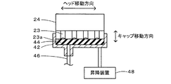
キャッピング装置40は、図3に示すように、上方が開口した略直方体のキャップ42と、例えばゴムなどによって形成されてキャップ42の内部に配置されて印刷ヘッド24の複数のノズル23が形成された面(以下、ノズル形成面23aという)に当接可能な当接部材44と、キャップ42の底部と廃液タンク45とを接続する排出路46と、当接部材44とノズル形成面23aとの当接やその解除を行なうためにキャップ42を昇降させる昇降装置48と、を備える。このキャッピング装置40は、印刷ヘッド24がキャリッジ22と共にキャッピング装置40上の位置(いわゆるホームポジション)に移動したときに、当接部材44がノズル形成面23aに当接するよう昇降装置48によってキャップ42を上昇させることにより、全てのノズル23を封止できる(複数のノズル23をそれぞれ独立して封止できる)ようになっている。キャッピング装置40によって複数のノズル23を封止する様子を図4に示す。また、このキャッピング装置40では、ノズル形成面23aと当接部材44とが若干(数mmなど)離れてノズル形成面23aとキャップ42とによって閉空間が形成されている状態で複数のノズル23からインクが吐出された場合には、そのインクがキャップ42と当接部材44との隙間や排出路46を経由して廃液タンク45に排出される。
As shown in FIG. 3, the
コントローラー90は、図1に示すように、CPU92を中心とするマイクロプロセッサーとして構成されており、各種処理プログラムを記憶したROM93と、一時的にデータを記憶するRAM94と、外部機器との情報のやり取りを行うインターフェース(I/F)95と、図示しない入出力ポートとを備える。RAM94には、印刷バッファー領域が設けられており、この印刷バッファー領域にユーザーPC100からI/F95を介して送られてきた印刷データが記憶される。コントローラー90には、リニア式エンコーダー25からの位置検出信号や、サブタンク53のインクの液面の位置(高さ)が所定位置Href以上の場合にオンすると共にサブタンク53のインクの液面の位置(高さ)が所定位置Hrefより低い場合にオフするフロートスイッチ59(図2参照)からのスイッチ信号,操作パネル97の操作部99からの操作信号などが入力ポートを介して入力される他、ユーザーPC100からの印刷ジョブなどがI/F95を介して入力される。ここで、所定位置Hrefは、本実施形態では、サブタンク53のインクの液面とノズル形成面23aとの高低差(水頭差)ΔHが所定値ΔH1となる位置、即ち、ノズル形成面23aより所定値ΔH1だけ低い位置とするものとした。所定値ΔH1は、サブタンク53が大気開放されている場合に、ノズル23内のインクに作用する圧力が、ノズル形成面23a側からノズル23に空気が侵入するのを抑止することができると共にノズル23からインクが漏れ出るのを抑止可能な圧力として定められた所定負圧(例えば、−1kPaや−0.8kPaなど)となるよう定められており、例えば、90mmや100mm,110mmなどとすることができる。コントローラー90からは、印刷ヘッド24への制御信号や、駆動モーター33やキャリッジモーター34への制御信号,キャッピング装置40の昇降装置48(図3参照)への制御信号,供給ポンプ58や循環ポンプ76,開閉弁78,圧力調整装置80(図2参照)への制御信号,操作パネル97の表示部98への表示制御信号などが出力ポートを介して出力される他、印刷ステータス情報などがI/F95を介してユーザーPC100に出力される。
As shown in FIG. 1, the
こうして構成された本実施形態のインクジェットプリンター20では、印刷ヘッド24の複数のノズル23からインク滴を吐出して用紙Pに印刷処理を行なう場合には、開閉弁78が開成された状態で供給ポンプ58および循環ポンプ76が共に正転方向に回転するよう供給ポンプ58と循環ポンプ76と開閉弁78とを制御することにより、メインタンク52のインクをサブタンク53に供給し、サブタンク53のインクを往路口69側から印刷ヘッド24に供給すると共にその一部を印刷ヘッド24を経由して復路口73側からサブタンク53に戻している。本実施形態では、上述したように、循環路60の往路口69が循環路60の復路口73や供給路54の供給口56より低い位置になるようにすることにより、印刷処理を行なうときに、空気(気泡)が往路口69から循環路60に侵入して印刷ヘッド24に到達するのを抑制している。これにより、印刷処理をより適正に行なうことができる。なお、サブタンク53内に発生する気泡としては、供給路54を経由してメインタンク52からサブタンク53に圧送されたインクに含まれる気泡や、循環路60の復路口73からサブタンク53に放出されるインクに含まれる気泡などがある。
In the
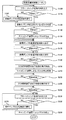
次に、こうして構成された本実施形態のインクジェットプリンター20の動作、特に、印刷ヘッド24(複数のノズル23を含む)にインクを充填する初期充填時の動作について説明する。図5は、コントローラー90により実行される初期充填時制御ルーチンの一例を示すフローチャートである。このルーチンは、印刷ヘッド24へのインクの充填が指示されたときに実行される。なお、このルーチンの実行開始時には、本実施形態では、圧力調整装置80によってサブタンク53は大気開放されており、開閉弁78は開成されているものとした。
Next, the operation of the
初期充填時制御ルーチンが実行されると、コントローラー90は、まず、フロートスイッチ59からのフロートスイッチ信号FSWを入力すると共に(ステップS100)、入力したフロートスイッチ信号FSWを調べ(ステップS110)、フロートスイッチ信号FSWがオフの場合、即ち、サブタンク53のインクの液面の位置(高さ)がノズル形成面23aより所定値ΔH1だけ低い所定位置Hrefより低い場合には、循環ポンプ76が正転方向に回転するよう(メインタンク52側からサブタンク53側にインクが圧送されるよう)供給ポンプ58を制御して(ステップS120)、ステップS100に戻る。このステップS100〜S120の処理は、ノズル23内のインクに作用する圧力(負圧)を調整する処理である。
When the initial filling control routine is executed, the
ステップS110でフロートスイッチ信号FSWがオンの場合、即ち、サブタンク53のインクの液面の位置(高さ)が所定位置Href以上の場合には、キャッピング装置40によって複数のノズル23が封止されているか否かを判定し(ステップS130,S140)、複数のノズル23が封止されていないと判定された場合には、キャッピング装置40の当接部材44がノズル形成面23aに当接して複数のノズル23が封止されるようキャッピング装置40を制御する(ステップS150)。ここで、ステップS130,S140の判定は、キャップ42の位置を調べることによって行なったり、ノズル形成面23aと当接部材44とが当接しているか否かを調べることによって行なったりすることができる。なお、ステップS130,S140で複数のノズル23が封止されていると判定された場合には、ステップS150の処理を実行せずに次の処理に進む。
If the float switch signal FSW is ON in step S110, that is, if the position (height) of the ink level in the
続いて、比較的高い回転数として定められた所定回転数N1で循環ポンプ76が正転方向に回転するよう循環ポンプ76を制御する高速正転制御を所定時間t1に亘って実行する(ステップS160,S170)。ここで、所定時間t1は、印刷ヘッド24を含む循環路60のインクの充填や循環路60内の空気(気泡)のサブタンク53への放出などに要する時間として定められ、本実施形態では、高速正転制御を実行したときに循環路60全体の体積のn倍(nは予め定められた2以上の整数)のインクが循環路60を循環するのに要する時間とした。この所定時間t1は、例えば、2分や3分,4分などとすることができる。このようにキャッピング装置40によって複数のノズル23を封止した状態で循環ポンプ76によってインクを循環路60を循環させることにより、複数のノズル23からインクが放出される(漏れ出る)のを抑止しながら印刷ヘッド24にインクを充填することができる。しかも、この場合、比較的大きな流量でインクを循環路60を循環させることができる。さらに、循環路60全体の体積のn倍のインクを循環路60を循環させるから、循環路60全体の体積分のインクを循環路60を循環させるものに比して循環路60の気泡をより確実にサブタンク53に放出させることができる。加えて、上述したように、循環路60の往路口69が循環路60の復路口73より低い位置となるようにしているから、空気(気泡)が往路口69から循環路60に流入して印刷ヘッド24に到達するのを抑制することができる。なお、キャッピング装置40によって複数のノズル23を封止しているため、複数のノズル23の形状などによっては、複数のノズル23内の空気(気泡)が復路口73側に移動せずにそのまま残留する可能性がある。
Subsequently, high-speed forward rotation control for controlling the
こうして高速正転制御を実行すると、続いて、所定回転数N1より低い回転数として定められた所定回転数N2で循環ポンプ76が正転方向に回転するよう循環ポンプ76を制御する低速正転制御を所定時間t2に亘って実行する(ステップS180,S190)。ここで、所定時間t2は、循環路60のインクの流れの安定などに要する時間として定められ、例えば、25秒や30秒,35秒などとすることができる。
When the high-speed forward rotation control is executed in this way, subsequently, the low-speed forward rotation control for controlling the
次に、圧力調整装置80によってサブタンク53が加圧されるよう圧力調整装置80を制御する加圧制御の実行を開始し(ステップS200)、キャッピング装置40による複数のノズル23の封止が解除されるようキャッピング装置40を制御し(ステップS210)、その状態で所定時間t3が経過するのを待つ(ステップS220)。ここで、加圧制御は、ノズル23内のインクに作用する圧力が正圧(例えば、10kPaや12kPaなど)となるようサブタンク53を加圧する制御である。また、複数のノズル23の封止の解除は、ノズル形成面23aと当接部材44とが若干(数mmなど)離れてノズル形成面23aとキャップ42とによって閉空間が形成される状態とするものとした。このように加圧制御を実行しながら複数のノズル23の封止を解除すると、サブタンク53のインクが印刷ヘッド24側に流れ、複数のノズル23からインクと共に空気(気泡)が放出される。なお、複数のノズル23から放出されたインクは、キャップ42と当接部材44との隙間や排出路46を経由して廃液タンク45に排出される。こうしたステップS200〜S220の処理により、複数のノズル23内の空気を十分に放出させることができる。所定時間t3は、複数のノズル23からの空気の放出に要する時間として定められ、例えば、3秒や5秒,7秒などとすることができる。しかも、本実施形態では、高速正転制御や低速正転制御を実行した後にキャッピング装置40による複数のノズル23の封止を解除するから、複数のノズル23を封止せずに高速正転制御や低速正転制御を実行する場合に比してノズル23からのインクの放出量を抑制することができる。
Next, execution of pressurization control for controlling the
こうして所定時間t3が経過すると、加圧制御の実行を終了してサブタンク53を大気開放された状態として(ステップS230)、所定時間t4が経過するのを待つ(ステップS240)。ここで、所定時間t4は、複数のノズル23内のインクのメニスカスが安定するまでに要する時間として定められ、例えば、8秒や10秒,12秒などとすることができる。
When the predetermined time t3 elapses, the execution of the pressurization control is terminated and the
そして、フロートスイッチ59からのフロートスイッチ信号FSWを入力すると共に(ステップ250)、入力したフロートスイッチ信号FSWを調べ(ステップS260)、フロートスイッチ信号FSWがオフの場合には、循環ポンプ76が正転方向に回転するよう(メインタンク52側からサブタンク53側にインクが圧送されるよう)供給ポンプ58を制御して(ステップS270)、ステップS250に戻る。一方、ステップS260でフロートスイッチ信号FSWがオンの場合には、キャッピング装置40によって複数のノズル23が封止されるようキャッピング装置40を制御して(ステップS280)、本ルーチンを終了する。
Then, the float switch signal FSW from the
ここで、本実施形態の構成要素と本発明の構成要素との対応関係を明らかにする。本実施形態の印刷ヘッド24が「吐出ヘッド」に相当し、サブタンク53が「貯留部」に相当し、循環路60が「循環路」に相当し、循環ポンプ76が「圧送手段」に相当し、キャッピング装置40が「封止手段」に相当し、圧力調整装置80が「加圧手段」に相当し、図5の初期充填時制御ルーチンを実行するコントローラー90が「充填時制御手段」に相当する。なお、本実施形態では、液体吐出装置の動作を説明することにより本発明の液体吐出装置の制御方法の一例も明らかにしている。
Here, the correspondence between the components of the present embodiment and the components of the present invention will be clarified. The
以上説明した本実施形態のインクジェットプリンター20によれば、印刷ヘッド24にインクを充填する際には、キャッピング装置40によって複数のノズル23がそれぞれ独立して封止された状態で循環ポンプ76の駆動によってインクが循環路60を循環するようキャッピング装置40と循環ポンプ76とを制御し、その後に、圧力調整装置80によってサブタンク53が加圧されながらキャッピング装置40による複数のノズル23の封止が解除されるよう圧力調整装置80とキャッピング装置40とを制御するから、複数のノズル23からインクが放出されるのを抑止しながら印刷ヘッド24にインクを充填することができると共にその後に複数のノズル23から空気(気泡)を放出させることができる。即ち、複数のノズル23を含む印刷ヘッド24にインクを充填する際のインクの無駄を抑制することができると共に循環路60(複数のノズル23を含む)内の空気を十分に除去することができる。
According to the
なお、本発明は上述した実施形態に何ら限定されることはなく、本発明の技術的範囲に属する限り種々の態様で実施し得ることはいうまでもない。 It should be noted that the present invention is not limited to the above-described embodiment, and it goes without saying that the present invention can be implemented in various modes as long as it belongs to the technical scope of the present invention.
上述した実施形態では、印刷ヘッド24にインクを充填する初期充填時の動作について説明したが、印刷ヘッド24のクリーニングを行なう場合にも同様の動作を行なうものとしてもよい。この場合、例えば、所定時間t1については50秒や1分,1分10秒などとし、所定時間t2については25秒や30秒,35秒などとし、所定時間t3については3秒や5秒,7秒などとし、所定時間t4については8秒や10秒,12秒などとするものとしてもよい。なお、印刷ヘッド24のクリーニングを実行するタイミングとしては、メインタンク52やサブタンク53が交換されたときや、操作部99の操作によってクリーニングが指示されたときなどが考えられる。
In the above-described embodiment, the operation at the time of initial filling in which the
上述した実施形態では、高速正転制御を実行したときに循環路60全体の体積のn倍(nは予め定められた2以上の整数)以上のインクが循環路60を循環するのに要する時間としての所定時間t1に亘って高速正転制御を実行するものとしたが、所定時間t1より短い所定時間t11の高速正転制御を実行するものとしてもよいし、所定時間t1や所定時間t11の高速正転制御をm回(mは予め定められた2以上の整数)実行するものとしてもよい。ここで、所定時間t11は、高速正転制御を実行したときに循環路60全体の体積のインクが循環路60を循環するのに要する時間やそれよりも若干長い時間などとすることができる。
In the above-described embodiment, when high-speed forward rotation control is executed, the time required for the ink of n times or more (n is a predetermined integer of 2 or more) of the
上述した実施形態では、高速正転制御を所定時間t1に亘って実行すると共に低速正転制御を所定時間t2に亘って実行し、その後に、圧力調整装置80によってサブタンク53を加圧しながらキャッピング装置40による複数のノズル23の封止を解除するものとしたが、高速正転制御を所定時間t1に亘って実行した後に低速正転制御を実行せずにサブタンク53を加圧しながらキャッピング装置40による複数のノズル23の封止を解除するものとしてもよい。
In the above-described embodiment, the high speed forward rotation control is performed over the predetermined time t1 and the low speed forward rotation control is performed over the predetermined time t2, and then the capping device while pressurizing the
上述した実施形態では、加圧制御の実行を終了した後に所定時間t4が経過するのを待って必要に応じて供給ポンプ58を制御するものとしたが、加圧制御の実行を終了した後に所定時間t4が経過するのを待たずに必要に応じて供給ポンプ58を制御するものとしてもよい。
In the above-described embodiment, the
上述した実施形態では、加圧制御の実行を終了した後に必要に応じてメインタンク52からサブタンク53にインクを圧送するものとしたが、加圧制御の実行を終了した後にはメインタンク52からサブタンク53にインクを圧送しないものとしてもよい。
In the above-described embodiment, the ink is pressure-fed from the
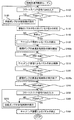
上述した実施形態では、高速正転制御や低速正転制御の実行後に圧力調整装置80によってサブタンク53を加圧しながらキャッピング装置40による複数のノズル23の封止を解除するものとしたが、供給ポンプ58を正転方向に回転させながらキャッピング装置40による複数のノズル23の封止を解除するものとしてもよいし、圧力調整装置80によってサブタンク53を加圧すると共に供給ポンプ58を正転方向に回転させながらキャッピング装置40による複数のノズル23の封止を解除するものとしてもよい。前者の場合の初期充填時制御ルーチンの一例を図6に示す。このルーチンは、図5の初期充填時制御ルーチンのステップS180〜S200の処理を実行せず、ステップS160,S230の処理に代えてステップS160b,S230bの処理を実行する点を除いて、図5の初期充填時制御ルーチンと同一である。したがって、同一の処理については同一のステップ番号を付し、その詳細な説明は省略する。この初期充填時制御ルーチンでは、サブタンク53のインクの液面の位置(高さ)がノズル形成面23aより所定値ΔH1だけ低い所定位置Href以上で且つキャッピング装置40によって複数のノズル23が封止されている状態で(ステップS100〜S150)、所定回転数N1で循環ポンプ76が正転方向に回転するよう循環ポンプ76を制御する高速正転制御の実行を開始し(ステップS160b)、所定時間t1が経過するのを待って(ステップS170)、キャッピング装置40による複数のノズル23の封止が解除されるようキャッピング装置40を制御し(ステップS210)、その状態で所定時間t3が経過するのを待って(ステップS220)、高速正転制御の実行を終了し(ステップS230b)、ステップS240以降の処理を実行する。この場合、インクを循環路60を循環させながらキャッピング装置40による複数のノズル23の封止を解除することにより、複数のノズル23からインクと共に空気(気泡)を放出させることができる。したがって、上述した実施形態と同様に、複数のノズル23からインクが放出されるのを抑止しながら印刷ヘッド24にインクを充填することができると共にその後に複数のノズル23内から空気を放出させることができる。即ち、複数のノズル23を含む印刷ヘッド24にインクを充填する際のインクの無駄を抑制することができると共に循環路60(複数のノズル23を含む)内の空気を十分に除去することができる。なお、この場合、圧力調整装置80を備えず、サブタンク53は大気開放されているものとしてもよい。また、図6の初期充填時制御ルーチンでは、供給ポンプ58を正転方向に回転させながらキャッピング装置40による複数のノズル23の封止を解除する場合について説明したが、圧力調整装置80によってサブタンク53を加圧すると共に供給ポンプ58を正転方向に回転させながらキャッピング装置40による複数のノズル23の封止を解除するものとすれば、複数のノズル23内の空気をより確実に除去することができると考えられる。この変形例では、キャッピング装置40によって複数のノズル23を封止した状態でインクを循環路60を循環させる際の循環ポンプ76の回転数とキャッピング装置40による複数のノズル23の封止を解除する際の循環ポンプ76の回転数とを同一の所定回転数N1とするものとしたが、複数のノズル23の封止を解除する際の循環ポンプ76の回転数を所定回転数N1より高い回転数としてもよい。こうすれば、複数のノズル23内の空気をノズル23からより確実に除去することができる。また、この変形例では、高速正転制御の実行を開始してから所定時間t1が経過するのを待ってキャッピング装置40による複数のノズル23の封止を解除するものとしたが、高速正転制御の実行を開始してから上述の所定時間t11が経過するのを待ってキャッピング装置40による複数のノズル23の封止を解除するものとしてもよいし、所定時間t1や所定時間t11の高速正転制御をm回(mは予め定められた2以上の整数)実行した後に高速正転制御を実行しながらキャッピング装置40による複数のノズル23の封止を解除するものとしてもよい。さらに、この変形例では、高速正転制御の実行を終了した後に所定時間t4が経過するのを待って必要に応じて供給ポンプ58を制御するものとしたが、高速正転制御の実行を終了した後に所定時間t4が経過するのを待たずに必要に応じて供給ポンプ58を制御するものとしてもよいし、高速正転制御の実行を終了した後には供給ポンプ58を制御しないものとしてもよい。
In the embodiment described above, the sealing of the plurality of
上述した実施形態では、循環路60の往路口69が復路口73より低くなるようにするものとしたが、往路口69と復路口73との高さが略等しくなるようにするものとしてもよい。
In the embodiment described above, the
上述した実施形態では、供給ポンプ58は、ギヤポンプを用いるものとしたが、チューブポンプなどを用いるものとしてもよい。循環ポンプ76についても同様に、チューブポンプなどを用いるものとしてもよい。
In the embodiment described above, the
上述した実施形態では、インク循環システム50は、メインタンク52とサブタンク53と供給路54と供給ポンプ58と循環路60と循環ポンプ76と開閉弁78と圧力調整装置80とを備えるものとしたが、メインタンク52や供給路54,供給ポンプ58を備えないものとしてもよい。
In the embodiment described above, the
上述した実施形態では、一つの印刷ヘッド24を備えるインクジェットプリンター20について説明したが、複数の印刷ヘッドを備えるインクジェットプリンターに適用するものとしてもよい。
In the embodiment described above, the
上述した実施形態では、本発明の液体吐出装置をインクジェットプリンター20に具体化した例を示したが、インク以外の他の液体や機能材料の粒子が分散されている液状体(分散液)、ジェルのような流状体などを吐出する流体吐出装置に具体化してもよい。例えば、液晶ディスプレイ、EL(エレクトロルミネッセンス)ディスプレイ及び面発光ディスプレイの製造などに用いられる電極材や色材などの材料を溶解した液体を吐出する液体吐出装置、同材料を分散した液状体を吐出する液状体吐出装置、精密ピペットとして用いられ試料となる液体を吐出する液体吐出装置としてもよい。また、時計やカメラ等の精密機械にピンポイントで潤滑油を吐出する液体吐出装置、光通信素子等に用いられる微小半球レンズ(光学レンズ)などを形成するために紫外線硬化樹脂等の透明樹脂液を基板上に吐出する液体吐出装置、基板などをエッチングするために酸又はアルカリ等のエッチング液を吐出する液体吐出装置、ジェルを吐出する流状体吐出装置としてもよい。
In the embodiment described above, an example in which the liquid ejecting apparatus of the present invention is embodied in the
上述した実施形態では、本発明の液体吐出装置をインクジェットプリンター20に適用して説明したが、これに限定されるものではなく、液体を吐出するノズルを有する吐出ヘッドを備える液体吐出装置の形態であればよく、例えば、ファクシミリ装置や複合機などの他の如何なるOA機器に適用するものとしてもよい。
In the above-described embodiment, the liquid ejection apparatus of the present invention is applied to the
20 インクジェットプリンター、21 プリンター機構、22 キャリッジ、23 ノズル、23a ノズル形成面、24 印刷ヘッド、25 リニア式エンコーダー、28 ガイド、32 キャリッジベルト、33 駆動モーター、34 キャリッジモーター、35 紙送りローラー、36 プラテン、40 キャッピング装置、42 キャップ、44 当接部材、45 廃液タンク、46 排出路、48 昇降装置、50,50a〜50d インク循環システム、52 メインタンク、53 サブタンク、54 供給路、55 供給源口、56 供給口、57 インク検出センサー、58 供給ポンプ、60 循環路、62 往路、64 復路、69 往路口、73 復路口、76 循環ポンプ、78 開閉弁、80 圧力調整装置、90 コントローラー、92 CPU,93 ROM、94 RAM、95 インターフェース(I/F)、97 操作パネル、98 表示部、99 操作部、100 ユーザーPC。 20 Inkjet printer, 21 Printer mechanism, 22 Carriage, 23 Nozzle, 23a Nozzle forming surface, 24 Print head, 25 Linear encoder, 28 Guide, 32 Carriage belt, 33 Drive motor, 34 Carriage motor, 35 Paper feed roller, 36 Platen , 40 Capping device, 42 Cap, 44 Contact member, 45 Waste liquid tank, 46 Discharge path, 48 Lifting device, 50, 50a to 50d Ink circulation system, 52 main tank, 53 sub tank, 54 supply path, 55 supply source port, 56 Supply port, 57 Ink detection sensor, 58 Supply pump, 60 Circulation path, 62 Outward path, 64 Return path, 69 Outbound port, 73 Return path port, 76 Circulation pump, 78 On-off valve, 80 Pressure adjusting device, 90 Controller, 9 CPU, 93 ROM, 94 RAM, 95 interface (I / F), 97 operation panel, 98 display unit, 99 operation unit, 100 user PC.
Claims (8)
液体を貯留する貯留部と、
前記吐出ヘッドを含んで構成され、一方の開口端部と他方の開口端部とが共に前記貯留部内に配置された循環路と、
前記循環路における前記吐出ヘッドより前記一方の開口端部側に設けられ、液体が前記循環路を循環するよう液体を圧送可能な圧送手段と、
前記複数のノズルをそれぞれ独立して封止可能な封止手段と、
前記貯留部を加圧可能な加圧手段と、
前記吐出ヘッドに液体を充填する際、前記封止手段によって前記複数のノズルがそれぞれ独立して封止された状態で前記圧送手段の駆動によって液体が前記循環路を循環するよう前記封止手段と前記圧送手段とを制御する第1制御を実行し、該第1制御の実行後に、前記加圧手段によって前記貯留部が加圧されながら前記封止手段による前記複数のノズルの封止が解除されるよう前記加圧手段と前記封止手段とを制御する第2制御を実行する充填時制御手段と、
を備える液体吐出装置。 A liquid discharge apparatus comprising a discharge head having a plurality of nozzles for discharging liquid,
A reservoir for storing liquid;
A circulation path configured to include the discharge head, wherein one opening end and the other opening end are both disposed in the storage unit;
A pressure-feeding means that is provided closer to the one opening end than the discharge head in the circulation path and capable of pumping the liquid so that the liquid circulates in the circulation path;
Sealing means capable of independently sealing the plurality of nozzles;
Pressurizing means capable of pressurizing the reservoir,
When the discharge head is filled with liquid, the sealing means is configured so that the liquid circulates through the circulation path by driving the pressure feeding means in a state where the plurality of nozzles are independently sealed by the sealing means. The first control for controlling the pressure feeding unit is performed, and after the first control is performed, the sealing of the plurality of nozzles by the sealing unit is released while the reservoir is pressurized by the pressure unit. Filling control means for executing a second control for controlling the pressurizing means and the sealing means;
A liquid ejection apparatus comprising:
前記充填時制御手段は、前記第2制御として、前記加圧手段によって前記貯留部が加圧されると共に前記圧送手段の駆動によって液体が前記循環路を循環しながら前記封止手段による前記複数のノズルの封止が解除されるよう前記圧送手段と前記加圧手段と前記封止手段とを制御する手段である、
液体吐出装置。 The liquid ejection device according to claim 1,
The filling time control means, as the second control, pressurizes the reservoir by the pressurizing means and drives the pumping means to circulate the liquid through the circulation path while the plurality of sealing means by the sealing means. A means for controlling the pressure feeding means, the pressure means and the sealing means so as to release the sealing of the nozzle;
Liquid ejection device.
液体を貯留する貯留部と、
前記吐出ヘッドを含んで構成され、一方の開口端部と他方の開口端部とが共に前記貯留部内に配置された循環路と、
前記循環路における前記吐出ヘッドより前記一方の開口端部側に設けられ、液体が前記循環路を循環するよう液体を圧送可能な圧送手段と、
前記複数のノズルをそれぞれ独立して封止可能な封止手段と、
前記吐出ヘッドに液体を充填する際、前記封止手段によって前記複数のノズルがそれぞれ独立して封止された状態で前記圧送手段の駆動によって液体が前記循環路を循環するよう前記封止手段と前記圧送手段とを制御する第1制御を実行し、該第1制御の実行後に、前記圧送手段の駆動によって液体が前記循環路を循環しながら前記封止手段による前記複数のノズルの封止が解除されるよう前記圧送手段と前記封止手段とを制御する第2制御を実行する充填時制御手段と、
を備える液体吐出装置。 A liquid discharge apparatus comprising a discharge head having a plurality of nozzles for discharging liquid,
A reservoir for storing liquid;
A circulation path configured to include the discharge head, wherein one opening end and the other opening end are both disposed in the storage unit;
A pressure-feeding means that is provided closer to the one opening end than the discharge head in the circulation path and capable of pumping the liquid so that the liquid circulates in the circulation path;
Sealing means capable of independently sealing the plurality of nozzles;
When the discharge head is filled with liquid, the sealing means is configured so that the liquid circulates through the circulation path by driving the pressure feeding means in a state where the plurality of nozzles are independently sealed by the sealing means. The first control for controlling the pressure feeding unit is performed, and after the first control is performed, the sealing unit seals the plurality of nozzles while the liquid circulates through the circulation path by driving the pressure feeding unit. A filling time control means for executing a second control for controlling the pressure feeding means and the sealing means to be released; and
A liquid ejection apparatus comprising:
前記充填時制御手段は、前記第1制御として、前記循環路全体の体積の複数倍以上の液体が前記循環路を循環するよう前記圧送手段を制御する手段である、
液体吐出装置。 The liquid ejection device according to any one of claims 1 to 3,
The filling-time control means is means for controlling the pumping means so that a liquid having a multiple of the volume of the entire circulation path circulates in the circulation path as the first control.
Liquid ejection device.
前記充填時制御手段は、前記第1制御として、複数回に亘って液体が前記循環路を循環するよう前記圧送手段を制御する手段である、
液体吐出装置。 A liquid ejection apparatus according to any one of claims 1 to 4, wherein
The filling time control means is means for controlling the pressure feeding means so that the liquid circulates through the circulation path a plurality of times as the first control.
Liquid ejection device.
前記一方の開口端部は、前記他方の開口端部より低い位置に配置されてなり、
前記充填時制御手段は、液体が前記循環路を循環するよう前記圧送手段を制御する際、液体が前記一方の開口端部側から前記吐出ヘッドを経由して前記他方の開口端部側に循環するよう前記圧送手段を制御する手段である、
液体吐出装置。 The liquid ejection device according to any one of claims 1 to 5,
The one opening end is arranged at a position lower than the other opening end,
The filling-time control means circulates the liquid from the one opening end side to the other opening end side via the discharge head when controlling the pumping means so that the liquid circulates in the circulation path. Means for controlling the pumping means to
Liquid ejection device.
前記吐出ヘッドに液体を充填する際、前記封止手段によって前記複数のノズルがそれぞれ独立して封止された状態で前記圧送手段の駆動によって液体が前記循環路を循環するよう前記封止手段と前記圧送手段とを制御する第1制御を実行し、該第1制御の実行後に、前記加圧手段によって前記貯留部が加圧されながら前記封止手段による前記複数のノズルの封止が解除されるよう前記加圧手段と前記封止手段とを制御する第2制御を実行する、
液体吐出装置の制御方法。 A discharge head having a plurality of nozzles for discharging liquid, a storage portion for storing liquid, and one opening end portion and the other opening end portion including the discharge head are arranged in the storage portion. The circulation path, the pressure feeding means provided on the one opening end side from the discharge head in the circulation path and capable of pumping the liquid so that the liquid circulates in the circulation path, and the plurality of nozzles are sealed independently. A control method of a liquid ejection device comprising: a sealing unit that can be stopped; and a pressurizing unit that can pressurize the storage unit,
When the discharge head is filled with liquid, the sealing means is configured so that the liquid circulates through the circulation path by driving the pressure feeding means in a state where the plurality of nozzles are independently sealed by the sealing means. The first control for controlling the pressure feeding unit is performed, and after the first control is performed, the sealing of the plurality of nozzles by the sealing unit is released while the reservoir is pressurized by the pressure unit. Executing a second control for controlling the pressurizing means and the sealing means,
Control method of liquid ejection apparatus.
前記吐出ヘッドに液体を充填する際、前記封止手段によって前記複数のノズルがそれぞれ独立して封止された状態で前記圧送手段の駆動によって液体が前記循環路を循環するよう前記封止手段と前記圧送手段とを制御する第1制御を実行し、該第1制御の実行後に、前記圧送手段の駆動によって液体が前記循環路を循環しながら前記封止手段による前記複数のノズルの封止が解除されるよう前記圧送手段と前記封止手段とを制御する第2制御を実行する、
液体吐出装置の制御方法。 A discharge head having a plurality of nozzles for discharging liquid, a storage portion for storing liquid, and one opening end portion and the other opening end portion including the discharge head are arranged in the storage portion. The circulation path, the pressure feeding means provided on the one opening end side from the discharge head in the circulation path and capable of pumping the liquid so that the liquid circulates in the circulation path, and the plurality of nozzles are sealed independently. A control method of a liquid ejection device comprising:
When the discharge head is filled with liquid, the sealing means is configured so that the liquid circulates through the circulation path by driving the pressure feeding means in a state where the plurality of nozzles are independently sealed by the sealing means. The first control for controlling the pressure feeding unit is performed, and after the first control is performed, the sealing unit seals the plurality of nozzles while the liquid circulates through the circulation path by driving the pressure feeding unit. Executing a second control for controlling the pressure feeding means and the sealing means to be released;
Control method of liquid ejection apparatus.
Priority Applications (5)
| Application Number | Priority Date | Filing Date | Title |
|---|---|---|---|
| JP2011047523A JP5776226B2 (en) | 2011-03-04 | 2011-03-04 | Liquid ejecting apparatus and control method thereof |
| CN201210039190.9A CN102653170B (en) | 2011-03-04 | 2012-02-20 | Liquid discharging apparatus and control method thereof |
| US13/410,064 US8690301B2 (en) | 2011-03-04 | 2012-03-01 | Liquid discharging apparatus and control method thereof |
| EP12157885.0A EP2495102B1 (en) | 2011-03-04 | 2012-03-02 | Liquid discharging apparatus and control method thereof |
| US14/184,468 US8939562B2 (en) | 2011-03-04 | 2014-02-19 | Liquid discharging apparatus and control method thereof |
Applications Claiming Priority (1)
| Application Number | Priority Date | Filing Date | Title |
|---|---|---|---|
| JP2011047523A JP5776226B2 (en) | 2011-03-04 | 2011-03-04 | Liquid ejecting apparatus and control method thereof |
Publications (2)
| Publication Number | Publication Date |
|---|---|
| JP2012183694A true JP2012183694A (en) | 2012-09-27 |
| JP5776226B2 JP5776226B2 (en) | 2015-09-09 |
Family
ID=45808246
Family Applications (1)
| Application Number | Title | Priority Date | Filing Date |
|---|---|---|---|
| JP2011047523A Active JP5776226B2 (en) | 2011-03-04 | 2011-03-04 | Liquid ejecting apparatus and control method thereof |
Country Status (4)
| Country | Link |
|---|---|
| US (2) | US8690301B2 (en) |
| EP (1) | EP2495102B1 (en) |
| JP (1) | JP5776226B2 (en) |
| CN (1) | CN102653170B (en) |
Cited By (1)
| Publication number | Priority date | Publication date | Assignee | Title |
|---|---|---|---|---|
| CN104290455A (en) * | 2013-07-18 | 2015-01-21 | 北大方正集团有限公司 | Ink feeding device and printing ink head surface meniscus forming method |
Families Citing this family (19)
| Publication number | Priority date | Publication date | Assignee | Title |
|---|---|---|---|---|
| JP6099941B2 (en) * | 2012-11-14 | 2017-03-22 | 株式会社ミマキエンジニアリング | Inkjet printing apparatus, nozzle clogging recovery method, and nozzle clogging recovery program |
| CN104786652A (en) * | 2014-01-22 | 2015-07-22 | 赵跃峰 | Full-cycle ink-jet printer |
| CN104369538A (en) * | 2014-02-09 | 2015-02-25 | 赵跃峰 | Jet-printing machine constant-pressure direct-flow natural exhaust anti-ink-blocking method |
| US10124617B2 (en) * | 2014-06-16 | 2018-11-13 | Ricoh Company, Ltd. | Liquid stirrer and image forming apparatus including same |
| US9849679B2 (en) * | 2015-11-24 | 2017-12-26 | Brother Kogyo Kabushiki Kaisha | Liquid jetting apparatus, power transmission apparatus, and recording apparatus |
| JP6769037B2 (en) | 2016-01-29 | 2020-10-14 | ブラザー工業株式会社 | Inkjet recording device |
| JP6769038B2 (en) | 2016-01-29 | 2020-10-14 | ブラザー工業株式会社 | Inkjet recording device |
| JP2017154298A (en) * | 2016-02-29 | 2017-09-07 | 東芝テック株式会社 | Liquid circulation device and liquid discharge device |
| US11134925B2 (en) | 2016-03-01 | 2021-10-05 | The Procter & Gamble Company | Diaper adapted for collection of urine sample from an infant |
| WO2017151710A1 (en) | 2016-03-01 | 2017-09-08 | The Procter & Gamble Company | Diaper adapted for collection of uncontaminated and intact stool sample from an infant |
| CN107813606B (en) * | 2016-09-13 | 2020-04-28 | 东芝泰格有限公司 | Liquid circulation device, liquid discharge device, and liquid discharge method |
| JP6888333B2 (en) * | 2017-03-03 | 2021-06-16 | セイコーエプソン株式会社 | Liquid injection device |
| US11135104B2 (en) | 2017-06-27 | 2021-10-05 | The Procter & Gamble Company | Diaper product adapted for collection of exudate sample from an infant |
| EP3644923A1 (en) | 2017-06-27 | 2020-05-06 | The Procter and Gamble Company | Configurable absorbent articles having improved bodily exudate separation and sampling |
| CN109263285A (en) * | 2018-09-28 | 2019-01-25 | 岳阳宝丽纺织品有限公司 | A kind of nozzle sealing unit and spray head |
| CN109435476A (en) * | 2018-09-28 | 2019-03-08 | 岳阳宝丽纺织品有限公司 | A kind of injector seals method |
| JP7283129B2 (en) * | 2019-02-28 | 2023-05-30 | セイコーエプソン株式会社 | Supply device and liquid ejection device |
| JP7188410B2 (en) * | 2020-03-31 | 2022-12-13 | ブラザー工業株式会社 | Inkjet printer and circulation program |
| CN112721457B (en) * | 2020-12-23 | 2022-04-22 | 惠州市迪日科技发展有限公司 | Circulating ink supply system, ink-jet printing device and ink-jet printing equipment |
Citations (3)
| Publication number | Priority date | Publication date | Assignee | Title |
|---|---|---|---|---|
| JPH05330073A (en) * | 1992-06-03 | 1993-12-14 | Canon Inc | Method for restoring emission of recording head of ink jet recording apparatus |
| JPH07164640A (en) * | 1993-12-15 | 1995-06-27 | Ricoh Co Ltd | Ink jet recorder |
| JP2010105169A (en) * | 2008-10-28 | 2010-05-13 | Olympus Corp | Ink filling method |
Family Cites Families (23)
| Publication number | Priority date | Publication date | Assignee | Title |
|---|---|---|---|---|
| JP2916297B2 (en) | 1991-02-25 | 1999-07-05 | 三菱化学株式会社 | Phosphopeptide |
| JPH04337500A (en) | 1991-05-15 | 1992-11-25 | Toshiba Corp | Nuclear fuel assembly monitoring system |
| EP0714778B1 (en) | 1994-05-17 | 2000-03-22 | Seiko Epson Corporation | Ink jet recorder and method of cleaning recording head |
| JPH1029317A (en) | 1996-04-12 | 1998-02-03 | Xerox Corp | Method and unit for circulating ink in liquid ink printer |
| JPH10230623A (en) | 1997-02-21 | 1998-09-02 | Hitachi Koki Co Ltd | Method and apparatus for removing bubble from ink jet printer employing thermally fusible ink |
| JPH11198403A (en) | 1998-01-14 | 1999-07-27 | Canon Inc | Method and apparatus for forming image |
| JP3846083B2 (en) | 1998-02-06 | 2006-11-15 | ブラザー工業株式会社 | Inkjet recording device |
| JP3794165B2 (en) | 1998-06-01 | 2006-07-05 | ブラザー工業株式会社 | Inkjet printer |
| JP2004009475A (en) * | 2002-06-06 | 2004-01-15 | Hitachi Printing Solutions Ltd | Ink jet recording device and ink supply device used therein |
| JP4337500B2 (en) | 2003-10-24 | 2009-09-30 | ソニー株式会社 | Liquid ejection device |
| JP2005186352A (en) * | 2003-12-25 | 2005-07-14 | Seiko Epson Corp | Capping device, its control method, liquid droplet discharge device and device manufacturing method |
| JP2006247899A (en) | 2005-03-08 | 2006-09-21 | Fuji Xerox Co Ltd | Liquid droplet delivering apparatus |
| JP4642562B2 (en) * | 2005-06-28 | 2011-03-02 | 富士フイルム株式会社 | Ink tank manufacturing method and ink filling method |
| US7845784B2 (en) * | 2006-12-28 | 2010-12-07 | Kabushiki Kaisha Toshiba | Ink supplying mechanism and ink supplying method |
| JP2008260267A (en) * | 2007-03-16 | 2008-10-30 | Seiko Epson Corp | Pressure regulating mechanism and liquid discharging device |
| US7950764B2 (en) | 2007-03-16 | 2011-05-31 | Seiko Epson Corporation | Pressure regulating mechanism and liquid ejecting apparatus |
| JP4270300B2 (en) | 2007-03-30 | 2009-05-27 | ソニー株式会社 | Liquid ejection head, liquid ejection device, and bubble removal method for liquid ejection device |
| US20090002467A1 (en) * | 2007-06-28 | 2009-01-01 | Seiko Epson Corporation | Fluid ejecting apparatus and method for controlling the same |
| JP2009154328A (en) | 2007-12-25 | 2009-07-16 | Fuji Xerox Co Ltd | Liquid droplet discharge head and image forming apparatus equipped with the same |
| US20100103208A1 (en) | 2008-10-28 | 2010-04-29 | Olympus Corporation | Ink filling method and inkjet printer |
| JP5600910B2 (en) | 2009-08-31 | 2014-10-08 | セイコーエプソン株式会社 | Liquid ejecting apparatus and method for cleaning liquid ejecting head in liquid ejecting apparatus |
| US8414112B2 (en) * | 2009-09-03 | 2013-04-09 | Dell Products L.P. | High speed printing material delivery system |
| JP5779844B2 (en) | 2010-06-17 | 2015-09-16 | セイコーエプソン株式会社 | Liquid ejector |
-
2011
- 2011-03-04 JP JP2011047523A patent/JP5776226B2/en active Active
-
2012
- 2012-02-20 CN CN201210039190.9A patent/CN102653170B/en active Active
- 2012-03-01 US US13/410,064 patent/US8690301B2/en active Active
- 2012-03-02 EP EP12157885.0A patent/EP2495102B1/en active Active
-
2014
- 2014-02-19 US US14/184,468 patent/US8939562B2/en active Active
Patent Citations (3)
| Publication number | Priority date | Publication date | Assignee | Title |
|---|---|---|---|---|
| JPH05330073A (en) * | 1992-06-03 | 1993-12-14 | Canon Inc | Method for restoring emission of recording head of ink jet recording apparatus |
| JPH07164640A (en) * | 1993-12-15 | 1995-06-27 | Ricoh Co Ltd | Ink jet recorder |
| JP2010105169A (en) * | 2008-10-28 | 2010-05-13 | Olympus Corp | Ink filling method |
Cited By (1)
| Publication number | Priority date | Publication date | Assignee | Title |
|---|---|---|---|---|
| CN104290455A (en) * | 2013-07-18 | 2015-01-21 | 北大方正集团有限公司 | Ink feeding device and printing ink head surface meniscus forming method |
Also Published As
| Publication number | Publication date |
|---|---|
| EP2495102A1 (en) | 2012-09-05 |
| CN102653170B (en) | 2014-11-05 |
| US8690301B2 (en) | 2014-04-08 |
| CN102653170A (en) | 2012-09-05 |
| US8939562B2 (en) | 2015-01-27 |
| US20120223981A1 (en) | 2012-09-06 |
| EP2495102B1 (en) | 2018-11-28 |
| JP5776226B2 (en) | 2015-09-09 |
| US20140168296A1 (en) | 2014-06-19 |
Similar Documents
| Publication | Publication Date | Title |
|---|---|---|
| JP5776226B2 (en) | Liquid ejecting apparatus and control method thereof | |
| JP5776227B2 (en) | Liquid ejecting apparatus and control method thereof | |
| US6561637B2 (en) | Ink jet head having buffer tank in fluid communication with ink circulation pathway | |
| JP5884307B2 (en) | Liquid container, liquid container complex, and liquid supply system | |
| JP2006159811A (en) | Ink supply device and pressure generating method | |
| JP2006327123A (en) | Method of cleaning face surface and inkjet system image forming apparatus | |
| JP2009184132A (en) | Liquid delivering apparatus | |
| JP5732898B2 (en) | Liquid ejection device | |
| US8449053B2 (en) | Liquid ejecting apparatus and liquid charging method | |
| JP5272318B2 (en) | Fluid ejection apparatus and control method thereof | |
| JP2009051149A (en) | Liquid discharge device and method for controlling the same | |
| JP2010221460A (en) | Fluid jetting apparatus | |
| JP2016215477A (en) | Inkjet recording device, processing method before transportation for inkjet recording device | |
| JP2008149483A (en) | Method for cleaning recorder, and recorder | |
| JP2015089659A (en) | Discharge head recovery method, liquid droplet discharge device and image forming apparatus | |
| JP2007007944A (en) | Method and mechanism for filling ink | |
| JP2007276303A (en) | Flushing control method in inkjet recording device and inkjet recording device | |
| JP2006161648A (en) | Pump unit and recovering mechanism | |
| JP2006103056A (en) | Recording apparatus and ink feeding method | |
| JP2009202434A (en) | Fluid jetting apparatus | |
| JP2009126031A (en) | Ink discharge method for ink jet-system image forming apparatus | |
| JP2008238638A (en) | Liquid discharging device and leakage judgment method | |
| JP2007203713A (en) | Cap, maintenance unit of liquid jetting apparatus, and liquid jetting apparatus | |
| JP2006264205A (en) | Image forming device | |
| JP2008221549A (en) | Liquid ejector and liquid ejection method |
Legal Events
| Date | Code | Title | Description |
|---|---|---|---|
| A621 | Written request for application examination |
Free format text: JAPANESE INTERMEDIATE CODE: A621 Effective date: 20140227 |
|
| A977 | Report on retrieval |
Free format text: JAPANESE INTERMEDIATE CODE: A971007 Effective date: 20141030 |
|
| A131 | Notification of reasons for refusal |
Free format text: JAPANESE INTERMEDIATE CODE: A131 Effective date: 20141118 |
|
| A521 | Written amendment |
Free format text: JAPANESE INTERMEDIATE CODE: A523 Effective date: 20150115 |
|
| TRDD | Decision of grant or rejection written | ||
| A01 | Written decision to grant a patent or to grant a registration (utility model) |
Free format text: JAPANESE INTERMEDIATE CODE: A01 Effective date: 20150609 |
|
| A61 | First payment of annual fees (during grant procedure) |
Free format text: JAPANESE INTERMEDIATE CODE: A61 Effective date: 20150622 |
|
| R150 | Certificate of patent or registration of utility model |
Ref document number: 5776226 Country of ref document: JP Free format text: JAPANESE INTERMEDIATE CODE: R150 |
|
| S531 | Written request for registration of change of domicile |
Free format text: JAPANESE INTERMEDIATE CODE: R313531 |
|
| R350 | Written notification of registration of transfer |
Free format text: JAPANESE INTERMEDIATE CODE: R350 |